- Table of Contents
- Related Documents
-
| Title | Size | Download |
|---|---|---|
| 01-Hardware Information and Technical Specifications | 10.47 MB |
Contents
Service module naming conventions
Switch fabric module naming conventions
LSEM1YGS48CQSF0/LSEM3YGS48CQSF0
LSEM1TGS48QSSF0/LSEM3TGS48QSSF0
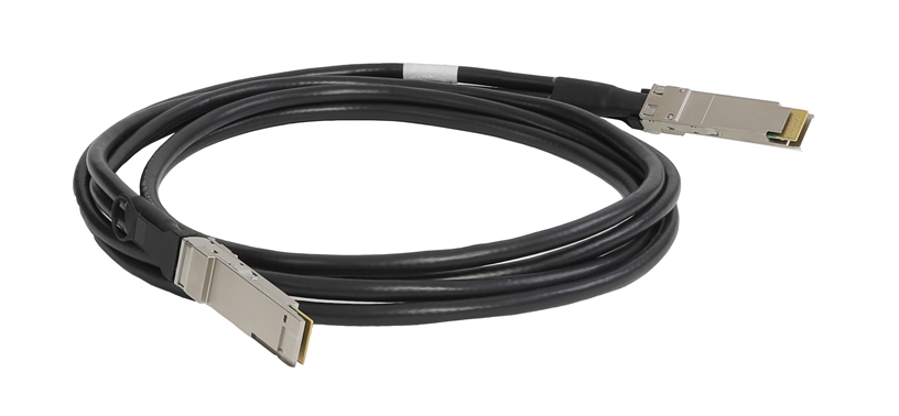
Making an Ethernet twisted pair cable
Chassis
H3C S10500X-G switch series is a set of core switching products designed for the cloud computing data centers. It uses the advanced multi-stage multi-plane CLOS architecture to deliver the industry's highest switching performance, port density, availability, and most abundant cloud computing features.
Chassis information
Chassis views
H3C S10500X-G switch series includes the S10506X-G, S10506X-G-PoE, S10508X-G, and S10512X-G models.
|
|
NOTE: · The chassis view figures are for illustration only. · The terms "MPU" and "supervisor engine unit" are used interchangeably in this document. · Unless otherwise stated, the term "module" collectively refers to MPUs, service modules, and switch fabric modules. |
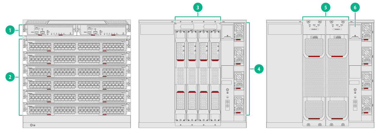
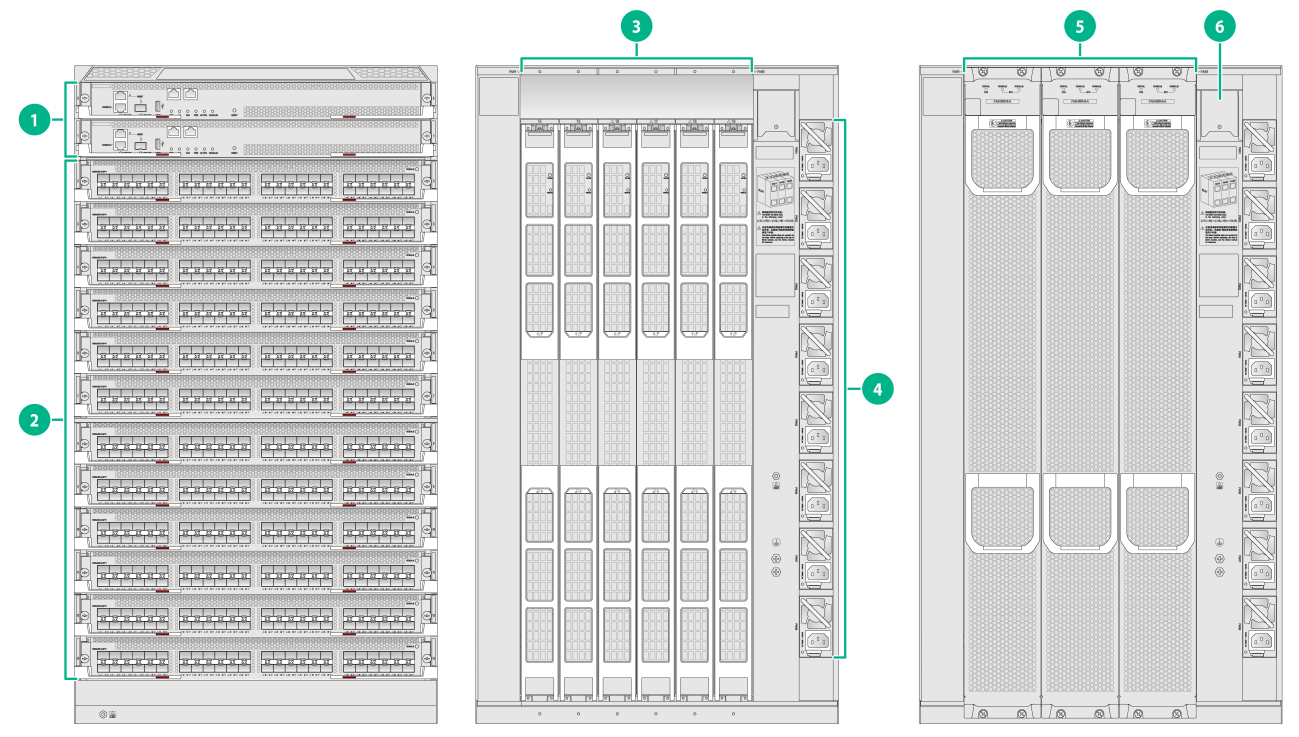
Figure 1 S10506X-G front and rear panels
|
(1) MPU section |
(2) Service module section |
|
(3) Switch fabric module section |
(4) Power supply section |
|
(5) Fan tray section |
(6) Power switches |
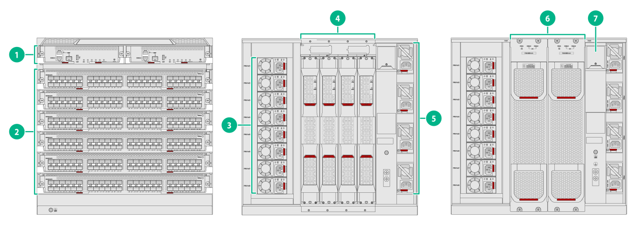
Figure 2 S10506X-G-PoE switch front and rear panels
|
(1) MPU section |
(2) Service module section |
|
(3) PoE power supply section |
(4) Switch fabric module section |
|
(5) Power supply section |
(6) Fan tray section |
|
(7) Power switches |
|
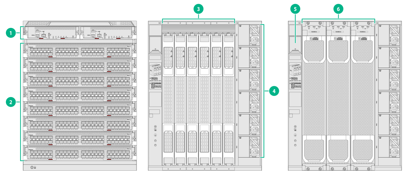
Figure 3 S10508X-G switch front and rear panels
|
(1) MPU section |
(2) Service module section |
|
(3) Switch fabric module section |
(4) Power supply section |
|
(5) Power switches |
(6) Fan tray section |
Figure 4 S10512X-G front and rear panels
|
(1) MPU section |
(2) Service module section |
|
(3) Switch fabric module section |
(4) Power supply section |
|
(5) Fan tray section |
(6) Power switches |
The switch has an MPU section, service module section, switch fabric module section, power supply section, and fan tray section. You must configure components in these sections.
Table 1 Description for the switch sections
|
Section |
Installation description |
|
MPU section |
No MPUs are provided with the switch. The switch has two MPU slots. You can install one MPU, or two MPUs for redundancy. To install only one MPU for the switch, you can install it in either of the MPU slots. Install a filler panel in the empty MPU slot. |
|
Service module section |
No service modules are provided with the switch. · S10506X-G/S10506X-G-PoE—6 service module slots. Select the service module model and quantity as are needed. · S10508X-G—8 service module slots. Select the service module model and quantity as are needed. · S10512X-G—12 service module slots. Select the service module model and quantity as needed. You can install a service module in any of the service module slots. Install a filler panel in each empty service module slot. |
|
Power supply section |
No power supplies are provided with the switch. · S10506X-G—4 power supply slots, on the right side of the rear panel. · S10506X-G-PoE—4 power supply slots and 8 PoE power supply slots on the left and rights sides of the rear panel. · S10508X-G—6 power supply slots, on the right side of the rear panel. · S10512X-G—8 power supply slots, on the right side of the rear panel. The switch supports N+N (dual power inputs) and N+1 (single power input) power redundancy. Determine the number of power supplies based on power supply mode and the system power consumption. You can install a power supply in any of the power supply slots. Install a filler panel in each empty power supply slot. |
|
Switch fabric module section |
No switch fabric modules are provided with the switch. · S10506X-G/S10506X-G-PoE—Install 1 to 4 switch fabric modules. · S10508X-G—Install 1 to 6 switch fabric modules. · S10512X-G—Install 1 to 6 switch fabric modules. Install a filler panel in each empty switch fabric module slot. Read the priority instructions about switch fabric module slots on the rear panel of the chassis. Insert switch fabric modules according to the priorities. Each fan tray covers two switch fabric module slots. Before you replace a switch fabric module, remove the fan tray that covers it. |
|
Fan tray section |
No fan trays are provided with the switch. · S10506X-G/S10506X-G-PoE—Two fan tray slots FAN 1 and FAN 2. · S10508X-G—Three fan tray slots FAN 1, FAN 2, and FAN 3. · S10512X-G—Three fan tray slots FAN 1, FAN 2, and FAN 3. You must install a fan tray in each slot. |
|
Power switches |
To power on the switch, turn on both power switches. To power off the switch, turn off both power switches. |
Slot arrangement
Table 2 Slot quantity for the removable components
|
Item |
S10506X-G |
S10506X-G-PoE |
S10508X-G |
S10512X-G |
|
MPU slots |
2 |
2 |
2 |
2 |
|
Service module slots |
6 |
6 |
8 |
12 |
|
Switch fabric module slots |
4 |
4 |
6 |
6 |
|
Power supply slots |
4 |
4+8 |
6 |
8 |
|
Fan tray slots |
2 |
2 |
3 |
3 |
Figure 5 S10506X-G switch slot arrangement
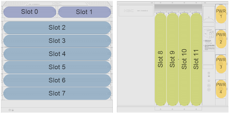
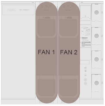

Figure 6 S10506X-G-PoE switch slot arrangement
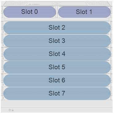

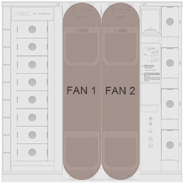

Figure 7 S10508X-G switch slot arrangement
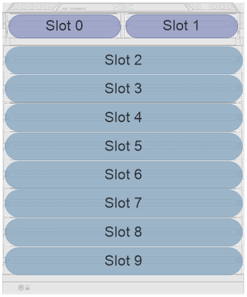
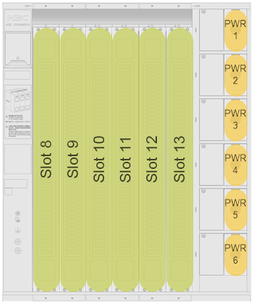
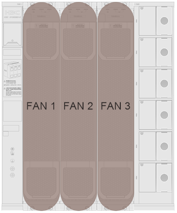

Figure 8 S105012X-G switch slot arrangement
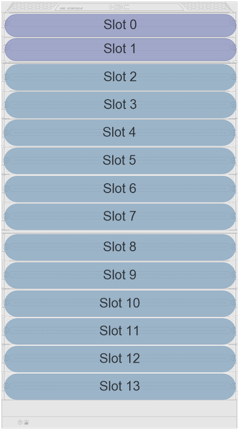
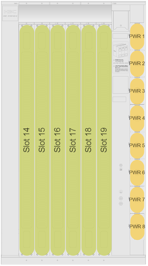
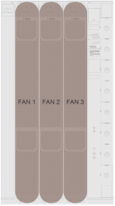

Table 3 describes the slots for the removable components.
Table 3 Slots for the removable components
|
Model |
MPU |
Service module |
Switch fabric module |
Power supply |
Fan tray |
|
S10506X-G |
Slots 0 and 1 |
Slots 2 to 7 |
Slots 8 to 11 Slots 8 and 9 are covered by FAN 1. Slots 10 and 11 are covered by FAN 2. |
PWR 1 to PWR 4 |
FAN 1 and FAN 2 |
|
S10506X-G-PoE |
Slots 0 and 1 |
Slots 2 to 7 |
Slots 8 to 11 Slots 8 and 9 are covered by FAN 1. Slots 10 and 11 are covered by FAN 2. |
· PWR 1 to PWR 4 · PWR-PoE 1 to PWR-PoE 8 |
FAN 1 and FAN 2 |
|
S10508X-G |
Slots 0 and 1 |
Slots 2 to 9 |
Slots 10 to 15 Slots 10 and 11 are covered by FAN 1. Slots 12 and 13 are covered by FAN 2. Slots 14 and 15 are covered by FAN 3. |
PWR 1 to PWR 6 |
FAN 1 to FAN 3 |
|
S10512X-G |
Slots 0 and 1 |
Slots 2 to 13 |
Slots 14 to 19 Slots 14 and 15 are covered by FAN 1. Slots 16 and 17 are covered by FAN 2. Slots 18 and 19 are covered by FAN 3 |
PWR 1 to PWR 8 |
FAN 1 to FAN 3 |
Chassis specifications
Table 4 Chassis specifications
|
Item |
S10506X-G |
S10506X-G-PoE |
S10508X-G |
S10512X-G |
|
Power supply mode |
· AC · Low-voltage DC · High-voltage DC |
· AC · Low-voltage DC · High-voltage DC |
· AC · Low-voltage DC · High-voltage DC |
· AC · Low-voltage DC · High-voltage DC |
|
Certification |
· Safety regulations · EMC standards |
· Safety regulations · EMC standards |
· Safety regulations · EMC standards |
· Safety regulations · EMC standards |
|
MPU redundancy |
1+1 |
1+1 |
1+1 |
1+1 |
|
Switch fabric module redundancy |
N+M |
N+M |
N+M |
N+M |
|
Power supply redundancy |
· N+N · N+1 |
· N+N · N+1 |
· N+N · N+1 |
· N+N · N+1 |
|
Heat dissipation |
Air cooling |
Air cooling |
Air cooling |
Air cooling |
|
Maximum number of 400GE ports |
12 |
12 |
16 |
24 |
|
Maximum number of 100GE ports |
216 |
216 |
288 |
432 |
|
Maximum number of 40GE ports |
216 |
216 |
288 |
432 |
|
Maximum number of 25GE ports |
288 |
288 |
384 |
576 |
|
Maximum number of 10GE ports |
288 |
288 |
384 |
576 |
|
Maximum number of GE ports |
288 |
288 |
384 |
576 |
Weights and dimensions
Table 5 Chassis weights and dimensions
|
Model |
Net weight (excluding packaging) |
Net weight (including packaging) |
Max weight (fully configured) |
Height |
Width |
Depth |
|
S10506X-G |
30.5 kg (67.24 lb) |
39.0 kg (85.98 lb) |
< 85 kg (187.39 lb) |
Excluding packaging |
||
|
442 mm (17.40 in)/10 RU |
440 mm (17.32 in) |
520 mm (20.47 in) |
||||
|
Including packaging |
||||||
|
615 mm (24.21 in) |
690 mm (27.17 in) |
795 mm (31.30 in) |
||||
|
S10506X-G-PoE |
33.0 kg (72.75 lb) |
40.5 kg (89.29 lb) |
< 95 kg (209.44 lb) |
Excluding packaging |
||
|
442 mm (17.40 in)/10 RU |
440 mm (17.32 in) |
520 mm (20.47 in) |
||||
|
Including packaging |
||||||
|
615 mm (24.21 in) |
690 mm (27.17 in) |
795 mm (31.30 in) |
||||
|
S10508X-G |
46.5 kg (102.51 lb) |
80.5 kg (177.47 lb) |
< 130 kg (286.60 lb) |
Excluding packaging |
||
|
531 mm (20.91 in)/12 RU |
440 mm (17.32 in) |
640 mm (25.20 in) |
||||
|
Including packaging |
||||||
|
890 mm (35.04 in) |
750 mm (29.53 in) |
950 mm (37.40 in) |
||||
|
S10512X-G |
58.5 kg (128.97 lb) |
95.0 kg (209.44 lb) |
< 180 kg (396.83 lb) |
Excluding packaging |
||
|
796 mm (31.34 in)/18 RU |
440 mm (17.32 in) |
640 mm (25.20 in) |
||||
|
Including packaging |
||||||
|
1158 mm (45.59 in) |
750 mm (29.53 in) |
950 mm (37.40 in) |
||||
|
|
NOTE: · Rack Unit (RU) is a measurement unit used to indicate the height of a rack. 1 RU is equal to 44.45 mm (1.75 in). · Table 3 lists dimensions for the switch, excluding the mounting brackets, cable management brackets, modules, and power supplies. |
Total power consumption
The total power consumption of a switch is the sum of the power consumptions of all running modules and fan trays, depending on the type and quantity of the modules installed and the power consumption of the fan trays. The total power consumption can be calculated as follows:
· Minimum total power consumption of the switch = Minimum total power consumption of the modules + minimum power consumption of the fan trays.
· Typical total power consumption of the switch = Typical total power consumption of the modules + typical power consumption of the fan trays.
· Maximum total power consumption of the switch = Maximum total power consumption of the modules + maximum power consumption of the fan trays.
For example, for an S10506X-G switch that has two LSEM1SUPA0 MPUs, two LSEM1GT48TSSD0 service modules, two LSEM1SF06D0 switch fabric modules, and two FAN-80B-4-A fan trays:
· The minimum total power consumption of the switch is 2 × 22 + 2 × 28 + 2 × 55 + 2 × 30 = 270 W.
· The typical total power consumption of the switch is 2 × 23 + 2 × 47 + 2 × 63 + 2 × 100 = 466 W.
· The maximum total power consumption of the switch is 2 × 30 + 2 × 55 + 2 × 95 + 2 × 230 = 820 W.
Heat dissipation
Heat dissipation is measured in BTU/h, and 1 W equals 3.4121 BTU/h.
The heat dissipation of a switch depends on its power consumption. To calculate heat dissipation of the switch, assume 90% power consumption is converted to heat, and the conversion efficiency of the power supplies is 90%. Heat dissipation/hour of the switch is [ 0.9 × (total power consumption of the modules plus power consumption of the fan trays) ] /0.9 × 3.4121.
Table 6 Heat dissipation
|
Switch module |
Heat dissipation (BTU/H) |
|
S10506X-G/S10506X-G-PoE |
10216 |
|
S10508X-G |
14843 |
|
S10512X-G |
121405 |
Cooling
For adequate ventilation and heat dissipation, make sure the following requirements are met:
· Make sure the airflow of the chassis matches the airflow direction of the installation site.
· Reserve a minimum clearance of 30 cm (11.81 in) around the inlet and outlet air vents.
· Make sure the rack for the switch has a good cooling system.
· Make sure the installation site has a good cooling system.
Figure 9 Airflow through an S10506X-G switch
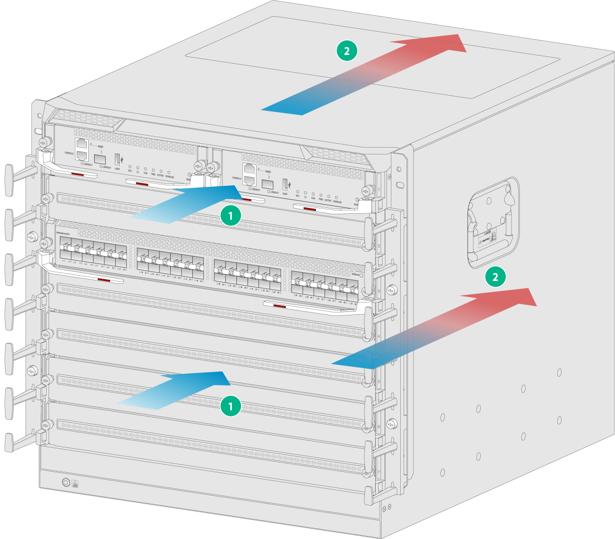
|
(1) Chassis air intake direction |
(2) Chassis air outlet direction |
Availability and reliability
Table 7 S10500X-G switch availability and reliability
|
Switch model |
Availability |
Availability Mean Time Between Failures (MTBF) |
Mean Time To Repair (MTTR) |
|
S10506X-G/S10506X-G-PoE |
0.9999984 |
36.5 years |
0.5 hours |
|
S10508X-G |
0.999998 |
32.5 years |
0.5 hours |
|
S10512X-G |
0.9999973 |
21.0 years |
0.5 hours |
Environmental specifications
Table 8 Environmental specifications
|
Description |
Operating |
Storage |
|
Temperature |
0°C to 45°C (32°F to 113°F) |
–40°C to +70°C (–40°F to +158°F) |
|
Relative humidity (noncondensing) |
5% to 95% |
5% to 95% |
|
Altitude |
–60 m to +5000 m (–196.85 ft to +16404.20 ft) From 0 m (0 ft), the maximum operating temperature decreases by 0.33°C (32.59°F) for every 100 m (328.084 ft) increase in altitude. |
–60 m to +5000 m (–196.85 ft to +16404.20 ft) |
Noise
The switch uses fan trays that can automatically adjust the fan speed based on the switch temperature. The sound pressure levels vary by fan speed. For more information, see Table 11.
|
Switch model |
Fan tray model |
Sound pressure level in the acceptable temperature range |
Sound pressure level when the fan tray operates at full speed |
|
S10506X-G/S10506X-G-PoE (fully configured with fan trays) |
FAN-80B-4-A |
57.7 dBA |
79.1 dBA |
|
S10508X-G (fully configured with fan trays) |
FAN-80B-5-A |
58.6 dBA |
81.9 dBA |
|
S10512X-G (fully configured with fan trays) |
FAN-80B-8-A |
62.1 dBA |
82.6 dBA |
|
|
NOTE: The sound pressure levels are measured based on the method specified in ISO 7779 at bystander positions. |
Rack
The switch can be installed in a 19-inch standard rack. For information about how to select and install a rack, see Universal Cabinet and Accessories Installation Guide.
Slide rails
No slide rails are shipped with the switch. Select slide rails for the switch as required. Table2-5 describes the slide rails available for the switch.
Table 10 Slide rails available for the switch
|
Item |
LSEM1BSR |
RL-1U-A |
LSXM1BSR |
|
Part No. |
0231AJAP |
0231AJE5 |
0231A4EK |
|
Adjustment range |
380 mm to 630 mm (14.96 in to 24.80 in) |
380 mm to 630 mm (14.96 in to 24.80 in) |
630 mm to 900 mm (24.80 in to 35.43 in) |
|
Load bearing capacity |
100 kg (220.46 lb) |
200 kg (440.92 lb) |
400 kg (881.83 lb) |
|
Occupied space |
N/A |
1 U |
1 U |
|
Applicable rack depth |
0.6 m (1.97 ft), 0.8 m (2.62 ft) |
0.6 m (1.97 ft), 0.8 m (2.62 ft) |
1.0 m (3.28 ft), 1.2 m (3.94 ft) |
|
Applicable switch model |
S10506X-G/S10506X-G-PoE |
All S10500X-G switch models |
All S10500X-G switch models |
|
|
NOTE: The applicable rack depths in Table2-5 are for your reference only. Before you install slide rails, make sure the rack depth is in the adjustment range of the slide rails. |
Modules
The switch supports varieties of modules that are different in power consumptions. For a same module, the power consumption varies by its state.
· The minimum power consumption of a module refers to the power consumed by the module when it is running with all its ports down and its fiber ports not installed with transceiver modules.
· The typical power consumption of a module refers to the power consumed by the module when it is running with 50% of its ports connected and at 50% load.
· The maximum power consumption of a module refers to the power consumed by the module when it is running with all of its ports connected and at full load.
|
|
NOTE: Module dimensions are expressed in the Height (H) × Width (W) × Depth (D) format: · Height—Height of the front panel of the module. · Width—Width of the front panel of the module. · Depth—Depth from the front panel of the module to the connector (Including the connector, but excluding the ejector levers and captive screws). |
|
|
NOTE: For transceiver modules and cables available for a module, see H3C S10500X-G Switch Series Cards and Transceiver Modules Compatibility Matrixes. |
Naming conventions
MPU naming conventions
Figure 10 MPU naming conventions
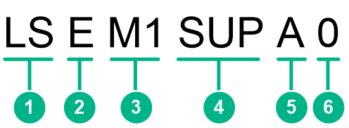
Table 11 MPU naming conventions
|
No. |
Description |
|
1 |
Product line. LS represents the switch product line. |
|
2 |
Product series. E represents the S10500X-G switch series. |
|
3 |
Distinguisher. |
|
4 |
Module type. Values include MPU, SRP, or SUP. |
|
5 |
MPU type. |
|
6 |
Extended attributes. |
Service module naming conventions
Figure 11 Service module naming conventions
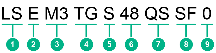
Table 12 Service module naming conventions
|
No. |
Description |
|
1 |
Product line. LS represents the switch product line. |
|
2 |
Product series. E represents the S10500X-G switch series. |
|
3 |
Distinguisher. |
|
4 |
Primary interface rate of the service module. |
|
5 |
Primary interface type of the service module. |
|
6 |
Primary interface quantity of the service module. |
|
7 |
Secondary interface type of the service module (optional). |
|
8 |
Service module type. |
|
9 |
Extended attributes. |
Switch fabric module naming conventions
Figure 12 Switch fabric module naming conventions
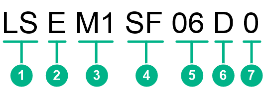
Table 13 Switch fabric module naming conventions
|
No. |
Description |
|
1 |
Product line. LS represents the switch product line. |
|
2 |
Product series. E represents the S10500X-G switch series. |
|
3 |
Distinguisher. |
|
4 |
Module type. SF represents the switch fabric module. |
|
5 |
Compatible switch model. 06 represents that the switch fabric module is compatible with the S10506X-G/S10506X-G-PoE switch. |
|
6 |
Switch fabric module type. |
|
7 |
Extended attributes. |
MPUs
|
|
IMPORTANT: · To verify compatibility of the module with the software release you are using, see the release notes. · The USB port on the MPU outs power in accordance with the USB 2.0 standard. Only a USB 2.0-compliant device can be installed in the USB port. A non-compliant USB 2.0 device might not be recognized. · Set the same speed and duplex mode for a management Ethernet port and its peer port. · If the two management ports are connected to one remote switch, you must assign their peer ports to different VLANs. Login or file transfer will fail if the peer ports are in the same VLAN. · When using the BootWare menu to upgrade software or BootWare, make sure you use 10/100/1000BASE-T port M0/0/0 for image transfer. |
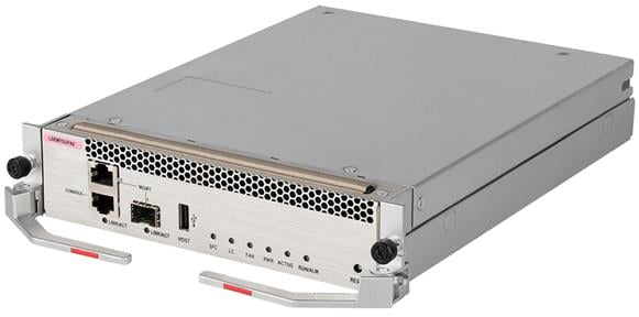
LSEM1SUPA0/LSEM3SUPA0
View
The LSEM1SUPA0 and LSEM3SUPA0 are MPUs available for the S10506X-G, S10506X-G-PoE, and S10508X-G switches. MPUs are the core component of the system control plane.
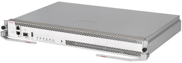
Figure 13 LSEM1SUPA0/LSEM3SUPA0 MPU view (LSEM1SUPA0 as an example)
Technical specifications
LSEM1SUPA0/LSEM3SUPA0 MPU technical specifications
|
Item |
LSEM1SUPA0 |
LSEM3SUPA0 |
|
Net weight |
1.90 kg (4.19 lb) |
1.95 kg (4.30 lb) |
|
Dimensions (H × W × D) |
51 × 423 × 270 mm (2.01 × 16.65 × 10.63 in) |
|
|
Power consumption |
· Minimum: 22 W · Typical: 23 W · Maximum: 30 W |
· Minimum: 22 W · Typical: 23 W · Maximum: 33 W |
|
Processor |
Quad-core, 1.8 GHz |
Quad-core, 2.2 GHz |
|
SDRAM |
8 GB |
|
|
Flash |
8 GB |
2 GB |
|
NVRAM |
1 MB |
|
|
Connector type |
· RJ-45 · LC · USB (Type A) |
|
|
Ports |
· 1 × console port · 1 × USB port · 2 × network management ports (one RJ-45 port and one SFP port) |
|
|
Port transmission speed |
· Console port: 9600 bps (default) to 115200 bps · RJ-45 management port: 10/100/1000 Mbps, half/full duplex · SFP management port: 1000 Mbps |
|
|
Hot swapping |
Supported |
|
|
Applicable switch models |
S10506X-G/S10506X-G-PoE/S10508X-G |
|
Ports and LEDs
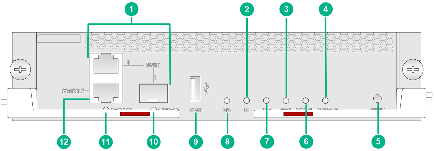
Figure 14 LSEM1SUPA0/LSEM3SUPA0 front panel
|
(1) Network management ports |
(2) Service module status LED (LC) |
|
(3) MPU active/standby status LED (ACTIVE) |
(4) MPU status LED (RUN/ALM) |
|
(5) Reset button |
(6) Power supply status LED (PWR) |
|
(7) Fan tray status LED (FAN) |
(8) Switch fabric module status LED (SFC) |
|
(9) USB port |
(10) SFP management Ethernet port LED |
|
(11) 10/100/1000BASE-T management Ethernet port LED |
(12) Console port |
|
LED |
Status |
Description |
|
Management Ethernet port LED |
Flashing |
The port is in sending or receiving data. |
|
On |
A link is present on the port. |
|
|
Off |
No link is present on the port. |
|
|
Fan tray status LED |
Steady green |
All fan trays are present and operating correctly. |
|
Steady red |
A fan tray is faulty, or no or only one fan tray is operating correctly. |
|
|
Off |
The switch has not been powered on. |
|
|
Power supply status LED |
Steady green |
All present power supplies are operating correctly. |
|
Steady red |
One or more power supplies are faulty. |
|
|
Off |
The switch has not been powered on. |
|
|
Service module status LED |
Flashing green (once per two seconds) |
All present service modules are operating correctly. |
|
Steady red |
· One or more service modules are starting up or loading software. · One or more service modules are faulty, or a high severity alarm has occurred on one or more service modules. · The temperature of a service module has exceeded the upper warning threshold or fell below the lower warning threshold. |
|
|
Off |
No service module is present. |
|
|
MPU status LED |
Flashing green (once per two seconds) |
The MPU is operating correctly. |
|
Flashing green (four times per second) |
The MPU is loading software. |
|
|
Steady green |
The MPU is starting up. |
|
|
Steady red |
A high severity alarm has occurred on the MPU, or the MPU is faulty. |
|
|
Flashing red (once per four seconds) |
The MPU temperature has exceeded the upper warning threshold or fell below the lower warning threshold. |
|
|
Off |
The MPU is not present or the MPU is faulty. |
|
|
MPU active/standby status LED |
Steady green |
The MPU is in active state. |
|
Off |
· The MPU is in standby state. · The MPU is faulty. To further determine the MPU status, examine the MPU status LED. |
|
|
Switch fabric module status LED |
Flashing green (once per two seconds) |
The switch fabric module is operating correctly. |
|
Steady green |
One or more switch fabric modules have been isolated. |
|
|
Steady red |
· One or more switch fabric modules are starting up or loading software. · One or more switch fabric modules are faulty, or a high severity alarm has occurred on one or more service modules. · The temperature of a switch fabric module has exceeded the upper warning threshold or fell below the lower warning threshold. |
|
|
NOTE: · You can identify the rate of a management Ethernet port by observing the color of its LED. When the LED is green, the management Ethernet port is operating at 1 Gbps. When the LED is yellow, the management Ethernet port is operating at 100/10 Mbps. · The power supply status LED is steady green only when all the power supplies are operating correctly. When a power supply is faulty, the power supply status LED is steady red. · If an isolation of a switch fabric module occurs simultaneously with a higher severity alarm on another switch fabric module, the switch fabric module LED on the MPU is steady red to indicate the higher severity alarm. |
Table 16 Button description
|
Button mark |
Name |
Description |
|
RESET |
Reset button |
To reset the MPU, press the reset button. In a single MPU configuration, pressing the reset button on the MPU triggers not only a reset of the MPU but also a restart of the entire device. In a dual-MPU configuration, pressing the reset button on the active MPU triggers an active/standby MPU switchover. If you press the reset button on the standby MPU, only the standby MPU will be reset without causing the entire device to restart. |
LSEM1SUPB0/LSEM3SUPB0
View
The LSEM1SUPB0 and LSEM3SUPB0 are MPUs available for the S10512X-G switch. MPUs are the core component of the system control plane.
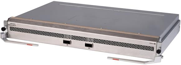
Figure 15 LSEM1SUPB0/LSEM3SUPB0 MPU view (LSEM1SUPB0 as an example)
Technical specifications
Table 17 LSEM1SUPB0/LSEM3SUPB0 technical specifications
|
Item |
LSEM1SUPB0 |
LSEM3SUPB0 |
|
Net weight |
3.00 kg (6.62 lb) |
2.95 kg (6.50 lb) |
|
Dimensions (H × W × D) |
51 × 423 × 270 mm (2.01 × 16.65 × 10.63 in) |
|
|
Power consumption |
· Minimum: 22 W · Typical: 23 W · Maximum: 30 W |
· Minimum: 22 W · Typical: 23 W · Maximum: 30 W |
|
Processor |
Quad-core, 1.8 GHz |
Quad-core, 2.2 GHz |
|
SDRAM |
8 GB |
|
|
Flash |
8 GB |
2 GB |
|
NVRAM |
1 MB |
|
|
Connector type |
· RJ-45 · LC · USB (Type A) |
|
|
Ports |
· 1 × console port · 1 × USB port · 2 × network management ports (one RJ-45 port and one SFP port) |
|
|
Port transmission speed |
· Console port: 9600 bps (default) to 115200 bps · RJ-45 management port: 10/100/1000 Mbps, half/full duplex · SFP management port: 1000 Mbps |
|
|
Hot swapping |
Supported |
|
|
Applicable switch models |
S10512X-G |
|
Ports and LEDs
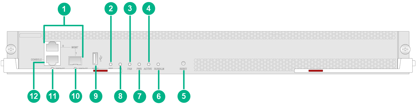
Figure 16 LSEM1SUPB0/LSEM3SUPB0 front panel
|
(1) Network management ports |
(2) Switch fabric module status LED (SFC) |
|
(3) Fan tray status LED (FAN) |
(4) MPU active/standby status LED (ACTIVE) |
|
(5) Reset button |
(6) MPU status LED (RUN/ALM) |
|
(7) Power supply status LED (PWR) |
(8) Service module status LED (LC) |
|
(9) USB port |
(10) SFP management Ethernet port LED |
|
(11) 10/100/1000BASE-T management Ethernet port LED |
(12) Console port |
|
LED |
Status |
Description |
|
Management Ethernet port LED |
Flashing |
The port is in sending or receiving data. |
|
On |
A link is present on the port. |
|
|
Off |
No link is present on the port. |
|
|
Fan tray status LEDs |
Steady green |
All fan trays are present and operating correctly. |
|
Steady red |
A fan tray is faulty, or no or only one fan tray is operating correctly. |
|
|
Off |
The switch has not been powered on. |
|
|
Power supply status LED |
Steady green |
All present power supplies are operating correctly. |
|
Steady red |
One or more power supplies are faulty. |
|
|
Off |
The switch has not been powered on. |
|
|
Service module status LED |
Flashing green (once per two seconds) |
All present service modules are operating correctly. |
|
Steady red |
· One or more service modules are starting up or loading software. · One or more service modules are faulty, or a high severity alarm has occurred on one or more service modules. · The temperature of a service module has exceeded the upper warning threshold or fell below the lower warning threshold. |
|
|
Off |
No service module is present. |
|
|
MPU status LED |
Flashing green (once per two seconds) |
The MPU is operating correctly. |
|
Flashing green (four times per second) |
The MPU is loading software. |
|
|
Steady green |
The MPU is starting up. |
|
|
Steady red |
A high severity alarm has occurred on the MPU, or the MPU is faulty. |
|
|
Flashing red (once per four seconds) |
The MPU temperature is abnormal. The temperature has exceeded the upper warning temperature threshold or dropped below the lower temperature threshold. |
|
|
Off |
The MPU is not present or the MPU is faulty. |
|
|
MPU active/standby status LED |
Steady green |
The MPU is in active state. |
|
Off |
The following are the possible causes: · The MPU is in standby state. · The MPU has failed. To further determine the MPU status, see the MPU status LED. |
|
|
Switch fabric module status LED |
Flashing green (once per two seconds) |
The switch fabric modules are operating correctly. |
|
Steady green |
One or more switch fabric modules have been isolated. |
|
|
Steady red |
· One or more switch fabric modules are starting up or loading software. · One or more switch fabric modules are faulty, or a high severity alarm has occurred on one or more service modules. · The temperature of a switch fabric module has exceeded the upper warning threshold or fell below the lower warning threshold. |
|
|
NOTE: · You can identify the rate of a management Ethernet port by observing the color of its LED. When the LED is green, the management Ethernet port is operating at 1 Gbps. When the LED is yellow, the management Ethernet port is operating at 100/10 Mbps. · The power supply status LED is steady green only when all the power supplies are operating correctly. When a power supply is faulty, the power supply status LED is steady red. · If an isolation of a switch fabric module occurs simultaneously with a higher severity alarm on another switch fabric module, the switch fabric module LED on the MPU is steady red to indicate the higher severity alarm. |
Table 19 Button description
|
Button mark |
Name |
Description |
|
RESET |
Reset button |
To reset the MPU, press the reset button. In a single MPU configuration, pressing the reset button on the MPU triggers not only a reset of the MPU but also a restart of the entire device. In a dual-MPU configuration, pressing the reset button on the active MPU triggers an active/standby MPU switchover. If you press the reset button on the standby MPU, only the standby MPU will be reset without causing the entire device to restart. |
400G interface modules
LSEM1CDQ2SF0/LSEM3CDQ2SF0
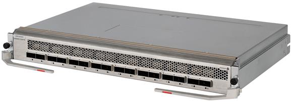
View
Figure 17 LSEM1CDQ2SF0/LSEM3CDQ2SF0 interface module view (LSEM1CDQ2SF0 as an example)
Technical specifications
Table 20 LSEM1CDQ2SF0/LSEM3CDQ2SF0 technical specifications
|
Item |
LSEM1CDQ2SF0 |
LSEM3CDQ2SF0 |
|
Net weight |
3.30 kg (7.28 lb) |
3.95 kg (8.71 lb) |
|
Dimensions (H × W × D) |
51 × 423 × 270 mm (2.01 × 16.65 × 10.63 in) |
|
|
Power consumption |
· Minimum: 67 W · Typical: 93 W · Maximum: 133 W |
· Minimum: 67 W · Typical: 93 W · Maximum: 136 W |
|
Port quantity |
2 |
|
|
Port type |
400GBASE-R-QSFP-DD fiber port |
|
|
Transceiver modules supported |
· QSFP-DD transceiver module · QSFP-DD DAC cable · QSFP-56 transceiver module · QSFP28 transceiver module · QSFP28 DAC cable · QSFP28 AOC cable · QSFP+ transceiver module · QSFP+ DAC cable · QSFP+ AOC cable |
|
|
Services |
Provides data access and switching with two 100GE fiber ports. |
|
|
Hot swapping |
Supported |
|
Ports and LEDs
Figure 18 LSEM1CDQ2SF0/LSEM3CDQ2SF0 front panel
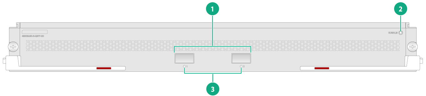
|
(1) 400GBASE-R-QSFP-DD fiber ports |
(2) RUN/ALM LED |
|
(3) 400GBASE-R-QSFP-DD fiber port LEDs |
|
Table 21 LED description
|
LED |
Status |
Description |
|
QSFP-DD fiber port LED |
Flashing |
The QSFP-DD port is sending or receiving data. |
|
On |
A link is present on the QSFP-DD port. |
|
|
Off |
No link is present on the QSFP-DD port. |
|
|
RUN/ALM LED |
Flashing green (once per two seconds) |
The interface module is operating correctly. |
|
Flashing green (four times per second) |
The interface module is loading software. |
|
|
Steady green |
The interface module is starting up. |
|
|
Steady red |
The interface module is faulty, or a high severity alarm has occurred on the interface module. |
|
|
Flashing red (once per four seconds) |
The temperature of the interface module has exceeded the upper warning threshold or fell below the lower warning threshold. |
|
|
Off |
The interface module is faulty or not present. |
100G interface modules
LSEM1CGQ16SF0/LSEM3CGQ16SF0
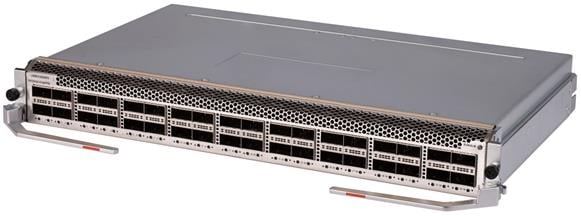
View
Figure 19 LSEM1CGQ16SF0/LSEM3CGQ16SF0 interface module view (LSEM1CGQ16SF0 as an example)
Technical specifications
Table 22 LSEM1CGQ16SF0/LSEM3CGQ16SF0 technical specifications
|
Item |
LSEM1CGQ16SF0 |
LSEM3CGQ16SF0 |
|
Net weight |
3.95 kg (8.71 lb) |
|
|
Dimensions (H × W × D) |
51 × 423 × 270 mm (2.01 × 16.65 × 10.63 in) |
|
|
Power consumption |
· Minimum: 70 W · Typical: 96 W · Maximum: 197 W |
· Minimum: 70 W · Typical: 96 W · Maximum: 200 W |
|
Port quantity |
16 |
|
|
Port type |
100GBASE-R-QSFP28 fiber ports |
|
|
Transceiver modules supported |
· QSFP28 transceiver module · QSFP28 DAC cable · QSFP28 AOC cable · QSFP+ transceiver module · QSFP+ DAC cable · QSFP+ AOC cable · QSFP28 to SFP28 DAC cable · QSFP+ to SFP+ DAC cable |
|
|
Services |
Provides data access and switching with sixteen 100GE fiber ports. |
|
|
Hot swapping |
Supported |
|
Ports and LEDs
Figure 20 LSEM1CGQ16SF0/LSEM3CGQ16SF0 front panel
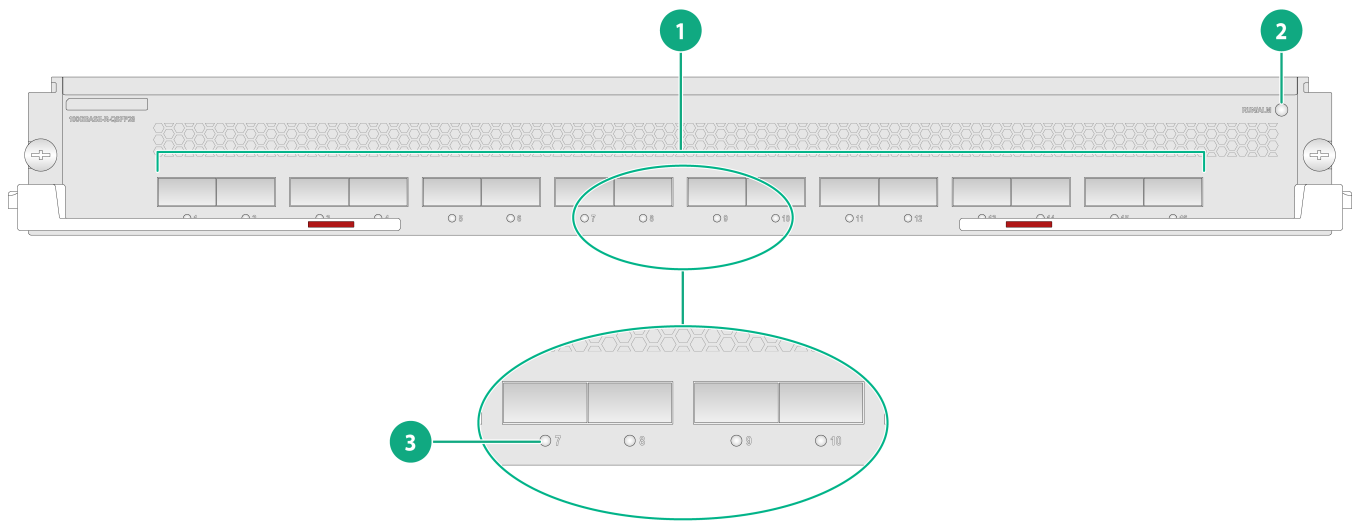
|
(1) 100GBASE-R-QSFP28 fiber ports |
(2) RUN/ALM LED |
|
(3) 100GBASE-R-QSFP28 fiber port LEDs |
|
Table 23 LED description
|
LED |
Status |
Description |
|
QSFP28 port LED |
Flashing |
The QSFP28 port is sending or receiving data. |
|
On |
A link is present on the QSFP28 port. |
|
|
Off |
No link is present on the QSFP28 port. |
|
|
RUN/ALM LED |
Flashing green (once per two seconds) |
The interface module is operating correctly. |
|
Flashing green (four times per second) |
The interface module is loading software. |
|
|
Steady green |
The interface module is starting up. |
|
|
Steady red |
The interface module is faulty, or a high severity alarm has occurred on the interface module. |
|
|
Flashing red (once per four seconds) |
The temperature of the interface module has exceeded the upper warning threshold or fell below the lower warning threshold. |
|
|
Off |
The interface module is faulty or not present. |
LSEM1CGQ36SF0/LSEM3CGQ36SF0
View
Figure 21 LSEM1CGQ36SF0/LSEM3CGQ36SF0 interface module view (LSEM1CGQ36SF0 as an example)
Technical specifications
Table 24 LSEM1CGQ36SF0/LSEM3CGQ36SF0 technical specifications
|
Item |
LSEM1CGQ36SF0 |
LSEM3CGQ36SF0 |
|
Net weight |
4.45 kg (9.81 lb) |
4.35 kg (9.59 lb) |
|
Dimensions (H × W × D) |
51 × 423 × 270 mm (2.01 × 16.65 × 10.63 in) |
|
|
Power consumption |
· Minimum: 121 W · Typical: 154 W · Maximum: 348 W |
· Minimum: 121 W · Typical: 154 W · Maximum: 351 W |
|
Port quantity |
36 |
|
|
Port type |
100GBASE-R-QSFP28 fiber port |
|
|
Transceiver modules supported |
· QSFP28 transceiver module · QSFP28 DAC cable · QSFP28 AOC cable · QSFP+ transceiver module · QSFP+ DAC cable · QSFP+ AOC cable · QSFP28 to SFP28 DAC cable · QSFP+ to SFP+ DAC cable |
|
|
Services |
Provides data access and switching with thirty-six 100GE fiber ports. |
|
|
Hot swapping |
Supported |
|
Ports and LEDs
Figure 22 LSEM1CGQ36SF0/LSEM3CGQ36SF0 front panel
|
(1) 100GBASE-R-QSFP28 fiber ports |
(2) RUN/ALM LED |
|
(3) 100GBASE-R-QSFP28 fiber port LEDs |
|
Table 25 LED description
|
LED |
Status |
Description |
|
QSFP28 port LED |
Flashing |
The QSFP28 port is sending or receiving data. |
|
On |
A link is present on the QSFP28 port. |
|
|
Off |
No link is present on the QSFP28 port. |
|
|
RUN/ALM LED |
Flashing green (once per two seconds) |
The interface module is operating correctly. |
|
Flashing green (four times per second) |
The interface module is loading software. |
|
|
Steady green |
The interface module is starting up. |
|
|
Steady red |
The interface module is faulty, or a high severity alarm has occurred on the interface module. |
|
|
Flashing red (once per four seconds) |
The temperature of the interface module has exceeded the upper warning threshold or fell below the lower warning threshold. |
|
|
Off |
The interface module is faulty or not present. |
40G interface modules
LSEM1QGS16SF0/LSEM3QGS16SF0
View
Figure 23 LSEM1QGS16SF0/LSEM3QGS16SF0 interface module view (LSEM1QGS16SF0 as an example)
Technical specifications
Table 26 LSEM1QGS16SF0/LSEM3QGS16SF0 technical specifications
|
Item |
LSEM1QGS16SF0 |
LSEM3QGS16SF0 |
|
Net weight |
3.95 kg (8.71 lb) |
4.05 kg (8.93 lb) |
|
Dimensions (H × W × D) |
51 × 423 × 270 mm (2.01 × 16.65 × 10.63 in) |
|
|
Power consumption |
· Minimum: 71 W · Typical: 83 W · Maximum: 172 W |
· Minimum: 71 W · Typical: 83 W · Maximum: 175 W |
|
Port quantity |
16 |
|
|
Port type |
40GBASE-R-QSFP+ fiber ports |
|
|
Transceiver modules supported |
· QSFP+ transceiver module · QSFP+ DAC cable · QSFP+ AOC cable · QSFP+ to SFP+ DAC cable |
|
|
Services |
Provides data access and switching with sixteen 40G fiber ports. |
|
|
Hot swapping |
Supported |
|
Ports and LEDs
Figure 24 LSEM1QGS16SF0/LSEM3QGS16SF0 front panel

|
(1) 40GBASE-R-QSFP+ fiber ports |
(2) RUN/ALM LED |
|
(3) 40GBASE-R-QSFP fiber port LEDs |
|
Table 27 LED description
|
LED |
Status |
Description |
|
QSFP28 port LED |
Flashing |
The QSFP28 port is sending or receiving data. |
|
On |
A link is present on the QSFP28 port. |
|
|
Off |
No link is present on the QSFP28 port. |
|
|
RUN/ALM LED |
Flashing green (once per two seconds) |
The interface module is operating correctly. |
|
Flashing green (four times per second) |
The interface module is loading software. |
|
|
Steady green |
The interface module is starting up. |
|
|
Steady red |
The interface module is faulty, or a high severity alarm has occurred on the interface module. |
|
|
Flashing red (once per four seconds) |
The temperature of the interface module has exceeded the upper warning threshold or fell below the lower warning threshold. |
|
|
Off |
The interface module is faulty or not present. |
|
|
NOTE: You can determine whether a QSFP28 port supports 100GE downspeed to 40GE by observing the color of its LED. If the LED is yellow, the QSFP28 port supports 100GE downspeed to 40GE. If the LED is green, the QSFP28 port does not support 100GE downspeed to 40GE. |
LSEM1QGS36SF0/LSEM3QGS36SF0
View
Figure 25 LSEM1QGS36SF0/LSEM3QGS36SF0 interface module view (LSEM1QGS36SF0 as an example)
Technical specifications
Table 28 LSEM1QGS36SF0/LSEM3QGS36SF0 technical specifications
|
Item |
LSEM1QGS36SF0 |
LSEM3QGS36SF0 |
|
Net weight |
4.45 kg (9.81 lb) |
4.40 kg (9.70 lb) |
|
Dimensions (H × W × D) |
51 × 423 × 270 mm (2.01 × 16.65 × 10.63 in) |
|
|
Power consumption |
· Minimum: 121 W · Typical: 141 W · Maximum: 312 W |
· Minimum: 121 W · Typical: 141 W · Maximum: 315 W |
|
Port quantity |
36 |
|
|
Port type |
40GBASE-R-QSFP+ fiber port |
|
|
Transceiver modules supported |
· QSFP+ transceiver module · QSFP+ DAC cable · QSFP+ AOC cable · QSFP+ to SFP+ DAC cable |
|
|
Services |
Provides data access and switching with thirty-six 40GE fiber ports. |
|
|
Hot swapping |
Supported |
|
Ports and LEDs
Figure 26 LSEM1QGS36SF0/LSEM3QGS36SF0 front panel

|
(1) 40GBASE-R-QSFP+ fiber ports |
(2) RUN/ALM LED |
|
(3) 40GBASE-R-QSFP fiber port LEDs |
|
Table 29 LED description
|
LED |
Status |
Description |
|
QSFP28 port LED |
Flashing |
The QSFP28 port is sending or receiving data. |
|
On |
A link is present on the QSFP28 port. |
|
|
Off |
No link is present on the QSFP28 port. |
|
|
RUN/ALM LED |
Flashing green (once per two seconds) |
The interface module is operating correctly. |
|
Flashing green (four times per second) |
The interface module is loading software. |
|
|
Steady green |
The interface module is starting up. |
|
|
Steady red |
The interface module is faulty, or a high severity alarm has occurred on the interface module. |
|
|
Flashing red (once per four seconds) |
The temperature of the interface module has exceeded the upper warning threshold or fell below the lower warning threshold. |
|
|
Off |
The interface module is faulty or not present. |
|
|
NOTE: You can determine whether a QSFP28 port supports 100GE downspeed to 40GE by observing the color of its LED. If the LED is yellow, the QSFP28 port supports 100GE downspeed to 40GE. If the LED is green, the QSFP28 port does not support 100GE downspeed to 40GE. |
25G interface modules
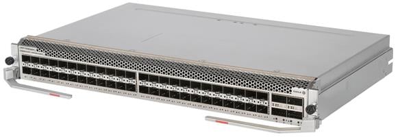
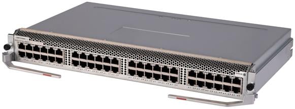
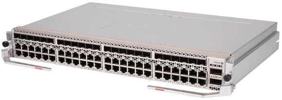
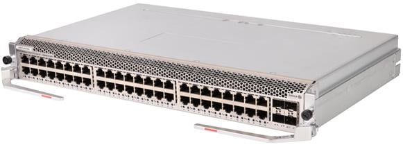
LSEM1YGS48CQSF0/LSEM3YGS48CQSF0
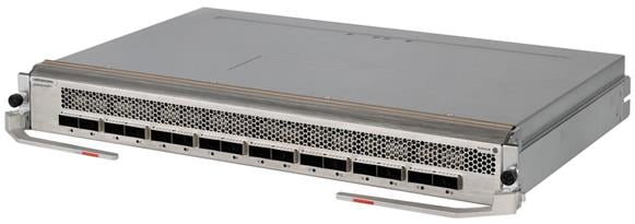
View
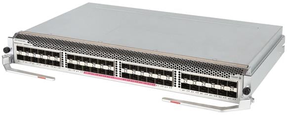
Figure 27 LSEM1YGS48CQSF0/LSEM3YGS48CQSF0 interface module view (LSEM1YGS48CQSF0 as an example)
Technical specifications
Table 30 LSEM1YGS48CQSF0/LSEM3YGS48CQSF0 technical specifications
|
Item |
LSEM1YGS48CQSF0 |
LSEM3YGS48CQSF0 |
|
Net weight |
4.20 kg (9.26 lb) |
4.30 kg (9.48 lb) |
|
Dimensions (H × W × D) |
51 × 423 × 270 mm (2.01 × 16.65 × 10.63 in) |
|
|
Power consumption |
· Minimum: 75 W · Typical: 103 W · Maximum: 218 W |
· Minimum: 75 W · Typical: 103 W · Maximum: 221 W |
|
Port quantity |
52 |
|
|
Port type |
· 100GBASE-R-QSFP28 fiber port · 25GBASE-R-SFP28 fiber port |
|
|
Transceiver modules supported |
· QSFP28 transceiver module · QSFP28 DAC cable · QSFP28 AOC cable · QSFP+ transceiver module · QSFP+ DAC cable · QSFP+ AOC cable · QSFP28 to SFP28 DAC cable · QSFP+ to SFP+ DAC cable · SFP28 transceiver module · SFP28 DAC cable · SFP28 AOC cable · 10G SFP+ transceiver module · 10G SFP+ DAC cable · 1G SFP transceiver module |
|
|
Services |
Provides data access and switching with four 100GE fiber ports and forty-eight 25GE fiber ports. |
|
|
Hot swapping |
Supported |
|
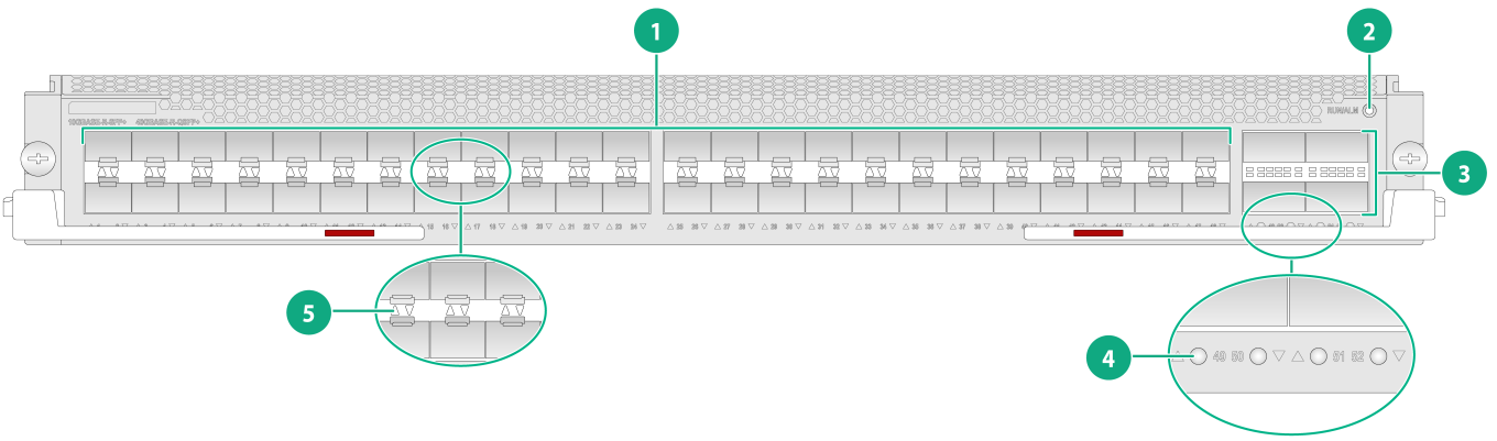
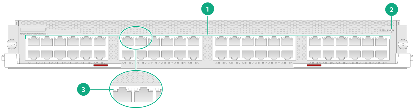
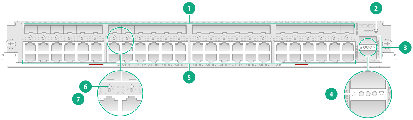
Ports and LEDs
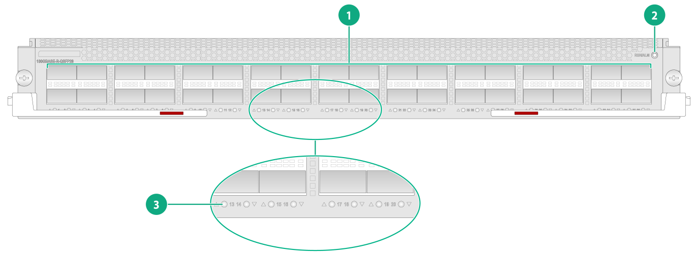
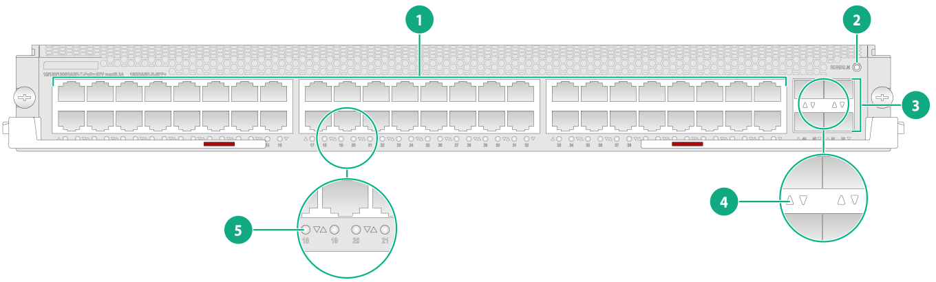
Figure 28 LSEM1YGS48CQSF0/LSEM3YGS48CQSF0 front panel
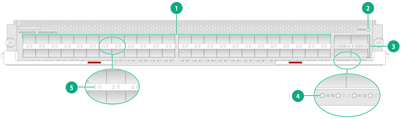
|
(1) 100GBASE-R-QSFP28 fiber ports |
(2) RUN/ALM LED |
|
(3) 25GBASE-R-SFP28 fiber ports |
(4) 25GBASE-R-SFP28 fiber port LEDs |
|
(5) 100GBASE-R-QSFP28 fiber port LEDs |
|
Table 31 LED description
|
LED |
Status |
Description |
|
QSFP28 port LED |
Flashing |
The QSFP28 port is sending or receiving data. |
|
On |
A link is present on the QSFP28 port. |
|
|
Off |
No link is present on the QSFP28 port. |
|
|
SFP28 port LED |
Flashing |
The SFP28 port is sending or receiving data. |
|
Steady on |
A link is present on the SFP28 port. |
|
|
Off |
No link is present on the SFP28 port. |
|
|
RUN/ALM LED |
Flashing green (once per two seconds) |
The interface module is operating correctly. |
|
Flashing green (four times per second) |
The interface module is loading software. |
|
|
Steady green |
The interface module is starting up. |
|
|
Steady red |
The interface module is faulty, or a high severity alarm has occurred on the interface module. |
|
|
Flashing red (once per four seconds) |
The temperature of the interface module has exceeded the upper warning threshold or fell below the lower warning threshold. |
|
|
Off |
The interface module is faulty or not present. |
10G interface modules
LSEM1TGS16GP32SD0
View
Figure 29 LSEM1TGS16GP32SD0 interface module view
Technical specifications
Table 32 LSEM1TGS16GP32SD0 interface module technical specifications
|
Item |
LSEM1TGS16GP32SD0 |
|
Net weight |
3.50 kg (7.72 lb) |
|
Dimensions (H × W × D) |
51 × 423 × 270 mm (2.01 × 16.65 × 10.63 in) |
|
Power consumption |
· Minimum: 39 W · Typical: 48 W · Maximum: 80 W |
|
Port quantity |
48 |
|
Port type |
· 10GBASE-R-SFP+ fiber port · 1000BASE-X-SFP port |
|
Transceiver modules supported |
· 10G SFP+ transceiver module · 10G SFP+ DAC cable · 100M/1G SFP transceiver module |
|
Services |
Provides data access and switching with sixteen 10GE fiber ports and thirty-two GE fiber ports. |
|
Hot swapping |
Supported |
Ports and LEDs
Figure 30 LSEM1TGS16GP32SD0 front panel

|
(1) 1000BASE-X-SFP ports |
(2) 10GBASE-R-SFP+ fiber ports |
|
(3) RUN/ALM LED |
(4) 10GBASE-R-SFP+ fiber port LEDs |
|
(5) 1000BASE-X-SFP port LEDs |
|
Table 33 LED description
|
LED |
Status |
Description |
|
SFP+ port LED |
Flashing |
The SFP+ port is sending or receiving data. |
|
On |
A link is present on the SFP+ port. |
|
|
Off |
No link is present on the SFP+ port. |
|
|
SFP port LED |
Flashing |
The SFP port is sending or receiving data. |
|
On |
A link is present on the SFP port. |
|
|
Off |
No link is present on the SFP port. |
|
|
RUN/ALM LED |
Flashing green (once per two seconds) |
The interface module is operating correctly. |
|
Flashing green (four times per second) |
The interface module is loading software. |
|
|
Steady green |
The interface module is starting up. |
|
|
Steady red |
The interface module is faulty, or a high severity alarm has occurred on the interface module. |
|
|
Flashing red (once per four seconds) |
The temperature of the interface module has exceeded the upper warning threshold or fell below the lower warning threshold. |
|
|
Off |
The interface module is faulty or not present. |
|
|
NOTE: You can identify the rate of an SFP+ port by observing the color of its LED. When the LED is green, the SFP+ port is operating at 10 Gbps. When the LED is yellow, the SFP+ port is operating at 1000 Mbps. |
LSEM1TGS24SD0
View
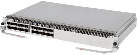
Figure 31 LSEM1TGS24SD0 interface module view
Technical specifications
Table 34 LSEM1TGS24SD0 technical specifications
|
Item |
LSEM1TGS24SD0 |
|
Net weight |
3.35 kg (7.39 lb) |
|
Dimensions (H × W × D) |
51 × 423 × 270 mm (2.01 × 16.65 × 10.63 in) |
|
Power consumption |
· Minimum: 24 W · Typical: 33 W · Maximum: 56 W |
|
Port quantity |
24 |
|
Port type |
10GBASE-R-SFP+ fiber port |
|
Transceiver modules supported |
· 10G SFP+ transceiver module · 10G SFP+ DAC cable · 1G SFP transceiver module |
|
Services |
Provides data access and switching with twenty-four 10GE fiber ports. |
|
Hot swapping |
Supported |
Ports and LEDs
Figure 32 LSEM1TGS24SD0 front panel
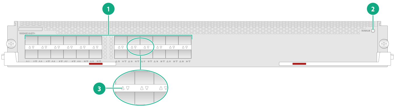
|
(1) 10GBASE-R-SFP+ fiber ports |
(2) RUN/ALM LED |
|
(3) 10GBASE-R-SFP+ fiber port LEDs |
|
Table 35 LED description
|
LED |
Status |
Description |
|
SFP+ port LED |
Flashing |
The SFP+ port is sending or receiving data. |
|
On |
A link is present on the SFP+ port. |
|
|
Off |
No link is present on the SFP+ port. |
|
|
RUN/ALM LED |
Flashing green (once per two seconds) |
The interface module is operating correctly. |
|
Flashing green (four times per second) |
The interface module is loading software. |
|
|
Steady green |
The interface module is starting up. |
|
|
Steady red |
The interface module is faulty, or a high severity alarm has occurred on the interface module. |
|
|
Flashing red (once per four seconds) |
The temperature of the interface module has exceeded the upper warning threshold or fell below the lower warning threshold. |
|
|
Off |
The interface module is faulty or not present. |
|
|
NOTE: You can identify the rate of an SFP+ port by observing the color of its LED. When the LED is green, the SFP+ port is operating at 10 Gbps. When the LED is yellow, the SFP+ port is operating at 1000 Mbps. |
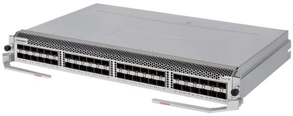
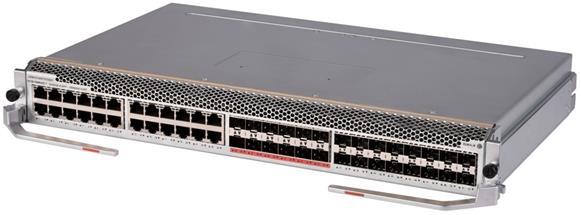
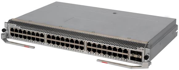
LSEM1TGS48QSSF0/LSEM3TGS48QSSF0
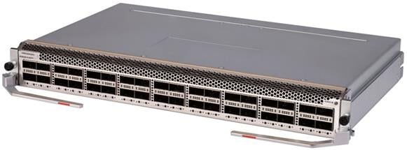
View
Figure 33 LSEM1TGS48QSSF0/LSEM3TGS48QSSF0 interface module view (LSEM1TGS48QSSF0 as an example)
Technical specifications
Table 36 LSEM1TGS48QSSF0/LSEM3TGS48QSSF0 technical specifications
|
Item |
LSEM1TGS48QSSF0 |
LSEM3TGS48QSSF0 |
|
Net weight |
4.50 kg (9.92 lb) |
4.30 kg (9.48 lb) |
|
Dimensions (H × W × D) |
51 × 423 × 270 mm (2.01 × 16.65 × 10.63 in) |
|
|
Power consumption |
· Minimum: 71 W · Typical: 82 W · Maximum: 175 W |
· Minimum: 71 W · Typical: 82 W · Maximum: 178 W |
|
Port quantity |
52 |
|
|
Port type |
· 40GBASE-R-QSFP+ fiber port · 10GBASE-R-SFP+ fiber port |
|
|
Transceiver modules supported |
· QSFP+ transceiver module · QSFP+ DAC cable · QSFP+ AOC cable · QSFP+ to SFP+ DAC cable · 10G SFP+ transceiver module · 10G SFP+ DAC cable · 1G SFP transceiver module |
|
|
Services |
Provides data access and switching with four 40GE fiber ports and forty-eight 10GE fiber ports. |
|
|
Hot swapping |
Supported |
|
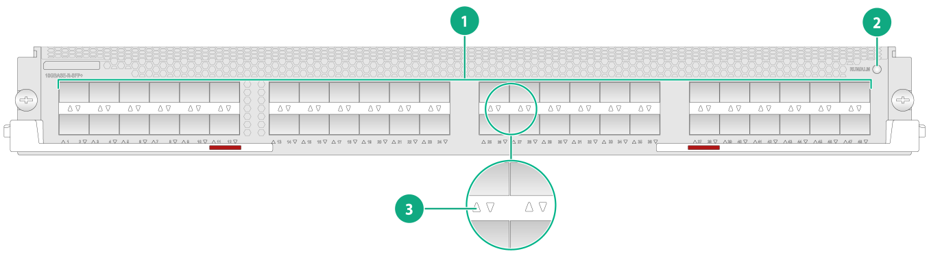
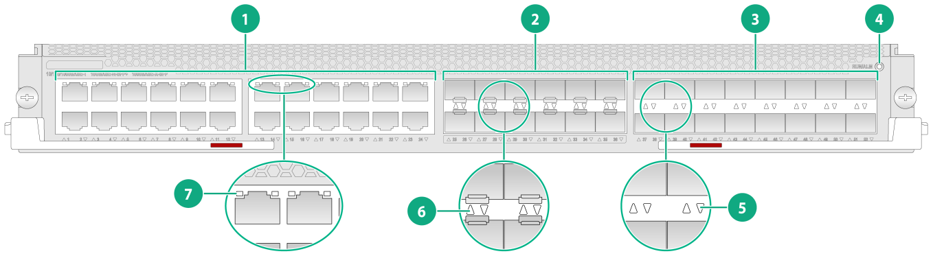
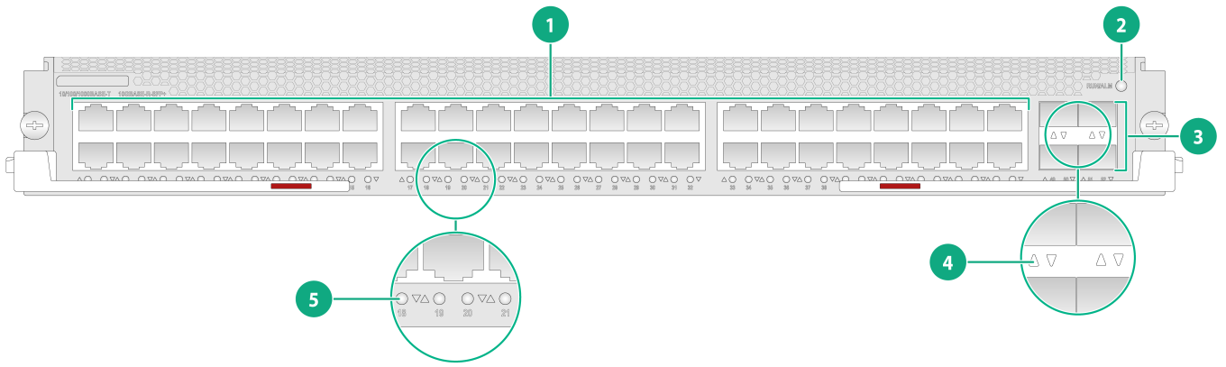
Ports and LEDs
Figure 34 LSEM1TGS48QSSF0/LSEM3TGS48QSSF0 front panel
|
(1) 10GBASE-R-SFP+ fiber ports |
(2) RUN/ALM LED |
|
(3) 40GBASE-R-QSFP+ fiber ports |
(4) 40GBASE-R-QSFP+ fiber port LEDs |
|
(5) 10GBASE-R-SFP+ fiber port LEDs |
|
Table 37 LED description
|
LED |
Status |
Description |
|
QSFP28 port LED |
Flashing |
The QSFP28 port is sending or receiving data. |
|
On |
A link is present on the QSFP28 port. |
|
|
Off |
No link is present on the QSFP28 port. |
|
|
SFP+ port LED |
Flashing |
The SFP+ port is sending or receiving data. |
|
On |
A link is present on the SFP+ port. |
|
|
Off |
No link is present on the SFP+ port. |
|
|
RUN/ALM LED |
Flashing green (once per two seconds) |
The interface module is operating correctly. |
|
Flashing green (four times per second) |
The interface module is loading software. |
|
|
Steady green |
The interface module is starting up. |
|
|
Steady red |
The interface module is faulty, or a high severity alarm has occurred on the interface module. |
|
|
Flashing red (once per four seconds) |
The temperature of the interface module has exceeded the upper warning threshold or fell below the lower warning threshold. |
|
|
Off |
The interface module is faulty or not present. |
|
|
NOTE: · You can determine whether a QSFP28 port supports 100GE downspeed to 40GE by observing the color of its LED. If the LED is yellow, the QSFP28 port supports 100GE downspeed to 40GE. If the LED is green, the QSFP28 port does not support 100GE downspeed to 40GE. · You can identify the rate of an SFP+ port by observing the color of its LED. When the LED is green, the SFP+ port is operating at 10 Gbps. When the LED is yellow, the SFP+ port is operating at 1000 Mbps. |
LSEM1TGS48SD0/LSEM2TGS48SD0
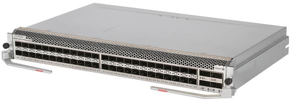
View
Figure 35 LSEM1TGS48SD0/LSEM2TGS48SD0 interface module view (LSEM1TGS48SD0 as an example)
Technical specifications
Table 38 LSEM1TGS48SD0/LSEM2TGS48SD0 technical specifications
|
Item |
LSEM1TGS48SD0 |
LSEM2TGS48SD0 |
|
Net weight |
3.50 kg (7.72 lb) |
3.60 kg (7.94 lb) |
|
Dimensions (H × W × D) |
51 × 423 × 270 mm (2.01 × 16.65 × 10.63 in) |
|
|
Power consumption |
· Minimum: 40 W · Typical: 65 W · Maximum: 93 W |
|
|
Port quantity |
48 |
|
|
Port type |
10GBASE-R-SFP+ fiber ports |
|
|
Transceiver modules supported |
· 10G SFP+ transceiver module · 10G SFP+ DAC cable · 1G SFP transceiver module |
|
|
Services |
Provides data access and switching with forty-eight 10GE fiber ports. |
|
|
Hot swapping |
Supported |
|
Ports and LEDs
Figure 36 LSEM1TGS48SD0/LSEM2TGS48SD0 front panel
|
(1) 10GBASE-R-SFP+ fiber ports |
(2) RUN/ALM LED |
|
(3) 10GBASE-R-SFP+ fiber port LEDs |
|
Table 39 LED description
|
LED |
Status |
Description |
|
SFP+ port LED |
Flashing |
The SFP+ port is sending or receiving data. |
|
On |
A link is present on the SFP+ port. |
|
|
Off |
No link is present on the SFP+ port. |
|
|
RUN/ALM LED |
Flashing green (once per two seconds) |
The interface module is operating correctly. |
|
Flashing green (four times per second) |
The interface module is loading software. |
|
|
Steady green |
The interface module is starting up. |
|
|
Steady red |
The interface module is faulty, or a high severity alarm has occurred on the interface module. |
|
|
Flashing red (once per four seconds) |
The temperature of the interface module has exceeded the upper warning threshold or fell below the lower warning threshold. |
|
|
Off |
The interface module is faulty or not present. |
|
|
NOTE: You can identify the rate of an SFP+ port by observing the color of its LED. When the LED is green, the SFP+ port is operating at 10 Gbps. When the LED is yellow, the SFP+ port is operating at 1000 Mbps. |
LSEM1TGT48SD0
View
Figure 37 LSEM1TGT48SD0 interface module view
Technical specifications
Table 40 LSEM1TGT48SD0 technical specifications
|
Item |
LSEM1TGT48SD0 |
|
Net weight |
3.70 kg (8.16 lb) |
|
Dimensions (H × W × D) |
51 × 423 × 270 mm (2.01 × 16.65 × 10.63 in) |
|
Power consumption |
· Minimum: 82 W · Typical: 125 W · Maximum: 173 W |
|
Port quantity |
48 |
|
Port type |
10G/5G/2.5G/1000/100BASE-T port |
|
Cables supported |
Category 5e/6/6A and higher twisted-pair cables |
|
Services |
Provides data access and switching with forty-eight 10G/5G/2.5G/1000/100BASE-T copper ports. |
|
Hot swapping |
Supported |
Ports and LEDs
Figure 38 LSEM1TGT48SD0 front panel
|
(1) 10G/5G/2.5G/1000/100BASE-T ports |
(2) RUN/ALM LED |
|
(3) 10G/5G/2.5G/1000/100BASE-T port LEDs |
|
Table 41 LED description
|
LED |
Status |
Description |
|
RJ-45 Ethernet port LED |
Flashing |
The port is sending or receiving data. |
|
On |
A link is present on the port. |
|
|
Off |
No link is present on the port. |
|
|
RUN/ALM LED |
Flashing green (once per two seconds) |
The interface module is operating correctly. |
|
Flashing green (four times per second) |
The interface module is loading software. |
|
|
Steady green |
The interface module is starting up. |
|
|
Steady red |
The interface module is faulty, or a high severity alarm has occurred on the interface module. |
|
|
Flashing red (once per four seconds) |
The temperature of the interface module has exceeded the upper warning threshold or fell below the lower warning threshold. |
|
|
Off |
The interface module is faulty or not present. |
|
|
NOTE: You can identify the rate of an SFP+ port by observing the color of its LED. When the LED is green, the SFP+ port is operating at 10 Gbps. When the LED is yellow, the SFP+ port is operating at 1000 Mbps. |
1G interface modules
LSEM1GT24GP16TSSD0
View
Figure 39 LSEM1GT24GP16TSSD0 interface module view
Technical specifications
Table 42 LSEM1GT24GP16TSSD0 technical specifications
|
Item |
LSEM1GT24GP16TSSD0 |
|
Net weight |
3.35 kg (7.39 lb) |
|
Dimensions (H × W × D) |
51 × 423 × 270 mm (2.01 × 16.65 × 10.63 in) |
|
Power consumption |
· Minimum: 28 W · Typical: 37 W · Maximum: 62 W |
|
Port quantity |
52 |
|
Port type |
· 10GBASE-R-SFP+ fiber port · 1000BASE-X-SFP fiber port · 10/100/1000BASE-T port |
|
Transceiver modules and cables supported |
· 10G SFP+ transceiver module · 10G SFP+ DAC cable · 100M/1G SFP transceiver module · Category 5e twisted-pair cable |
|
Services |
Provides data access and switching with twelve 10GE fiber ports, sixteen GE fiber ports, and forty-eight GE copper ports. |
|
Hot swapping |
Supported |
Ports and LEDs
Figure 40 LSEM1GT24GP16TSSD0 front panel
|
(1) 10/100/1000BASE-T ports |
(2) 10GBASE-R-SFP+ fiber ports |
|
(3) 1000BASE-X-SFP fiber ports |
(4) RUN/ALM LED |
|
(5) 1000BASE-X-SFP fiber port LEDs |
(6) 10GBASE-R-SFP+ fiber port LEDs |
|
(7) 10/100/1000BASE-T ports LEDs |
|
Table 43 LED description
|
LED |
Status |
Description |
|
SFP+ port LED |
Flashing |
The SFP+ port is sending or receiving data. |
|
On |
A link is present on the SFP+ port. |
|
|
Off |
No link is present on the SFP+ port. |
|
|
SFP port LED |
Flashing |
The SFP port is sending or receiving data. |
|
On |
A link is present on the SFP port. |
|
|
Off |
No link is present on the SFP port. |
|
|
RJ-45 Ethernet port LED |
Flashing |
The port is sending or receiving data. |
|
On |
A link is present on the port. |
|
|
Off |
No link is present on the port. |
|
|
RUN/ALM LED |
Flashing green (once per two seconds) |
The interface module is operating correctly. |
|
Flashing green (four times per second) |
The interface module is loading software. |
|
|
Steady green |
The interface module is starting up. |
|
|
Steady red |
The interface module is faulty, or a high severity alarm has occurred on the interface module. |
|
|
Flashing red (once per four seconds) |
The temperature of the interface module has exceeded the upper warning threshold or fell below the lower warning threshold. |
|
|
Off |
The interface module is faulty or not present. |
|
|
NOTE: You can identify the rate of an SFP+ port by observing the color of its LED. When the LED is green, the SFP+ port is operating at 10 Gbps. When the LED is yellow, the SFP+ port is operating at 1000 Mbps. |
LSEM1GT48TS24QSSD0
View
Figure 41 LSEM1GT48TS24QSSD0 interface module view
Technical specifications
Table 44 LSEM1GT48TS24QSSD0 technical specifications
|
Item |
LSEM1GT48TS24QSSD0 |
|
Net weight |
3.90 kg (8.60 lb) |
|
Dimensions (H × W × D) |
51 × 423 × 270 mm (2.01 × 16.65 × 10.63 in) |
|
Power consumption |
· Minimum: 52 W · Typical: 67 W · Maximum: 115 W |
|
Port quantity |
72 |
|
Port type |
· 40GBASE-R-QSFP+ fiber port · 10GBASE-R-SFP+ fiber port · 10/100/1000BASE-T port |
|
Transceiver modules supported |
· QSFP+ transceiver module · QSFP+ DAC cable · QSFP+ AOC cable · QSFP+ to SFP+ DAC cable · 10G SFP+ transceiver module · 10G SFP+ DAC cable · 1G SFP transceiver module · Category 5e twisted-pair cable |
|
Services |
Provides data access and switching with two 40GE fiber ports, twenty-four 10GE fiber ports, and forty-eight GE copper ports. |
|
Hot swapping |
Supported |
Ports and LEDs
Figure 42 LSEM1GT48TS24QSSD0 front panel
|
(1) 10GBASE-R-SFP+ fiber ports |
(2) RUN/ALM LED |
|
(3) 40GBASE-R-QSFP+ fiber ports |
(4) 40GBASE-R-QSFP+ fiber port LEDs |
|
(5) 10/100/1000BASE-T ports |
(6) 10GBASE-R-SFP+ fiber port LEDs |
|
(7) 10/100/1000BASE-T ports LEDs |
|
Table 45 LED description
|
LED |
Status |
Description |
|
QSFP28 port LED |
Flashing |
The QSFP28 port is sending or receiving data. |
|
On |
A link is present on the QSFP28 port. |
|
|
Off |
No link is present on the QSFP28 port. |
|
|
SFP+ port LED |
Flashing |
The SFP+ port is sending or receiving data. |
|
On |
A link is present on the SFP+ port. |
|
|
Off |
No link is present on the SFP+ port. |
|
|
RJ-45 Ethernet port LED |
Flashing |
The port is sending or receiving data. |
|
On |
A link is present on the port. |
|
|
Off |
No link is present on the port. |
|
|
RUN/ALM LED |
Flashing green (once per two seconds) |
The interface module is operating correctly. |
|
Flashing green (four times per second) |
The interface module is loading software. |
|
|
Steady green |
The interface module is starting up. |
|
|
Steady red |
The interface module is faulty, or a high severity alarm has occurred on the interface module. |
|
|
Flashing red (once per four seconds) |
The temperature of the interface module has exceeded the upper warning threshold or fell below the lower warning threshold. |
|
|
Off |
The interface module is faulty or not present. |
|
|
NOTE: You can identify the rate of an SFP+ port by observing the color of its LED. When the LED is green, the SFP+ port is operating at 10 Gbps. When the LED is yellow, the SFP+ port is operating at 1000 Mbps. |
LSEM1GT48TSSD0
View
Figure 43 LSEM1GT48TSSD0 interface module view
Technical specifications
Table 46 LSEM1GT48TSSD0 technical specifications
|
Item |
LSEM1GT48TSSD0 |
|
Net weight |
3.25 kg (7.16 lb) |
|
Dimensions (H × W × D) |
51 × 423 × 270 mm (2.01 × 16.65 × 10.63 in) |
|
Power consumption |
· Minimum: 28 W · Typical: 47 W · Maximum: 55 W |
|
Port quantity |
52 |
|
Port type |
· 10GBASE-R-SFP+ fiber port · 10/100/1000BASE-T port |
|
Transceiver modules supported |
· 10G SFP+ transceiver module · 10G SFP+ DAC cable · 100M/1G SFP transceiver module · Category 5e twisted-pair cable |
|
Services |
Provides data access and switching with four 10GE fiber ports and forty-eight GE copper ports. |
|
Hot swapping |
Supported |
Ports and LEDs
Figure 44 LSEM1GT48TSSD0 front panel
|
(1) 10/100/1000BASE-T ports |
(2) RUN/ALM LED |
|
(3) 10GBASE-R-SFP+ fiber ports |
(4) 10GBASE-R-SFP+ fiber port LEDs |
|
(5) 10/100/1000BASE-T ports LEDs |
|
Table 47 LED description
|
LED |
Status |
Description |
|
SFP+ port LED |
Flashing |
The SFP+ port is sending or receiving data. |
|
On |
A link is present on the SFP+ port. |
|
|
Off |
No link is present on the SFP+ port. |
|
|
RJ-45 Ethernet port LED |
Flashing |
The port is sending or receiving data. |
|
On |
A link is present on the port. |
|
|
Off |
No link is present on the port. |
|
|
RUN/ALM LED |
Flashing green (once per two seconds) |
The interface module is operating correctly. |
|
Flashing green (four times per second) |
The interface module is loading software. |
|
|
Steady green |
The interface module is starting up. |
|
|
Steady red |
The interface module is faulty, or a high severity alarm has occurred on the interface module. |
|
|
Flashing red (once per four seconds) |
The temperature of the interface module has exceeded the upper warning threshold or fell below the lower warning threshold. |
|
|
Off |
The interface module is faulty or not present. |
|
|
NOTE: You can identify the rate of an SFP+ port by observing the color of its LED. When the LED is green, the SFP+ port is operating at 10 Gbps. When the LED is yellow, the SFP+ port is operating at 1000 Mbps. |
LSEM1GV48TSSD0
View
Figure 45 LSEM1GV48TSSD0 interface module view
Technical specifications
Table 48 LSEM1GV48TSSD0 technical specifications
|
Item |
LSEM1GV48TSSD0 |
|
Net weight |
3.35 kg (7.39 lb) |
|
Dimensions (H × W × D) |
51 × 423 × 270 mm (2.01 × 16.65 × 10.63 in) |
|
Power consumption |
· Minimum: 28 W · Typical: 47 W · Maximum: 55 W |
|
Port quantity |
52 |
|
Port type |
· 10GBASE-R-SFP+ fiber port · 10/100/1000BASE-T-PoE+ port |
|
Transceiver modules supported |
· 10G SFP+ transceiver module · 10G SFP+ DAC cable · 100M/1G SFP transceiver module · Category 5e twisted-pair cable |
|
Services |
Provides data access and switching with four 10GE fiber ports and forty-eight GE copper ports. |
|
Hot swapping |
Supported |
Ports and LEDs
Figure 46 LSEM1GV48TSSD0 front panel
|
(1) 10/100/1000BASE-T-PoE+ ports |
(2) RUN/ALM LED |
|
(3) 10GBASE-R-SFP+ fiber ports |
(4) 10GBASE-R-SFP+ fiber port LEDs |
|
(5) 10/100/1000BASE-T-PoE+ port LEDs |
|
Table 49 LED description
|
LED |
Status |
Description |
|
SFP+ port LED |
Flashing |
The SFP+ port is sending or receiving data. |
|
On |
A link is present on the SFP+ port. |
|
|
Off |
No link is present on the SFP+ port. |
|
|
RJ-45 Ethernet port LED |
Flashing |
The port is sending or receiving data. |
|
On |
A link is present on the port. |
|
|
Off |
No link is present on the port. |
|
|
RUN/ALM LED |
Flashing green (once per two seconds) |
The interface module is operating correctly. |
|
Flashing green (four times per second) |
The interface module is loading software. |
|
|
Steady green |
The interface module is starting up. |
|
|
Steady red |
The interface module is faulty, or a high severity alarm has occurred on the interface module. |
|
|
Flashing red (once per four seconds) |
The temperature of the interface module has exceeded the upper warning threshold or fell below the lower warning threshold. |
|
|
Off |
The interface module is faulty or not present. |
|
|
NOTE: You can identify the rate of an SFP+ port by observing the color of its LED. When the LED is green, the SFP+ port is operating at 10 Gbps. When the LED is yellow, the SFP+ port is operating at 1000 Mbps. |
Switch fabric modules
|
|
IMPORTANT: · Do not mix the LSEM1SF06B0 and LSEM1SF06D0 switch fabric modules on the same switch. · Do not use the LSEM1SF06D0 switch fabric module and LSEM1TGS48SD0, or LSEM1TGS16GP32SD0 interface modules on the same switch. |
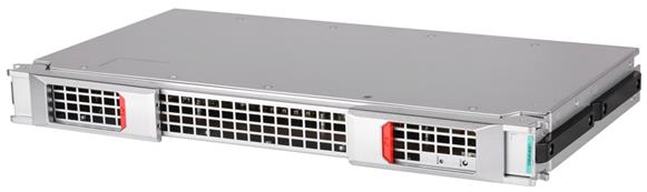
LSEM1SF06B0/LSEM1SF06D0
Front panel
Figure 47 LSEM1CGQ16SF0/LSEM1SF06D0 switch fabric module view (LSEM1CGQ16SF0 as an example)
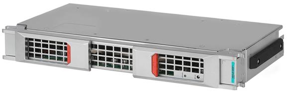
Technical specifications
Table 50 LSEM1SF06B0/LSEM1SF06D0 technical specifications
|
Item |
LSEM1SF06B0 |
LSEM1SF06D0 |
|
Net weight |
3.25 kg (7.16 lb) |
3.35 kg (7.39 lb) |
|
Dimensions (H × W × D) |
51 × 423 × 270 mm (2.01 × 16.65 × 10.63 in) |
|
|
Power consumption |
· Minimum: 19 W · Typical: 34 W · Maximum: 53 W |
· Minimum: 55 W · Typical: 63 W · Maximum: 95 W |
|
Hot swapping |
Supported |
|
|
Applicable switch models |
S10506X-G/S10506X-G-PoE |
|
Buttons and LEDs
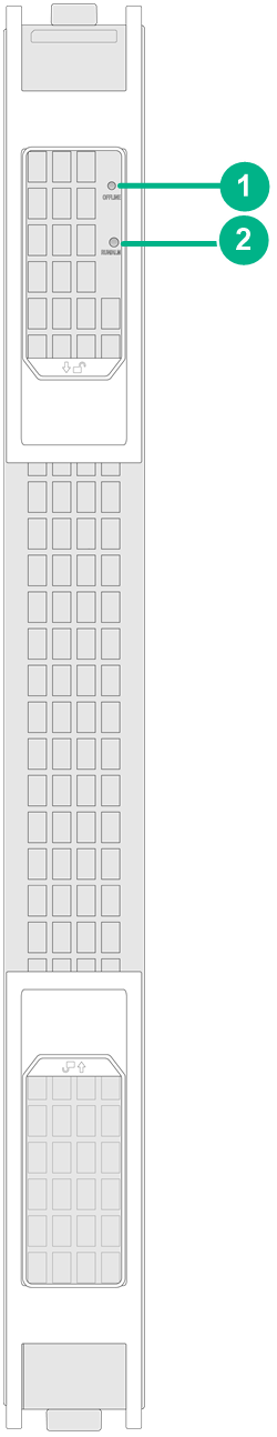
Figure 48 LSEM1SF06B0/LSEM1SF06D0 front panel
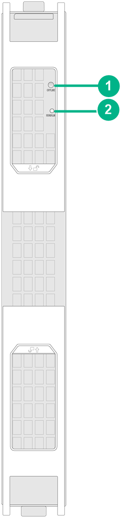
|
(1) Offline button |
(2) RUN/ALM LED |
Table 51 LED description
|
LED |
Status |
Description |
|
Status LED |
Flashing green (once per two seconds) |
The switch fabric module is operating correctly. |
|
Flashing green (four times per second) |
The switch fabric module is starting up. |
|
|
Steady green |
The switch fabric module has been isolated. |
|
|
Steady red |
The switch fabric module is faulty, or a high severity alarm has occurred on the switch fabric module. |
|
|
Flashing red (once per four seconds) |
The temperature of the switch fabric module has exceeded the upper warning temperature threshold or dropped below the lower temperature threshold. |
|
|
Off |
The switch fabric module is faulty or not present. |
Table 52 Button description
|
Button mark |
Name |
Description |
|
OFFLINE |
Offline button |
To remove the switch fabric module, press and hold the offline button for six seconds until the status LED of the module is steady yellow. |
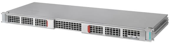
LSEM1SF08C0
View
Figure 49 LSEM1SF08C0 switch fabric module view
Technical specifications
Table 53 LSEM1SF08C0 technical specifications
|
Item |
LSEM1SF08C0 |
|
Net weight |
4.30 kg (9.48 lb) |
|
Dimensions (H × W × D) |
46 × 467 × 273 mm (1.81 × 18.39 × 10.75 in) |
|
Power consumption |
· Minimum: 61 W · Typical: 73 W · Maximum: 112 W |
|
Hot swapping |
Supported |
|
Applicable switch models |
S10508X-G |
Buttons and LEDs
Figure 50 LSEM1SF08C0 front panel
|
(1) Offline button |
(2) RUN/ALM LED |
Table 54 LED description
|
LED |
Status |
Description |
|
Status LED |
Flashing green (once per two seconds) |
The switch fabric module is operating correctly. |
|
Flashing green (four times per second) |
The switch fabric module is starting up. |
|
|
Steady green |
The switch fabric module has been isolated. |
|
|
Steady red |
The switch fabric module is faulty, or a high severity alarm has occurred on the switch fabric module. |
|
|
Flashing red (once per four seconds) |
The temperature of the switch fabric module has exceeded the upper warning temperature threshold or dropped below the lower temperature threshold. |
|
|
Off |
The switch fabric module is faulty or not present. |
Table 55 Button description
|
Button mark |
Name |
Description |
|
OFFLINE |
Offline button |
To remove the switch fabric module, press and hold the offline button for six seconds until the status LED of the module is steady yellow. |
LSEM1SF12B0
Front panel
Figure 51 LSEM1SF12B0 switch fabric module view
Technical specifications
Table 56 LSEM1SF12B0 technical specifications
|
Item |
LSEM1SF12B0 |
|
Net weight |
6.50 kg (14.33 lb) |
|
Dimensions (H × W × D) |
46 × 698 × 273 mm (1.81 × 27.48 × 10.75 in) |
|
Power consumption |
· Minimum: 62 W · Typical: 81 W · Maximum: 126 W |
|
Hot swapping |
Supported |
|
Applicable switch models |
S10512X-G |
Buttons and LEDs
Figure 52 LSEM1SF12B0 front panel
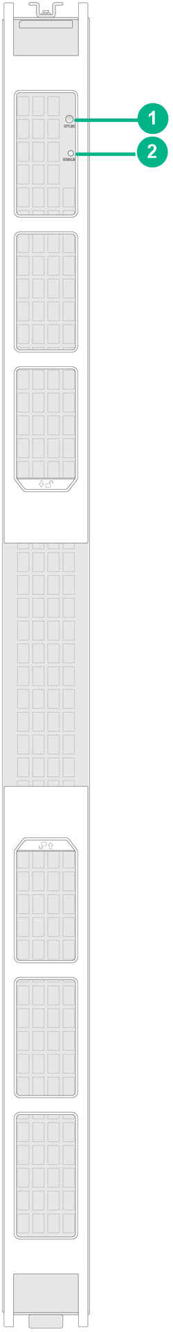
|
(1) Offline button |
(2) RUN/ALM LED |
Table 57 LED description
|
LED |
Status |
Description |
|
Status LED |
Flashing green (once per two seconds) |
The switch fabric module is operating correctly. |
|
Flashing green (four times per second) |
The switch fabric module is starting up. |
|
|
Steady green |
The switch fabric module has been isolated. |
|
|
Steady red |
The switch fabric module is faulty, or a high severity alarm has occurred on the switch fabric module. |
|
|
Flashing red (once per four seconds) |
The temperature of the switch fabric module has exceeded the upper warning temperature threshold or dropped below the lower temperature threshold. |
|
|
Off |
The switch fabric module is faulty or not present. |
Table 58 Button description
|
Button mark |
Name |
Description |
|
OFFLINE |
Offline button |
To remove the switch fabric module, press and hold the offline button for six seconds until the status LED of the module is steady yellow. |
Power supplies
The switch supports N+N (dual power inputs) or N+1 (single power input) power supply redundancy. Determine the number of power supplies based on the power supply mode and system power consumption. Make sure the maximum total output power of the installed power supplies is greater than the system power consumption. Reserve a 20% power surplus as a best practice.
|
|
IMPORTANT: When the temperature of a power supply exceeds the upper limit or drops below the lower limit, the power supply shuts down automatically. When the temperature falls into the normal range, the power supply starts up automatically. |
PSR1600B-12A-B
View
Figure 53 PSR1600B-12A-B power supply view
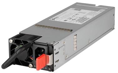
Technical specifications
Table 59 PSR1600B-12A-B technical specifications
|
Item |
Specification |
|
Net weight |
1.10 kg (2.43 lb) |
|
Dimensions (H × W × D) |
40 × 74 × 225 mm (1.57 × 2.91 × 8.86 in) |
|
Rated input voltage range |
· 100 to 240 VAC @ 50 or 60 Hz, 10 A · 240 VDC @ 8 A |
|
Maximum input current |
10.5 A |
|
Rated output voltage range |
12.0 V |
|
Maximum output current |
131 A (12 V) |
|
Maximum output power |
· 786 W @ 110 VAC · 1572 W @ 220 VAC · 1572 W @ 240 VDC |
|
Heat dissipation |
Equipped with fans, rear-to-front airflow (from the golden plating to the front panel) |
|
Hot swapping |
Supported |
|
Operating temperature |
–10°C to +55°C (14°F to 131°F) |
|
Storage temperature |
–40°C to +70°C (–40°F to +158°F) |
|
Applicable switch models |
All S10500X-G switch models |
LEDs
Figure 54 PSR1600B-12A-B front panel
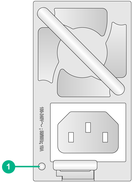
|
(1) Status LED |
Table 60 LED description
|
LED |
Status |
Description |
|
Status LED |
Steady green |
The power supply is operating correctly. |
|
Flashing green (once per two seconds) |
The power supply has correct power input and is in standby state with 12 V standby output and without 12 V main output. |
|
|
Flashing green (twice per second) |
The power supply is updating software. |
|
|
Flashing green (once per three seconds) |
The power supply has entered cold redundancy state. |
|
|
Steady yellow |
The power supply is faulty. |
|
|
Flashing yellow (once per second) |
· The power supply is operating correctly, but an alarm has occurred (such as input undervoltage, output overcurrent, and overtemperature). · The power supply does not have power input, but the backup power supplies have correct power input. |
|
|
Off |
No power input. |
PSR1600-54A-B
View
Figure 55 PSR1600-54A-B power supply view
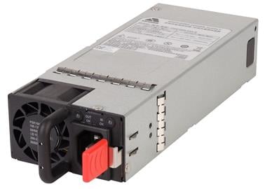
Technical specifications
Table 61 PSR1600-54A-B technical specifications
|
Item |
Specification |
|
Net weight |
0.95 kg (2.10 lb) |
|
Dimensions (H × W × D) |
40 × 74 × 185 mm (1.57 × 2.91 × 7.28 in) |
|
Rated input voltage |
· 100 to 130 VAC @ 50 or 60 Hz, 10 to 12 A · 200 to 240 VAC @ 50 or 60 Hz, 8 to 10 A · 240 VDC @ 8 A |
|
Maximum output current |
· AC input: 13 A · HVDC input: 10 A |
|
Rated output voltage |
55.5 V |
|
Maximum output current |
29 A |
|
Maximum output power |
· 950 W @ 110 VAC · 1600 W @ 220 VAC · 1600 W @ 240 VDC |
|
Heat dissipation |
Equipped with fans, airflow from the power input side to the power output side |
|
Hot swapping |
Supported |
|
Operating temperature |
–10°C to +55°C (14°F to 131°F) |
|
Storage temperature |
–40°C to +70°C (–40°F to +158°F) |
|
Applicable switch models |
S10506X-G-PoE |
LEDs
Figure 56 PSR1600-54A-B front panel
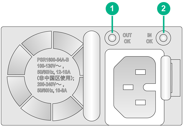
|
(1) Output status LED (OUT OK) |
(2) Input status LED (IN OK) |
Table 62 LED description
|
LED |
Status |
Description |
|
OUT OK |
Steady green |
Normal power output. |
|
Flashing green |
Normal power input, and 12 V output disabled. |
|
|
Steady red |
The power supply has entered protection state (no power output). |
|
|
Alternating between red and green (once per second) |
Abnormal power input and output. |
|
|
Off |
No power output. |
|
|
IN OK |
Steady green |
Normal power input. |
|
Steady red |
Abnormal power input. |
|
|
Off |
No power input. |
PSR2000-12D-B
View
Figure 57 PSR2000-12D-B power supply view

Technical specifications
Table 63 PSR2000-12D-B technical specifications
|
Item |
PSR2000-12D-B |
|
Net weight |
1.10 kg (2.43 lb) |
|
Dimensions (H × W × D) |
40 × 74 × 225 mm (1.57 × 2.91 × 8.86 in) |
|
Rated input voltage |
–48 to –60 VDC @ 60 A |
|
Maximum input current |
60 A |
|
Rated output voltage |
12.0 V |
|
Maximum output current |
167 A |
|
Maximum output power |
2000 W |
|
Heat dissipation |
Euipped with fans, rear-to-front airflow (from the golden plating to the front panel) |
|
Hot swapping |
Supported |
|
Operating temperature |
–10°C to +55°C (14°F to 131°F) |
|
Storage temperature |
–40°C to +70°C (–40°F to +158°F) |
|
Applicable switch models |
All S10500X-G switch models |
LEDs
Figure 58 PSR2000-12D-B front panel
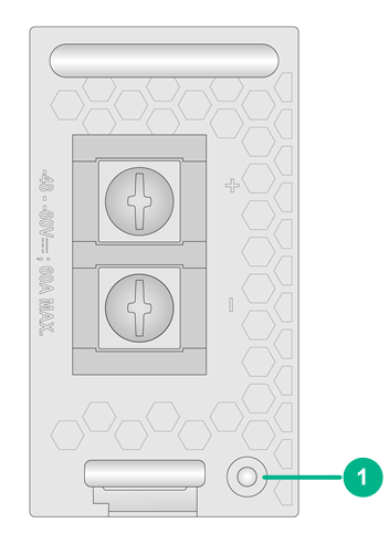
|
(1) Status LED |
Table 64 LED description
|
LED |
Status |
Description |
|
Status LED |
Steady green |
The power supply is operating correctly. |
|
Flashing green (once per second) |
The power supply is updating software. |
|
|
Flashing green (once per two seconds) |
The power supply has correct power input and is in standby state with 12 V standby output and without 12 V main output. |
|
|
Steady red |
The power supply is faulty. |
|
|
Flashing yellow (once per second) |
The power supply does not have power input, but the backup power supplies have correct power input. |
|
|
Flashing yellow (twice per second) |
The power supply is operating correctly, but an alarm has occurred (such as input undervoltage, output overcurrent, and overtemperature). |
|
|
Off |
No power input. |
Fan trays
FAN-80B-4-A
View
Figure 59 FAN-80B-4-A fan tray view
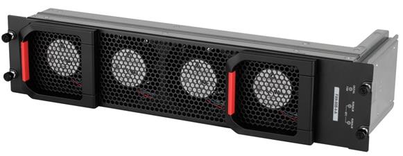
Technical specifications
Table 65 FAN-80B-4-A technical specifications
|
Item |
FAN-80B-4-A |
|
Net weight |
2.75 kg (6.06 lb) |
|
Dimensions (H × W × D) |
93 × 432 × 143 mm (3.66 × 17.01 × 5.63 in) |
|
Power consumption |
· Minimum: 30 W · Typical: 100 W · Maximum: 230 W |
|
Number of fans |
4 |
|
Fan diameter |
80 mm (3.15 in) |
|
Maximum air flow rate |
420 CFM |
|
Airflow direction |
Air exhausted from the faceplate |
|
Hot swapping |
Supported |
|
Auto speed adjustment |
Supported |
|
Alarm detection |
Supported |
|
Applicable switch models |
S10506X-G/S10506X-G-PoE |
LEDs
Figure 60 FAN-80B-4-A front panel
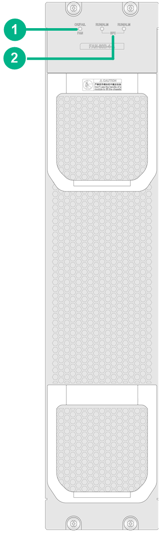
|
(1) Fan tray status LED (FAN) |
(2) Switch fabric module status LED (SFC) |
Table 66 LED description
|
LED |
Status |
Description |
|
Fan tray status LED (FAN) |
Steady green |
The fan tray is operating correctly. |
|
Steady red |
The fan tray is faulty. |
|
|
Off |
The fan tray has not been powered on. |
|
|
Switch fabric module status LED (SFC) |
Flashing green (once per two seconds) |
The switch fabric module is operating correctly. |
|
Flashing green (four times per second) |
The switch fabric module is starting up. |
|
|
Steady green |
The switch fabric module has been isolated. |
|
|
Steady red |
A high severity alarm has occurred on the switch fabric module or the switch fabric module is faulty. |
|
|
Flashing red (once per four seconds) |
The switch fabric module temperature has exceeded the upper warning threshold or fell below the lower warning threshold. |
|
|
Off |
The switch fabric module is not present or is faulty. |
FAN-80B-5-A
View
Figure 61 FAN-80B-5-A fan tray view
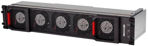
Technical specifications
Table 67 FAN-80B-5-A technical specifications
|
Item |
FAN-80B-5-A |
|
|
Net weight |
3.85 kg (8.49 lb) |
|
|
Dimensions (H × W × D) |
93 × 527 × 162 mm (3.66 × 20.75 × 6.38 in) |
|
|
Power consumption |
· Minimum: 34 W · Typical: 107 W · Maximum: 276 W |
|
|
Number of fans |
5 |
|
|
Fan diameter |
80 mm (3.15 in) |
|
|
Maximum air flow rate |
525 CFM |
|
|
Airflow direction |
Air exhausted from the faceplate |
|
|
Hot swapping |
Supported |
|
|
Auto speed adjustment |
Supported |
|
|
Alarm detection |
Supported |
|
|
Applicable switch models |
S10508X-G |
|
LEDs
Figure 62 FAN-80B-5-A front panel
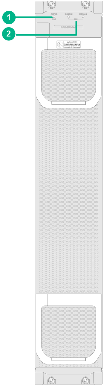
|
(1) Fan tray status LED (FAN) |
(2) Switch fabric module LED (SFC) |
Table 68 FAN-80B-5-A LED description
|
LED |
Status |
Description |
|
Fan tray status LED (FAN) |
Steady green |
The fan tray is operating correctly. |
|
Steady red |
The fan tray is faulty. |
|
|
Off |
The fan tray has not been powered on. |
|
|
Switch fabric module LED (SFC) |
Flashing green (once per two seconds) |
The switch fabric module is operating correctly. |
|
Flashing green (four times per second) |
The switch fabric module is starting up. |
|
|
Steady green |
The switch fabric module has been isolated. |
|
|
Steady red |
A high severity alarm has occurred on the switch fabric module or the switch fabric module is faulty. |
|
|
Flashing red (once per four seconds) |
The switch fabric module temperature has exceeded the upper warning threshold or fell below the lower warning threshold. |
|
|
Off |
The switch fabric module is not present or is faulty. |
FAN-80B-8-A
View
Figure 63 FAN-80B-8-A fan tray view
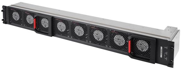
Technical specifications
Table 69 FAN-80B-8-A technical specifications
|
Item |
FAN-80B-8-A |
|
|
Net weight |
5.25 kg (11.57 lb) |
|
|
Dimensions (H × W × D) |
93 × 788 × 162 mm (3.66 × 31.02 × 6.38 in) |
|
|
Power consumption |
· Minimum: 53 W · Typical: 176 W · Maximum: 425 W |
|
|
Number of fans |
8 |
|
|
Fan diameter |
80 mm (3.15 in) |
|
|
Maximum air flow rate |
840 CFM |
|
|
Airflow direction |
Air exhausted from the faceplate |
|
|
Hot swapping |
Supported |
|
|
Auto speed adjustment |
Supported |
|
|
Alarm detection |
Supported |
|
|
Applicable switch models |
S10512X-G |
|
LEDs
Figure 64 FAN-80B-8-A front panel
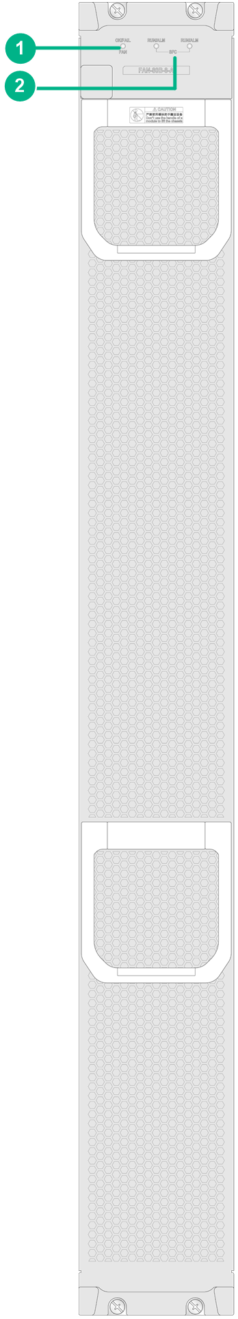
|
(1) Fan tray status LED (FAN) |
(2) Switch fabric module LED (SFC) |
Table 70 LED description
|
LED |
Status |
Description |
|
Fan tray status LED (FAN) |
Steady green |
The fan tray is operating correctly. |
|
Steady red |
The fan tray is faulty. |
|
|
Off |
The fan tray has not been powered on. |
|
|
Switch fabric module LED (SFC) |
Flashing green (once per two seconds) |
The switch fabric module is operating correctly. |
|
Flashing green (four times per second) |
The switch fabric module is starting up. |
|
|
Steady green |
The switch fabric module has been isolated. |
|
|
Steady red |
A high severity alarm has occurred on the switch fabric module or the switch fabric module is faulty. |
|
|
Flashing red (once per four seconds) |
The switch fabric module temperature has exceeded the upper warning threshold or fell below the lower warning threshold. |
|
|
Off |
The switch fabric module is not present or is faulty. |
Cables
This chapter describes cables used for connecting network ports.
Table 71 Cable description
|
Cable |
Port type |
Application |
|
RJ-45 Ethernet port at one end and DB-9 port at the other end |
Connects the console port of the switch to the console terminal. |
|
|
N/A |
Connects a DC power supply to an external DC power supply system |
|
|
N/A |
Connects an AC power supply to an external AC power supply system |
|
|
RJ-45 Ethernet ports |
Connects RJ-45 Ethernet ports to transmit data. |
|
|
SFP/SFP+ ports |
Connects the fiber ports to transmit data. |
|
|
SFP+ ports |
Connects SFP+ ports to transmit data. |
|
|
SFP28 ports |
Connects SFP28 ports to transmit data. |
|
|
SFP28 ports |
Connects SFP28 ports to transmit data. |
|
|
QSFP+ ports |
Connects QSFP+ ports to transmit data. |
|
|
QSFP+ ports |
Connects QSFP+ ports to transmit data. |
|
|
QSFP28 ports |
Connects QSFP28 ports to transmit data. |
|
|
QSFP28 ports |
Connects QSFP28 ports to transmit data. |
|
|
QSFP+ port at one end and SFP+ ports at the other end |
Connects the QSFP+ port and SFP+ ports to transmit data. |
|
|
QSFP28 port at one end and SFP28 ports at the other end |
Connects the QSFP28 port and SFP28 ports to transmit data. |
|
|
QSFP-DD ports |
Connects QSFP-DD ports to transmit data. |
Console cable
A console cable is an 8-core shielded cable, with a crimped RJ-45 connector at one end for connecting to the console port of the switch, and a DB-9 female connector at the other end for connecting to the serial port on the console terminal.
Figure 65 Console cable
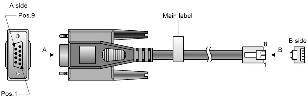
Table 72 Connection between the console ports on the switch and console ports on a PC (terminal)
|
RJ-45 |
Signal |
DB-9 |
Signal |
|
1 |
RTS |
8 |
CTS |
|
2 |
DTR |
6 |
DSR |
|
3 |
TXD |
2 |
RXD |
|
4 |
SG |
5 |
SG |
|
5 |
SG |
5 |
SG |
|
6 |
RXD |
3 |
TXD |
|
7 |
DSR |
4 |
DTR |
|
8 |
CTS |
7 |
RTS |
DC power cord
A DC power cord connects a DC power supply to an external DC power source.
Table 73 DC power cords available for the power supplies
|
DC power supply |
DC power cord length |
|
PSR2000-12D-B |
3 m (9.84 ft) |
|
15 m (49.21 ft) |
AC power cord
An AC power cords is used for connecting an AC power supply on the switch to the external AC power supply system. Select an AC power cord with a current-carrying capacity that meets the power supply requirement.
For a PSR1600B-12A-B power supply, use an IEC 60320 standard-compliant power cord that has a C13 connector (connected to the power supply). For a PSR1600-54A-B power supply, use an IEC 60320 standard-compliant power cord that has a C15 connector (connected to the power supply).
The type of the connector (connected to the power source) varies by country or region. Select a compliant connector type as needed. For the connector types of different countries or regions and the power cord codes, see H3C Power Cords & Cables User Guide.
Ethernet twisted pair cable
An Ethernet twisted pair cable consists of four pairs of insulated wires twisted together. It mainly transmits analog signals and is advantageous in transmitting data over shorter distances. The maximum transmission distance is 100 m (328.08 ft). To increase the transmission distance, you can install a maximum of four repeaters between two Ethernet twisted pair cables. With four repeaters installed, the maximum transmission distance can reach 500 m (1640.42 ft).
RJ-45 connector
An Ethernet twisted pair cable connects network devices through the RJ-45 connectors at the two ends. Figure 2 shows the pinouts of an RJ-45 connector.
Figure 66 RJ-45 connector pinout diagram
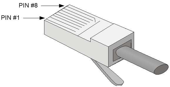
Cable pinouts
EIA/TIA cabling specifications define two standards: 568A and 568B for cable pinouts.
· Standard 568A—pin 1: white/green stripe, pin 2: green solid, pin 3: white/orange stripe, pin 4: blue solid, pin 5: white/blue stripe, pin 6: orange solid, pin 7: white/brown stripe, pin 8: brown solid.
· Standard 568B—pin 1: white/orange stripe, pin 2: orange solid, pin 3: white/green stripe, pin 4: blue solid, pin 5: white/blue stripe, pin 6: green solid, pin 7: white/brown stripe, pin 8: brown solid.
Cable type
Based on performance
Table 74 Ethernet cable description
|
Type |
Description |
|
Category 5 |
Transmits data at a maximum speed of 100 Mbps, with a bandwidth of 100 MHz. The maximum transmission distance is 100 m (328.08 ft). |
|
Category 5e |
Transmits data at a maximum speed of 1000 Mbps, with a bandwidth of 100 MHz. The maximum transmission distance is 100 m (328.08 ft). |
|
Category 6 |
Transmits data at a speed higher than 1 Gbps, with a bandwidth of 250 MHz. The maximum transmission distance is 55 m (180.45 ft) for a Category 6 unshielded twisted pair cable and 100 m (328.08 ft) for Category 6 shielded twisted pair cable. |
|
Category 6A |
Transmits data at a speed higher than 10 Gbps, with a bandwidth of 500 MHz. The maximum transmission distance is 100 m (328.08 ft). |
|
Category 7 |
Transmits data at a speed higher than 10 Gbps, with a bandwidth of 600 MHz. The maximum transmission distance is 100 m (328.08 ft). |
Based on pinouts
Ethernet twisted pair cables can be classified into straight through and crossover cables based on their pinouts.
· Straight-through—The pinouts at both ends comply with standard 568B, as shown in Figure 3.
· Crossover—The pinouts at one end comply with standard 568B, and those at the other end comply with standard 568A, as shown in Figure 4.
Figure 67 Straight-through cable

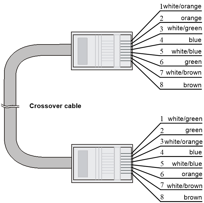
Pin assignments
Select an Ethernet twisted pair cable according to the RJ-45 Ethernet interface type on your device. An RJ-45 Ethernet interface can be MDI (for routers and PCs) or MDIX (for switches). For the pinouts of RJ-45 Ethernet interfaces, see Table 4 and Table 5.
Table 75 RJ-45 MDI interface pinouts
|
10BASE-T/100BASE-TX |
1000BASE-T |
|||
|
Signal |
Function |
Signal |
Function |
|
|
1 |
Tx+ |
Send data |
BIDA+ |
Bi-directional data cable A+ |
|
2 |
Tx- |
Send data |
BIDA- |
Bi-directional data cable A- |
|
3 |
Rx+ |
Receive data |
BIDB+ |
Bi-directional data cable B+ |
|
4 |
Reserved |
N/A |
BIDC+ |
Bi-directional data cable C+ |
|
5 |
Reserved |
N/A |
BIDC- |
Bi-directional data cable C- |
|
6 |
Rx- |
Receive data |
BIDB- |
Bi-directional data cable B- |
|
7 |
Reserved |
N/A |
BIDD+ |
Bi-directional data cable D+ |
|
8 |
Reserved |
N/A |
BIDD- |
Bi-directional data cable D- |
Table 76 RJ-45 MDI-X interface pinouts
|
Pin |
10BASE-T/100BASE-TX |
1000BASE-T |
||
|
Signal |
Function |
Signal |
Function |
|
|
1 |
Rx+ |
Receive data |
BIDB+ |
Bi-directional data cable B+ |
|
2 |
Rx- |
Receive data |
BIDB- |
Bi-directional data cable B- |
|
3 |
Tx+ |
Send data |
BIDA+ |
Bi-directional data cable A+ |
|
4 |
Reserved |
N/A |
BIDD+ |
Bi-directional data cable D+ |
|
5 |
Reserved |
N/A |
BIDD- |
Bi-directional data cable D- |
|
6 |
Tx- |
Send data |
BIDA- |
Bi-directional data cable A- |
|
7 |
Reserved |
N/A |
BIDC+ |
Bi-directional data cable C+ |
|
8 |
Reserved |
N/A |
BIDC- |
Bi-directional data cable C- |
To ensure normal communication, the pins for sending data on one port should correspond to the pins for receiving data on the peer port. When both of the ports on the two devices are MDI or MDIX, a crossover Ethernet cable is needed. A cross-over cable connects devices of the same type. When one port is MDI and the other is MDIX, a straight-through Ethernet cable is needed. A straight-through cable connects devices of different types.
An RJ-45 Ethernet interface with MDI/MDIX autosensing enabled can automatically negotiate pin roles. The S10500X-G RJ-45 Ethernet interfaces support MDI/MDIX. By default, MDI/MDIX is enabled on a port.
Making an Ethernet twisted pair cable
1. Cut the cable to length with the crimping pliers.
2. Strip off an appropriate length of the cable sheath. The length is typically that of the RJ-45 connector.
3. Untwist the pairs so that they can lie flat, and arrange the colored wires based on the wiring specifications.
4. Cut the top of the wires even with one another. Insert the wires into the RJ-45 end and make sure the wires extend to the front of the RJ-45 end and make good contact with the metal contacts in the RJ-45 end and in the correct order.
5. Crimp the RJ-45 connector with the crimping pliers until you hear a click.
6. Repeat the above steps with the other end of the cable.
7. Use a cable tester to verify the connectivity of the cable.
Optical fiber
|
|
CAUTION: Use the same types of transceiver modules, pigtail cords, patch cords, and fiber cables. If you use single-mode optical fibers, the transceiver modules, pigtail cords, patch cords, and fiber cables must be single-mode. |
Optical fiber
Optical fibers are widely used in fiber-optic communications, which are advantageous for long-distance communications.
Optical fibers can be classified into the following types:
· Single mode fiber—It has a core size of 10 µm or smaller, and has a lower modal dispersion. It carries only a single ray of light. It is mostly used for communication over longer distances.
· Multi-mode fiber—It has a core size of 50 µm or 62.5 µm or higher, and has a higher modal dispersion than single-mode optical fiber. It is mostly used for communication over shorter distances.
Table 77 Allowed maximum tensile force and crush load
|
Period of force |
Tensile load (N) |
Crush load (N/mm) |
|
Short period |
150 |
500 |
|
Long term |
80 |
100 |
Optical fiber cable
An optical fiber cable is a cable containing one or more optical fibers. The optical fiber elements are typically individually coated with plastic layers and contained in a protective tube. Optical fiber cables fall into single-mode and multi-mode.
Patch cord
A fiber that has connectors at both ends is called a patch cord. A patch cord connects one optical device to another for signal routing. Patch cords fall into single-mode and multi-mode patch cords.
· Single-mode patch cord—The jacket is yellow. It permits transmission over longer distances.
· Multi-mode patch cord—The jacket is orange. It permits transmission over shorter distances.
Patch cords are classified into SC, LC, FC, and so on based on interface type. The length of a patch cord can be 0.5 m (1.64 ft), 1 m (3.28 ft), 2 m (6.56 ft), 3 m (9.84 ft), 5 m (16.40 ft), 10 m (32.81 ft), and so on.
Pigtail cord
A pigtail cord is an optical fiber that has an optical connector on one end and a length of exposed fiber on the other. The end of the pigtail is fusion spliced to a fiber, connecting the fiber cable and transceiver.
Pigtail cords fall into single-mode (yellow) and multi-mode (orange), and can also be classified into SC, LC, FC, and so on based on interface type.
Fiber connector
Figure 69 MPO connector
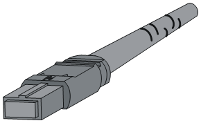
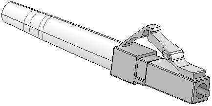
Precautions
· Make sure the fiber connector and fiber type match the transceiver module type.
· The fiber ports on the switch are provided with dust plugs. Insert the dust plugs into the fiber ports that you are not to use, to prevent particles from entering the ports.
· Fiber connectors must be protected under safe and reliable outer packing, and be fitted with dust caps. Fiber connectors must be installed with dust caps when they are not in use. Take care not to scratch their end face. Replace the dust cap if it is loose or polluted.
· Before connecting a fiber, use dust free paper and absolute alcohol to clean the end face of the fiber connector. You can brush the end face only in one direction. You also need to brush the end face of the fiber port.
· If the fiber has to pass through a metallic board hole, the hole must have a sleek and fully filleted surface (the filleting radius must be not less than 2 mm). When passing through a metallic board hole or bending along the acute side of mechanical parts, the fiber must wear jackets or cushions.
· Insert and remove a plug with care. Never exert a fierce force to the fiber or plug; otherwise the plug might be damaged or the fiber might be broken. Never pull, press or extrude the fiber fiercely. For the allowed maximum tensile load and crush load, see Table 6.
SFP+ DAC cable
You can use SFP+ DAC cables to connect SFP+ ports.
The SFP+ DAC cables available for the switch series are 10G SFP+ Cu cables, as shown in Figure 7.

|
(1) Connector |
(2) Pull latch |
SFP28 DAC cable
You can use an SFP28 DAC cable to connect SFP28 ports.
Figure 72 SFP28 DAC cable
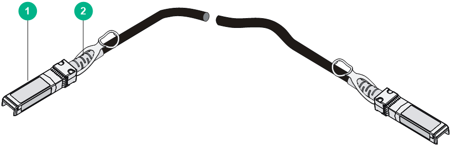
|
(1) Connector |
(2) Pull latch |
SFP28 AOC cable
You can use an SFP28 AOC cable to connect SFP28 ports.
Figure 73 SFP28 AOC cable
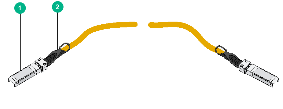
|
(1) Connector |
(2) Pull latch |
QSFP+ DAC cable
You can use a QSFP+ DAC cable to connect QSFP+ ports.
Figure 74 QSFP+ DAC cable
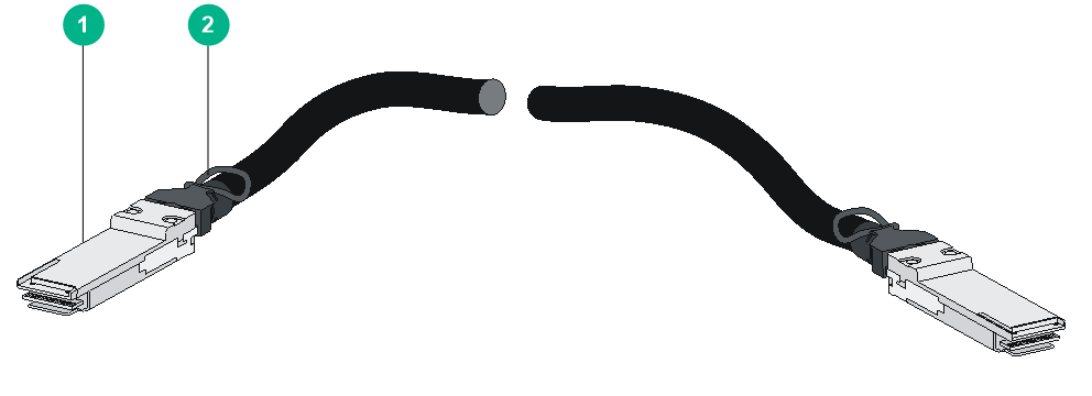
|
(1) Connector |
(2) Pull latch |
QSFP+ AOC cable
You can use a QSFP+ AOC cable to connect QSFP+ ports
Figure 75 QSFP+ AOC cable
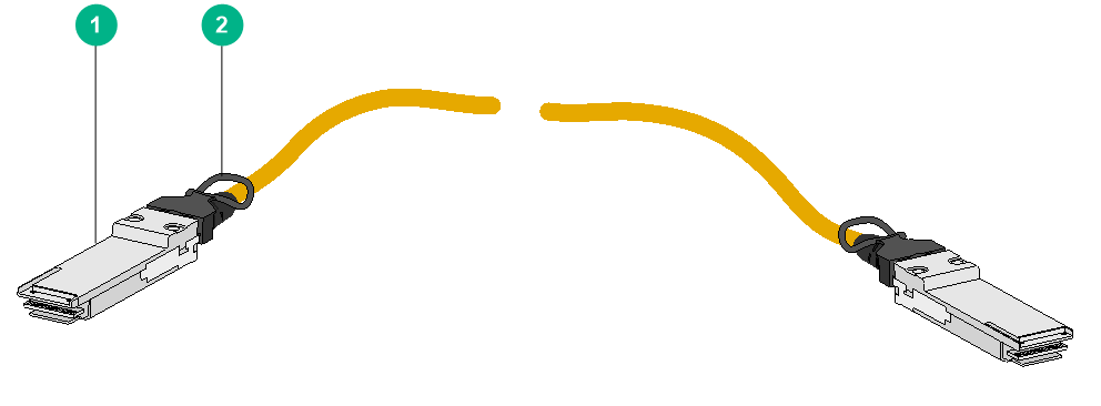
|
(1) Connector |
(2) Pull latch |
QSFP28 DAC cable
You can use a QSFP28 DAC cable to connect QSFP28 ports.
Figure 76 QSFP28 DAC cable
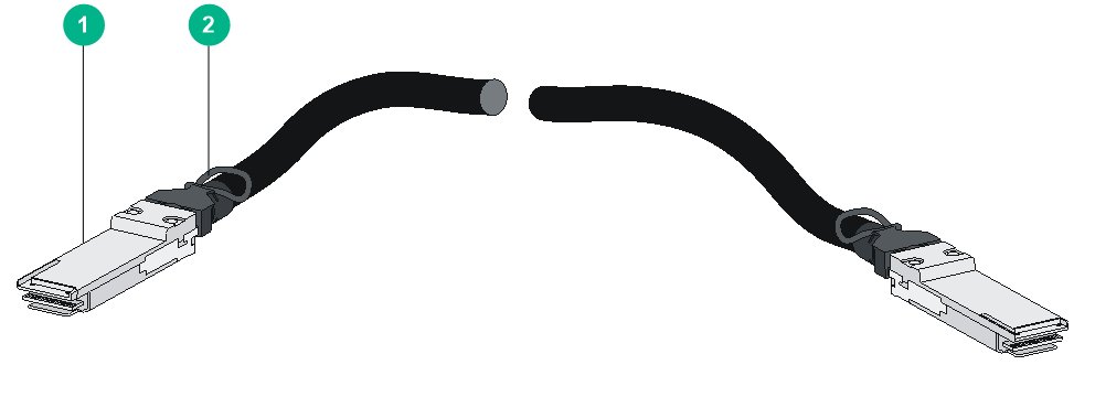
|
(1) Connector |
(2) Pull latch |
QSFP28 AOC cable
You can use a QSFP28 AOC cable to connect QSFP28 AOC ports.
Figure 77 QSFP28 AOC cable
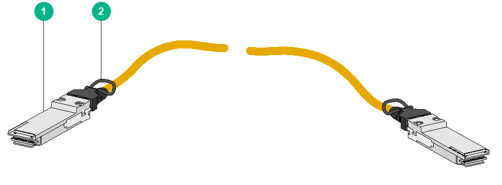
|
(1) Connector |
(2) Pull latch |
QSFP+ to SFP+ DAC cable
You can use a QSFP+ to SFP+ DAC cable to connect a QSFP+ port at one end and four SFP+ ports at the other end.
Figure 78 QSFP+ to SFP+ DAC cable
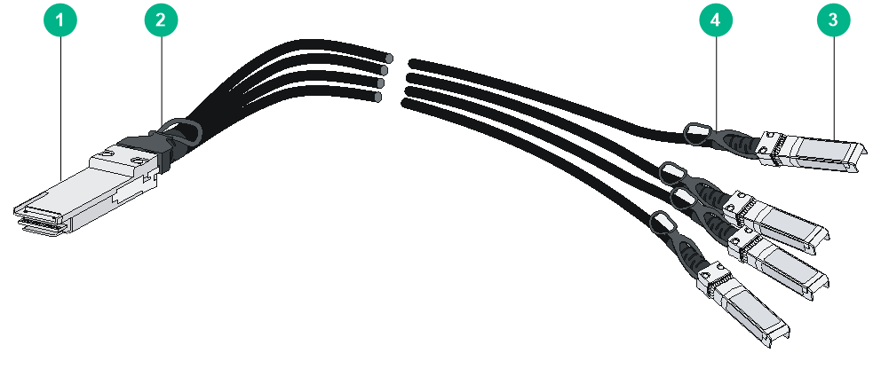
|
(1) QSFP+ connector |
(2) QSFP+ connector pull latch |
|
(3) SFP+ connector |
(4) SFP+ connector pull latch |
QSFP28 to SFP28 DAC cable
You can use a QSFP28 to SFP28 DAC cable to connect a QSFP28 port at one end and four SFP28 ports at the other end.
Figure 79 QSFP28 to SFP28 DAC cable

|
(1) QSFP28 connector |
(2) QSFP28 connector pull latch |
|
(3) SFP28 connector |
(4) SFP28 connector pull latch |
QSFP-DD copper cable
You can use a QSFP-DD copper cable to connect QSFP-DD ports.
Figure 80 QSFP-DD copper cable