- Table of Contents
- Related Documents
-
| Title | Size | Download |
|---|---|---|
| 01-Text | 4.32 MB |
Component views and descriptions
Power supply and router compatibility matrix
4 Slot arrangement and interface numbering
1 About the routers
Chassis views
The chassis views in the figures are for illustration only.
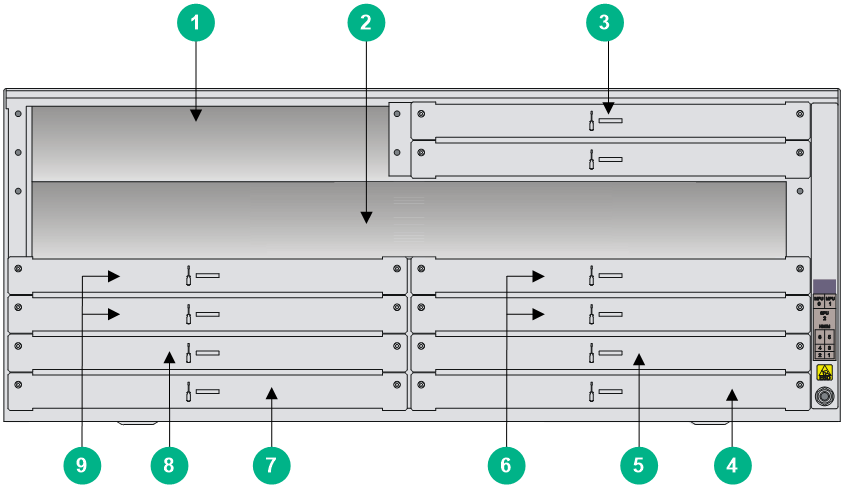
MSR5620
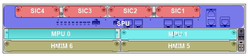
Figure1-1 Front panel

|
(1) SIC slot 4 |
(2) SIC slot 3 |
(3) USB slot 0 |
|
(4) USB slot 1 |
(5) SFP+ port 3 (SPF+3) |
(6) SFP+ port 4 (SPF+4) |
|
(7) SIC slot 2 |
(8) SIC slot 1 |
(9) Ethernet fiber port SFP0 |
|
(10) Ethernet fiber port SFP1 |
(11) Ethernet fiber port SFP2 |
(12) Ethernet copper port GE1 |
|
(13) Ethernet copper port GE2 |
(14) Ethernet copper port GE0 |
(15) MPU slot 1 |
|
(16) HMIM slot 5 |
(17) MPU slot 0 |
(18) HMIM slot 6 |
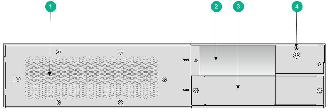
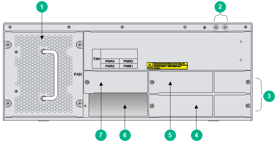
Figure1-2 Rear panel
|
(1) Fan tray |
(2) Power supply slot PWR2 |
|
(3) Power supply slot PWR1 |
(4) Grounding terminal |
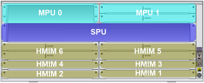
MSR 56-60
|
(1) MPU slot 0 |
(2) SPU slot |
(3) MPU slot 1 |
|
(4) HMIM slot 1 |
(5) HMIM slot 3 |
(6) HMIM slot 5 |
|
(7) HMIM slot 2 |
(8) HMIM slot 4 |
(9) HMIM slot 6 |
|
(1) Fan tray |
(2) Grounding terminal |
|
(3) Filler modules of the PoE power supply slots |
(4) Power supply slot PWR1 |
|
(5) Power supply slot PWR3 |
(6) Power supply slot PWR2 |
|
(7) Power supply slot PWR4 |
|
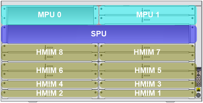
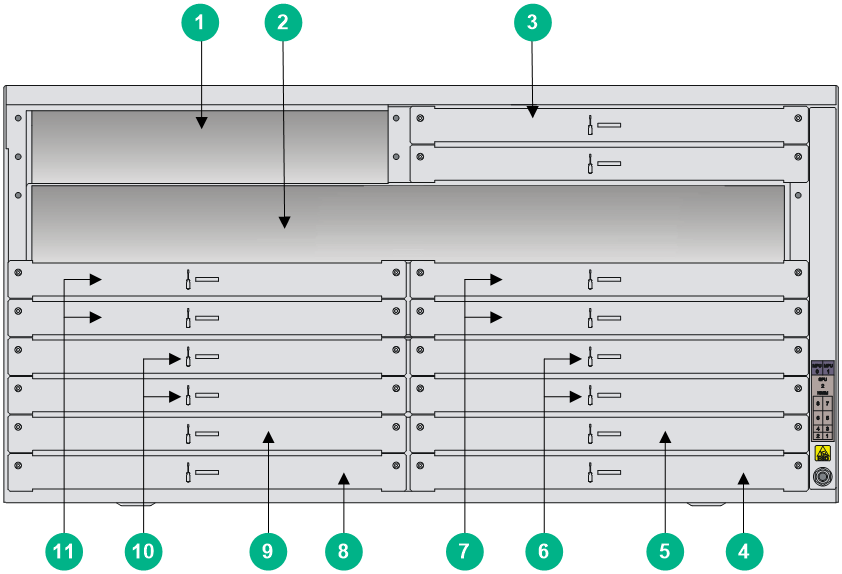
MSR 56-80
Figure1-5 Front panel
|
(1) MPU slot 0 |
(2) SPU slot |
(3) MPU slot 1 |
|
(4) HMIM slot 1 |
(5) HMIM slot 3 |
(6) HMIM slot 5 |
|
(7) HMIM slot 7 |
(8) HMIM slot 2 |
(9) HMIM slot 4 |
|
(10) HMIM slot 6 |
(11) HMIM slot 8 |
|
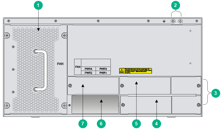
Figure1-6 Rear panel
|
(1) Fan tray |
(2) Grounding terminal |
|
|
(3) Filler modules of the PoE power supply slots |
(4) Power supply slot PWR1 |
|
|
(5) Power supply slot PWR3 |
(6) Power supply slot PWR2 |
|
|
(7) Power supply slot PWR4 |
|
|
Technical specifications
Router specifications
Table1-1 Router specifications
|
Item |
MSR5620 |
MSR 56-60 |
MSR 56-80 |
|
MPU slot |
2 |
2 |
2 |
|
SPU slot |
N/A |
1 |
1 |
|
HMIM slot |
2 |
6 |
8 |
|
Maximum power capacity |
· Single power supply: 300 W · Multiple power supplies: 450 W |
· Single power supply: 300 W · Multiple power supplies: 450 W |
· Single power supply: 300 W · Multiple power supplies: 450 W |
|
Dimensions (H × W × D), excluding rubber feet and mounting brackets |
88.1 × 440 × 480 mm (3.47 × 17.32 × 18.90 in) |
175.1 × 440 × 480 mm (6.89 × 17.32 × 18.90 in) |
219.5 × 440 × 480 mm (8.64 × 17.32 × 18.90 in) |
|
Operating temperature |
0°C to 45°C (32°F to 113°F) |
||
|
Operating humidity |
5% RH to 95% RH, noncondensing |
||
Power consumptions
MPU power consumption
Table1-2 MPU power consumption
|
MPU model |
Maximum power consumption (W) |
|
MPU-60 |
7.20 |
|
MPU-100 |
15.00 |
|
MPU-100-X1 |
15.00 |
|
MPU-100-G |
22.00 |
SPU and SPE power consumption
Table1-3 SPU and SPE power consumption
|
SPU or SPE model |
Maximum power consumption (W) |
|
SPU-100 |
54.00 |
|
SPU-200 |
54.00 |
|
SPU-300 |
100.26 |
|
SPU-100-X1 |
60.00 |
|
SPU-200-X1 |
67.80 |
|
SPU-300-G |
102.00 |
|
SPU-400-X1 |
40.00 |
|
SPU-600-X1 |
8.00 |
|
SPE-S1 |
34.28 |
|
SPE-S3 |
74.76 |
HMIM/DHMIM power consumption
Table1-4 HMIM/DHMIM power consumption
|
HMIM/DHMIM model |
Maximum power consumption (W) |
|
HMIM-8GSW |
9.26 |
|
HMIM-Adapter |
2.00 |
|
HMIM-24GSW |
22.40 |
|
HMIM-24GSW-PoE |
22.40 |
|
HMIM-2GEE |
6.68 |
|
HMIM-4GEE |
6.88 |
|
HMIM-8GEE |
11.20 |
|
HMIM-2GEF |
6.80 |
|
HMIM-4GEF |
6.80 |
|
HMIM-8GEF |
12.20 |
|
HMIM-8GSWF |
10.30 |
|
HMIM-4XP |
5.12 |
|
HMIM-1ATM-OC3 |
5.80 |
|
HMIM-1POS |
5.07 |
|
HMIM-4POS-STM1/4 |
17.76 |
|
HMIM-1CPOS |
10.00 |
|
HMIM-2CPOS |
11.54 |
|
HMIM-1E1POS |
22.00 |
|
HMIM-1E1 |
4.50 |
|
HMIM-2E1 |
4.61 |
|
HMIM-4E1 |
4.71 |
|
HMIM-1E1-F |
4.50 |
|
HMIM-2E1-F |
4.61 |
|
HMIM-4E1-F |
4.71 |
|
HMIM-8E1 |
4.90 |
|
HMIM-8E1-F |
4.90 |
|
HMIM-2T1 |
5.10 |
|
HMIM-4T1-F |
5.30 |
|
HMIM-2E1T1 |
4.60 |
|
HMIM-4E1T1 |
5.65 |
|
HMIM-8E1T1 |
5.65 |
|
HMIM-2E1T1-F |
4.60 |
|
HMIM-4E1T1-F |
4.70 |
|
HMIM-8E1T1-F |
4.90 |
|
HMIM-1CE3 |
11.30 |
|
HMIM-2SAE |
6.71 |
|
HMIM-4SAE |
6.90 |
|
HMIM-8SAE |
7.29 |
|
HMIM-8ASE |
3.60 |
|
HMIM-16ASE |
4.30 |
|
HMIM-16FXS |
21.19 |
|
HMIM-8FXS8FXO |
15.22 |
|
HMIM-2VE1 |
10.75 |
|
HMIM-2VT1 |
10.75 |
|
HMIM-1VE1 |
9.50 |
|
HMIM-1VT1 |
9.50 |
|
HMIM-4FXS |
6.30 |
|
HMIM-4FXO |
3.54 |
|
HMIM-4E&M |
7.17 |
|
HMIM-8E&M |
7.17 |
|
HMIM-6AM |
12.00 |
|
HMIM-6FCM |
9.90 |
|
HMIM-CNDE-SJK |
14.00 |
|
DHMIM-1DM |
49.00 |
|
DHMIM-1E1POS1DM |
58.56 |
|
|
NOTE: For more information about the HMIMs and DHMIMs and their compatibility with each router model, see H3C MSR Router Series Comware 7 Interface Module Guide. |
VPM power consumption
Table1-5 VPM power consumption
|
VPM model |
Maximum power consumption (W) |
|
VPM2-128 |
5.76 |
|
VPM2-256 |
6.12 |
|
VPM2-512 |
10.00 |
Fan tray power consumption
Table1-6 Fan tray power consumption
|
Fan tray model |
Maximum power consumption (W) |
|
RT-FAN-MSR5660 |
69.50 |
|
RT-FAN-MSR5680 |
93.60 |
Total power consumption of the chassis
The total power consumption of a router depends on the numbers and types of MPUs, SPUs or SPEs, and interface modules installed on it.
When an MSR 56-60 or MSR 56-80 router is powered by only one power supply, make sure the total power consumption of the chassis is less than the output power (300 W) of the power supply. As a best practice, reserve a minimum power surplus of 10 W.
The total power consumption = Power consumptions of all modules + power consumption of the VPM + power consumption of all fan trays.
For example, if an MSR 56-60 router has two MPU-100s, one SPU-200 installed with two VPM2-256 modules, one HMIM-2E1, one MIM-24GSW, and one fan tray, the total power consumption of the chassis is 2 × 15 + 1 × 54 + 2 × 6.12 + 1 × 4.61 + 1 × 22.4 + 1 × 69.5 = 192.75 W.
Link mode of interfaces
|
|
IMPORTANT: · All fixed interfaces on all SPUs can only operate as Layer 3 Ethernet interfaces. · For information about link mode change of Ethernet interfaces on interface modules, see H3C MSR Router Series Comware 7 Interface Module Guide. |
Ethernet interfaces on the routers operate differently in link mode. Interfaces that operate in bridge mode are Layer 2 interfaces. Interfaces that operate in route mode are Layer 3 interfaces.
· Some fixed Ethernet interfaces on the router operate as Layer 3 Ethernet interfaces by default. You cannot use the port link-mode command to change the operating mode of these interfaces to bridge. Table1-7 describes these interfaces.
· Some fixed Ethernet interfaces on the router operate as Layer 2 Ethernet interfaces by default. You can use the port link-mode command to change their operating mode to route. Table1-8 describes these interfaces.
Table1-7 Fixed interfaces that can operate only as Layer 3 Ethernet interfaces
|
Device model |
Interfaces |
|
MSR5620 |
Combo 0 (GE0, SFP0), Combo 1 (GE1, SFP1), Combo 2 (GE2, SFP2), SFP+3, SFP+4 |
|
MSR 56-60 |
N/A |
|
MSR 56-80 |
N/A |
|
Device model |
Interfaces |
|
MSR5620 |
N/A |
|
MSR 56-60 |
N/A |
|
MSR 56-80 |
N/A |
2 Removable components
Component views and descriptions
MPUs
MPU-60
Figure2-1 MPU-60 front panel
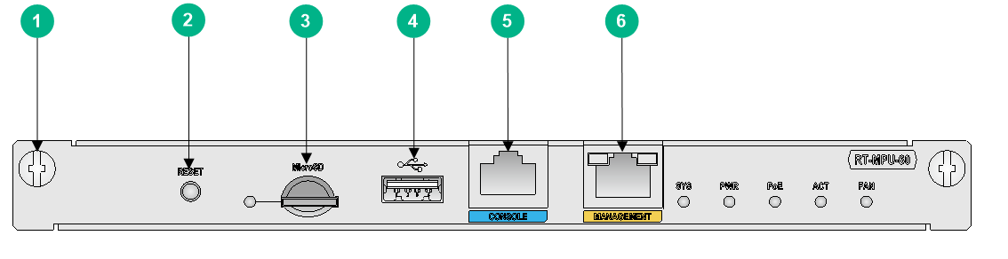
|
(1) Captive screw |
(2) Reset button (RESET) |
(3) Micro SD card slot |
|
(4) USB port |
(5) Console port |
(6) Management Ethernet port |
MPU-100
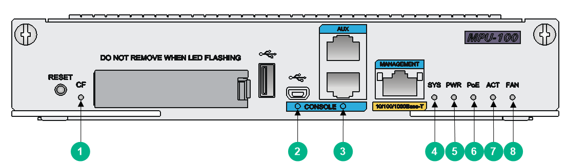
Figure2-2 MPU-100 front panel
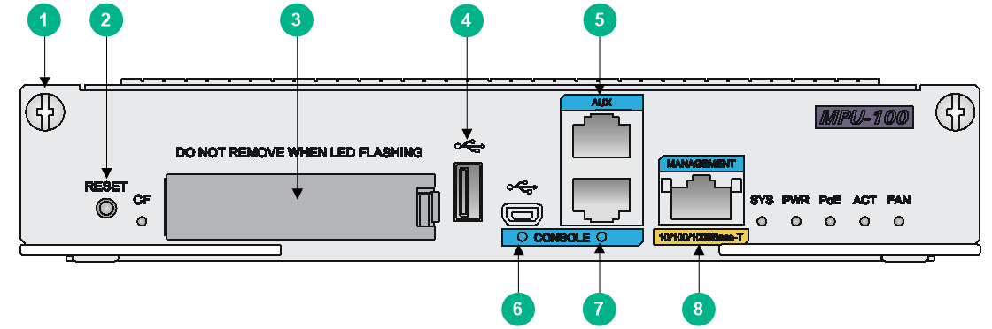
|
(1) Captive screw |
(2) Reset button (RESET) |
(3) CF card slot |
|
(4) USB port |
(5) AUX port |
(6) Mini USB console port |
|
(7) Console port |
(8) Management Ethernet port |
|
MPU-100-X1
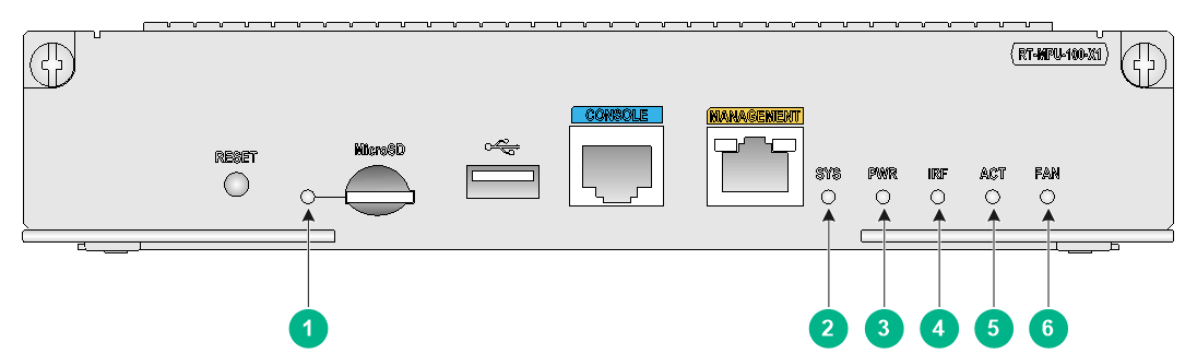
Figure2-3 MPU-100-X1 front panel

|
(1) Captive screw |
(2) Reset button (RESET) |
(3) Micro SD card slot |
|
(4) USB port |
(5) Console port |
(6) Management Ethernet port |
MPU-100-G
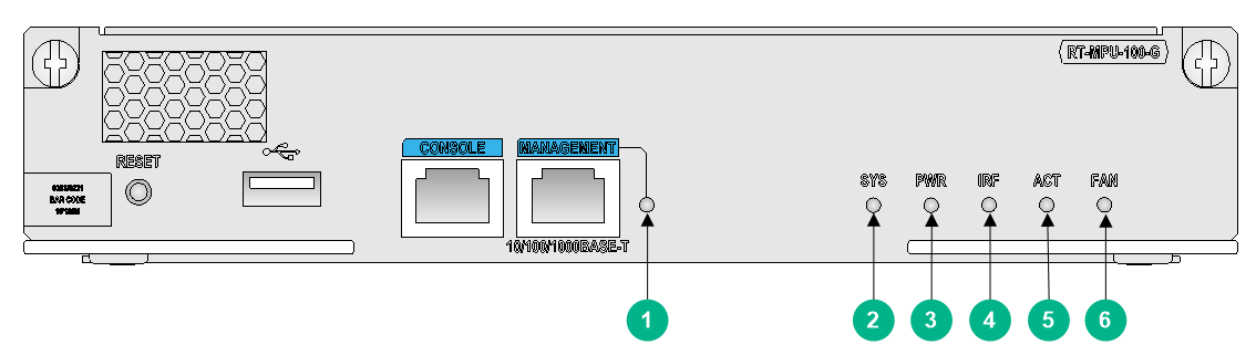
Figure2-4 MPU-100-G front panel
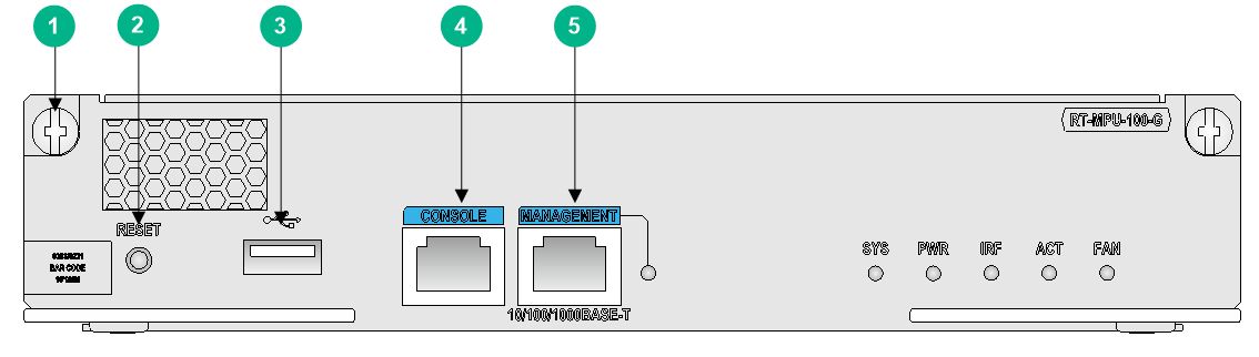
|
(1) Captive screw |
(2) Reset button (RESET) |
(3) USB port |
|
(4) Console port |
(5) Management Ethernet port |
|
SPUs and SPEs
SPU-100
Figure2-5 SPU-100 front panel
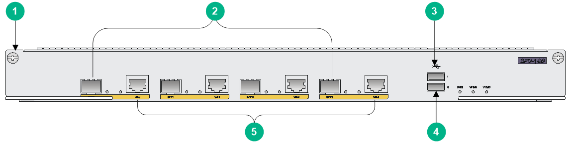
|
(1) Captive screw |
(2) Ethernet fiber ports SFP0 to SFP3 |
|
(3) USB port 1 |
(4) USB port 0 |
|
(5) Ethernet copper ports GE0 to GE3 |
|
SPU-200
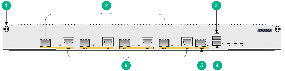
Figure2-6 SPU-200 front panel
|
(1) Captive screw |
(2) Ethernet fiber ports SFP0 to SFP3 |
|
(3) USB port 1 |
(4) USB port 0 |
|
(5) SFP+ port |
(6) Ethernet copper ports GE0 to GE3 |
SPU-300
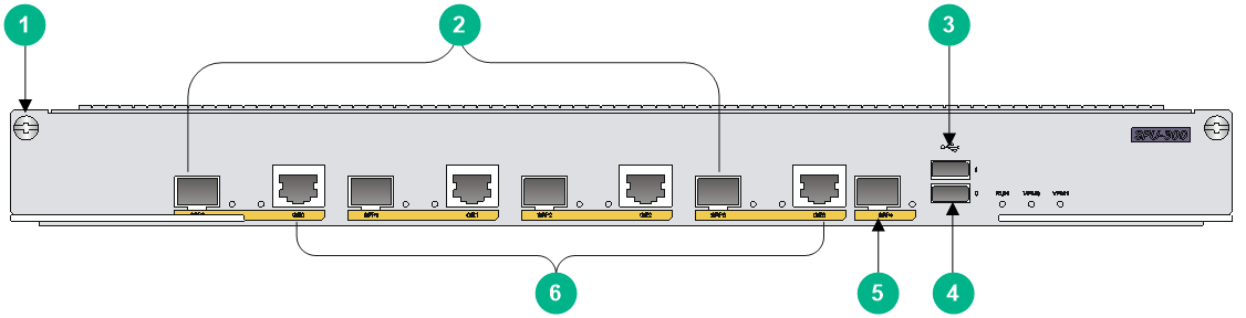
Figure2-7 SPU-300 front panel
|
(1) Captive screw |
(2) Ethernet fiber ports SFP0 to SFP3 |
|
(3) USB port 1 |
(4) USB port 0 |
|
(5) SFP+ port |
(6) Ethernet copper ports GE0 to GE3 |
SPU-100-X1
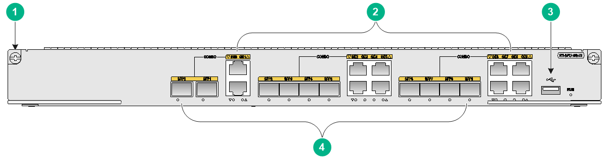
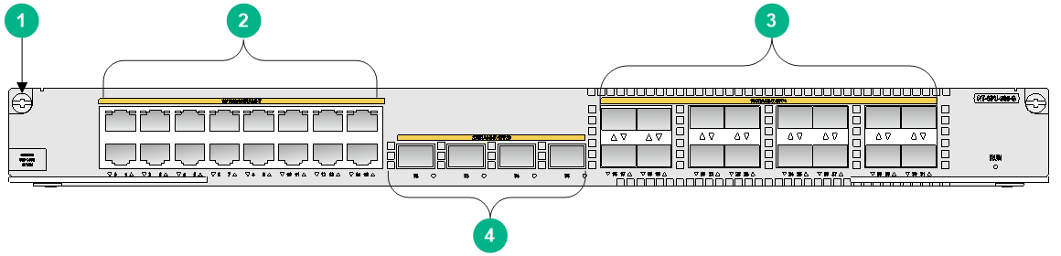
Figure2-8 SPU-100-X1 front panel
|
(1) Captive screw |
(2) Ethernet copper ports GE0 to GE9 |
(3) USB port |
|
(4) Ethernet fiber ports SFP0 to SFP9 |
||
SPU-200-X1
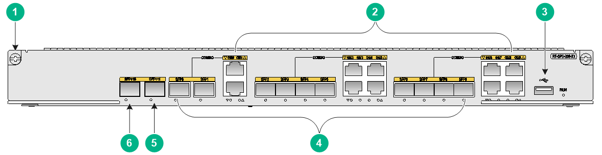
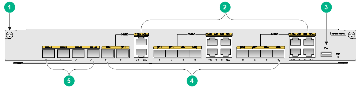
Figure2-9 SPU-200-X1 front panel
|
(1) Captive screw |
(2) Ethernet copper ports GE0 to GE9 |
(3) USB port |
|
(4) Ethernet fiber ports SFP0 to SFP9 |
(5) SFP+11 port |
(6) SFP+10 port |
SPU-300-G
Figure2-10 SPU-300-G front panel
|
(1) Captive screw |
(2) 10/100/1000BASE-T copper ports 0 to 15 |
|
(3) 10GBASE-R-SFP+ fiber ports 16 to 31 |
(4) 25GBASE-R-SFP28 fiber ports 32 to 35 |
SPU-400-X1
Figure2-11 SPU-400-X1 front panel
|
(1) Captive screw |
(2) Ethernet copper ports GE0 to GE9 |
(3) USB port |
|
(4) Ethernet fiber ports SFP0 to SFP9 |
(5) SFP+ ports SFP+10 to SFP+13 |
|
SPU-600-X1
Figure2-12 SPU-600-X1 front panel
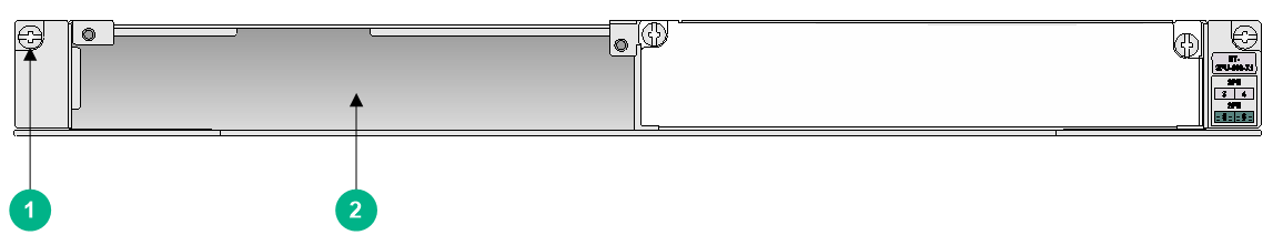
|
(1) Captive screw |
(2) SPE slot |
SPE-S1
Figure2-13 SPE-S1 front panel

|
(1) Captive screw |
(2) Ethernet copper ports GE0 to GE3 |
|
(3) Ethernet fiber ports SFP0 to SFP7 |
|
SPE-S3
Figure2-14 SPE-S3 front panel
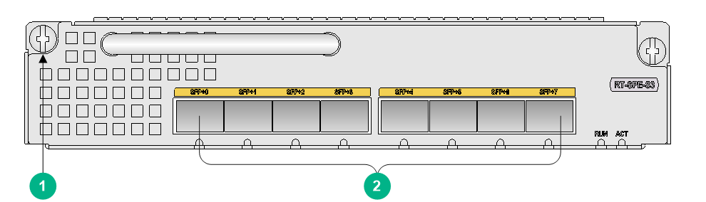
|
(1) Captive screw |
(2) Ethernet fiber ports SFP+0 to SFP+7 |
Power supplies
|
|
IMPORTANT: · To install multiple power supplies for the router, make sure they are all AC or DC power supplies. · The power system provides a PoE output capacity of 450 W when a PoE power supply is installed regardless of whether other power supplies are installed or not. |
AC power supply
Figure2-15 PSR300-12A2 power supply
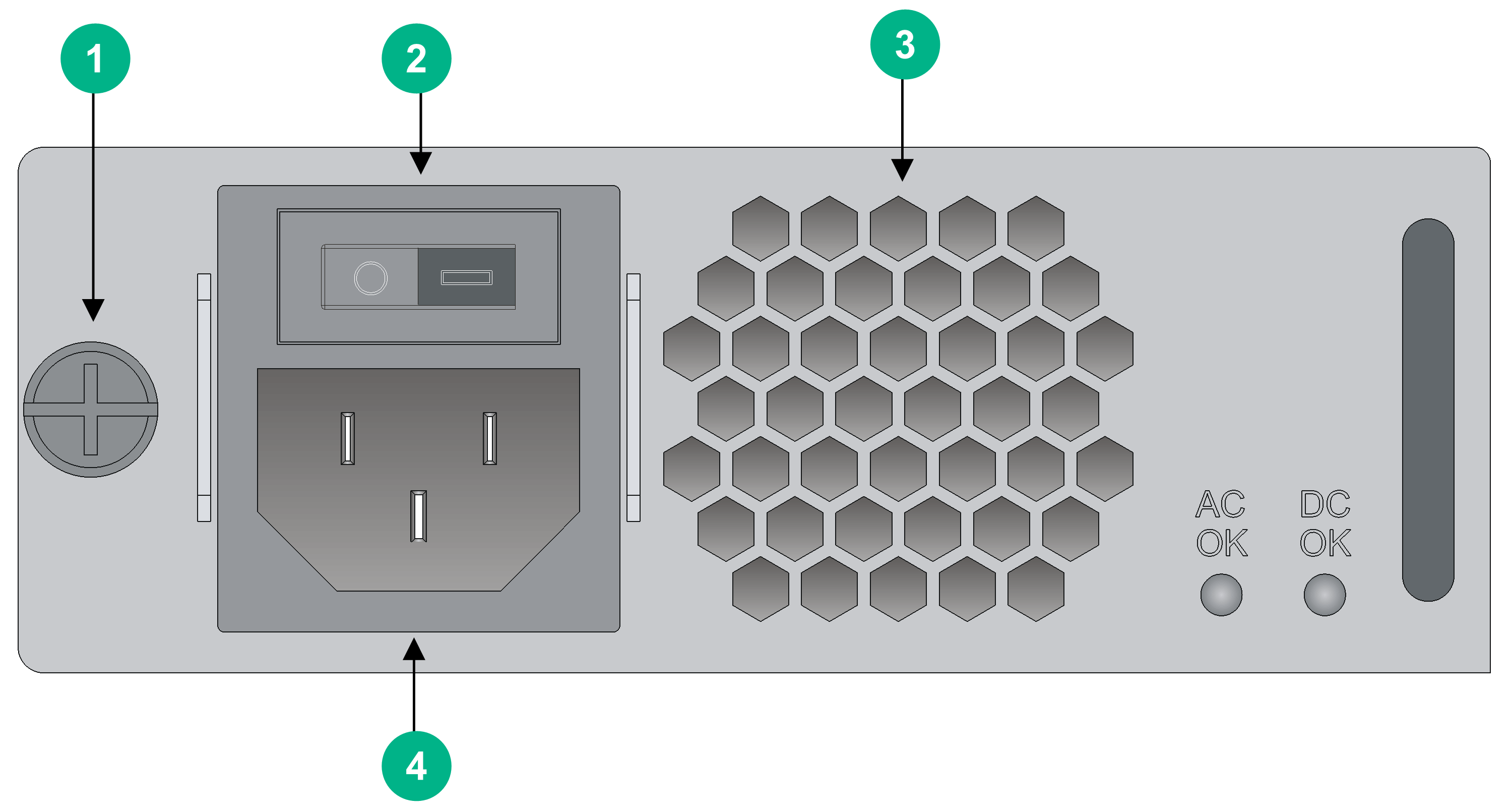
|
(1) Captive screw |
(2) Power switch |
|
(3) Air outlet vents |
(4) Power receptacle |
DC power supply
Figure2-16 PSR300-12D2 power supply
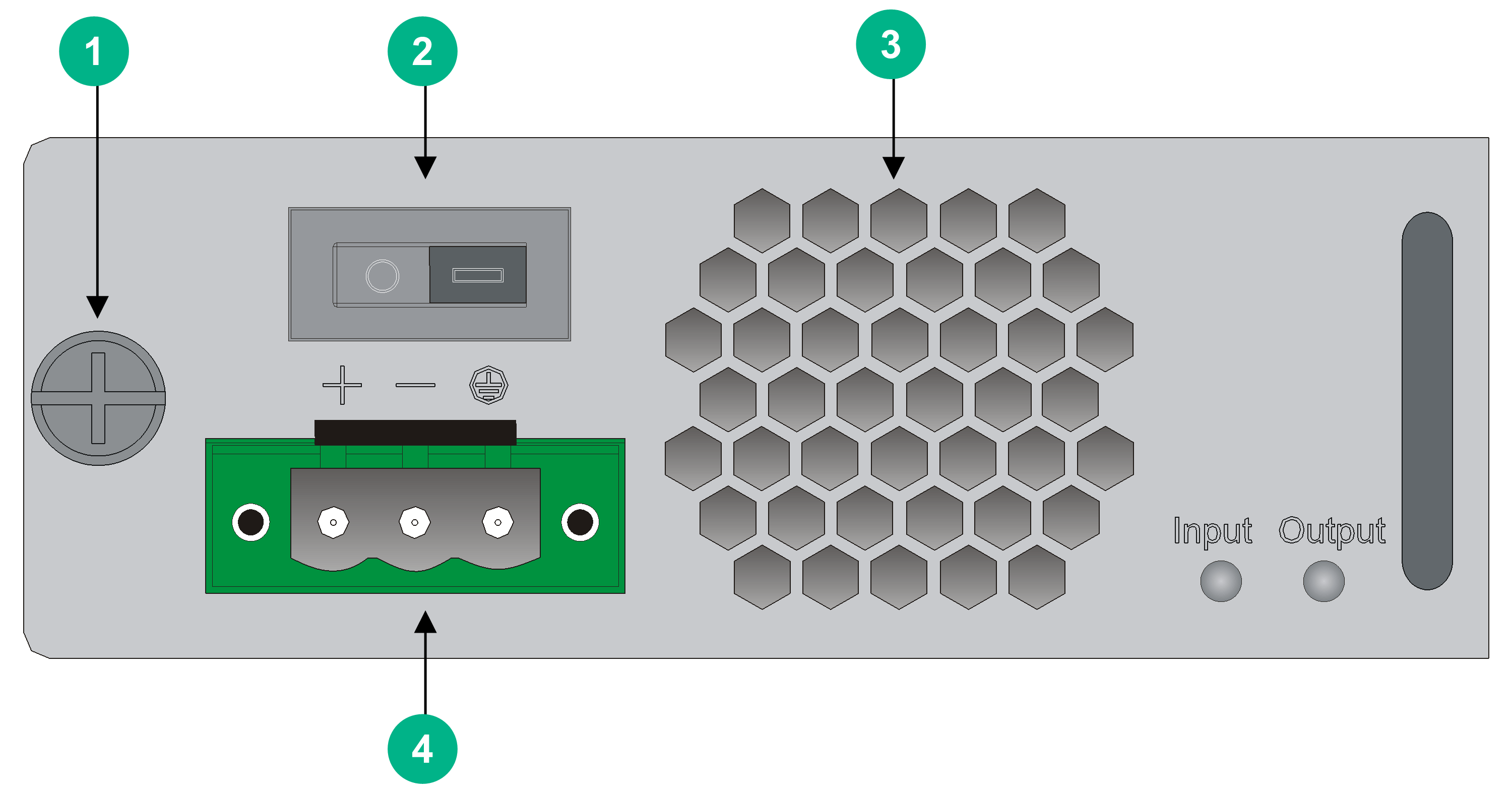
|
(1) Captive screw |
(2) Power switch |
|
(3) Air outlet vents |
(4) Power receptacle |
PoE power supply
Figure2-17 PSR750-A power supply
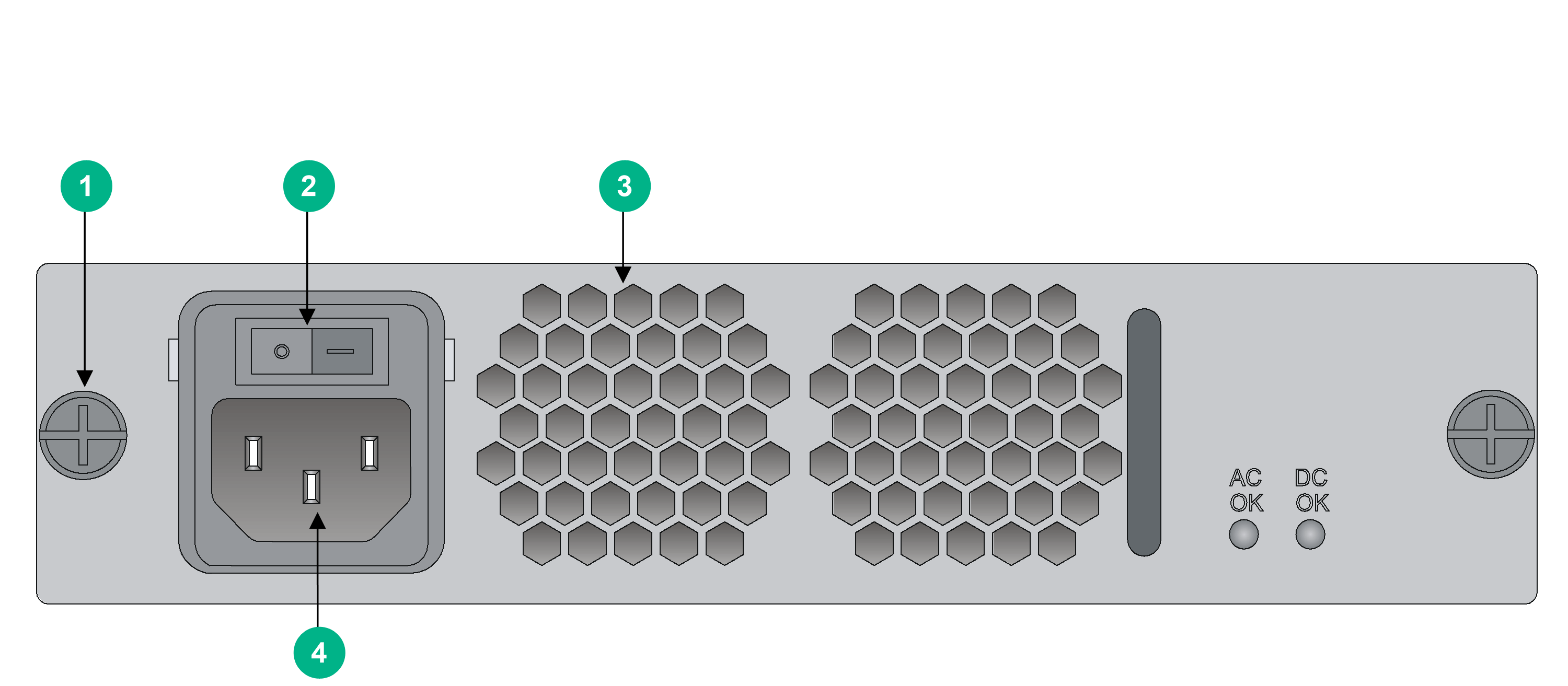
|
(1) Captive screw |
(2) Power switch |
|
(3) Air outlet vents |
(4) Power receptacle |
Technical specifications
MPUs
Table2-1 MPU specifications
|
Item |
MPU-60 |
MPU-100 |
MPU-100-X1 |
MPU-100-G |
|
Console port |
1 |
1 |
1 |
1 |
|
AUX port |
N/A |
1 |
N/A |
N/A |
|
GE management port |
1 |
1 |
1 |
1 |
|
USB console port |
N/A |
1 |
N/A |
N/A |
|
USB port |
1 |
1 |
1 |
1 |
|
Memory |
2 GB DDR3 |
2 GB DDR3 |
2 GB DDR3 |
4 GB DDR4 |
|
CF card |
N/A |
· Built-in: 512 MB · External: a maximum of 4 GB (optional) |
N/A |
N/A |
|
CF card slot |
N/A |
1 |
N/A |
N/A |
|
Built-in Micro SD card |
N/A |
N/A |
8 GB |
N/A |
|
Micro SD card slot |
1 (read/write rate: 100 Mbps, maximum capacity: 8 GB) |
N/A |
1 (read/write rate: 100 Mbps, maximum capacity: 8 GB) |
N/A |
|
SSD drive slot |
N/A |
N/A |
1 (mSATA SSD) |
N/A |
|
Flash |
512 MB |
8 MB |
N/A |
2*16 MB (in redundancy) |
SPUs
Table2-2 SPU specifications (1)
|
Item |
MSR5620 SPU |
SPU-100 |
SPU-200 |
SPU-300 |
|
|
USB port |
2 |
2 |
2 |
2 |
|
|
VPM slot |
0 |
2 |
2 |
2 |
|
|
Combo interface |
3 · SFP0/GE0 · SFP1/GE1 · SFP2/GE2 |
4 · SFP0/GE0 · SFP1/GE1 · SFP2/GE2 · SFP3/GE3 |
4 · SFP0/GE0 · SFP1/GE1 · SFP2/GE2 · SFP3/GE3 |
4 · SFP0/GE0 · SFP1/GE1 · SFP2/GE2 · SFP3/GE3 |
|
|
SFP+ port |
2 |
N/A |
1 |
1 |
|
|
SIC slot |
4 SIC slots |
N/A |
N/A |
N/A |
|
|
Memory |
2 GB DDR3 |
2 GB DDR3 |
2 GB DDR3 |
4 GB DDR3 |
|
|
Applicable router model |
MSR5620 |
MSR 56-60/56-80 |
|||
|
Applicable MPU |
MPU-60 |
MPU-100/MPU-100-X1 |
|||
Table2-3 SPU specifications (2)
|
Item |
SPU-100-X1 |
SPU-200-X1 |
SPU-400-X1 |
SPU-300-G |
|
USB port |
1 |
1 |
1 |
1 |
|
VPM slot |
N/A |
N/A |
N/A |
N/A |
|
Combo interface |
10 · SFP0/GE0 · SFP1/GE1 · SFP2/GE2 · SFP3/GE3 · SFP4/GE4 · SFP5/GE5 · SFP6/GE6 · SFP7/GE7 · SFP8/GE8 · SFP9/GE9 |
10 · SFP0/GE0 · SFP1/GE1 · SFP2/GE2 · SFP3/GE3 · SFP4/GE4 · SFP5/GE5 · SFP6/GE6 · SFP7/GE7 · SFP8/GE8 · SFP9/GE9 |
10 · SFP0/GE0 · SFP1/GE1 · SFP2/GE2 · SFP3/GE3 · SFP4/GE4 · SFP5/GE5 · SFP6/GE6 · SFP7/GE7 · SFP8/GE8 · SFP9/GE9 |
N/A |
|
GE port |
N/A |
N/A |
N/A |
16 |
|
SFP port |
N/A |
N/A |
N/A |
N/A |
|
SFP+ port |
N/A |
2 |
4 |
16 |
|
SFP28 port |
N/A |
N/A |
N/A |
4 |
|
SIC slot |
N/A |
N/A |
N/A |
N/A |
|
Memory |
2 GB DDR3 |
2 GB DDR3 |
4 GB DDR3 |
8 GB DDR3 |
|
Applicable router model |
MSR 56-60/56-80 |
MSR 56-60/56-80 |
MSR 56-60/56-80 |
MSR 56-60/56-80 |
|
Applicable MPU |
MPU-100/MPU-100-X1 |
MPU-100/MPU-100-X1 |
MPU-100/MPU-100-X1 |
MPU-100-G |
Table2-4 SPU-600-X1 and SPE specifications
|
Item |
SPU-600-X1 |
SPE-S1 |
SPE-S3 |
|
Combo interface |
N/A |
4 · SFP0/GE0 · SFP1/GE1 · SFP2/GE2 · SFP3/GE3 |
N/A |
|
SFP port |
N/A |
4 |
N/A |
|
SFP+ port |
N/A |
N/A |
8 |
|
Memory |
N/A |
2 GB DDR3 |
8 GB DDR3 |
|
Applicable router model |
MSR 56-60/56-80 |
||
|
Applicable MPU |
MPU-100-X1 |
||
Port groups
Table2-5 Port groups on the router and SPUs
|
Router/SPU |
Port groups |
Description |
|
MSR5620 |
SFP+ ports 3 and 4 in a group |
When you use the speed command to change the speed of a port in a group, the speed of the other ports in the group will be changed simultaneously. After you execute the speed command, you must reboot the router or SPU for the command to take effect. |
|
SPU-200-X1 |
SFP+ ports 10 and 11 in a group |
|
|
SPU-300-G |
· 10GBASE-R-SFP+ fiber ports 16 to 19 in a group · 25GBASE-R-SFP28 fiber ports 32 to 35 in a group |
|
|
SPU-400-X1 |
SFP+ ports 10 to 13 in a group |
|
|
SPE-S3 |
· SFP+ ports 0 to 3 in a group · SFP+ ports 4 to 7 in a group |
Power supplies
Table2-6 AC power supply specifications
|
Item |
Specification |
|
Model |
PSR300-12A2 |
|
Rated input voltage range |
100 VAC to 240 VAC @ 50 Hz or 60 Hz |
|
Rated power |
300 W |
Table2-7 DC power supply specifications
|
Item |
Specification |
|
Model |
PSR300-12D2 |
|
Rated input voltage range |
–48 VDC to –60 VDC |
|
Rated power |
300 W |
Table2-8 PoE power supply specifications
|
Item |
Specification |
|
Model |
PSR750-A |
|
Rated input voltage range |
100 VAC to 240 VAC @ 50 Hz or 60 Hz |
|
Rated power |
· 300 W to the system · 450 W to PDs |
Power supply and router compatibility matrix
Table2-9 Power supply and router compatibility matrix
|
Power supply model |
Router |
||
|
MSR5620 |
MSR5620 |
MSR5620 |
|
|
PSR300-12A2 |
√ |
√ |
√ |
|
PSR300-12D2 |
√ |
√ |
√ |
|
PSR750-A |
× |
√ |
√ |
|
|
NOTE: · "√" indicates that the power supply is compatible with the chassis. · "×" indicates that the power supply is not compatible with the chassis. |
3 LEDs
Module LEDs
MPU LEDs
Figure3-1 MPU-60 LEDs
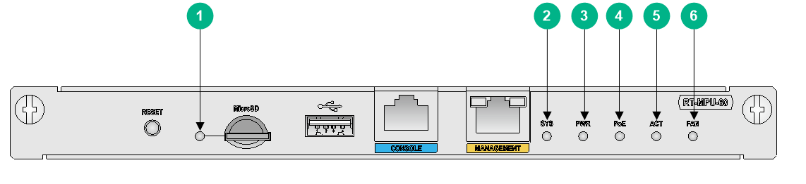
|
(1) Micro SD card LED |
(2) System status LED (SYS) |
(3) Power supply status LED (PWR) |
|
(4) PoE power supply status LED |
(5) MPU status LED (ACT) |
(6) Fan tray status LED (FAN) |
Figure3-2 MPU-100 LEDs
|
(1) CF card LED |
(2) USB console port LED |
(3) Console port LED |
|
(4) System status LED (SYS) |
(5) Power supply status LED (PWR) |
(6) PoE power supply status LED |
|
(7) MPU status LED (ACT) |
(8) Fan tray status LED (FAN) |
|
Figure3-3 MPU-100-X1 LEDs
|
(1) Micro SD card LED |
(2) System status LED (SYS) |
(3) Power supply status LED (PWR) |
|
(4) IRF status LED (IRF) |
(5) MPU status LED (ACT) |
(6) Fan tray status LED (FAN) |
Figure3-4 MPU-100-G LEDs
|
(1) Copper management Ethernet port LED |
(2) System status LED (SYS) |
|
(3) Power supply status LED (PWR) |
(4) IRF status LED |
|
(5) MPU status LED (ACT) |
(6) Fan tray status LED (FAN) |
SPU LEDs
Figure3-5 MSR5620 SPU LEDs
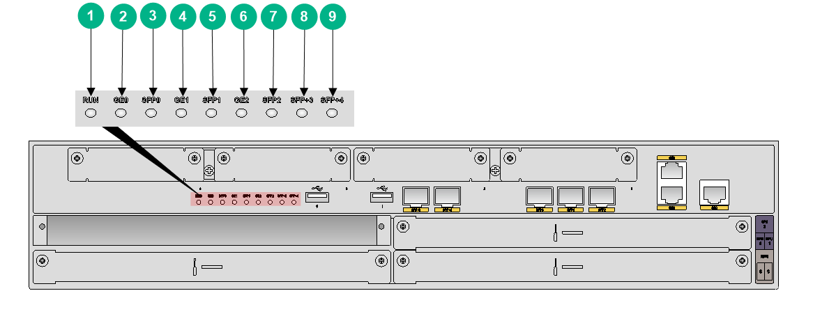
|
(1) SPU status LED (RUN) |
(2) GE0 port LED (GE0) |
(3) SFP0 port LED (SFP0) |
|
(4) GE1 port LED (GE1) |
(5) SFP1 port LED (SFP1) |
(6) GE2 port LED (GE2) |
|
(7) SFP2 port LED (SFP2) |
(8) SFP+3 port LED (SFP+3) |
(9) SFP+4 port LED (SFP+4) |
Figure3-6 SPU-100 LEDs
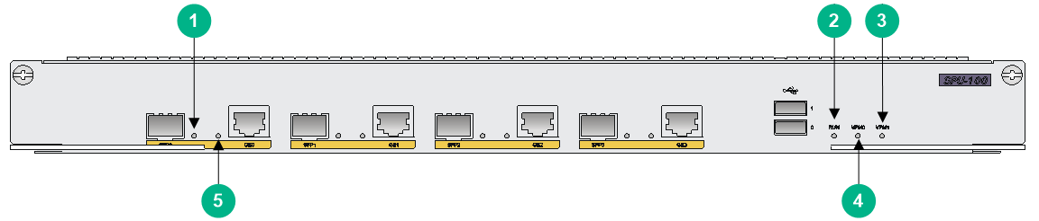
|
(1) SFP port LED |
(2) SPU status LED (RUN) |
(3) VPM1 slot status LED (VPM1) |
|
(4) VPM0 slot status LED (VPM0) |
(5) GE port LED |
|
Figure3-7 SPU-200 LEDs

|
(1) SFP port LED |
(2) SPU status LED (RUN) |
(3) VPM1 slot status LED (VPM1) |
|
(4) VPM0 slot status LED (VPM0) |
(5) SFP+ port LED |
(6) GE port LED |
Figure3-8 SPU-300 LEDs
|
(1) SFP port LED |
(2) SPU status LED (RUN) |
(3) VPM1 slot status LED (VPM1) |
|
(4) VPM0 slot status LED (VPM0) |
(5) SFP+ port LED |
(6) GE port LED |
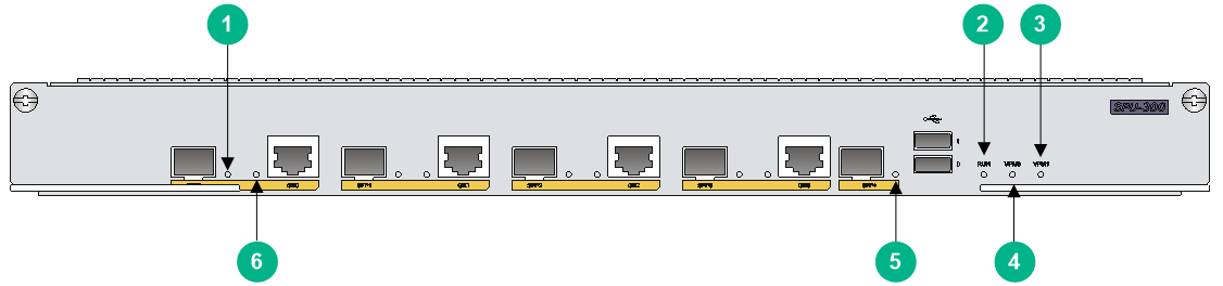
Figure3-9 SPU-100-X1 LEDs
|
(1) SFP port LED |
(2) GE port LED |
(3) SPU status LED (RUN) |
Figure3-10 SPU-200-X1 LEDs

|
(1) SFP+ port LED |
(2) SFP port LED |
(3) GE port LED |
|
(4) SPU status LED (RUN) |
||
Figure3-11 SPU-300-G LEDs

|
(1) 10/100/1000BASE-T copper port LED |
(2) 10GBASE-R-SFP+ fiber port LED |
|
(3) SPU status LED (RUN) |
(4) 25GBASE-R-SFP28 fiber port LED |
Figure3-12 SPU-400-X1 LEDs

|
(1) SFP+ port LED |
(2) SFP port LED |
(3) GE port LED |
|
(4) SPU status LED (RUN) |
||
SPE LEDs
Figure3-13 SPE-S1 LEDs
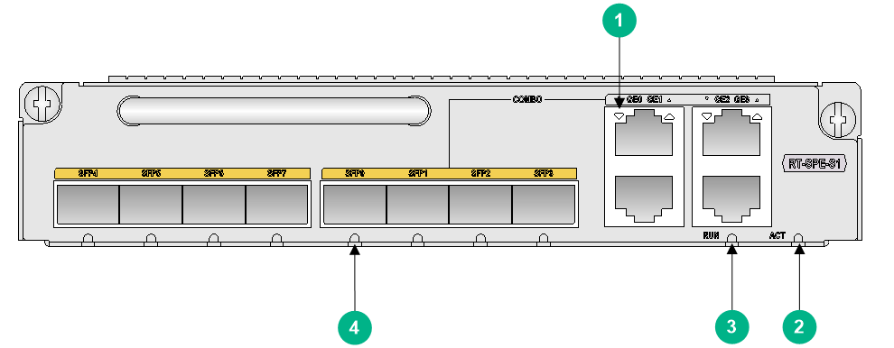
|
(1) GE port LED |
(2) SPE status LED (ACT) |
(3) SPE status LED (RUN) |
|
(4) SFP port LED |
||
Figure3-14 SPE-S3 LEDs
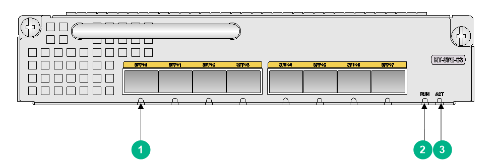
|
(1) SFP+ port LED |
(2) SPE status LED (RUN) |
(3) SPE status LED (ACT) |
LED descriptions
|
LED |
Location |
Status |
Description |
|
CF card LED |
MPU-100 |
Steady green |
A CF card is in position and the host has detected the CF card. |
|
Flashing green |
The CF card is performing read and write operations. Do not remove the CF card at this moment. |
||
|
Steady yellow |
The CF card has failed to pass the detection. |
||
|
Off |
No CF card is in position or the CF card cannot be identified. |
||
|
USB console port LED |
MPU-100 |
Off |
The USB console port configuration is not used. |
|
Steady on |
The USB console port configuration is in use. |
||
|
Micro SD card LED |
MPU-60 MPU-100-X1 |
Steady green |
A Micro SD card is present and has passed the test. |
|
Flashing green |
The system is reading from and writing to the Micro SD card. Do not remove the card during this process. |
||
|
Steady yellow |
The Micro SD card is faulty. |
||
|
Off |
No Micro SD card is present. |
||
|
Console port LED |
MPU-100 |
Off |
The serial console port configuration is not used. |
|
Steady on |
The serial console port configuration is in use. |
||
|
System status LED (SYS) |
MPU |
Steady green |
The system is performing power-on self-test (POST) for the memory. |
|
Fast flashing (green) |
The system is starting up. |
||
|
Slow flashing (green) |
The system is operating correctly. |
||
|
Fast flashing (yellow) |
The system file is lost. |
||
|
Slow flashing (yellow) |
The memory has failed to pass the POST. |
||
|
Steady yellow |
The system file does not exist. |
||
|
Off |
A system hardware fault has occurred. |
||
|
Power supply LED (PWR) |
MPU |
Off |
No power supply is installed or no power source is connected. |
|
Steady green |
The power supply is operating correctly. |
||
|
Steady yellow |
The power supply is faulty. |
||
|
PoE power supply LED |
MPU-60 MPU-100 |
Off |
No PoE power supply is installed or the PoE power supply is faulty. |
|
Steady green |
The PoE power supply is operating correctly. |
||
|
Steady yellow |
The PoE power supply is faulty. |
||
|
IRF status LED |
MPU-100-X1 MPU-100-G |
Flashing green at 1 Hz |
The router is in IRF mode and the MPU acts as the global active MPU. |
|
Steady green |
The router is in IRF mode and the MPU acts as a standby MPU. |
||
|
Off |
The router is in standalone mode. |
||
|
Steady yellow |
The router is in IRF mode but the IRF fabric has not been set up. |
||
|
MPU status LED (ACT) |
MPU |
Off |
The MPU is in standby state. |
|
Steady green |
The MPU is in active state. |
||
|
Fan tray status LED (FAN) |
MPU |
Off |
No fan tray is present. |
|
Steady green |
The fan tray is operating correctly. |
||
|
Steady yellow |
The fan tray is faulty. |
||
|
Copper management Ethernet port LED |
MPU-100-G |
Steady green |
A 1000 Mbps link is present on the port. |
|
Flashing green |
Data is being sent or received at 1000 Mbps. |
||
|
Steady yellow |
A 10/100 Mbps link is present on the port. |
||
|
Flashing yellow |
Data is being sent or received at 10/100 Mbps. |
||
|
Off |
No link is present. |
||
|
SPU/SPE status LED |
MSR5620 SPU SPU-100 SPU-200 SPU-300 SPU-100-X1 SPU-200-X1 SPU-300-G SPU-400-X1 SPE-S1 SPE-S3 |
Steady green |
Memory is being tested. |
|
Fast flashing green |
The system is starting up. |
||
|
Slow flashing green |
The system is operating correctly. |
||
|
Steady yellow |
No system file exists. |
||
|
Fast flashing yellow |
The system file is lost. |
||
|
Slow flashing yellow |
The memory test has failed. |
||
|
Off |
A hardware fault has occurred. |
||
|
SPE status LED (ACT) |
SPE-S1 SPE-S3 |
Steady green |
The SPE is in active state. |
|
Steady yellow |
The SPE is in standby state. |
||
|
VPM0 slot status LED |
SPU-100 SPU-200 SPU-300 |
Steady green |
A VPM is present and operating correctly. |
|
Steady yellow |
A VPM is present but faulty. |
||
|
Off |
No VPM is present. |
||
|
VPM1 slot status LED |
SPU-100 SPU-200 SPU-300 |
Steady green |
A VPM is present and operating correctly. |
|
Steady yellow |
A VPM is present but faulty. |
||
|
Off |
No VPM is present. |
||
|
SFP port LED |
MSR5620 SPU SPU-100 SPU-200 SPU-300 SPU-100-X1 SPU-200-X1 SPU-400-X1 SPE-S1 |
Off |
No link is present. |
|
Steady green |
A 1000 Mbps link is present. |
||
|
Flashing green |
Data is being sent or received at 1000 Mbps. |
||
|
Steady yellow |
The transceiver module has failed the test or a 100 Mbps link is present. |
||
|
Flashing yellow |
Data is being sent or received at 100 Mbps. |
||
|
GE port LED |
MSR5620 SPU SPU-100 SPU-200 SPU-300 SPU-100-X1 SPU-200-X1 SPU-300-G SPU-400-X1 SPE-S1 |
Off |
No link is present. |
|
Steady green |
A 1000 Mbps link is present. |
||
|
Flashing green |
Data is being sent or received at 1000 Mbps. |
||
|
Steady yellow |
A 10/100 Mbps link is present. |
||
|
Flashing yellow |
Data is being sent or received at 10/100 Mbps. |
||
|
SFP+ port LED |
MSR5620 SPU SPU-200-X1 SPU-400-X1 SPE-S3 |
Off |
No link is present on the port |
|
Steady green |
A 1000 Mbps/10 Gbps link is present on the port |
||
|
Flashing green |
Data is being sent or received at 1000 Mbps/10 Gbps. |
||
|
Steady yellow |
The transceiver module has failed the test. |
||
|
SFP+ port LED |
SPU-200 SPU-300 |
Off |
No link is present on the port |
|
Steady green |
A 10 Gbps link is present on the port |
||
|
Flashing green |
Data is being sent or received at 10 Gbps. |
||
|
Steady yellow |
The transceiver module has failed the test. |
||
|
10GBASE-R-SFP+ fiber port LED |
SPU-300-G |
Steady green |
A 10 Gbps link is present on the port. |
|
Flashing green |
Data is being sent or received at 10 Gbps. |
||
|
Steady yellow |
A 1000 Mbps link is present on the port. |
||
|
Flashing yellow |
Data is being sent or received at 1000 Mbps. |
||
|
Off |
No link is present on the port. |
||
|
25GBASE-R-SFP28 fiber port LED |
SPU-300-G |
Steady green |
A 25 Gbps link is present on the port. |
|
Flashing green |
Data is being sent or received at 25 Gbps. |
||
|
Steady yellow |
A 10 Gbps link is present on the port. |
||
|
Flashing yellow |
Data is being sent or received at 10 Gbps. |
||
|
Off |
No link is present on the port. |
Power supply LEDs
Figure3-15 AC power supply LEDs
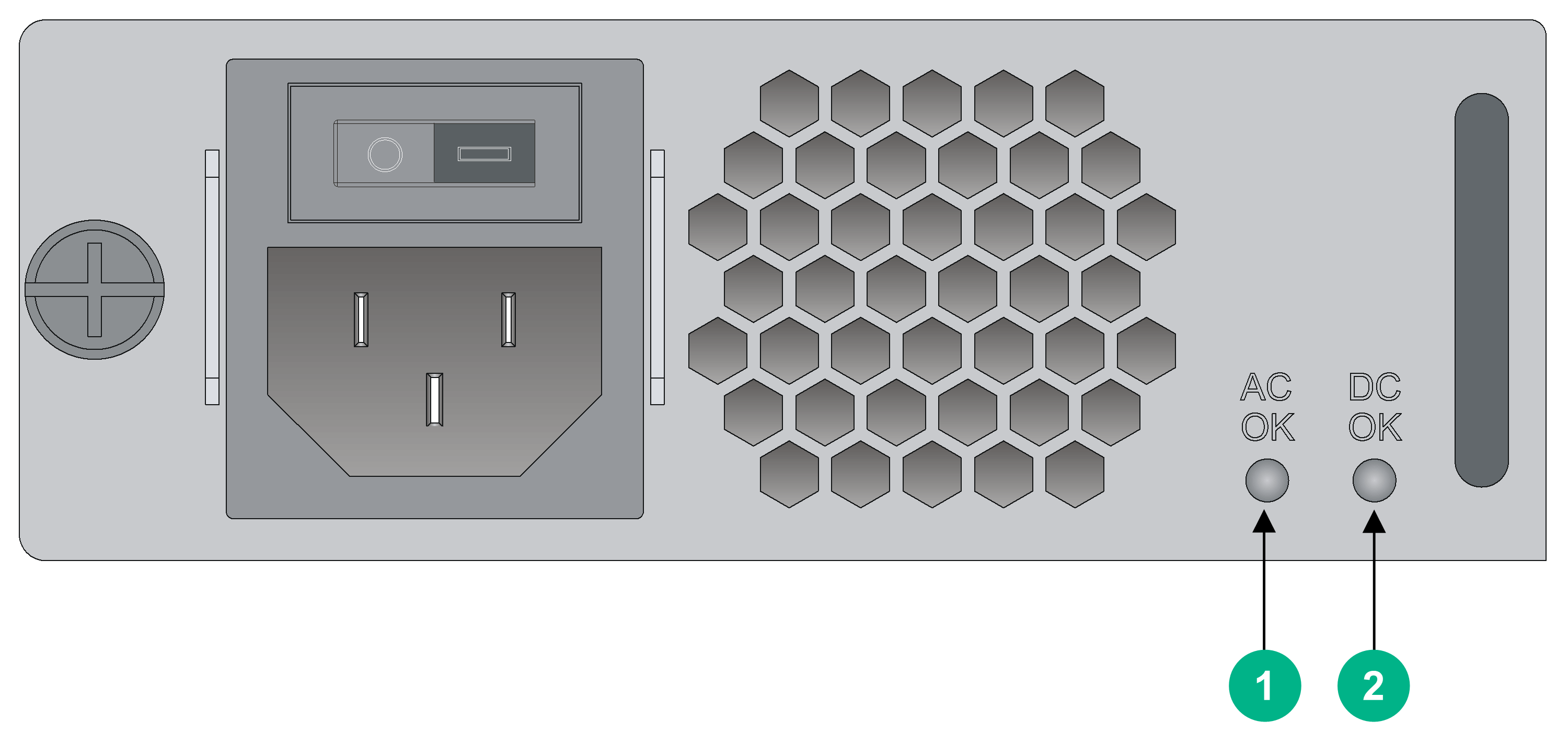
|
(1) Power input LED |
(2) Power output LED |
Figure3-16 DC power supply LEDs
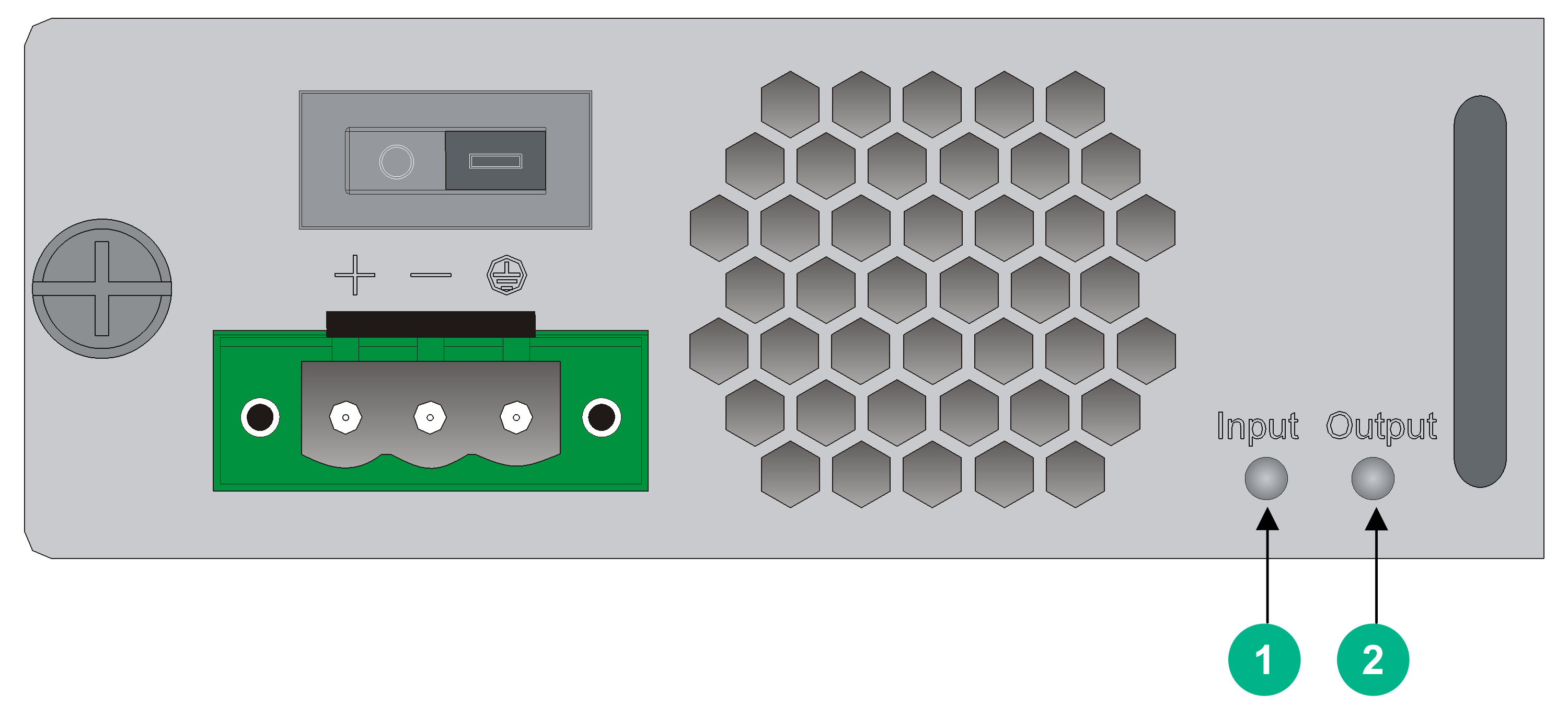
|
(1) Power input LED |
(2) Power output LED |
Figure3-17 PoE power supply LEDs
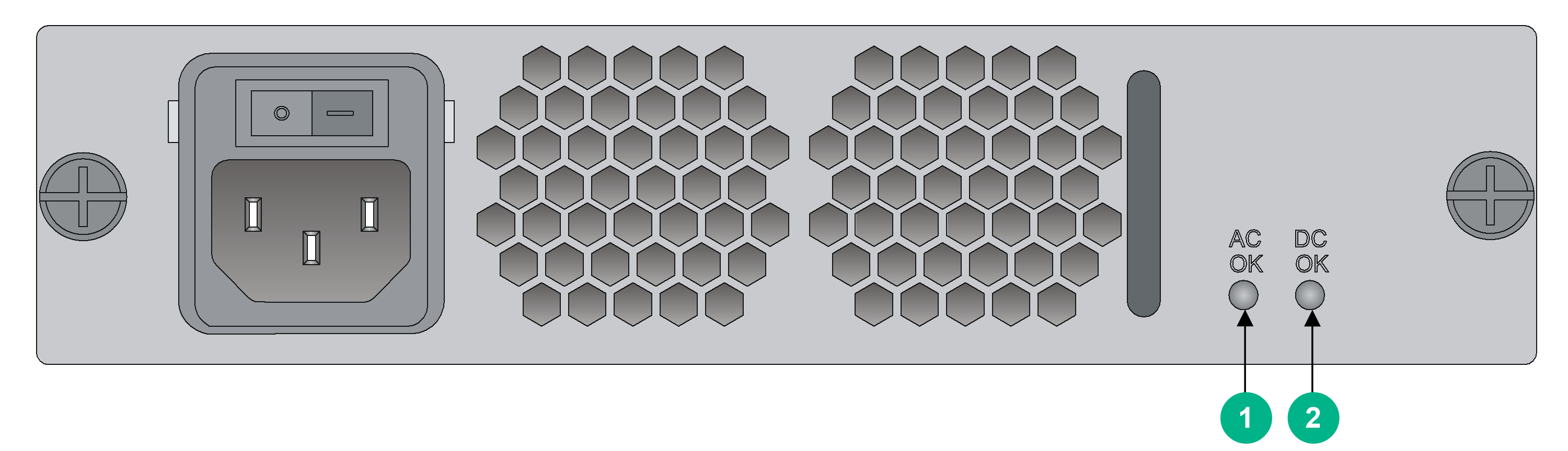
|
(1) Power input LED |
(2) Power output LED |
LED descriptions
Table3-2 LED descriptions
|
LED |
Location |
Status |
Description |
|
AC OK |
AC power supply |
Off |
No power input or the power input is faulty. |
|
Steady green |
The power is input correctly. |
||
|
DC OK |
AC power supply |
Off |
No power output or the power output is faulty. |
|
Steady green |
The power is output correctly. |
||
|
Input |
DC power supply |
Off |
No power input or the power input is faulty. |
|
Steady green |
The power is input correctly. |
||
|
Output |
DC power supply |
Off |
No power output or the power output is faulty. |
|
Steady green |
The power is output correctly. |
||
|
AC OK |
PoE power supply |
Off |
No power input or the power input is faulty. |
|
Steady green |
The power is input correctly. |
||
|
DC OK |
PoE power supply |
Off |
No power output or the power output is faulty. |
|
Steady green |
The power is output correctly. |
4 Slot arrangement and interface numbering
Table4-1 Slot arrangement and interface numbering
|
Model |
Slot arrangement |
Interface ID description |
|
MSR5620 |
|
In standalone mode: · For an MPU interface: ¡ AUX—MPU slot number/0/1. ¡ MGE—0. · For an SPU-600-X1 interface: SPE slot number/0/interface number. · For other SPU interfaces: 2/0/interface number. · For an HMIM interface (with an SPU-600-X1 installed): ¡ 5/even HMIM slot number/interface number. For example, GE5/4/0 is interface 0 on HMIM slot 4. ¡ 6/odd HMIM slot number/interface number. For example, GE6/5/0 is interface 0 on HMIM slot 5. · For an HMIM interface (with other SPUs installed): 2/HMIM slot number/interface number. For example, GE2/5/0 is interface 0 on HMIM slot 5. In IRF mode: · For an MPU interface: ¡ AUX—Chassis number/MPU slot number/0/1. ¡ MGE—0. · For an SPU interface: Chassis number/2/0/interface number. · For an HMIM interface: Chassis number/2/HMIM slot number/interface number. For example, GE1/2/5/0 is interface 0 on HMIM slot 5 of member device 1. |
|
MSR 56-60 |
|
|
|
MSR 56-80 |
|
|
|
SPU-600-X1 |
|
|
|
|
||