- Released At: 05-08-2022
- Page Views:
- Downloads:
- Related Documents
-
|
H3C Service Provider BRAS Configuration Examples |
|
|
|
Software version: Release 7951P01
Document version: 6W100-20200625
Copyright © 2020 New H3C Technologies Co., Ltd. All rights reserved.
No part of this manual may be reproduced or transmitted in any form or by any means without prior written consent of New H3C Technologies Co., Ltd.
Except for the trademarks of New H3C Technologies Co., Ltd., any trademarks that may be mentioned in this document are the property of their respective owners.
The information in this document is subject to change without notice.
Contents
General restrictions and guidelines· 1
Example: Configuring PPPoE in a residential network· 1
Configuration restrictions and guidelines· 4
Configuring the RADIUS server 4
Configuring interface IP addresses and routes· 5
Verifying the configuration· 8
Example: Configuring BRAS services by using PPPoE, IPoE, and multicast 13
Configuration restrictions and guidelines· 16
Introduction
This document provides BRAS configuration examples in service provider networks.
Prerequisites
The configuration examples in this document were created and verified in a lab environment, and all the devices were started with the factory default configuration. When you are working on a live network, make sure you understand the potential impact of every command on your network.
This document assumes that you have basic knowledge of IPoE, PPPoE, IRF, multicast, VLAN termination, and QinQ.
General restrictions and guidelines
These configuration examples are supported only by CSPEX cards (except CSPEX-1104-E), and CEPC cards when the device operates in standard mode. For more information about system operating modes, see device management in Fundamentals Configuration Guide.
Example: Configuring PPPoE in a residential network
Network configuration
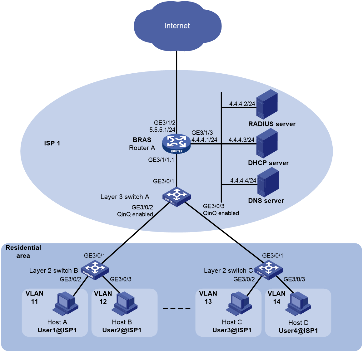
As shown in Figure 1, each of the three users (Host A, Host B, and Host C) in a residential area buys the 4 Mbps data plan from operator ISP1, and another user (Host D) buys the 10 Mbps data plan from the operator. Router A, as a BRAS of the operator, provides Internet access services for all the users through PPPoE. When users dial in through PPPoE, Router A dynamically assigns IP addresses to them through the DHCP relay agent and performs AAA on each user through a RADIUS server.
Configure the following settings to meet the scalability and security requirements of the operator:
· Configure Router A so it can meet the Internet access requirements (PPPoE dialup) of the users in the same residential area or in a different residential area.
· Configure attack prevention settings to prevent attacks.
Analysis
To meet the network requirements, you must perform the following tasks:
· To meet the bandwidth requirements of the users, authorize CAR settings through the RADIUS server.
· To improve the scalability in port usage and VLAN usage of the BRAS, enable QinQ (outer VLAN ID is service provider VLAN 101) on the Layer 3 switch (Switch A) of the ISP, and enable VLAN termination on a subinterface (GigabitEthernet 3/1/1.1 on the BRAS) for user access on the BRAS.
· For a DHCP relay agent to notify the DHCP server to release the IP address when a PPPoE user goes offline, enable recording client information in relay entries on the DHCP relay agent. When a PPPoE user goes offline, the DHCP relay agent can find a matching relay entry and send a DHCP-RELEASE message to the DHCP server.
· When DHCP works with PPPoE, you do not need to execute the dhcp select relay proxy command if the remote-server command is executed in DHCP address pool view.
· To ensure network security, configure the following attack protection settings:
Attack protection type | Attack protection measure | Command | Description |
Link layer attack protection | MAC-based user blocking | pppoe-server connection chasten | This feature prevents multiple PPPoE users from frequently coming online and going offline or prevent protocol packet attacks. After this feature is enabled, users who performs the following operations for the specified number of times within a period will be blocked: · Come online. · Go offline. · Send PPPoE connection requests. Packets from blocked users will be discarded during the blocking period, and will be processed after the blocking period expires. |
PPP user blocking | ppp authentication chasten | This feature blocks a PPP user for a period if the user fails authentication consecutively for the specified number of times within the detection period. This feature helps prevent illegal users from using the method of exhaustion to obtain the password, and reduces authentication packets sent to the authentication server. Packets from the blocked users will be discarded during the blocking period, and will be processed when the blocking period expires. | |
IP layer attack protection | uRPF | ip urpf strict | This feature prevents source address spoofing attacks. |
ICMP fast reply | ip icmp fast-reply enable | This feature allows the hardware to reply to the ICMP requests without delivering them to the CPU for processing. | |
Fast reply for keepalive packets | ppp keepalive fast-reply enable | This feature allows the hardware to automatically identify and reply to incoming keepalive requests, which can prevent DDoS attacks. This feature is supported only for Ethernet interfaces on CSPEX cards (except CSPEX-1204 and CSPEX-1104-E) and CEPC cards. | |
Application layer attack protection | DHCP flood attack protection | dhcp flood-protection enable | This feature enables the DHCP relay agent to detect DHCP flood attacks according to the DHCP packet rate threshold on a per-MAC basis. If the number of DHCP packets from the same MAC address reaches the upper limit, the DHCP relay agent discards subsequent DHCP packets from that client. |
PPPoE PADI attack protection | pppoe-server padi-limit | When device reboot or version update is performed, the burst of online requests might affect the device performance. To avoid device performance degradation and make sure the device can process PADI packets correctly, use this feature to adjust the PADI packet receiving rate limit. | |
User-based protocol packet rate limit | qos car user | The units at the control plane are processing units running most routing and switching protocols. They are responsible for protocol packet resolution and calculation, such as CPUs. Compared with user plane units, the control plane units allow for great packet processing flexibility but have lower throughput. When the user plane receives packets that it cannot recognize or process, it transmits them to the control plane. If the transmission rate exceeds the processing capability of the control plane, the control plane will be busy handling undesired packets. As a result, the control plane will fail to handle legitimate packets correctly or timely. As a result, protocol performance is affected. To address this problem, apply a QoS policy to the control plane to police inbound traffic. This ensures that the control plane can correctly receive, transmit, and process packets. This feature is supported only for CSPEX cards (except CSPEX-1204 and CSPEX-1104-E) and CEPC cards. |
Configuration restrictions and guidelines
If you configure an authorization IP address pool both in ISP domain view and on the RADIUS server, the authorization IP address pool configured on the RADIUS server is used. If you configure the idle-cut attribute both in ISP domain view and on the RADIUS server, the configuration in ISP domain view is used. In this configuration example, all authorization attributes are configured in ISP domain view.
Procedures
Configuring the RADIUS server
The following configuration uses a Linux-based Free RADIUS server as an example.
# Configure the RADIUS client by adding the following information to the clients.conf file:
client 4.4.4.1/32 {
ipaddr = 4.4.4.1
netmask=32
secret=123456
}
# Configure user information by adding the following information to the users file:
User1@isp1 Cleartext-Password :="pass1"
H3C_Input_Average_Rate = 4000000,
H3C_Output_Average_Rate = 4000000
User2@isp1 Cleartext-Password :="pass2"
H3C_Input_Average_Rate = 4000000,
H3C_Output_Average_Rate = 4000000
User3@isp1 Cleartext-Password :="pass3"
H3C_Input_Average_Rate = 4000000,
H3C_Output_Average_Rate = 4000000
User4@isp1 Cleartext-Password :="pass4"
H3C_Input_Average_Rate = 10000000,
H3C_Output_Average_Rate = 10000000
The information indicates that the username and password of Host A is User1@isp1/pass1 and Host A is rate limited to 4 Mbps. The username and password of Host B is User2@isp1/pass2, and Host B is rate limited to 4 Mbps. The username and password of Host C is User3@isp1/pass3, and Host C is rate limited to 4 Mbps. The username and password of Host D is User4@isp1/pass4, and Host C is rate limited to 10 Mbps.
Configuring interface IP addresses and routes
# Assign IP addresses to interfaces and configure routes. Make sure the network connections are available. (Details not shown.)
Configuring the DHCP server
# Enable DHCP.
<DHCP-server> system-view
[DHCP-server] dhcp enable
# Create a DHCP address pool named pool1 and enter its view.
[DHCP-server] dhcp server ip-pool pool1
# Configure the DHCP address pool to assign IP addresses and other configuration parameters to clients on subnet network 3.3.3.0/24.
[DHCP-server-pool-pool1] network 3.3.3.0 24
[DHCP-server-pool-pool1] gateway-list 3.3.3.1
[DHCP-server-pool-pool1] dns-list 4.4.4.5
# Exclude the gateway address from dynamic allocation.
[DHCP-server-pool-pool1] forbidden-ip 3.3.3.1
[DHCP-server-pool-pool1] quit
# Configure a static route to the PPPoE server (BRAS).
[DHCP-server] ip route-static 0.0.0.0 0 4.4.4.1
Configuring the BRAS
Configuring a RADIUS scheme
# Create a RADIUS scheme.
[BRAS] radius scheme rs1
# Specify the primary authentication server and primary accounting server, and set the shared keys to 123456 in plaintext form for authentication and accounting.
[BRAS-radius-rs1] primary authentication 4.4.4.2
[BRAS-radius-rs1] primary accounting 4.4.4.2
[BRAS-radius-rs1] key authentication simple 123456
[BRAS-radius-rs1] key accounting simple 123456
[BRAS-radius-rs1] quit
# Specify the DAC as 4.4.4.2. Set the shared key to 123456 in plaintext form for secure communication between the DAS and DAC.
[BRAS] radius dynamic-author server
[BRAS-radius-da-server] client ip 4.4.4.2 key simple 123456
[BRAS-radius-da-server] quit
Configuring a DHCP relay agent
# Enable DHCP.
[BRAS] dhcp enable
# Enable recording client information in relay entries.
[BRAS] dhcp relay client-information record
# Create a DHCP relay address pool, and configure the address pool to assign IP addresses and other configuration parameters to users.
[BRAS] dhcp server ip-pool pool1
[BRAS-dhcp-pool-pool1] gateway-list 3.3.3.1 export-route
[BRAS-dhcp-pool-pool1] remote-server 4.4.4.3
[BRAS-dhcp-pool-pool1] quit
Configuring an authentication domain
# Create an ISP domain named isp1 and enter ISP domain view.
[BRAS] domain name isp1
# Configure the ISP domain to use RADIUS scheme rs1 for authentication, authorization, and accounting.
[BRAS-isp-isp1] authentication ppp radius-scheme rs1
[BRAS-isp-isp1] authorization ppp radius-scheme rs1
[BRAS-isp-isp1] accounting ppp radius-scheme rs1
# Configure an authorization IP address pool for the ISP domain.
[BRAS-isp-isp1] authorization-attribute ip-pool pool1
[BRAS-isp-isp1] quit
Configuring a VT interface
# Create a VT interface, enable PPP accounting, and set the authentication mode to CHAP.
[BRAS] interface virtual-template 1
[BRAS-Virtual-Template1] ppp account-statistics enable
[BRAS-Virtual-Template1] ppp authentication-mode chap domain isp1
[BRAS-Virtual-Template1] quit
Configuring VLAN termination
# Configure ambiguous QinQ termination on GigabitEthernet 3/1/1.1, and enable the PPPoE server on the subinterface and bind it to the VT interface.
[BRAS] interface gigabitethernet 3/1/1.1
[BRAS-GigabitEthernet3/1/1.1] vlan-type dot1q vid 101 second-dot1q 11 to 14
[BRAS-GigabitEthernet3/1/1.1] pppoe-server bind virtual-template 1
Configuring attack protection
# Set the maximum number of PADI packets that slot 3 can receive per second to 500. The default setting is recommended. In this example, the default setting is 500. The default settings vary by MPU model. For more information, see the PPPoE command reference.
[BRAS] pppoe-server padi-limit slot 3 500
# Configure the BRAS to block a user for 300 seconds by its MAC address if the user sends 100 PPPoE connection requests within 600 seconds.
[BRAS] pppoe-server connection chasten 100 600 300
# Enable strict uRPF on the VT interface. By default, strict uRPF check is enabled.
[BRAS] interface virtual-template 1
[BRAS-Virtual-Template1] ip urpf strict
[BRAS-Virtual-Template1] quit
# Enable ICMP fast reply.
[BRAS] ip icmp fast-reply enable
# Enable fast reply for keepalive packets for slot 3. By default, fast reply is enabled for keepalive packets.
[BRAS] ppp keepalive fast-reply enable slot 3
# Enable DHCP flood attack protection on GigabitEthernet 3/1/1.1.
[BRAS] interface gigabitethernet 3/1/1.1
[BRAS-GigabitEthernet3/1/1.1] dhcp flood-protection enable
[BRAS-GigabitEthernet3/1/1.1] quit
Configuring Switch A
# Create a service provider VLAN numbered 101.
<SwitchA> system-view
[SwitchA] vlan 101
[SwitchA-vlan101] quit
# Configure GigabitEthernet 3/0/1 as a hybrid port, and assign it to VLAN 101 as a tagged member.
[SwitchA] interface gigabitethernet 3/0/1
[SwitchA-GigabitEthernet3/0/1] port link-type hybrid
[SwitchA-GigabitEthernet3/0/1] port hybrid vlan 101 tagged
[SwitchA-GigabitEthernet3/0/1] quit
# Configure GigabitEthernet 3/0/2 and GigabitEthernet 3/0/3 as trunk ports, and assign them to VLAN 101.
[SwitchA] interface range gigabitethernet 3/0/2 to gigabitethernet 3/0/3
[SwitchA-if-range] port link-type trunk
[SwitchA-if-range] port trunk permit vlan 101
# Set the PVID for the trunk ports to VLAN 101, and enable QinQ on them.
[SwitchA-if-range] port trunk pvid vlan 101
[SwitchA-if-range] qinq enable
[SwitchA-if-range] quit
Configuring Switch B
# Create customer VLANs numbered 11 and 12.
[SwitchB] vlan 11 to 12
# Configure GigabitEthernet 3/0/1 as a trunk port, and assign it to VLAN 11 and VLAN 12.
[SwitchB] interface gigabitethernet 3/0/1
[SwitchB-GigabitEthernet3/0/1] port link-type trunk
[SwitchB-GigabitEthernet3/0/1] port trunk permit vlan 11 12
[SwitchB-GigabitEthernet3/0/1] quit
# Assign GigabitEthernet 3/0/2 to VLAN 11.
[SwitchB] interface gigabitethernet 3/0/2
[SwitchB-GigabitEthernet3/0/2] port access vlan 11
[SwitchB-GigabitEthernet3/0/2] quit
# Assign GigabitEthernet 3/0/3 to VLAN 12.
[SwitchB] interface gigabitethernet 3/0/3
[SwitchB-GigabitEthernet3/0/3] port access vlan 12
[SwitchB-GigabitEthernet3/0/3] quit
Configuring Switch C
# Create customer VLANs numbered 13 and 14.
[SwitchC] vlan 13 to 14
# Configure GigabitEthernet 3/0/1 as a trunk port, and assign it to VLAN 13 and VLAN 14.
[SwitchC] interface gigabitethernet 3/0/1
[SwitchC-GigabitEthernet3/0/1] port link-type trunk
[SwitchC-GigabitEthernet3/0/1] port trunk permit vlan 13 14
[SwitchC-GigabitEthernet3/0/1] quit
# Assign GigabitEthernet 3/0/2 to VLAN 13.
[SwitchC] interface gigabitethernet 3/0/2
[SwitchC-GigabitEthernet3/0/2] port access vlan 13
[SwitchC-GigabitEthernet3/0/2] quit
# Assign GigabitEthernet 3/0/3 to VLAN 14.
[SwitchC] interface gigabitethernet 3/0/3
[SwitchC-GigabitEthernet3/0/3] port access vlan 14
[SwitchC-GigabitEthernet3/0/3] quit
Verifying the configuration
# Verify that the user at Host A can use username User1@isp1 and password pass1 to dial in to the BRAS to access the Internet.
# Verify that Host A has obtained an IP address through DHCP.
[BRAS] display dhcp relay client-information
Total number of client-information items: 1
Total number of dynamic items: 1
Total number of temporary items: 0
IP address MAC address Type Interface VPN name
3.3.3.2 e839-3563-fb21 Dynamic BAS0 N/A
# Display detailed information about user User1@isp1.
[BRAS] display ppp access-user username User1@isp1 verbose
Basic:
Interface: BAS0
PPP index: 0x140000105
User ID: 0x20000001
Username: User1@isp1
Domain: isp1
Access interface: GE3/1/1.1
Service-VLAN/Customer-VLAN: 101/11
VXLAN ID: -
MAC address: e839-3563-fb21
IP address: 3.3.3.2
Primary DNS server: 4.4.4.5
IPv6 address: -
IPv6 PD prefix: -
IPv6 ND prefix: -
User address type: N/A
VPN instance: -
Access type: PPPoE
Authentication type: CHAP
PPPoE:
Session ID: 1
AAA:
Authentication state: Authenticated
Authorization state: Authorized
Realtime accounting switch: Open
Realtime accounting interval: 900s
Login time: 2014-11-6 8:31:31:725
Accounting start time: 2014-11-6 8:31:32:275
Online time(hh:mm:ss): 0:3:46
Accounting state: Accounting
Acct start-fail action: Online
Acct update-fail action: Online
Acct quota-out action: Offline
Dual-stack accounting mode: Merge
Idle cut: 0 sec 0 byte, direction: Both
Session timeout: -
Time remained: -
Traffic quota: -
Traffic remained: -
Redirect WebURL: -
ITA policy name: -
MRU: 1480 bytes
IPv4 MTU: 1480 bytes
IPv6 MTU: 1480 bytes
Subscriber ID: -
ACL&QoS:
User profile: -
Session group profile: -
User group acl: -
Inbound CAR: CIR 4000 kbps PIR 4000 kbps CBS - (active)
Outbound CAR: CIR 4000 kbps PIR 4000 kbps CBS - (active)
User inbound priority: -
User outbound priority: -
Flow Statistic:
IPv4 uplink packets/bytes: 508/53292
IPv4 downlink packets/bytes: 285/26198
IPv6 uplink packets/bytes: 0/0
IPv6 downlink packets/bytes: 0/0
The output shows that Host A has successfully dialed in to the BRAS and obtained IP address 3.3.3.2.
# Display information about blocked PPP users after Host A failed to authenticate for three consecutive times in 60 seconds.
[BRAS] display ppp chasten user blocked
Username Domain Aging(s)
test isp1 280
The output shows that the BRAS drops packets from Host A within 280 seconds.
# Display information about blocked PPPoE users after Host A initiated 100 dial requests in 600 seconds.
[BRAS] display pppoe-server chasten user
Type: N-non-Quickoffline Q-Quickoffline
MAC/Option105 VLAN ID Interface Aging(S) Type Drops
e839-3563-fb21 101 GE3/1/1.1 288 N 1000
The output shows that the BRAS drops packets from Host A within 288 seconds.
Configuration files
· DHCP server:
#
dhcp enable
#
dhcp server ip-pool pool1
network 3.3.3.0 mask 255.255.255.0
dns-list 4.4.4.5
forbidden-ip 3.3.3.1
gateway-list 3.3.3.1
#
interface GigabitEthernet3/0/1
port link-mode route
ip address 4.4.4.3 255.255.255.0
#
ip route-static 0.0.0.0 0 4.4.4.1
#
· BRAS:
#
ip icmp fast-reply enable
#
dhcp enable
dhcp relay client-information record
#
dhcp server ip-pool pool1
gateway-list 3.3.3.1 export-route
remote-server 4.4.4.3
#
interface Virtual-Template1
ppp authentication-mode chap domain isp1
ppp account-statistics enable
#
interface GigabitEthernet3/1/2
port link-mode route
ip address 5.5.5.1 255.255.255.0
#
interface GigabitEthernet3/1/2
port link-mode route
#
interface GigabitEthernet3/1/1.1
vlan-type dot1q vid 101 second-dot1q 11 to 14
pppoe-server bind virtual-template 1
dhcp flood-protection enable
#
interface GigabitEthernet3/1/3
port link-mode route
ip address 4.4.4.1 255.255.255.0
#
radius scheme rs1
primary authentication 4.4.4.2
primary accounting 4.4.4.2
key authentication cipher $c$3$WyjH/HQEi8lmN/BiIW7W0HS4ewgPHFTlew==
key accounting cipher $c$3$bbpWnYU4Ynat3ddQB+IPRb3X5FgIsLXUgQ==
#
radius dynamic-author server
client ip 4.4.4.2 key cipher $c$3$Td30doCnLkhF7bhiYp4bk9DU96+XBStLkA==
#
domain name isp1
authorization-attribute ip-pool pool1
authentication ppp radius-scheme rs1
authorization ppp radius-scheme rs1
accounting ppp radius-scheme rs1
#
pppoe-server connection chasten 100 600 300
#
· Switch A:
#
vlan 101
#
interface GigabitEthernet3/0/1
port link-mode bridge
port link-type hybrid
port hybrid vlan 101 tagged
port hybrid vlan 1 untagged
#
interface GigabitEthernet3/0/2
port link-mode bridge
port link-type trunk
port trunk permit vlan 101
port trunk pvid vlan 101
qinq enable
#
interface GigabitEthernet3/0/3
port link-mode bridge
port link-type trunk
port trunk permit vlan 101
port trunk pvid vlan 101
qinq enable
#
· Switch B:
#
vlan 11 to 12
#
interface GigabitEthernet3/0/1
port link-mode bridge
port link-type trunk
port trunk permit vlan 11 12
#
interface GigabitEthernet3/0/2
port link-mode bridge
port access vlan 11
#
interface GigabitEthernet3/0/3
port link-mode bridge
port access vlan 12
#
· Switch C:
#
vlan 13 to 14
#
interface GigabitEthernet3/0/1
port link-mode bridge
port link-type trunk
port trunk permit vlan 13 14
#
interface GigabitEthernet3/0/2
port link-mode bridge
port access vlan 13
#
interface GigabitEthernet3/0/3
port link-mode bridge
port access vlan 14
#
Example: Configuring BRAS services by using PPPoE, IPoE, and multicast
Network configuration
As shown in Figure 2, Router A and Router B are two BRASs of an ISP that provide Internet access services for home users and enterprise users. For reliability, form an IRF fabric between Router A and Router B.
Router C is connected to the multicast source through Ten-GigabitEthernet 3/1/4. The multicast source sends multicast data to multicast group 224.1.1.1. PIM-DM runs between Router C and the IRF fabric. IGMPv2 runs on the IRF fabric. IGMPv2 snooping runs on Switch A. The IRF fabric acts as the IGMP querier.
Configure BRAS services to meet the following requirements:
· Home user Host A uses username User@isp1 and password radius to access the Internet through PPPoE and is rate limited to 8 Mbps. Accounting is performed on Host A.
· Home user the STB uses username MAC@iptv and password Option 60 to access the Internet through DHCP+IPoE and is rate limited to 4 Mbps. Accounting is performed on the STB.
· Enterprise user Host B uses username MAC@isp2 and password radius to access the Internet through DHCP+IPoE and is rate limited to 10 Mbps. Accounting is performed on Host B. Host B receives the multicast data from multicast group 224.1.1.1.
· Enterprise user the printer uses username MAC@print and password radius to access the Internet through static IPoE and is rate limited to 2 Mbps. Accounting is not performed on the printer.
· Dynamically assign IP addresses to the users that access through PPPoE or DHCP+IPoE by using the DHCP relay method.
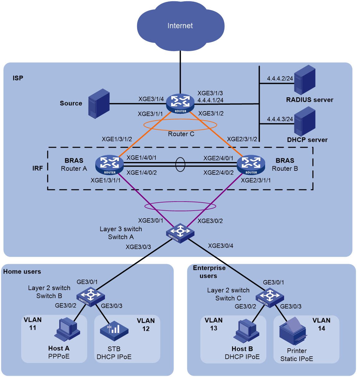
Table 1 Interfaces and IP address assignment
Device | Interface | IP address | Device | Interface | IP address |
RADIUS server |
| 4.4.4.2/24 | IRF fabric | RGG1 |
|
DHCP server |
| 4.4.4.3/24 |
| RGG1.1 |
|
Multicast source |
| 5.5.5.2/24 |
| RGG1.2 |
|
Router C | RGG1023 | 3.3.3.2/24 |
| RGG1023 | 3.3.3.1/24 |
XGE3/1/1 |
|
| XGE1/3/1/1 |
| |
XGE3/1/2 |
|
| XGE2/3/1/1 |
| |
XGE3/1/3 | 4.4.4.1/24 |
| XGE1/3/1/2 |
| |
XGE3/1/4 | 5.5.5.1/24 |
| XGE2/3/1/2 |
|
Table 2 User information
User | Access interface | Access method | Username/password | Rate limit | Data plan |
Host A | RGG1.1 | PPPoE | User@isp1/radius | 8 Mbps | 100 yuan per month |
STB | RGG1.1 | DHCP+IPoE | 78acc09f8592@iptv/123-iptv | 4 Mbps | 150 yuan per month |
Host B | RGG1.2 | DHCP+IPoE | 001b21a80949@isp2/radius | 10 Mbps | 800 yuan per year |
Printer | RGG1.2 | Static IPoE | 000c29a6b656@print/radius | 2 Mbps | No accounting |
Analysis
To meet the network requirements, you must perform the following tasks:
· IRF
¡ To avoid service interruption caused by single points of failure, configure a cross-chassis aggregate interface.
¡ To minimize the impact of IRF splitting, configure LACP MAD.
LACP MAD is required only for one aggregation group. The intermediate device used for LACP MAD must be from H3C and the installed software version must be able to identify and process LACPDUs with the ActiveID field. In this example, Switch A is used as an intermediate device.
· General
¡ To ensure bandwidth requirements of users, configure CAR settings on the RADIUS server.
¡ To improve the scalability in port usage and VLAN usage of the BRAS, enable QinQ (outer VLAN ID is service provider VLAN 101) on the Layer 3 switch (Switch A) of the ISP, and enable VLAN termination on a subinterface (GigabitEthernet 3/1/1.1 on the BRAS) for user access on the BRAS.
¡ For the DHCP relay agent to notify the DHCP server to release the IP address when a user goes offline, enable recording client information in relay entries on the DHCP relay agent. When a PPPoE user goes offline, the DHCP relay agent can find a matching relay entry and send a DHCP-RELEASE message to the DHCP server.
· PPPoE
¡ When DHCP works with PPPoE, you do not need to execute the dhcp select relay proxy command if the remote-server command is executed in DHCP relay address pool view.
¡ To use a DHCP address pool to assign IP addresses to users, execute the gateway-list export-route command to configure gateway addresses for IPCP negotiation. Do not configure an IP address for a VT interface for IPCP negotiation.
¡ In this example, the subnet address for PPPoE users is 1.1.1.0/24, and the ISP domain is domain isp1.
· IPoE
¡ To allow abnormally logged out DHCP users to come online again through packet initiation, enable unclassified-IPv4 packet initiation or ARP packet initiation.
¡ For the BRAS to delete the IPoE session of a user that goes offline unexpectedly (for example, by removing the network cable), configure online detection for IPv4 IPoE users. By default, the BRAS uses the ARP request packet to detect IPv4 users. It performs a maximum of five detection attempts after the first detection failure. The detection timer is 120 seconds.
¡ In this example, the subnet address for IPoE users is 2.2.2.0/24, and the ISP domains used by the STB, Host B, and the printer are domains iptv, isp2, and print, respectively.
· Multicast
¡ To lessen the burden on the Layer 3 multicast device (the IRF fabric in this example), configure a multicast VLAN on Switch C.
¡ This example uses the sub-VLAN-based multicast VLAN.
Configuration restrictions and guidelines
When you configure BRAS services, follow these restrictions and guidelines:
· IRF
After the IRF mode is enabled, the CEPC cards cannot be used.
· General
¡ If you configure an authorization IP address pool both in ISP domain view and on the RADIUS server, the authorization IP address pool configured on the RADIUS server is used. In this configuration example, all authorization attributes are configured in ISP domain view.
¡ In this configuration example, the DHCP server is emulated by an H3C device. As a best practice, use a dedicated DHCP server.
· IPoE
¡ After IPoE is enabled on an interface, the BRAS discards packets from users by default. You must enable individual users on the interface to trigger IPoE session establishment.
¡ The usernames and passwords configured for dynamic individual users must be the same as those configured on the RADIUS server. By default, a DHCPv4 user uses the source MAC address in packets as the username and uses vlan as the password.
¡ Online detection can use ARP or ICMP requests, but not both, to detect IPv4 individual users. If IPv4 individual users and the interface are in different subnets, only ICMP request packets can be used for detection.
¡ If the BRAS acts as a DHCP relay agent, you must execute the dhcp select relay proxy command on the access interface (Route-Aggregation1.2 in this example).
· Multicast
¡ As a best practice, do not configure a multicast VLAN on a device that is configured with multicast routing.
¡ A multicast VLAN must be an existing VLAN.
¡ The VLANs to be configured as sub-VLANs of a multicast VLAN must already exist and cannot be multicast VLANs or sub-VLANs of any other multicast VLAN.
¡ When the STB service is specified for an ISP domain, the multicast feature of the access module is enabled to improve the performance of the multicast module.
Procedures
Setting up an IRF fabric
Configuring Router A
# Assign member ID 1 to Router A.
<RouterA> system-view
[RouterA] irf member 1
# Save the configuration.
[RouterA] save
# Connect Router A and Router B as shown in Figure 2.
# Enable IRF mode.
[RouterA] chassis convert mode irf
The Router will switch to IRF mode and reboot.
You are recommended to save the current running configuration and specify the configuration file for the next startup. Continue? [Y/N]:y
Do you want to convert the content of the next startup configuration file cfa0:/irf.cfg to make it available in stack mode? [Y/N]:y
Now rebooting, please wait...
# Shut down Ten-GigabitEthernet 1/4/0/1 and Ten-GigabitEthernet 1/4/0/2.
<RouterA> system-view
[RouterA] interface ten-gigabitethernet 1/4/0/1
[RouterA-Ten-GigabitEthernet1/4/0/1] shutdown
[RouterA-Ten-GigabitEthernet1/4/0/1] quit
[RouterA] interface ten-gigabitethernet 1/4/0/2
[RouterA-Ten-GigabitEthernet1/4/0/2] shutdown
[RouterA-Ten-GigabitEthernet1/4/0/2] quit
# Enter the view of IRF port 2, and bind Ten-GigabitEthernet 1/4/0/1 and Ten-GigabitEthernet 1/4/0/2 to IRF-port 2
[RouterA] irf-port 2
[RouterA-irf-port2] port group interface ten-gigabitethernet 1/4/0/1
[RouterA-irf-port2] port group interface ten-gigabitethernet 1/4/0/2
[RouterA-irf-port2] quit
# Bring up Ten-GigabitEthernet 1/4/0/1 and Ten-GigabitEthernet 1/4/0/2.
[RouterA] interface ten-gigabitethernet 1/4/0/1
[RouterA-Ten-GigabitEthernet1/4/0/1] undo shutdown
[RouterA-Ten-GigabitEthernet1/4/0/1] quit
[RouterA] interface ten-gigabitethernet 1/4/0/2
[RouterA-Ten-GigabitEthernet1/4/0/2] undo shutdown
[RouterA-Ten-GigabitEthernet1/4/0/2] quit
# Activate the IRF port settings.
[RouterA] irf-port-configuration active
Configuring Router B
# Assign member ID 2 to Router B.
<RouterB> system-view
[RouterB] irf member 2
# Save the configuration.
[RouterB] save
# Connect Router A and Router B as shown in Figure 2.
# Enable IRF mode.
[RouterB] chassis convert mode irf
The Router will switch to IRF mode and reboot.
You are recommended to save the current running configuration and specify the configuration file for the next startup. Continue? [Y/N]:y
Do you want to convert the content of the next startup configuration file cfa0:/irf.cfg to make it available in stack mode? [Y/N]:y
Now rebooting, please wait...
# Shut down Ten-GigabitEthernet 2/4/0/1 and Ten-GigabitEthernet 2/4/0/2.
<RouterB> system-view
[RouterB] interface ten-gigabitethernet 2/4/0/1
[RouterB-Ten-GigabitEthernet2/4/0/1] shutdown
[RouterB-Ten-GigabitEthernet2/4/0/1] quit
[RouterB] interface ten-gigabitethernet 2/4/0/2
[RouterB-Ten-GigabitEthernet2/4/0/2] shutdown
[RouterB-Ten-GigabitEthernet2/4/0/2] quit
# Enter the view of IRF port 1, and bind Ten-GigabitEthernet 2/4/0/1 and Ten-GigabitEthernet 2/4/0/2 to IRF-port 1
[RouterB] irf-port 1
[RouterB-irf-port1] port group interface ten-gigabitethernet 2/4/0/1
[RouterB-irf-port1] port group interface ten-gigabitethernet 2/4/0/2
[RouterB-irf-port1] quit
# Bring up Ten-GigabitEthernet 2/4/0/1 and Ten-GigabitEthernet 2/4/0/2.
[RouterB] interface ten-gigabitethernet 2/4/0/1
[RouterB-Ten-GigabitEthernet2/4/0/1] undo shutdown
[RouterB-Ten-GigabitEthernet2/4/0/1] quit
[RouterB] interface ten-gigabitethernet 2/4/0/2
[RouterB-Ten-GigabitEthernet2/4/0/2] undo shutdown
[RouterB-Ten-GigabitEthernet2/4/0/2] quit
# Activate the IRF port settings.
[RouterB] irf-port-configuration active
# Reboot Router B.
<RouterB> reboot
Configuring LACP MAD on the IRF fabric
# Create a dynamic aggregation group to connect to Switch A, and enable LACP MAD on the aggregate interface.
<IRF> system-view
[IRF] interface route-aggregation 1
[IRF-Route-Aggregation1] link-aggregation mode dynamic
[IRF-Route-Aggregation1] mad enable
You need to assign a domain ID (range: 0-4294967295)
[Current domain is: 0]:
The assigned domain ID is: 0
MAD LACP only enable on dynamic aggregation interface.
[IRF-Route-Aggregation1] quit
# Assign Ten-GigabitEthernet 1/3/1/1 and Ten-GigabitEthernet 2/3/1/1 to the aggregation group.
[IRF] interface ten-gigabitethernet 1/3/1/1
[IRF-Ten-GigabitEthernet1/3/1/1] port link-aggregation group 1
[IRF-Ten-GigabitEthernet1/3/1/1] quit
[IRF] interface ten-gigabitethernet 2/3/1/1
[IRF-Ten-GigabitEthernet2/3/1/1] port link-aggregation group 1
[IRF-Ten-GigabitEthernet2/3/1/1] quit
Configuring downlink settings for the IRF fabric on Switch A
# Create a dynamic aggregation group used to connect to the IRF fabric and used for LACP MAD.
<SwitchA> system-view
[SwitchA] interface bridge-aggregation 1
[SwitchA-Bridge-Aggregation1] link-aggregation mode dynamic
[SwitchA-Bridge-Aggregation1] quit
# Assign Ten-GigabitEthernet 3/0/1 and Ten-GigabitEthernet 3/0/2 to the aggregation group.
[SwitchA] interface ten-gigabitethernet 3/0/1
[SwitchA-Ten-GigabitEthernet3/0/1] port link-aggregation group 1
[SwitchA-Ten-GigabitEthernet3/0/1] quit
[SwitchA] interface ten-gigabitethernet 3/0/2
[SwitchA-Ten-GigabitEthernet3/0/2] port link-aggregation group 1
[SwitchA-Ten-GigabitEthernet3/0/2] quit
Configuring uplink settings for the IRF fabric
1. Configure the IRF fabric
# Create an aggregation group used to connect to Router C.
[IRF] interface route-aggregation 1023
[IRF-Route-Aggregation1023] quit
# Assign Ten-GigabitEthernet 1/3/1/2 and Ten-GigabitEthernet 2/3/1/2 to the aggregation group.
[IRF] interface ten-gigabitethernet 1/3/1/2
[IRF-Ten-GigabitEthernet1/3/1/2] port link-aggregation group 1023
[IRF-Ten-GigabitEthernet1/3/1/2] quit
[IRF] interface ten-gigabitethernet 2/3/1/2
[IRF-Ten-GigabitEthernet2/3/1/2] port link-aggregation group 1023
[IRF-Ten-GigabitEthernet2/3/1/2] quit
# Assign an IP address to the aggregate interface.
[IRF] interface Route-aggregation 1023
[IRF-Route-Aggregation1023] ip address 3.3.3.1 24
[IRF-Route-Aggregation1023] quit
# Configure OSPF.
[IRF] ospf
[IRF-ospf-1] import-route direct
[IRF-ospf-1] area 0
[IRF-ospf-1-area-0.0.0.0] network 3.3.3.0 0.0.0.255
[IRF-ospf-1-area-0.0.0.0] quit
[IRF-ospf-1] quit
2. Configure Router C:
# Create an aggregation group used to connect to the IRF fabric.
<RouterC> system-view
[RouterC] interface route-aggregation 1023
[RouterC-Route-Aggregation1023] quit
# Assign Ten-GigabitEthernet 3/1/1 and Ten-GigabitEthernet 3/1/2 to the aggregation group.
[RouterC] interface ten-gigabitethernet 3/1/1
[RouterC-Ten-GigabitEthernet3/1/1] port link-aggregation group 1023
[RouterC-Ten-GigabitEthernet3/1/1] quit
[RouterC] interface ten-gigabitethernet 3/1/2
[RouterC-Ten-GigabitEthernet3/1/2] port link-aggregation group 1023
[RouterC-Ten-GigabitEthernet3/1/2] quit
# Assign an IP address to the aggregate interface.
[RouterC] interface route-aggregation 1023
[RouterC-Route-Aggregation1023] ip address 3.3.3.2 24
[RouterC-Route-Aggregation1023] quit
# Assign an IP address to Ten-GigabitEthernet 3/1/3.
[RouterC] interface ten-gigabitethernet 3/1/3
[RouterC-Ten-GigabitEthernet3/1/3] ip address 4.4.4.1 24
[RouterC-Ten-GigabitEthernet3/1/3] quit
# Assign an IP address to Ten-GigabitEthernet 3/1/4.
[RouterC] interface ten-gigabitethernet 3/1/4
[RouterC-Ten-GigabitEthernet3/1/4] ip address 5.5.5.1 24
[RouterC-Ten-GigabitEthernet3/1/4] quit
# Configure OSPF.
[RouterC] ospf
[RouterC-ospf-1] import-route direct
[RouterC-ospf-1] area 0
[RouterC-ospf-1-area-0.0.0.0] network 3.3.3.0 0.0.0.255
[RouterC-ospf-1-area-0.0.0.0] quit
[RouterC-ospf-1] quit
# Configure a static route to IPoE users.
[RouterC] ip route-static 2.2.2.0 24 3.3.3.1
Verifying the configuration
# Verify that the IRF fabric has been successfully set up.
[IRF] display irf
MemberID Slot Role Priority CPU-Mac Description
*+1 0 Master 1 0210-fc01-0000 ---
2 0 Standby 1 0210-fc02-0000 ---
--------------------------------------------------
* indicates the device is the master.
+ indicates the device through which the user logs in.
The Bridge MAC of the IRF is: 3822-d60f-2800
Auto upgrade : yes
Mac persistent : always
Domain ID : 0
Auto merge : no
The output shows that the IRF fabric has been successfully set up.
Configuring the BRAS
Configuring the RADIUS server
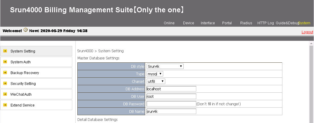
The following configuration uses Srun Billing Management Suite 4.1.0 of Srun Software as an example to illustrate the operation procedure for adding a PPPoE user. The operation procedure for adding an IPoE user is similar.
1. Open a web browser, enter http://4.4.4.2:8081 to log in to the server to add a access device and configure RADIUS attributes.
Figure 3 Login page
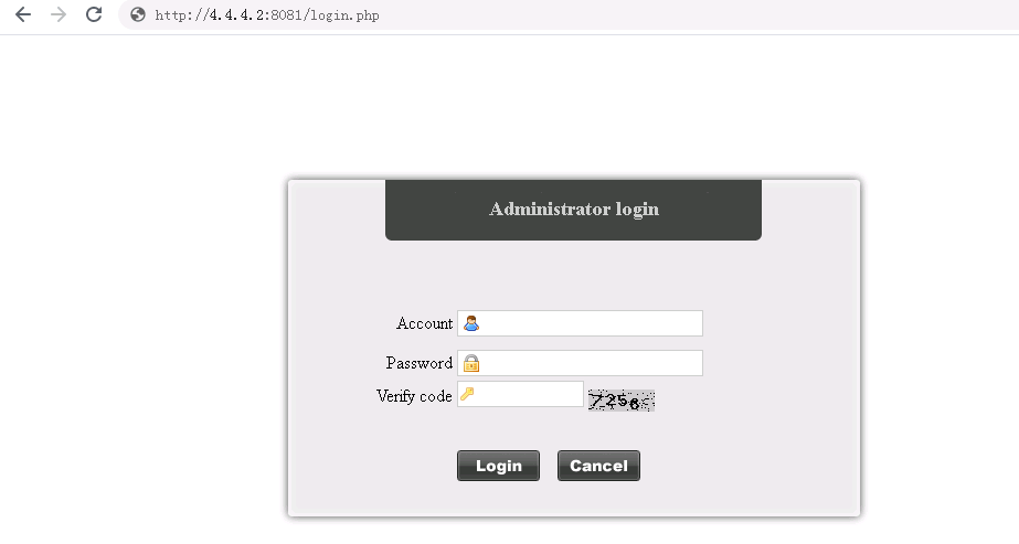
2. Enter the username, password, and verification code, and click Login.
Figure 4 Login page
3. Click Device > Add Device.
Figure 5 Adding a device
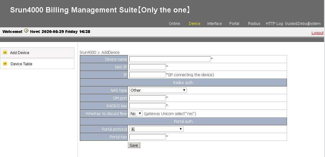
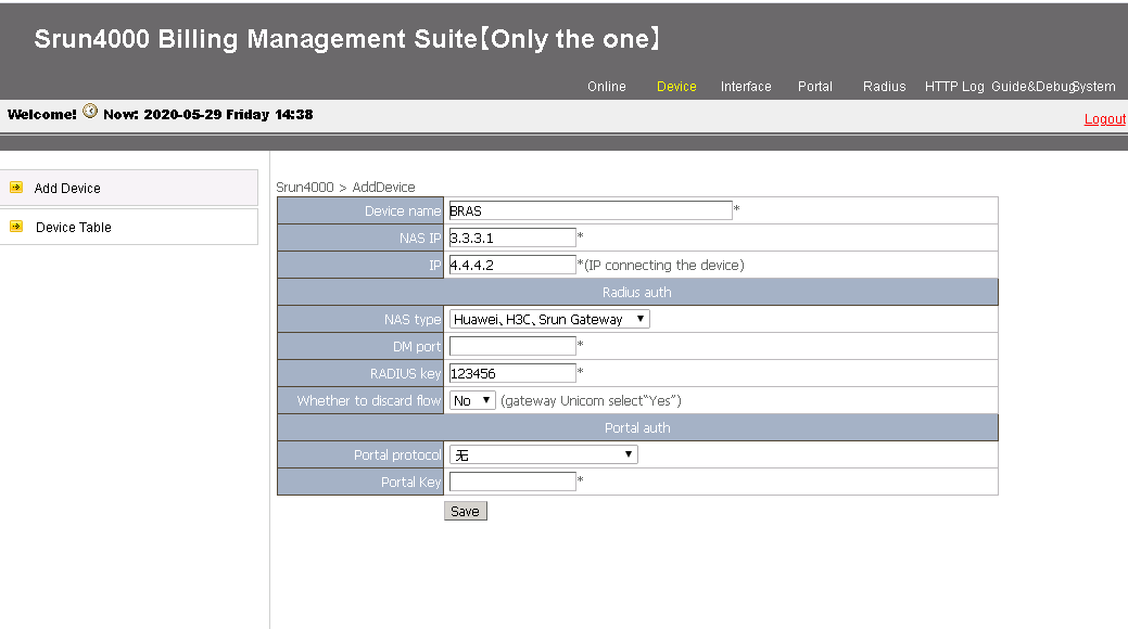
4. Configure the following parameters and then click Save to add a device:
¡ Device name—Enter the device name of the NAS (the device name is BRAS in this example).
¡ NAS IP—Enter the IP address of the NAS (3.3.3.1, the IP address of the BRAS in this example).
¡ IP—Enter the IP address of the host where the Srun software is installed (4.4.4.2 in this example).
¡ NAS type—Specify the NAS type.
¡ RADIUS key—Enter the key used for communication between the NAS and the RADIUS server (123456 in this example).
Figure 6 Adding a device
5. Click Radius > Add RADIUS Attributes to add a rate limit attribute.
6. Click Radius Trust Setting, and click Generate on the upper right corner to generate trust settings.
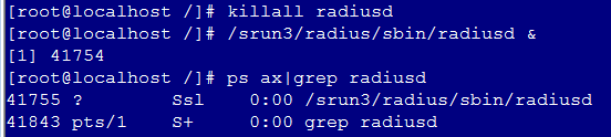
7. Re-enable the RADIUS service for the trust settings to take effect.
To re-enable the RADIUS service, access the CLI of the Srun server, execute the killall radiusd command to disable the RADIUS service and then execute the /srun3/radius/sbin/radiusd & command to enable the RADIUS service.
Figure 7 Re-enabling the RADIUS service
8. Open a web browser, enter http://4.4.4.2:8080 to log in to the server to configure policies and users.
9. Configure a control policy:
a. Click Strategy > Control, and click Add.
b. Enter the policy name Rate-limit 8M.
c. Select the added attribute in step 5 for the self-defined attributes field.
d. Use default settings for other fields, and click Save.
10. Configure a billing policy:
a. Click Strategy > Billing, and click Add.
b. Enter 100 yuan each month in the Title field.
c. Use default settings for other fields, and click Save.
11. Configure a product policy:
a. Click Strategy > Product, and click Add.
b. Enter PPPoE user policy in the Product Name field.
c. Select 100 yuan each month for the Billing Strategy field.
d. Select Rate-limit 8M for the Control Strategy field.
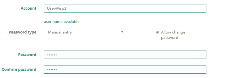
12. Add user Host A:
a. Click Account > Add.
b. Enter the username and password of Host A in the Account field.
c. Select the group pppoe(ID:16), select Pppoe, and enter 500 in the text box.
d. Use default settings for other fields, and click save.
Figure 8 Adding a user

Configuring the DHCP server
1. Enable DHCP.
<DHCP> system-view
[DHCP] dhcp enable
2. Configure a DHCP address pool for PPPoE users:
# Create a DHCP address pool named pool1 and enter its view.
[DHCP] dhcp server ip-pool pool1
# Specify the subnet for dynamic allocation, specify a gateway address, and specify a DNS server address for the DHCP address pool.
[DHCP-dhcp-pool-pool1] network 1.1.1.0 24
[DHCP-dhcp-pool-pool1] gateway-list 1.1.1.1
[DHCP-dhcp-pool-pool1] dns-list 8.8.8.8
# Exclude IP address 1.1.1.1 from dynamic allocation.
[DHCP-dhcp-pool-pool1] forbidden-ip 1.1.1.1
[DHCP-dhcp-pool-pool1] quit
3. Configure a DHCP address pool for IPoE users:
# Create a DHCP address pool named pool2 and enter its view.
[DHCP] dhcp server ip-pool pool2
# Specify the subnet for dynamic allocation, specify a gateway address, and specify a DNS server address for the DHCP address pool.
[DHCP-dhcp-pool-pool2] network 2.2.2.0 24
[DHCP-dhcp-pool-pool2] gateway-list 2.2.2.1
[DHCP-dhcp-pool-pool2] dns-list 8.8.8.8
# Exclude IP addresses 2.2.2.1 and 2.2.2.252 from dynamic allocation.
[DHCP-dhcp-pool-pool2] forbidden-ip 2.2.2.1
[DHCP-dhcp-pool-pool2] forbidden-ip 2.2.2.252
[DHCP-dhcp-pool-pool2] quit
4. Configure static routes to the BRAS.
[DHCP] ip route-static 1.1.1.0 24 4.4.4.1
[DHCP] ip route-static 2.2.2.0 24 4.4.4.1
Configuring common settings for PPPoE and IPoE
1. Configure a RADIUS scheme:
# Create a RADIUS scheme named rs1.
[BRAS] radius scheme rs1
# Specify the primary authentication server and primary accounting server, and set the shared keys to 123456 in plaintext form for authentication and accounting.
[BRAS-radius-rs1] primary authentication 4.4.4.2
[BRAS-radius-rs1] primary accounting 4.4.4.2
[BRAS-radius-rs1] key authentication simple 123456
[BRAS-radius-rs1] key accounting simple 123456
# Specify the IP address of Layer 3 aggregate interface 1023 as the source IP address for outgoing RADIUS packets.
[BRAS-radius-rs1] nas-ip 3.3.3.1
[BRAS-radius-rs1] quit
# Specify the DAC as 4.4.4.2. Set the shared key to 123456 in plaintext form for secure communication between the BRAS and DAC.
[BRAS] radius dynamic-author server
[BRAS-radius-da-server] client ip 4.4.4.2 key simple 123456
[BRAS-radius-da-server] quit
2. Configure the DHCP relay agent:
# Enable DHCP.
[BRAS] dhcp enable
# Enable recording client information in relay entries.
[BRAS] dhcp relay client-information record
# Disable the DHCP relay agent to periodically refresh dynamic relay entries.
[BRAS] undo dhcp relay client-information refresh enable
# Create a DHCP relay address pool named pool1 for PPPoE users, and configure the address pool to assign IP addresses and other configuration parameters to PPPoE users.
[BRAS] dhcp server ip-pool pool1
[BRAS-dhcp-pool-pool1] gateway-list 1.1.1.1 export-route
[BRAS-dhcp-pool-pool1] remote-server 4.4.4.3
[BRAS-dhcp-pool-pool1] quit
# Create a DHCP relay address pool named pool2 for IPoE users, and configure the address pool to assign IP addresses and other configuration parameters to IPoE users.
[BRAS] dhcp server ip-pool pool2
[BRAS-dhcp-pool-pool2] gateway-list 2.2.2.1 export-route
[BRAS-dhcp-pool-pool2] remote-server 4.4.4.3
[BRAS-dhcp-pool-pool2] quit
Configuring authentication domains
· Configure an authentication domain for PPPoE users
# Create an ISP domain named isp1 and enter ISP domain view.
[BRAS] domain name isp1
# Configure the ISP domain to use RADIUS scheme rs1 for authentication, authorization, and accounting.
[BRAS-isp-isp1] authentication ppp radius-scheme rs1
[BRAS-isp-isp1] authorization ppp radius-scheme rs1
[BRAS-isp-isp1] accounting ppp radius-scheme rs1
# Configure address pool pool1 as the authorization address pool for the ISP domain.
[BRAS-isp-isp1] authorization-attribute ip-pool pool1
[BRAS-isp-isp1] quit
· Configure an authentication domain for IPoE users
# Create an ISP domain named iptv for the STB and enter ISP domain view.
[BRAS] domain name iptv
# Configure the ISP domain to use RADIUS scheme rs1 for authentication, authorization, and accounting.
[BRAS-isp-iptv] authentication ipoe radius-scheme rs1
[BRAS-isp-iptv] authorization ipoe radius-scheme rs1
[BRAS-isp-iptv] accounting ipoe radius-scheme rs1
# Configure address pool pool2 as the authorization address pool for the ISP domain.
[BRAS-isp-iptv] authorization-attribute ip-pool pool2
[BRAS-isp-iptv] quit
# Create an ISP domain named isp2 for Host B and enter ISP domain view.
[BRAS] domain name isp2
# Configure the ISP domain to use RADIUS scheme rs1 for authentication, authorization, and accounting.
[BRAS-isp-isp2] authentication ipoe radius-scheme rs1
[BRAS-isp-isp2] authorization ipoe radius-scheme rs1
[BRAS-isp-isp2] accounting ipoe radius-scheme rs1
# Configure address pool pool2 as the authorization address pool for the ISP domain.
[BRAS-isp-isp2] authorization-attribute ip-pool pool2
[BRAS-isp-isp2] quit
# Create an ISP domain named print for the printer and enter ISP domain view.
[BRAS] domain name print
# Configure the ISP domain to use RADIUS scheme rs1 for authentication and authorization.
[BRAS-isp-print] authentication ipoe radius-scheme rs1
[BRAS-isp-print] authorization ipoe radius-scheme rs1
[BRAS-isp-print] accounting ipoe none
[BRAS-isp-print] quit
Configuring PPPoE access for home user Host A
· Configure a VT template:
# Create a VT interface, enable PPP accounting, and set the authentication mode to CHAP on the interface.
[BRAS] interface virtual-template 1
[BRAS-Virtual-Template1] ppp account-statistics enable
[BRAS-Virtual-Template1] ppp authentication-mode chap domain isp1
[BRAS-Virtual-Template1] quit
# Create a Layer 3 aggregate subinterface and enter its view.
[BRAS] interface route-aggregation 1.1
# Enable the PPPoE server on the Layer 3 aggregate subinterface, and bind it to the VT interface.
[BRAS-Route-Aggregation1.1] pppoe-server bind virtual-template 1
[BRAS-Route-Aggregation1.1] quit
· Configure unambiguous user QinQ termination on the Layer 3 aggregate subinterface by specifying the outermost two layers of VLAN IDs.
[BRAS] interface route-aggregation 1.1
[BRAS-Route-Aggregation1.1] user-vlan dot1q vid 101 second-dot1q 11
[BRAS-Route-Aggregation1.1] quit
Configure IPoE access for the STB
· Configure DHCPv4 packet initiation:
# Create a Layer 3 aggregate subinterface and enter its view.
[BRAS] interface route-aggregation 1.1
# Enable IPoE and configure the Layer 2 access mode on the subinterface.
[BRAS–Route-Aggregation1.1] ip subscriber l2-connected enable
# Enable DHCPv4 packet initiation on the subinterface.
[BRAS–Route-Aggregation1.1] ip subscriber initiator dhcp enable
# Configure DHCPv4 Option 60 as the trusted option on the subinterface.
[BRAS–Route-Aggregation1.1] ip subscriber trust option60
# Configure ISP domain iptv as the trusted ISP domain.
[BRAS–Route-Aggregation1.1] ip subscriber dhcp option60 match iptv
# Configure the source MAC address as the authentication username. By default, the source MAC address is used as the authentication username.
[BRAS–Route-Aggregation1.1] ip subscriber dhcp username include source-mac
# Configure all information in Option 60 as the authentication password.
[BRAS–Route-Aggregation1.1] ip subscriber dhcp password option60
# Enable the DHCP relay agent on the subinterface.
[BRAS–Route-Aggregation1.1] dhcp select relay proxy
· Configure unclassified-IPv4 packet initiation:
# Enable unclassified-IPv4 packet initiation.
[BRAS–Route-Aggregation1.1] ip subscriber initiator unclassified-ip enable matching-user
# Configure the plaintext authentication password 123-iptv.
[BRAS–Route-Aggregation1.1] ip subscriber password plaintext 123-iptv
· Configure VLAN termination:
# Configure unambiguous user QinQ termination on the Layer 3 aggregate subinterface by specifying the outermost two layers of VLAN IDs.
[BRAS-Route-Aggregation1.1] user-vlan dot1q vid 101 second-dot1q 12
# Enable the subinterface to transmit broadcasts and multicasts.
[BRAS-Route-Aggregation1.1] vlan-termination broadcast enable
# Enable local proxy ARP and proxy ARP on the subinterface.
[BRAS-Route-Aggregation1.1] local-proxy-arp enable
[BRAS-Route-Aggregation1.1] proxy-arp enable
[BRAS-Route-Aggregation1.1] quit
Configure IPoE access for enterprise users
· Configure DHCPv4 packet initiation:
# Create a Layer 3 aggregate subinterface and enter its view.
[BRAS] interface route-aggregation 1.2
# Enable IPoE and configure the Layer 2 access mode on the subinterface.
[BRAS–Route-Aggregation1.2] ip subscriber l2-connected enable
# Enable DHCPv4 packet initiation on the subinterface.
[BRAS–Route-Aggregation1.2] ip subscriber initiator dhcp enable
# Configure ISP domain isp2 as the trusted ISP domain.
[BRAS–Route-Aggregation1.2] ip subscriber dhcp domain isp2
# Configure the source MAC address as the authentication username. By default, the source MAC address is used as the authentication username.
[BRAS–Route-Aggregation1.2] ip subscriber dhcp username include source-mac
# Configure the plaintext authentication password radius.
[BRAS–Route-Aggregation1.2] ip subscriber password plaintext radius
# Enable the DHCP relay agent on the subinterface.
[BRAS–Route-Aggregation1.2] dhcp select relay proxy
· Configure unclassified-IPv4 packet initiation:
# Enable unclassified-IPv4 packet initiation.
[BRAS–Route-Aggregation1.2] ip subscriber initiator unclassified-ip enable matching-user
# Configure the plaintext authentication password radius
[BRAS–Route-Aggregation1.2] ip subscriber password plaintext radius
· Configure IPoE for the static user:
# Configure an IPv4 IPoE static session with an IP address of 2.2.2.252 and an ISP domain of print on Layer 3 aggregate subinterface 1.2.
[BRAS–Route-Aggregation1.2] ip subscriber initiator unclassified-ip enable matching-user
· Configure VLAN termination:
# Configure ambiguous user VLAN Dot1q termination on the subinterface.
[BRAS-Route-Aggregation1.2] user-vlan dot1q vid 13 14
# Enable the subinterface to transmit broadcasts and multicasts.
[BRAS-Route-Aggregation1.2] vlan-termination broadcast enable
# Enable local proxy ARP and proxy ARP on the subinterface.
[BRAS-Route-Aggregation1.2] local-proxy-arp enable
[BRAS-Route-Aggregation1.2] proxy-arp enable
[BRAS-Route-Aggregation1.2] quit
Configuring Switch A
# Create a service provider VLAN numbered 101.
<SwitchA> system-view
[SwitchA] vlan 101
[SwitchA-vlan101] quit
# Create customer VLANs numbered 13 and 14.
[SwitchC] vlan 13 to 14
# Configure Layer 2 aggregate interface 1 as a trunk port, and assign it to VLAN 13, VLAN 14, and VLAN 101.
[SwitchA] interface bridge-aggregation 1
[SwitchA-Bridge-Aggregation1] port link-type trunk
[SwitchA-Bridge-Aggregation1] port trunk permit vlan 13 to 14 101
[SwitchA-Bridge-Aggregation1] quit
# For Ten-GigabitEthernet 3/0/1 and Ten-GigabitEthernet 3/0/2 to become Select member ports of the Layer 2 aggregate interface, configure them as trunk ports, and assign them to VLAN 13, VLAN 14, and VLAN 101.
[SwitchA] interface range ten-gigabitethernet 3/0/1 to ten-gigabitethernet 3/0/2
[SwitchA-if-range] port link-type trunk
[SwitchA-if-range] port trunk permit vlan 13 to 14 101
[SwitchA-if-range] quit
# Configure Ten-GigabitEthernet 3/0/3 as a trunk port, and assign it to VLAN 101.
[SwitchA] interface ten-gigabitethernet 3/0/3
[SwitchA-Ten-GigabitEthernet3/0/3] port link-type trunk
[SwitchA-Ten-GigabitEthernet3/0/3] port trunk permit vlan 101
# Set the PVID for Ten-GigabitEthernet 3/0/3 to VLAN 101, and enable QinQ on it.
[SwitchA-Ten-GigabitEthernet3/0/3] port trunk pvid vlan 101
[SwitchA-Ten-GigabitEthernet3/0/3] qinq enable
[SwitchA-Ten-GigabitEthernet3/0/3] quit
# Configure Ten-GigabitEthernet 3/0/4 as a trunk port, and assign it to VLAN 13 and VLAN 14.
[SwitchA] interface ten-gigabitethernet 3/0/4
[SwitchA-Ten-GigabitEthernet3/0/4] port link-type trunk
[SwitchA-Ten-GigabitEthernet3/0/4] port trunk permit vlan 13 14
[SwitchA-Ten-GigabitEthernet3/0/4] quit
Configuring Switch B
# Create customer VLANs numbered 11 and 12.
[SwitchB] vlan 11 to 12
# Configure GigabitEthernet 3/0/1 as a trunk port, and assign it to VLAN 11 and VLAN 12.
[SwitchB] interface gigabitethernet 3/0/1
[SwitchB-GigabitEthernet3/0/1] port link-type trunk
[SwitchB-GigabitEthernet3/0/1] port trunk permit vlan 11 12
[SwitchB-GigabitEthernet3/0/1] quit
# Assign GigabitEthernet 3/0/2 to VLAN 11.
[SwitchB] interface gigabitethernet 3/0/2
[SwitchB-GigabitEthernet3/0/2] port access vlan 11
[SwitchB-GigabitEthernet3/0/2] quit
# Assign GigabitEthernet 3/0/3 to VLAN 12.
[SwitchB] interface gigabitethernet 3/0/3
[SwitchB-GigabitEthernet3/0/3] port access vlan 12
[SwitchB-GigabitEthernet3/0/3] quit
Configuring Switch C
# Create customer VLANs numbered 13 and 14.
[SwitchC] vlan 13 to 14
# Configure GigabitEthernet 3/0/1 as a trunk port, and assign it to VLAN 13 and VLAN 14.
[SwitchC] interface gigabitethernet 3/0/1
[SwitchC-GigabitEthernet3/0/1] port link-type trunk
[SwitchC-GigabitEthernet3/0/1] port trunk permit vlan 13 14
[SwitchC-GigabitEthernet3/0/1] quit
# Assign GigabitEthernet 3/0/2 to VLAN 13.
[SwitchC] interface gigabitethernet 3/0/2
[SwitchC-GigabitEthernet3/0/2] port access vlan 13
[SwitchC-GigabitEthernet3/0/2] quit
# Assign GigabitEthernet 3/0/3 to VLAN 14.
[SwitchC] interface gigabitethernet 3/0/3
[SwitchC-GigabitEthernet3/0/3] port access vlan 14
[SwitchC-GigabitEthernet3/0/3] quit
Verifying the basic BRAS configuration
· Verify the configuration by Host A:
# Verify that the user at Host A can use username User1@isp1 and password pass1 to dial in to the BRAS to access the Internet.
# Verify that Host A has obtained an IP address through DHCP.
[BRAS] display dhcp relay client-information
Total number of client-information items: 1
Total number of dynamic items: 1
Total number of temporary items: 0
IP address MAC address Type Interface VPN name
1.1.1.2 e839-3563-fb21 Dynamic BAS0 N/A
# Display detailed information about user User1@isp1.
[BRAS] display ppp access-user username User@isp1 verbose
Basic:
Interface: BAS0
PPP index: 0x140000105
User ID: 0x20000001
Username: User@isp1
Domain: isp1
Access interface: RAGG1.1
Service-VLAN/Customer-VLAN: 101/11
VXLAN ID: -
MAC address: e839-3563-fb21
IP address: 1.1.1.2
Primary DNS server: 8.8.8.8
IPv6 address: -
IPv6 PD prefix: -
IPv6 ND prefix: -
User address type: N/A
VPN instance: -
Access type: PPPoE
Authentication type: CHAP
PPPoE:
Session ID: 1
AAA:
Authentication state: Authenticated
Authorization state: Authorized
Realtime accounting switch: Open
Realtime accounting interval: 720s
Login time: 2016-03-21 12:06:40:886
Accounting start time: 2016-03-21 12:06:41:614
Online time(hh:mm:ss): 00:01:45
Accounting state: Accounting
Acct start-fail action: Online
Acct update-fail action: Online
Acct quota-out action: Offline
Dual-stack accounting mode: Merge
Idle cut: 0 sec 0 byte, direction: Both
Session timeout: -
Time remained: -
Traffic quota: -
Traffic remained: -
Redirect WebURL: -
ITA policy name: -
MRU: 1480 bytes
IPv4 MTU: 1480 bytes
IPv6 MTU: 1480 bytes
Subscriber ID: -
ACL&QoS:
User profile: -
Session group profile: -
User group acl: -
Inbound CAR: CIR 8000 kbps PIR 8000 kbps CBS - (active)
Outbound CAR: CIR 8000 kbps PIR 8000 kbps CBS - (active)
User inbound priority: -
User outbound priority: -
Flow Statistic:
IPv4 uplink packets/bytes: 508/53292
IPv4 downlink packets/bytes: 285/26198
IPv6 uplink packets/bytes: 0/0
IPv6 downlink packets/bytes: 0/0
The output shows that Host A has successfully dialed in to the BRAS and obtained IP address 1.1.1.2.
· Verify the configuration by the STB:
# Verify that the STB can pass IPoE authentication after being powered on.
# Verify that Host A has obtained an IP address through DHCP.
[BRAS] display dhcp relay client-information
Total number of client-information items: 1
Total number of dynamic items: 1
Total number of temporary items: 0
IP address MAC address Type Interface VPN name
2.2.2.2 78ac-c09f-8592 Dynamic RAGG1.1 N/A
# Display detailed information about the STB user.
[BRAS] display ip subscriber session username 001b21a80949 verbose
Basic:
Description : -
Username : 78acc09f8592@iptv
Domain : iptv
VPN instance : N/A
IP address : 2.2.2.2
User address type : N/A
MAC address : 78ac-c09f-8592
Service-VLAN/Customer-VLAN : 101/12
Access interface : RAGG1.1
User ID : 0x38080003
VPI/VCI(for ATM) : -/-
VSI Index : -
VSI link ID : -
VXLAN ID : -
DNS servers : 8.8.8.8
IPv6 DNS servers : N/A
DHCP lease : 86400 sec
DHCP remain lease : N/A
Access time : Mar 21 13:38:02 2016
Online time(hh:mm:ss) : 00:19:36
Service node : Chassis 1 Slot 3 CPU 0
Authentication type : Bind
IPv4 access type : DHCP
IPv4 detect state : Detecting
State : Online
AAA:
ITA policy name : N/A
IP pool : pool2
IPv6 pool : N/A
IPv6 nd preifx pool : N/A
Primary DNS server : N/A
Secondary DNS server : N/A
Primary IPv6 DNS server : N/A
Secondary IPv6 DNS server : N/A
Session idle cut : N/A
Session duration : N/A, remaining: N/A
Traffic quota : N/A
Traffic remained : N/A
Acct start-fail action : Online
Acct update-fail action : Online
Acct quota-out action : Offline
Dual-stack accounting mode : Merge
Max IPv4 multicast addresses: 4
IPv4 multicast address list : N/A
Max IPv6 multicast addresses: 4
IPv6 multicast address list : N/A
Accounting start time : Mar 21 13:38:02 2016
Subscriber ID : -
QoS:
User profile : N/A
Session group profile : N/A
User group ACL : N/A
Inbound CAR : CIR 4000kps PIR 4000kbps CBS N/A (active)
Outbound CAR : CIR 4000kbps PIR 4000kbps CBS N/A (active)
Inbound user priority : N/A
Outbound user priority : N/A
Flow statistic:
Uplink packets/bytes : 43/5179
Downlink packets/bytes : 0/0
IPv6 uplink packets/bytes : 0/0
IPv6 downlink packets/bytes : 0/0
· Verify the configuration by Host B:
# Verify that Host B can pass IPoE authentication after being powered on.
# Verify that Host B has obtained an IP address through DHCP.
[BRAS] display dhcp relay client-information
Total number of client-information items: 1
Total number of dynamic items: 1
Total number of temporary items: 0
IP address MAC address Type Interface VPN name
2.2.2.3 001b-21a8-0949 Dynamic RAGG1.2 N/A
# Display detailed information about Host B.
[BRAS] display ip subscriber session username 001b21a80949 verbose
Basic:
Description : -
Username : 001b21a80949@isp2
Domain : isp2
VPN instance : N/A
IP address : 2.2.2.3
User address type : N/A
MAC address : 001b-21a8-0949
Service-VLAN/Customer-VLAN : 13/-
Access interface : RAGG1.2
User ID : 0x38080002
VPI/VCI(for ATM) : -/-
VSI Index : -
VSI link ID : -
VXLAN ID : -
DNS servers : 8.8.8.8
IPv6 DNS servers : N/A
DHCP lease : 86400 sec
DHCP remain lease : N/A
Access time : Mar 21 13:38:02 2016
Online time(hh:mm:ss) : 00:19:36
Service node : Chassis 1 Slot 3 CPU 0
Authentication type : Bind
IPv4 access type : DHCP
IPv4 detect state : Detecting
State : Online
AAA:
ITA policy name : N/A
IP pool : pool2
IPv6 pool : N/A
IPv6 nd preifx pool : N/A
Primary DNS server : N/A
Secondary DNS server : N/A
Primary IPv6 DNS server : N/A
Secondary IPv6 DNS server : N/A
Session idle cut : N/A
Session duration : N/A, remaining: N/A
Traffic quota : N/A
Traffic remained : N/A
Acct start-fail action : Online
Acct update-fail action : Online
Acct quota-out action : Offline
Dual-stack accounting mode : Merge
Max IPv4 multicast addresses: 4
IPv4 multicast address list : N/A
Max IPv6 multicast addresses: 4
IPv6 multicast address list : N/A
Accounting start time : Mar 21 13:38:02 2016
Subscriber ID : -
QoS:
User profile : N/A
Session group profile : N/A
User group ACL : N/A
Inbound CAR : CIR 10000kbps PIR 10000kbps CBS N/A (active)
Outbound CAR : CIR 10000kbps PIR 10000kbps CBS N/A (active)
Inbound user priority : N/A
Outbound user priority : N/A
Flow statistic:
Uplink packets/bytes : 43/5179
Downlink packets/bytes : 0/0
IPv6 uplink packets/bytes : 0/0
IPv6 downlink packets/bytes : 0/0
· Verify the configuration by the printer:
# Display detailed information about the printer.
[BRAS] display ip subscriber session static verbose
Basic:
Description : -
Username : 000c29a6b656@print
Domain : print
VPN instance : N/A
IP address : 2.2.2.252
User address type : N/A
MAC address : 000c-29a6-b656
Service-VLAN/Customer-VLAN : 14/-
Access interface : RAGG1.2
User ID : 0x38080000
VPI/VCI(for ATM) : -/-
VSI Index : -
VSI link ID : -
VXLAN ID : -
DNS servers : N/A
IPv6 DNS servers : N/A
DHCP lease : N/A
DHCP remain lease : N/A
Access time : Mar 21 13:27:21 2016
Online time(hh:mm:ss) : 00:00:49
Service node : Chassis 1 Slot 3 CPU 0
Authentication type : Bind
IPv4 access type : Static
IPv4 detect state : Detecting
State : Online
AAA:
ITA policy name : N/A
IP pool : N/A
IPv6 pool : N/A
IPv6 nd preifx pool : N/A
Primary DNS server : N/A
Secondary DNS server : N/A
Primary IPv6 DNS server : N/A
Secondary IPv6 DNS server : N/A
Session idle cut : N/A
Session duration : N/A, remaining: N/A
Traffic quota : N/A
Traffic remained : N/A
Acct start-fail action : Online
Acct update-fail action : Online
Acct quota-out action : Offline
Dual-stack accounting mode : Merge
Max IPv4 multicast addresses: 4
IPv4 multicast address list : N/A
Max IPv6 multicast addresses: 4
IPv6 multicast address list : N/A
Accounting start time : Mar 21 13:38:02 2016
Subscriber ID : -
QoS:
User profile : N/A
Session group profile : N/A
User group ACL : N/A
Inbound CAR : CIR 2000kbps PIR 2000kbps CBS N/A (active)
Outbound CAR : CIR 2000kbps PIR 2000kbps CBS N/A (active)
Inbound user priority : N/A
Outbound user priority : N/A
Flow statistic:
Uplink packets/bytes : 43/5179
Downlink packets/bytes : 0/0
IPv6 uplink packets/bytes : 0/0
IPv6 downlink packets/bytes : 0/0
Configure IP multicast
Configuring Router C
# Enable multicast routing.
[RouterC] multicast routing
[RouterC-mrib] quit
# Enable PIM-DM on Ten-GigabitEthernet 3/1/4.
[RouterC] interface ten-gigabitethernet 3/1/4
[RouterC-Ten-GigabitEthernet3/1/4] pim dm
[RouterC-Ten-GigabitEthernet3/1/4] quit
# Enable PIM-DM on Layer 3 aggregate interface 1023.
[RouterC] interface route-aggregation 1023
[RouterC-Route-Aggregation1023] pim dm
[RouterC-Route-Aggregation1023] quit
Configuring the BRAS
# Specify the service type STB for users in ISP domain isp2.
[BRAS] domain name isp2
[BRAS-isp-isp2] service-type stb
[BRAS-isp-isp2] quit
# Enable PIM-DM on Layer 3 aggregate interface 1023.
[BRAS] interface route-aggregation 1023
[BRAS-Route-Aggregation1023] pim dm
[BRAS-Route-Aggregation1023] quit
# Enable IGMP on Layer 3 aggregate subinterface 1.2.
[BRAS] interface route-aggregation 1.2
[BRAS-Route-Aggregation1.2] igmp enable
# Enable user VLAN Dot1q termination on the subinterface, and configure the subinterface to terminate VLAN-tagged packets with VLAN ID 201.
[BRAS-Route-Aggregation1.2] user-vlan dot1q vid 201
[BRAS-Route-Aggregation1.2] quit
# Enable multicast access control and per-session multicast forwarding on Layer 3 aggregate subinterface 1.2.
[RouterA] interface route-aggregation 1.2
[BRAS-Route-Aggregation1.2] igmp authorization-enable
[BRAS-Route-Aggregation1.2] igmp join-by-session
[BRAS-Route-Aggregation1.2] quit
Configuring Switch A
# Create VLAN 201.
[SwitchA] vlan 201
# Assign Layer 2 aggregate interface 1 to VLAN 201 as a trunk port.
[SwitchA] interface bridge-aggregation 1
[SwitchA-Bridge-Aggregation1] port trunk permit vlan 201
[SwitchA-Bridge-Aggregation1] quit
# Assign Ten-GigabitEthernet 3/0/1 and Ten-GigabitEthernet 3/0/2 to VLAN 201 as trunk ports so they can become Selected ports in the aggregation group.
[SwitchA] interface range ten-gigabitethernet 3/0/1 to ten-gigabitethernet 3/0/2
[SwitchA-if-range] port trunk permit vlan 201
[SwitchA-if-range] quit
# Assign Ten-GigabitEthernet 3/0/4 to VLAN 201 as a trunk port.
[SwitchA] interface ten-gigabitethernet 3/0/4
[SwitchA-Ten-GigabitEthernet3/0/4] port trunk permit vlan 201
[SwitchA-Ten-GigabitEthernet3/0/4] quit
# Enable IGMP snooping globally.
[SwitchA] igmp-snooping
[SwitchA-igmp-snooping] quit
# Enable IGMP snooping in VLAN 13.
[SwitchA] vlan 13
[SwitchA-vlan13] igmp-snooping enable
[SwitchA-vlan13] quit
# Enable IGMP snooping in VLAN 201.
[SwitchA] vlan 201
[SwitchA-vlan201] igmp-snooping enable
[SwitchA-vlan201] quit
Configuring Switch C
# Enable IGMP snooping globally.
[SwitchC] igmp-snooping
[SwitchC-igmp-snooping] quit
# Assign GigabitEthernet 3/0/2 to VLAN 13, and enable IGMP snooping in VLAN 13.
[SwitchC] vlan 13
[SwitchC-vlan13] port gigabitethernet 3/0/2
[SwitchC-vlan13] igmp-snooping enable
[SwitchC-vlan13] quit
# Create VLAN 201, and enable IGMP snooping in VLAN 201.
[SwitchC] vlan 201
[SwitchC-vlan201] igmp-snooping enable
[SwitchC-vlan201] quit
# Assign GigabitEthernet 3/0/1 to VLAN 201 as a trunk port.
[SwitchC] interface gigabitethernet 3/0/1
[SwitchC-GigabitEthernet3/0/1] port trunk permit vlan 201
[SwitchC-GigabitEthernet3/0/1] quit
# Configure VLAN 201 as a multicast VLAN, and assign VLAN 13 to the multicast VLAN as a sub-VLAN.
[SwitchC] multicast-vlan 201
[SwitchC-mvlan-201] subvlan 13
[SwitchC-mvlan-201] quit
Verifying the BRAS multicast configuration
Host B obtains an IP address after passing IPoE authentication and joins multicast group 224.1.1.1.
· On Router C:
# Display PIM routing entries.
<RouterC> display pim routing-table
Total 0 (*, G) entry; 1 (S, G) entry
(5.5.5.2, 224.1.1.1)
Protocol: pim-dm, Flag: LOC ACT
UpTime: 00:17:16
Upstream interface: Ten-GigabitEthernet3/1/4
Upstream neighbor: NULL
RPF prime neighbor: NULL
Downstream interface(s) information:
Total number of downstreams: 1
1: Route-Aggregation1023
Protocol: pim-dm, UpTime: 00:01:43, Expires: -
The output shows that Router C has learned a (S, G) entry (5.5.5.2, 224.1.1.1). The upstream interface of the (S, G) entry is Ten-GigabitEthernet 3/1/3, and the downstream interface of the (S, G) entry is Layer 3 aggregate interface 1023.
· On the BRAS:
# Display PIM routing entries on the BRAS.
[BRAS] display pim routing-table
Total 1 (*, G) entry; 1 (S, G) entry
(*, 224.1.1.1)
Protocol: pim-dm, Flag: WC
UpTime: 00:00:43
Upstream interface: NULL
Upstream neighbor: NULL
RPF prime neighbor: NULL
Downstream interface(s) information:
Total number of downstreams: 1
1: Route-Aggregation1.2
Protocol: igmp, UpTime: 00:00:43, Expires: -
(5.5.5.2, 224.1.1.1)
Protocol: pim-dm, Flag: ACT
UpTime: 00:00:47
Upstream interface: Route-Aggregation1023
Upstream neighbor: 3.3.3.2
RPF prime neighbor: 3.3.3.2
Downstream interface(s) information:
Total number of downstreams: 1
1: Route-Aggregation1.2
Protocol: pim-dm, UpTime: 00:00:43, Expires: -
The output shows that the BRAS has learned a (S, G) entry (5.5.5.2, 224.1.1.1). The upstream interface of the (S, G) entry is Layer 3 aggregate interface 1023, and the downstream interface of the (S, G) entry is Layer 3 aggregate subinterface 1.2.
# Display information about IGMP multicast groups on the BRAS (multicast groups that hosts have joined through IGMP).
[BRAS] display igmp group
IGMP groups in total: 1
Route-Aggregation1.2(2.2.2.1):
IGMP groups reported in total: 1
Group address Last reporter Uptime Expires
224.1.1.1 0.0.0.0 00:00:41 00:04:10
· On Switch C:
# Display information about multicast groups in multicast VLANs on Switch C.
[SwitchC] dislay multicast-vlan group
Total 1 entries.
Multicast VLAN 201: Total 1 entries.
(0.0.0.0, 224.1.1.1)
Sub-VLANs (1 in total):
VLAN 13
# Display dynamic IGMP snooping group entries on Switch C.
[SwitchC] display igmp-snooping group
Total 1 entries.
VLAN 13: Total 1 entries.
(0.0.0.0, 224.1.1.1)
Host slots (1 in total):
3
Host ports (1 in total):
GE3/0/2
· On Switch A:
# Display dynamic IGMP snooping group entries on Switch A.
<SwitchA> display igmp-snooping group
Total 1 entries.
VLAN 13: Total 1 entries.
(0.0.0.0, 224.1.1.1)
Host slots (1 in total):
3
Host ports (1 in total):
XGE3/0/4
Configuration files
· DHCP server:
#
dhcp server ip-pool pool1
gateway-list 1.1.1.1
network 1.1.1.0 mask 255.255.255.0
dns-list 8.8.8.8
forbidden-ip 1.1.1.1
#
dhcp server ip-pool pool2
gateway-list 2.2.2.1
network 2.2.2.0 mask 255.255.255.0
dns-list 8.8.8.8
forbidden-ip 2.2.2.1
forbidden-ip 2.2.2.252
#
ip route-static 1.1.1.0 24 4.4.4.1
ip route-static 2.2.2.0 24 4.4.4.1
#
· Router C:
#
ospf 1
import-route direct
area 0.0.0.0
network 3.3.3.0 0.0.0.255
#
interface Route-Aggregation1023
ip address 3.3.3.2 255.255.255.0
pim dm
#
interface Ten-GigabitEthernet3/1/1
port link-mode route
port link-aggregation group 1023
#
interface Ten-GigabitEthernet3/1/2
port link-mode route
port link-aggregation group 1023
#
interface Ten-GigabitEthernet3/1/3
port link-mode route
ip address 5.5.5.1 255.255.255.0
pim dm
#
interface Ten-GigabitEthernet3/1/4
port link-mode route
ip address 4.4.4.1 255.255.255.0
#
ip route-static 2.2.2.0 24 3.3.3.1
#
· IRF fabric (BRAS):
#
irf mac-address persistent always
irf auto-update enable
undo irf auto-merge enable
undo irf link-delay
irf member 1 priority 1
irf member 2 priority 1
#
ospf 1
import-route direct
area 0.0.0.0
network 3.3.3.0 0.0.0.255
#
irf-port 1/2
port group interface Ten-GigabitEthernet1/4/0/1 mode enhanced
port group interface Ten-GigabitEthernet1/4/0/2 mode enhanced
#
irf-port 2/1
port group interface Ten-GigabitEthernet2/4/0/1 mode enhanced
port group interface Ten-GigabitEthernet2/4/0/2 mode enhanced
#
dhcp enable
dhcp relay client-information record
undo dhcp relay client-information refresh enable
#
dhcp server ip-pool pool1
gateway-list 1.1.1.1 export-route
remote-server 4.4.4.3
#
dhcp server ip-pool pool2
gateway-list 2.2.2.1 export-route
remote-server 4.4.4.3
#
interface Route-Aggregation1
link-aggregation mode dynamic
mad enable
#
interface Route-Aggregation1.1
local-proxy-arp enable
proxy-arp enable
user-vlan dot1q vid 101 second-dot1q 11 to 12
vlan-termination broadcast enable
dhcp select relay proxy
ip subscriber l2-connected enable
ip subscriber initiator dhcp enable
ip subscriber initiator unclassified-ip enable matching-user
ip subscriber dhcp option60 match iptv
ip subscriber password ciphertext $c$3$K4YiOJPhlxilNR5LbAr2jOjP+D2oRLhL52da
ip subscriber trust option60
ip subscriber dhcp password option60
pppoe-server bind virtual-template 1
#
interface Route-Aggregation1.2
igmp enable
igmp authorization-enable
igmp join-by-session
local-proxy-arp enable
proxy-arp enable
user-vlan dot1q vid 13 to 14 201
vlan-termination broadcast enable
dhcp select relay proxy
ip subscriber l2-connected enable
ip subscriber initiator dhcp enable
ip subscriber initiator unclassified-ip enable matching-user
ip subscriber session static ip 2.2.2.252 domain print
ip subscriber password ciphertext $c$3$VyjjKbLmGkl2e5tr3bbD3Nnqr3w92metEg==
ip subscriber dhcp domain isp2
#
interface Route-Aggregation1023
ip address 3.3.3.1 255.255.255.0
pim dm
#
interface Virtual-Template1
ppp authentication-mode chap domain isp1
ppp account-statistics enable
#
interface GigabitEthernet1/3/1/1
port link-mode route
port link-aggregation group 1
#
interface GigabitEthernet2/3/1/1
port link-mode route
port link-aggregation group 1
#
interface GigabitEthernet1/3/1/2
port link-mode route
port link-aggregation group 1023
#
interface GigabitEthernet2/3/1/2
port link-mode route
port link-aggregation group 1023
#
interface GigabitEthernet1/4/0/1
port link-mode bridge
#
interface GigabitEthernet1/4/0/2
port link-mode bridge
#
interface GigabitEthernet2/4/0/1
port link-mode bridge
#
interface GigabitEthernet2/4/0/2
port link-mode bridge
#
radius dynamic-author server
client ip 4.4.4.2 key cipher $c$3$v9W8uxVRmgEYm3/+nd2BDrXhoy0k9QFp7A==
#
radius scheme rs1
primary authentication 4.4.4.2
primary accounting 4.4.4.2
key authentication cipher $c$3$98Vn/yhByI68yXPWNUreQMTJiExXY3qh2A==
key accounting cipher $c$3$o6R4Igbso45dIblM3ga4uuRIll3zmjPcLw==
nas-ip 3.3.3.1
#
domain name iptv
authorization-attribute ip-pool pool2
authentication ipoe radius-scheme rs1
authorization ipoe radius-scheme rs1
accounting ipoe radius-scheme rs1
#
domain name isp1
authorization-attribute ip-pool pool1
authentication ppp radius-scheme rs1
authorization ppp radius-scheme rs1
accounting ppp radius-scheme rs1
#
domain name isp2
authorization-attribute ip-pool pool2
service-type stb
authentication ipoe radius-scheme rs1
authorization ipoe radius-scheme rs1
accounting ipoe radius-scheme rs1
#
domain name print
authentication ipoe radius-scheme rs1
authorization ipoe radius-scheme rs1
accounting ipoe radius-scheme none
#
· Switch A:
#
igmp-snooping
#
vlan 13
igmp-snooping enable
#
vlan 14
#
vlan 101
#
vlan 201
igmp-snooping enable
#
interface Bridge-Aggregation1
port link-type trunk
port trunk permit vlan 1 13 to 14 101 201
link-aggregation mode dynamic
#
interface Ten-GigabitEthernet3/0/1
port link-mode bridge
port link-type trunk
port trunk permit vlan 1 13 to 14 101 201
port link-aggregation group 1
#
interface Ten-GigabitEthernet3/0/2
port link-mode bridge
port link-type trunk
port trunk permit vlan 1 13 to 14 101 201
port link-aggregation group 1
#
interface Ten-GigabitEthernet3/0/3
port link-mode bridge
port link-type trunk
port trunk permit vlan 1 101
port trunk pvid vlan 101
qinq enable
#
interface Ten-GigabitEthernet3/0/4
port link-mode bridge
port link-type trunk
port trunk permit vlan 1 13 to 14 201
#
· Switch B:
#
vlan 11
#
vlan 12
#
interface GigabitEthernet3/0/1
port link-mode bridge
port link-type trunk
port trunk permit vlan 1 11 to 12
#
interface GigabitEthernet3/0/2
port link-mode bridge
port access vlan 11
#
interface GigabitEthernet3/0/3
port link-mode bridge
port access vlan 12
#
· Switch C:
#
igmp-snooping
#
vlan 13
igmp-snooping enable
#
vlan 14
#
vlan 201
igmp-snooping enable
#
multicast-vlan 201
subvlan 13
#
interface GigabitEthernet3/0/1
port link-mode bridge
port link-type trunk
port trunk permit vlan 1 13 to 14 201
#
interface GigabitEthernet3/0/2
port link-mode bridge
port access vlan 13
#
interface GigabitEthernet3/0/3
port link-mode bridge
port access vlan 14
#
Related documentation
· H3C CR16000-F Routers BRAS Services Configuration Guide-R7951P01
· H3C CR16000-F Routers BRAS Services Command Reference-R7951P01
· H3C CR16000-F Routers Virtual Technologies Configuration Guide-R7951P01
· H3C CR16000-F Routers Virtual Technologies Command Reference-R7951P01
· H3C CR16000-F Routers IP Multicast Configuration Guide-R7951P01
· H3C CR16000-F Routers IP Multicast Command Reference-R7951P01
