07-H3C U-Center CMDB Resource Incorporation and Topology Application Configuration Example-book.pdf(2.66 MB)
- Released At: 15-01-2024
- Page Views:
- Downloads:
- Table of Contents
- Related Documents
-
H3C U-Center CMDB Resource Incorporation and Topology Application
Configuration Example
Document version: 5W101-20240109
Copyright © 2024 New H3C Technologies Co., Ltd. All rights reserved.
No part of this manual may be reproduced or transmitted in any form or by any means without prior written consent of New H3C Technologies Co., Ltd.
Except for the trademarks of New H3C Technologies Co., Ltd., any trademarks that may be mentioned in this document are the property of their respective owners.
The information in this document is subject to change without notice.
Contents
Example: Incorporating resources and configuring topologies for resource data display
Incorporating resource instances
Configuring a resource synchronization policy
Creating resource relationships
Configuring resource attribute associations
Configuring topologies for resource data display
Viewing resource relationships
Viewing attribute associations
Introduction
Configuration Management Database (CMDB) is a database that stores resources, resource types, resource attributes, and their relationships in an organization's IT infrastructure. U-Center CMDB provides a flexible way to customize data modeling and is the core component of U-Center.
Usage guidelines
Application scenarios
Use U-Center CMDB to build a resource data model, which means creating new resource types, associating resource instances, and configuring topologies for resources with U-Center CMDB 2.0.
Prerequisites
· U-Center installation and deployment have been completed.
· Make sure that required resources are installed and configured properly and can be started correctly.
· Before using CMDB modeling, add the required resources for monitoring and management. For more information about adding resources for monitoring and management, see U-Center monitoring configuration examples.
Example: Incorporating resources and configuring topologies for resource data display
Network configuration
As shown in Figure 1, use U-Center for resource modeling to facilitate resource management. The network resources are shown in Table 1. This example uses the UniServer R4900 G3 server and operating system resource type.

|
Host name |
IP address |
Application |
|
Server(U-Center) |
192.168.51.140 |
U-Center CMDB (E0715) |
|
Host A |
112.121.19.4 |
UniServer R4900 G3 |
|
Host B |
10.99.227.160 |
Linux operating system |
Procedure
The configuration procedure is as follows:
1. Create a resource type.
2. Incorporate resource instances.
3. Configure a resource instance synchronization policy.
4. Establish resource relationships.
5. Configure resource attribute associations.
6. Configure topologies.
Creating a resource type
CMDB provides a variety of pre-defined resource types, including operating system and server, and also supports user-defined resource types. For each pre-defined resource type, CMDB has corresponding resource attributes associated with it. Users can perform operations on the attributes such as add, delete, modify, and query. Users can configure a user-defined resource type to inherit the attributes of existing resource types.
To create a new resource type:
1. Log in to U-Center.
2. On the top navigation bar, select the Resource tab. From the left navigation tree, select Resource Types > Define Resource Types.
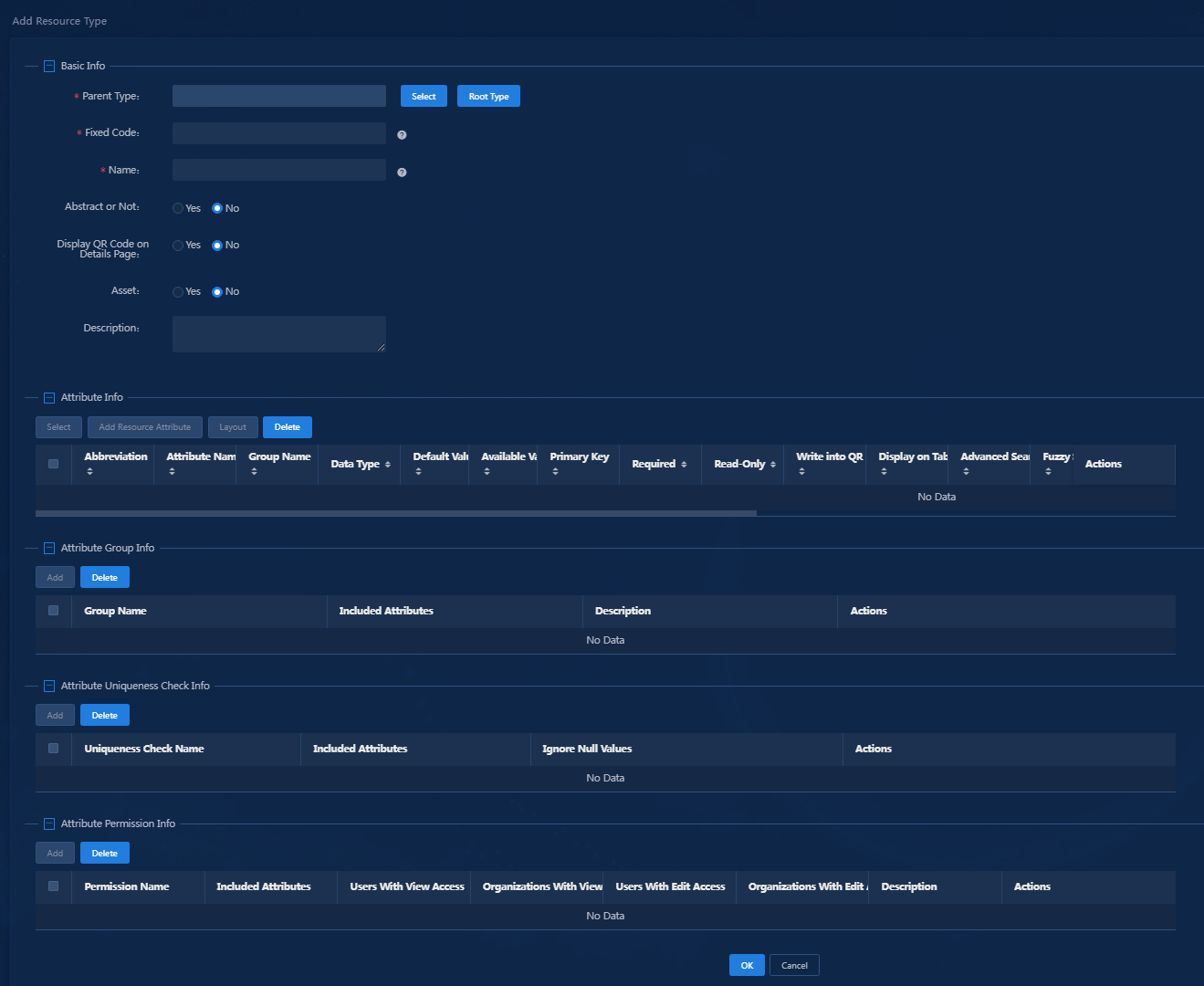
3. Click Add. The Add Resource Type page appears, as shown in Figure 2.
Figure 2 Creating a resource type
|
|
NOTE: Different resource types have different parameters. This example uses the UniServer R4900 G3 Server resource type to illustrate the configuration. |
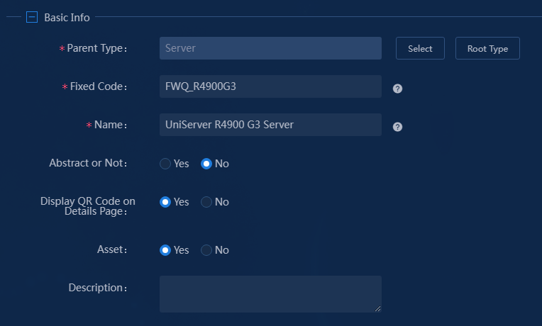
4. Configure the basic information.
Figure 3 Configuring basic information
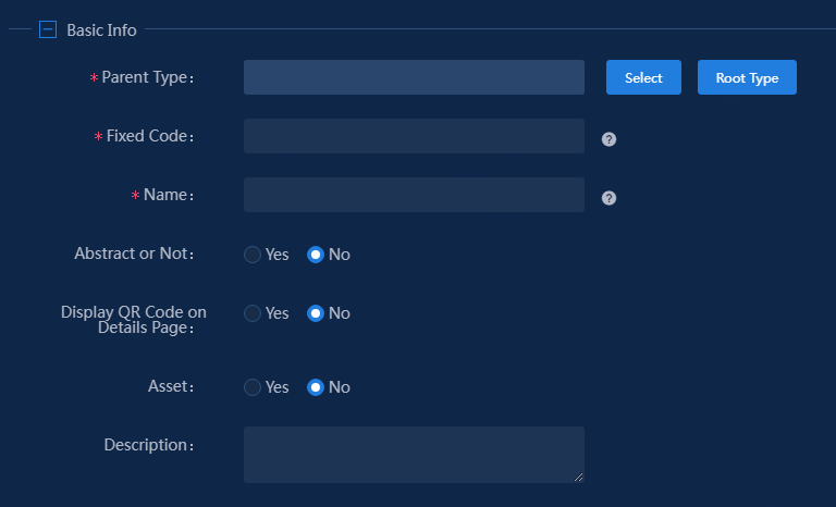
The parameters in the basic information area are as follows:
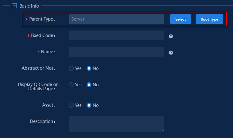
¡ Parent Type: Add a specific instance type based on an existing resource type (parent type), or add a resource type from scratch. The former can inherit a resource attribute set of a certain resource type, while the latter inherits all public attributes. This example selects a parent type.
|
|
NOTE: Resource attributes can be divided into common attributes and custom attributes. CMDB supports adding common and custom attributes, as well as upgrading custom attributes to common attributes. |
a. Click Select. The Select Resource Type window opens, as shown in Figure 4.
Figure 4 Selecting a resource type
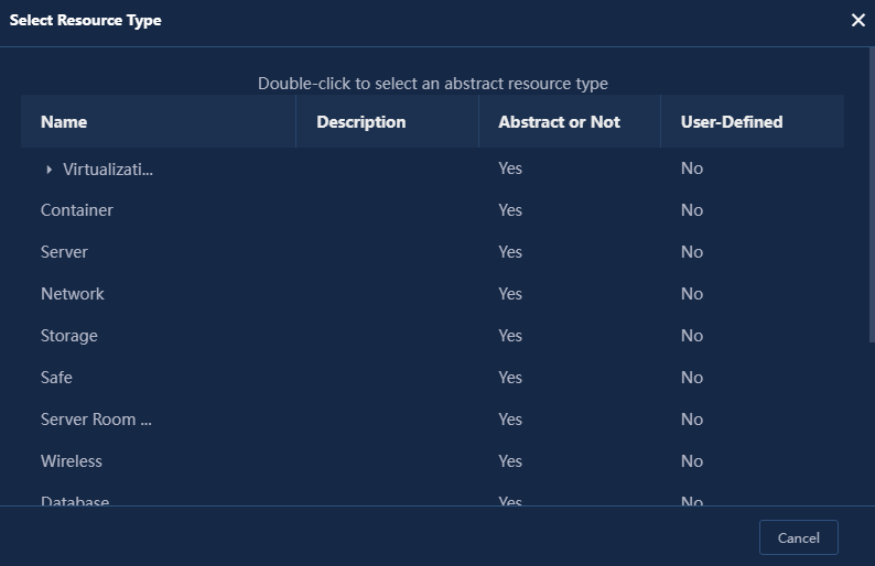
b. Double-click Server in this example
Figure 5 Parent type
¡ Fixed Code: Enter a unique identifier for the resource type. Enter FWQ_R4900G3 in this example.
¡ Name: Enter a name for the resource type. Enter UniServer R4900 G3 Server in this example.
¡ Abstract or Not: Select whether the resource type is an abstract type or a non-abstract type. Only abstract types can be inherited. Select No in this example.
- Yes: An abstract resource type serves as a basic template for other specific resource types and can be inherited and extended as a parent type. It describes the common attributes and characteristics of a resource type.
- No: A non-abstract resource type cannot be used as a parent type for inheritance and extension. It is a concrete resource type that represents actual instances.
¡ Display QR Code on Details Page: Configure whether to display the QR code on the details page. Selects Yes in this example.
¡ Asset: Select whether the resource type is considered as an asset. If yes, the attributes in the asset group will be added to this resource type. Selects Yes in this example.
¡ Description: Enter a description about this asset type. This example does not require this parameter.
Figure 6 shows the configuration in this example.
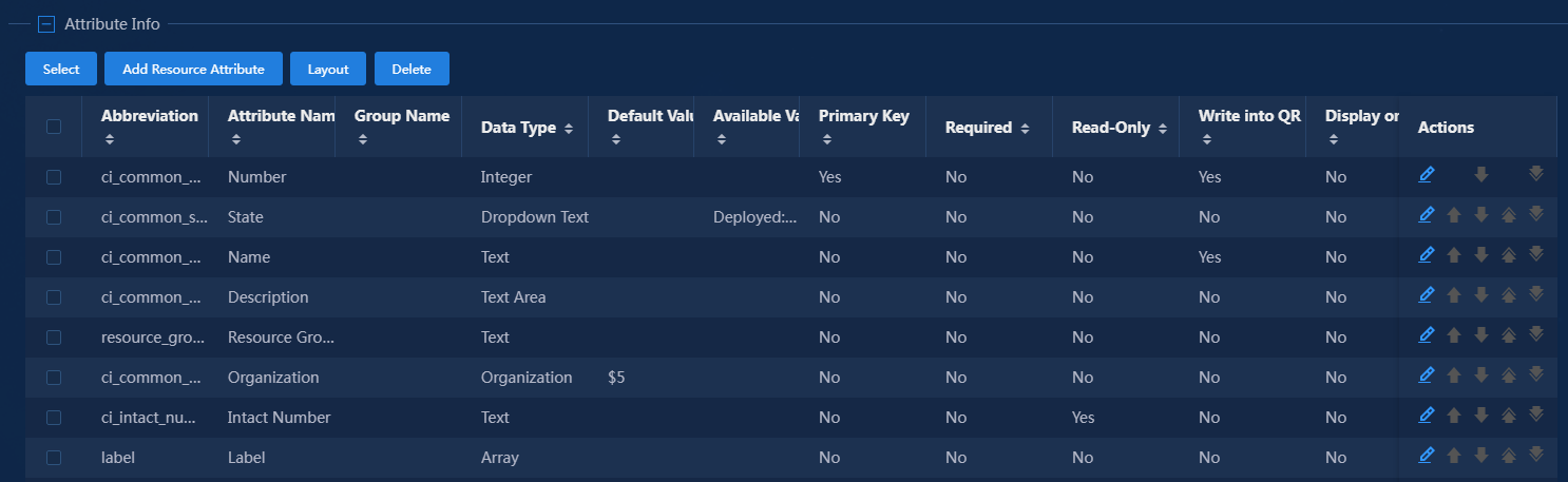
5. Configure attributes.
In this area, you can manage resource attributes. After the basic information configuration, all resource attributes containing the parent type server and all resource attributes in the asset group are included in the current attributes. On this basis, you can add, modify, and delete resource attributes. This example uses the default attributes, some of which are shown in Figure 7.
|
|
NOTE: · Common attributes and parent type attributes vary by environment. The attributes are only for demonstration. · For explanations of the parameters for each attribute, see the online help. |
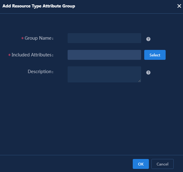
6. Configure an attribute group.
In the Attribute Group Info area, you can group the resource attributes of the current resource type (the attributes in the Attribute Info area) for easier management of the resource type attributes. By default, the attributes are not grouped. Use the default setting in this example.
Figure 8 Attribute group
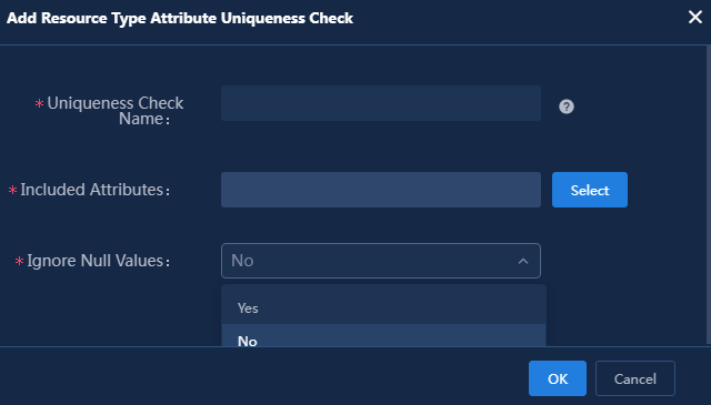
7. Configure attribute uniqueness check.
Configure uniqueness check information for the resource attributes, including single attribute uniqueness, multi-attribute uniqueness, and whether to ignore null values. By default, uniqueness check is not configured. Use the default setting in this example.
Figure 9 Attribute uniqueness check
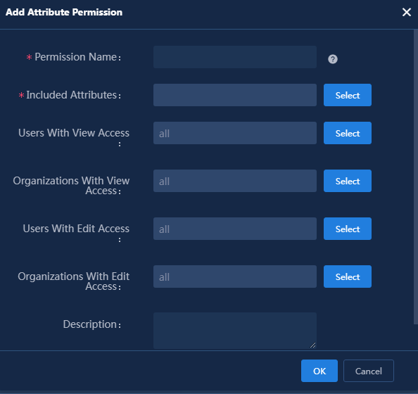
8. Configure attribute permission.
By controlling the permissions of various resource attributes in the resource type, you can manage permissions of the resource type. You can limit the users and organizations that can be viewed and modified. Use the default setting in this example.
Figure 10 Attribute permissions
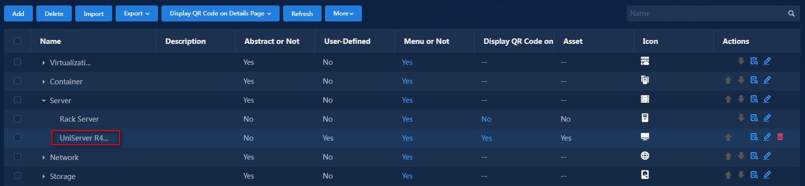
9. Click OK to complete the addition of the resource type. The newly added resource type is displayed in the resource type list, as shown in Figure 11.
Figure 11 UniServer R4900 G3 Server resource type
Incorporating resource instances
CMDB supports manual and automatic incorporation of instance resources.
Manually incorporating resource instances into CMDB
1. Log in to U-Center.
2. On the top navigation bar, click the Resource tab. From the left navigation tree, select Maintain Resources.
3. On the resource maintenance page, select the UniServer R4900 G3 Server resource type from the resource tree on the left.
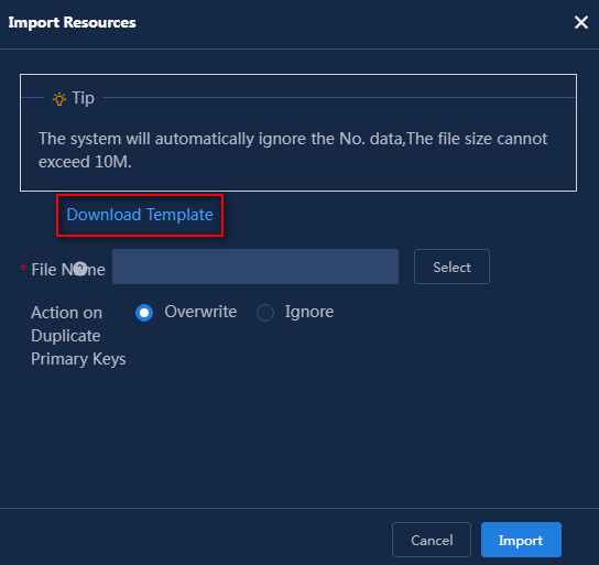
4. Hover over Import, and select Import Resources from the list.
5. In the dialog box that opens, click Download Template to download the template for the current resource type and import resources according to the template. (Details not shown.)
Automatically incorporating resource instances into CMDB
The following methods are available for automatically incorporating resource instances into CMDB for management:
· By configuring an automatic discovery task.
· By enabling configuration polling when adding a monitor (Add as Config Poll Object).
This example describes the first method: configuring a resource discovery task. For more information about enabling the configuration polling feature, see H3C U-Center 2.0 Configuration Examples.
|
|
TIP: To automatically incorporate resource instances into CMDB, first configure a resource synchronization policy for the resource type. Otherwise, discovered resource instances may not be automatically added to the resource type. For information about how to configure a resource synchronization policy, see “Configuring a resource synchronization policy." |
To automatically incorporate resource instances into CMDB:
1. Log in to U-Center.
2. On the top navigation bar, click the Resource tab. From the left navigation pane, select Resource Discovery > Discovery Tasks.
3. Click Add. On the page that opens, add a new discovery task.
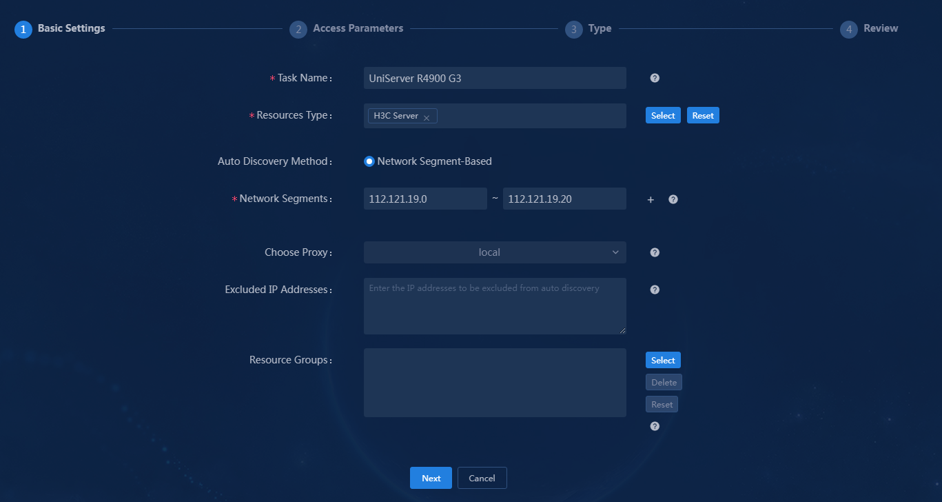
4. Configure basic settings. Fields marked with a red asterisk (*) are required parameters. This example configures only the required parameters. You can configure optional parameters as needed.
Figure 13 Discovery task - Basic Settings
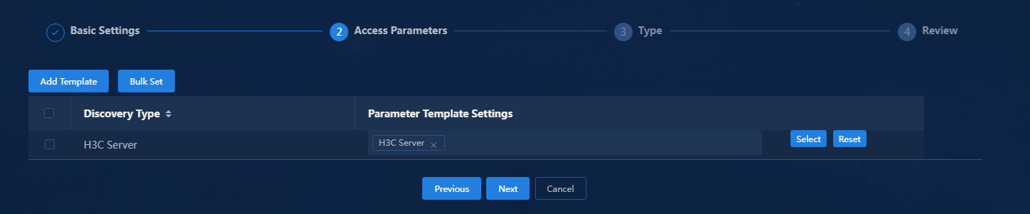
5. Click Next to configure access parameters. Click Select to select a parameter template or create a custom one. This example uses the H3C Server template.
Figure 14 Discovery task - Access Parameters
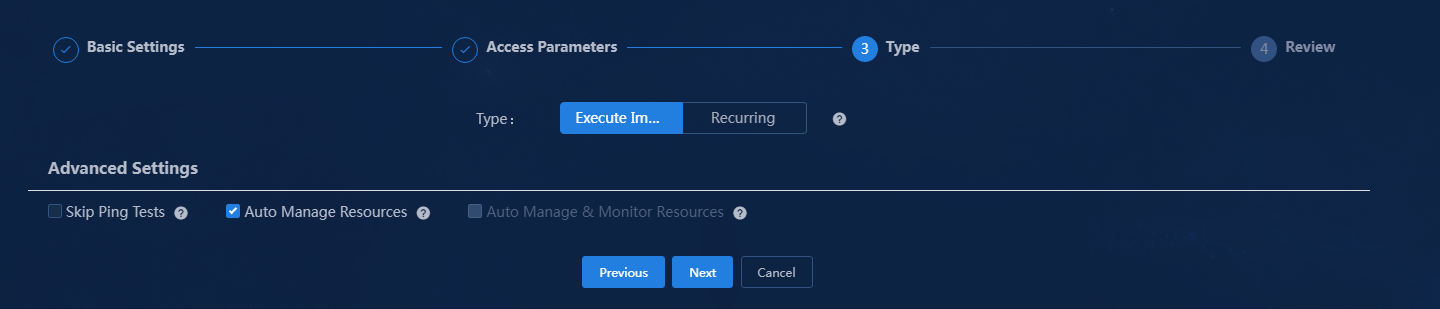
6. Click Next to select the task execution type and advanced settings. This example selects the Execute Immediately type and the Auto Manage Resources option.
¡ Skip Ping Tests: The discovery task will not perform a preliminary ping test. This option is only for specific environments where ping is blocked but protocol ports are accessible. Selecting this option might significantly increase the execution time of the task.
¡ Auto Manage Resources: After the task is executed, the system automatically incorporates the discovered resources without monitoring them.
¡ Auto Manage and Monitor Resources: After the task is executed, the system automatically incorporates and monitors and discovered resources.
Figure 15 Discovery task - Access Parameters
7. Click Next to review task information.
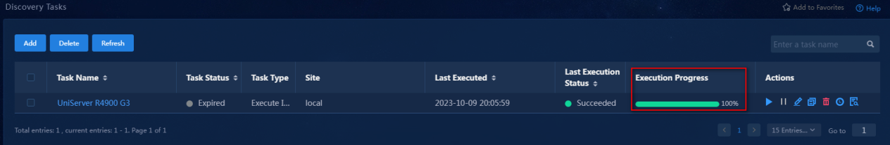
8. Verify that the task configuration is correct and then click OK button to deploy the task. You can view the progress of task execution on the Discovery Tasks page.
Figure 16 Viewing the progress of the task (execution complete)
9. After waiting for a while, click Maintain Resources in the left navigation pane.
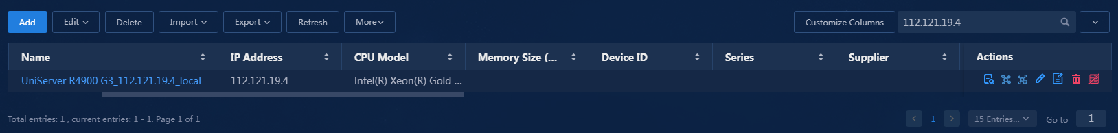
10. Select Servers > UniServer R4900 G3 Server in the resource tree on the resource maintenance page to view the incorporated resource instances. The resource instance has now been successfully incorporated under the UniServer R4900 G3 Server resource type.
Figure 17 Viewing resource instances
Configuring a resource synchronization policy
After creating a data resource type, you can manually import resource instances to this type or configure CMDB to automatically add resource instances of this type. For CMDB to automatically add resource instances of a resource type, you must configure a resource synchronization policy for the resource type.
To configure a resource synchronization policy:
1. Log in to U-Center.
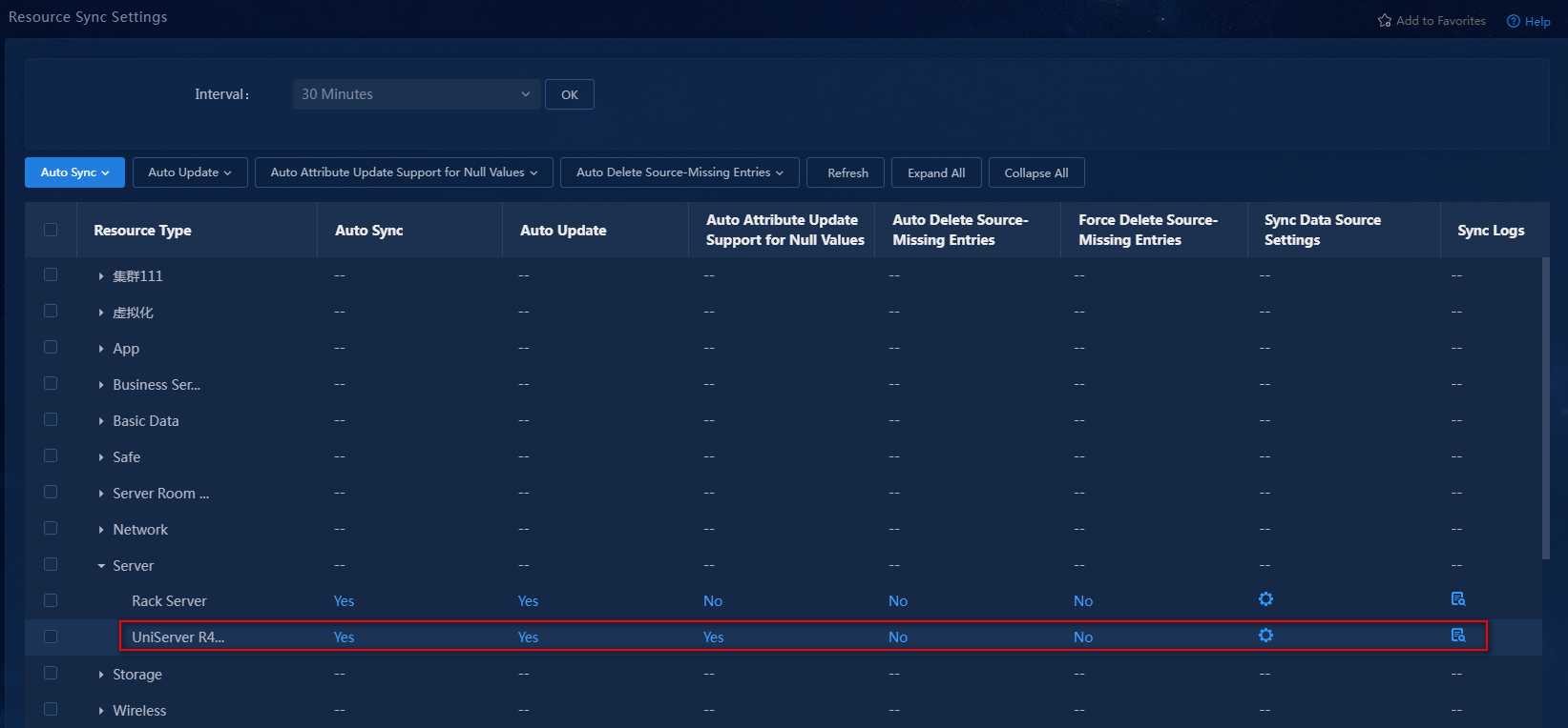
2. On the top navigation bar, click the Resource tab. From the left navigation pane, select Resource Types > Resource Sync Settings.
Figure 18 Resource sync settings
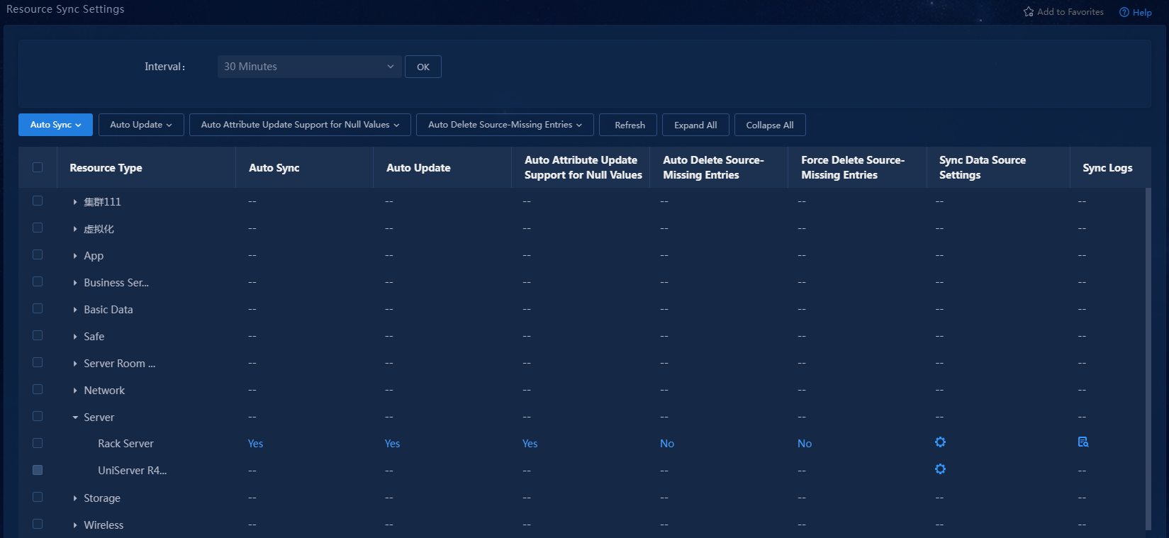
3. Expand the Server resource type and
locate the newly created UniServer R4900 G3 Server.
Click the ![]() icon in the Sync Data Source Settings
column for the server. The Sync Data Source Settings
page opens.
icon in the Sync Data Source Settings
column for the server. The Sync Data Source Settings
page opens.
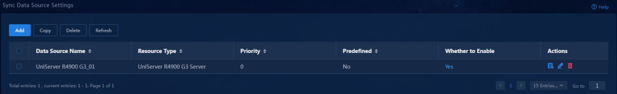
4. Click Add. The Add Data Sync Source page opens.
Figure 19 Adding a sync data source
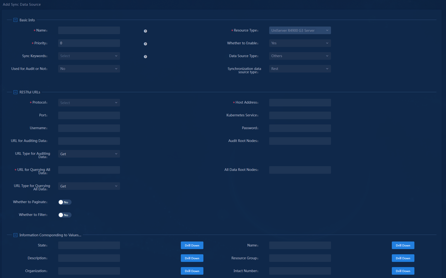
¡ Select a data source type. Options include IOM, Config Polling, Config Polling Index, and Others. This example selects Config Polling.
- IOM: Only required resource attributes in the CMDB can be synchronized from IOM. This is not recommended.
- Config Polling: This allows for visual operation for all resource attributes and collection indexes. You can configure all fields available for data collection via drag and drop, and set a calculation type such as sum, maximum, minimum, total count, and concatenation for the fields. Once you set a calculation type for a resource attribute field, this attribute will display the calculation result directly when you view resource details. This feature requires a CMDB node license.
- Config Polling Index: Model each item of a resource instance as a separate CI for data synchronization.
- Others: Data source synchronization settings can only be configured via code. This type supports REST and Python.
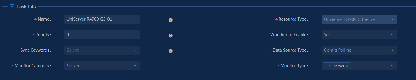
¡ Configure the required parameters, including name, priority (the default is 0), the monitor category, and monitor type. In this example, select Server as the monitor category and H3C Server as the monitor type.
|
|
NOTE: If the monitor type is a predefined type, exclude this monitor type from the predefined resource synchronization configuration. |
¡ Configure basic information.
Figure 20 Adding a sync data source—basic information
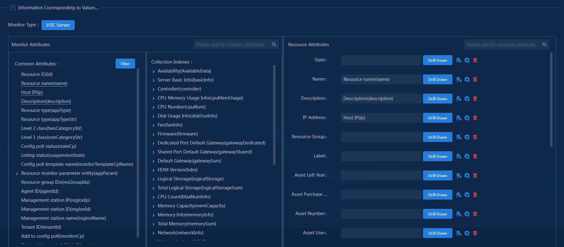
¡ Drag monitor attributes to the resource attribute area as needed.
Figure 21 Adding a sync data source—Information corresponding to values
5. Click OK.
Figure 22 Sync data source added
6. Access the Resource Sync Settings page and set up the resource synchronization policy.
Figure 23 Resource sync settings
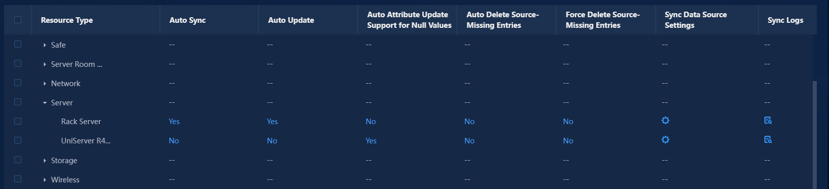
Key parameters in the list:
¡ Auto Sync: Indicates whether to automatically sync resource data from the corresponding data source to CMDB. In this example, the setting for this parameter is Yes.
¡ Auto Update: Indicates whether to replace the current data with the new data read automatically. In this example, the setting for this parameter is Yes.
¡ Auto Attribute Update Support for Null Values: Indicates whether to replace current data with a null value when the data source returns a null value. In this example, the setting for this parameter is No.
¡ Auto Delete Source-Missing Entries: When a read operation detects a resource entry whose data source no longer exists and the resource entry is not used in any topology or maintained manually, the system will automatically delete that resource entry. In this example, the setting for this parameter is No.
¡ Force Delete Source-Missing Entries: When a read operation detects a resource entry whose data source no longer exists, the system will automatically delete that resource entry. In this example, the setting for this parameter is No.
¡ Sync Data Source Settings: Click the ![]() icon
to access the sync data source configuration page. For specific operations, see
step 3 through
step 4 in this
section.
icon
to access the sync data source configuration page. For specific operations, see
step 3 through
step 4 in this
section.
¡ Sync Logs: Click the ![]() icon
view the resource synchronization log for this type of resource.
icon
view the resource synchronization log for this type of resource.
Figure 24 Resource sync policy configured
Creating resource relationships
CMDB provides rich pre-defined resource relationships and also supports flexible custom resource relationships. CMDB establishes relationships between resources based on data match rules, and the relationships between resource instances can be automatically generated according to relationship rules.
The following are the steps for creating associations between resource instances.
Adding resource relationship establishment rules
1. Log in to U-Center.
2. On the top navigation bar, select the Resource tab. From the left navigation tree, select Resource Relationships > Resource Relationship Management.
3. Click Add to configure resource relationships.
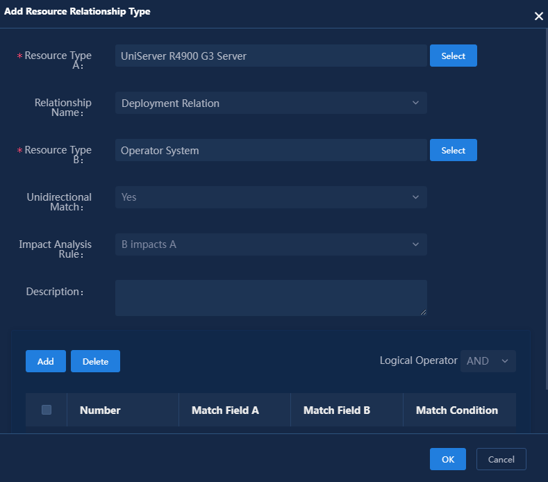
4. Click Select and select resource type A, resource type B, and relationship names. This document uses the deployment relationship between the configuration server and the operating system as an example. Figure 25 shows the configuration in this example.
¡ Unidirectional Match: Select whether the relationship between the resource types is unidirectional. For example, resource type A and resource type B establish a containment relationship. If it is a unidirectional match, resource type A can contain resource type B, but resource type B cannot contain resource type A.
¡ Impact Analysis Rule: Select an option from no impact, A impacts B, B impacts A, and mutual impact. The impact on surrounding nodes and connections after the interruption of the current device can be simulated in the resource topology.
Figure 25 Adding a resource relationship type
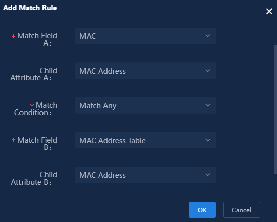
5. Click Add to configure relationship match rules. If the MAC address in the MAC table of the UniServer R4900 G3 Server matches any MAC address in the MAC address table of the operating system, the operating system is deployed on that server. The relationship match rule configuration is shown in Figure 26.
Figure 26 Relationship match rule
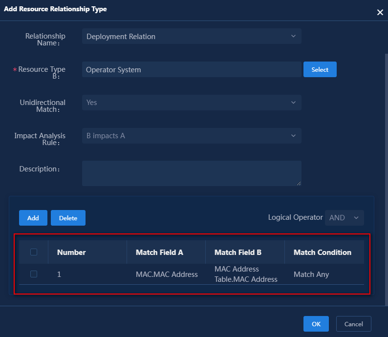
6. Click OK. Figure 27 shows the match rule.
Figure 27 Added relationship match rule
7. Click OK. Figure 28 shows the resource relationship.
Figure 28 Added resource relationships
![]()
Generating a resource instance relationship
1. After addition of the resource relationship, select the resource relationship on the resource relationship management page, and click Generate Resource Relationship.
2. Click OK to start generating a resource relationship.
3. After several minutes, click the ![]() icon
for the resource relationship on the resource relationship management page to
view its information.
icon
for the resource relationship on the resource relationship management page to
view its information.
Configuring resource attribute associations
The attribute association facilitates users to view important attribute information of a resource type and the associated resource types. For example, the Asset Admin attribute value of the Server resource type corresponds to the Nam" of the Service Provider. Users can associate the two by configuring the attributes. When users view the information of the Server resource, they can see the service provider's name and contact information.
1. Log in to U-Center 2.0.
2. On the top navigation bar, select the Resource tab. From the left navigation tree, select Resource Types > Resource Relationship Settings.
3. Click Add to open the attribute association configuration page.
4. Configure a relationship type as shown in Figure 29.
Figure 29 Attribute association configuration
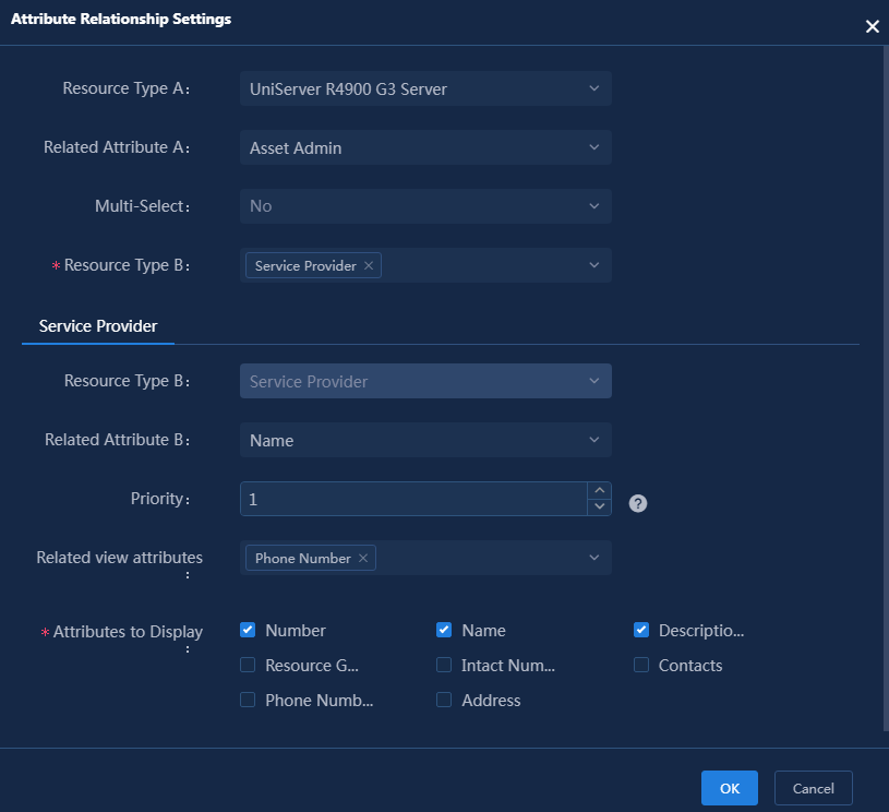
¡ Resource Type A: Select the name of resource type A configured in the attribute association. Select UniServer R4900 G3 Server in this example.
¡ Related Attribute A: Select the name of the associated attribute A in the attribute association. Select Asset Admin in this example.
¡ Multi-Select: Select Yes if multiple attribute values need to be associated with related attribute B. The default setting is No. Use the default setting in this example.
¡ Resource Type B: Select the name of resource type B configured in the attribute association. Select Service Provider in this example.
¡ Related Attribute B: Select the name of the associated attribute B in the attribute association. Select Name in this example.
¡ Priority: Set the priority of the attribute association to an integer in the range of 1 to 20. The smaller the number, the higher the priority. Set the priority to 1 in this example.
¡ Associated View Attributes: Select associated view attributes of the attribute association. Select Phone Number in this example. See Figure 47 in "Viewing attribute associations" for the displayed attributes.
¡ Attributes to Display: Select the attributes to be displayed in the attribute association list. In this example, select Number, Name, and Description. See Figure 48 in "Viewing attribute associations" for the displayed attributes.
5. Click OK to complete the addition. The attribute association will be displayed in the attribute association list on the attribute association configuration page, as shown in Figure 30.
Figure 30 Added attribute association

Configuring topologies for resource data display
CMDB supports presenting resource data in the form of topology diagrams (service topology and resource topology), creating a comprehensive resource map. You can conveniently view and edit all information related to configuration items at the top of the page, including configuration item data and alarm data.
· Service Topology: Displays resource relationships based on CMDB resource information, using a layered structure. To use the service topology feature, purchase the relevant BSM product licenses for the quantity and feature.
· Resource Topology: Displays the relationships between resources using CMDB resource information as the base data and CMDB resource relationships as the data source, and supports the creation of cloud diagrams.
Synchronizing resource types to the topology
The topology already has information for the system predefined resource types. You do not need to synchronize these resource types into the topology. For new resource types, you must sync the information of the resource types to the topology. To synchronize a resource type to the topology:
1. Log in to U-Center.
2. On the top navigation bar, click the Resource tab. From the left navigation pane, select Topology Settings > Resource Mappings.
3. Click Add. In the window that opens, configure the parameters as needed. The name and resource type are required. Enter the name and select the newly added resource type. For descriptions of other parameters, see the online help for the page.
Figure 31 Adding a resource mapping
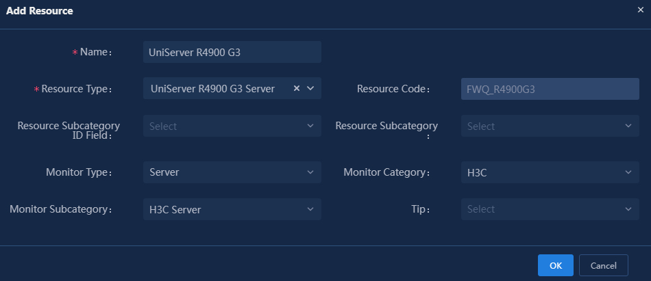
4. Click OK.
5. From the left navigation pane, select Topology Settings > Topology Resource Groups.
6. Select Service/Service Relationship Topology or Topology to access the corresponding page. The operations on both pages are identical. This example uses the Topology page to illustrate the configuration.
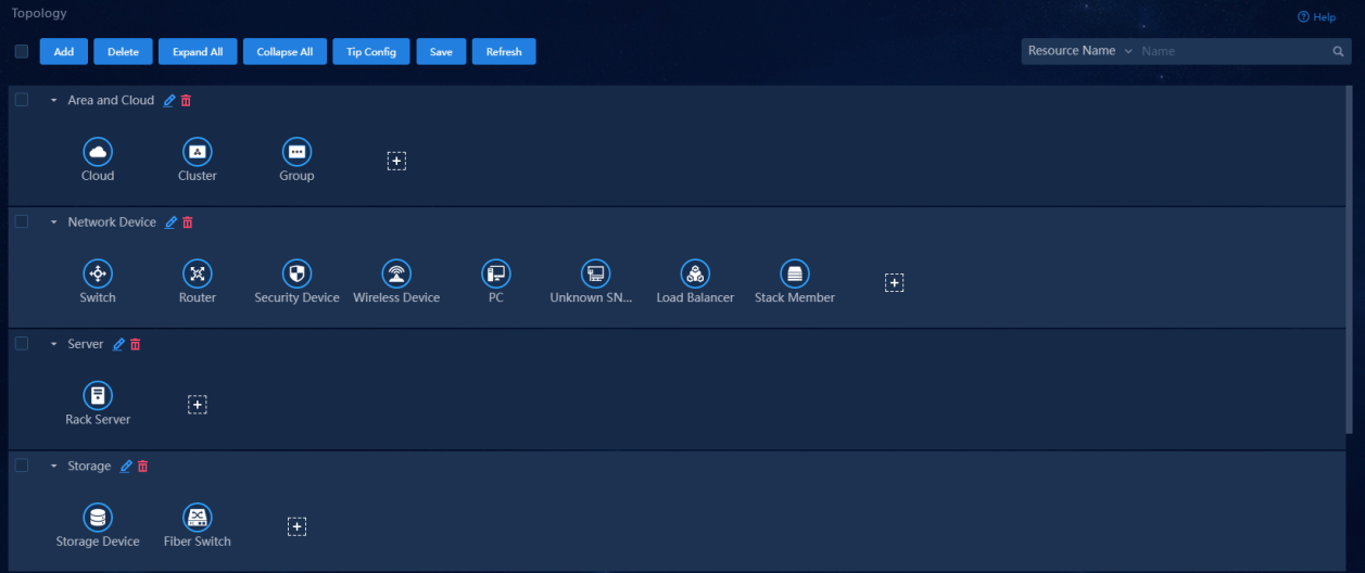
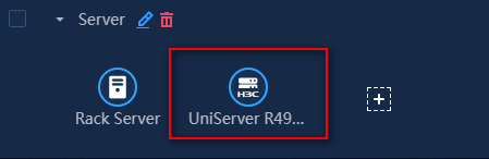
7. Click the ![]() icon to open the Add Resource window.
icon to open the Add Resource window.
8. In the window, select the resource type you want to synchronize to the topology. In this example, select UniServer R4900 G3.
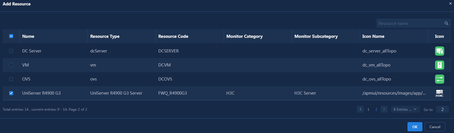
9. Click OK to synchronize the current resource type to the topology.
Figure 34 Synchronizing resource types to the topology
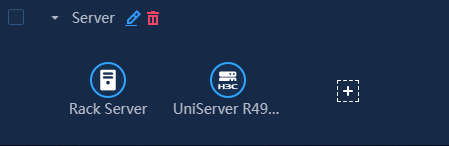
10. Click Save.
11. You can synchronize the resource type to the Service/Service Relationship Topology in the same way.
Creating a topology
1. Log in to U-Center.
2. On the top navigation bar, click the Resource tab. From the navigation pane, select Resource Topology.
3. Hover over the Resource
Topology directory on the left, and the ![]() button will
appear on the right.
button will
appear on the right.
|
|
NOTE: The steps to create a resource topology and a service topology are the same. This example describes how to create a resource topology. |
4. Hover over the ![]() button
and select Add View from the displayed menu.
button
and select Add View from the displayed menu.
5. Configure the resource topology as needed.
Figure 35 Add Resource Topology
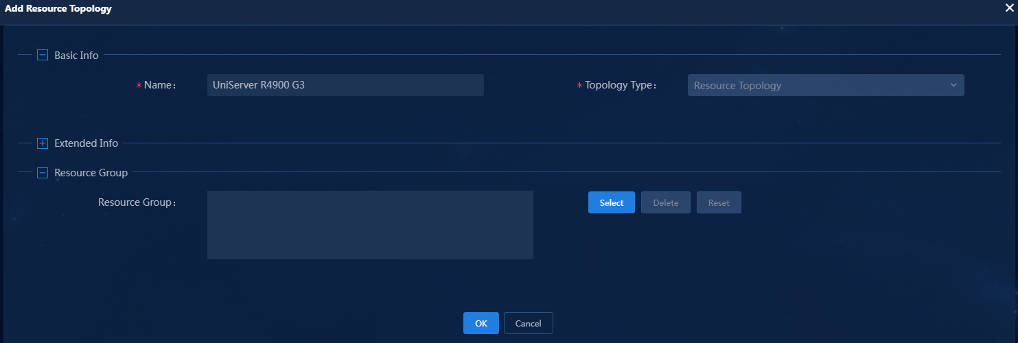
6. Click OK.
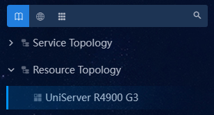
Figure 36 Adding H3C UniServer R4900 G3 server topology
Drawing a resource topology
1. Log in to U-Center.
2. On the top navigation bar, click the Resource tab. From the navigation pane, select Resource Topology.
3. In the directory on the left, expand Resource Topology, and then click the topology you wish to draw. The preview pane on the right will display this topology diagram.
4. Click the ![]() icon in the upper
right corner to enter edit mode for the view.
icon in the upper
right corner to enter edit mode for the view.
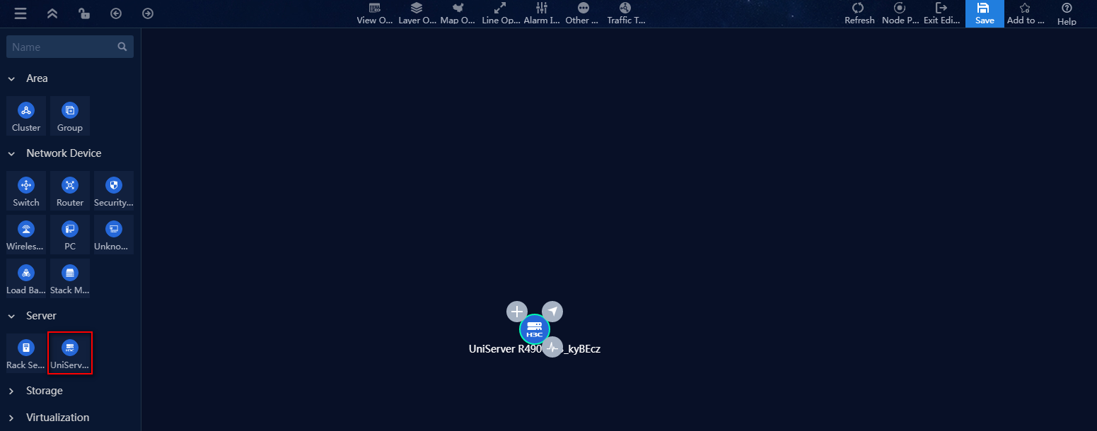
5. Drag the UniServer R4900 G3 server topology onto the canvas.
Figure 37 Drawing a resource topology
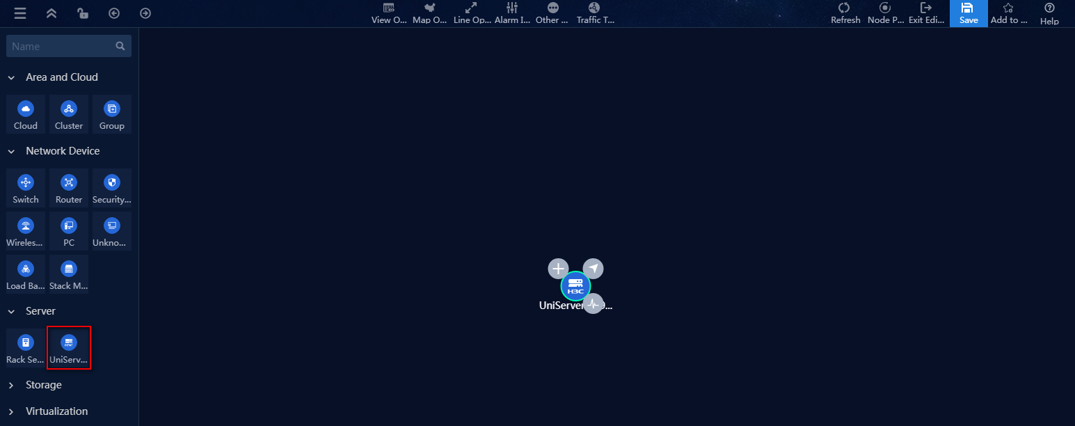
6. Click the ![]() icon on the node
to select a resource instance for this topology node in the pop-up window. Or,
click the
icon on the node
to select a resource instance for this topology node in the pop-up window. Or,
click the ![]() icon to add new a resource instance on the topology diagram.
icon to add new a resource instance on the topology diagram.
|
|
NOTE: · The resource topology supports the cloud diagram feature. To create a cloud diagram view, select Cloud in the Area and Cloud area and drag it onto the canvas. You can then draw sub-topology diagrams within the cloud diagram view. · The topology page offers a rich and flexible drawing experience, including setting backgrounds, displaying grids, and connecting lines. For drawing methods, see the page help or the H3C U-Center CMDB 2.0 User Guide. This example does not provide a detailed introduction. |
7. After completing the drawing, click the ![]() icon
to save the topology view.
icon
to save the topology view.
Drawing a service topology
1. Log in to U-Center.
2. On the top navigation bar, click the Resource tab. From the navigation pane, select Resource Topology.
3. In the directory on the left, expand Service Topology and then click the topology you wish to draw. The preview pane on the right will display the selected topology.
4. Click the ![]() icon in the upper
right corner to enter edit mode for the view.
icon in the upper
right corner to enter edit mode for the view.
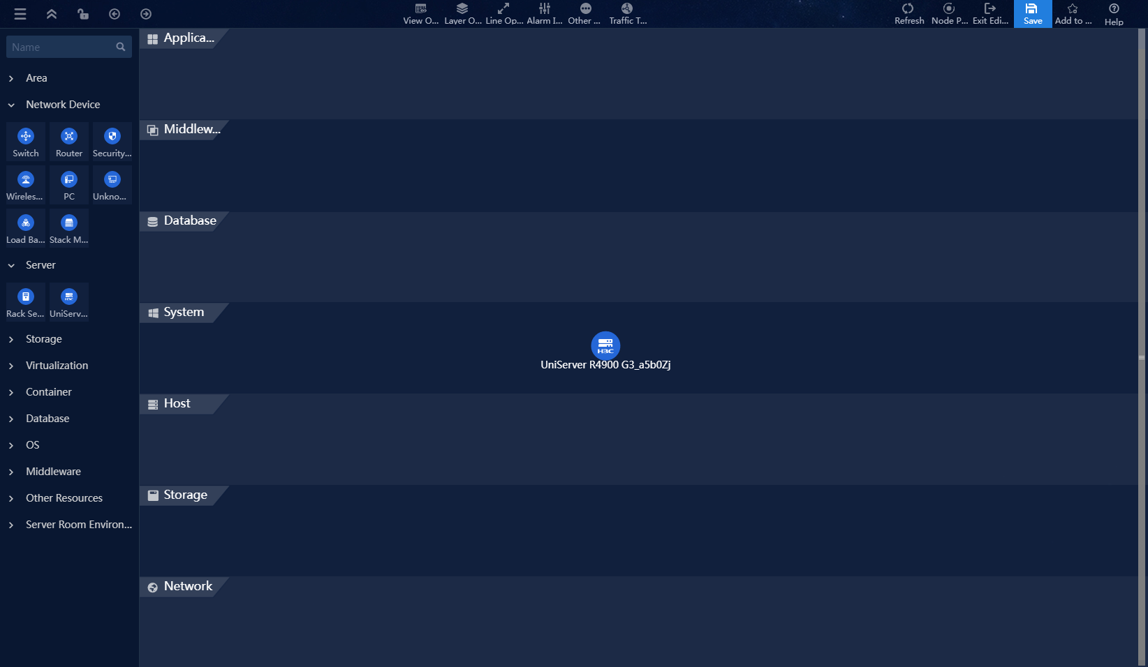
5. Drag the UniServer R4900 G3 server topology into the right pane.
Figure 38 Drawing a service topology
6. The service topology supports layered operations. Select the Layer Operations > Show Layers menu item in the top toolbar to display the current topology's layers.
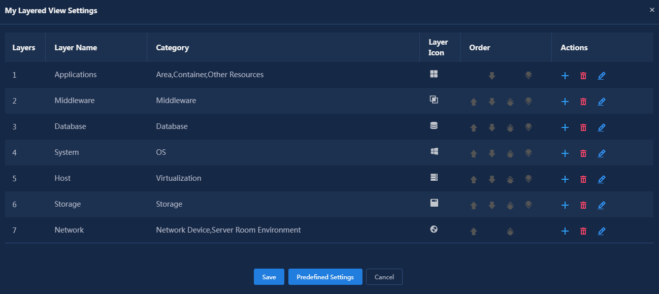
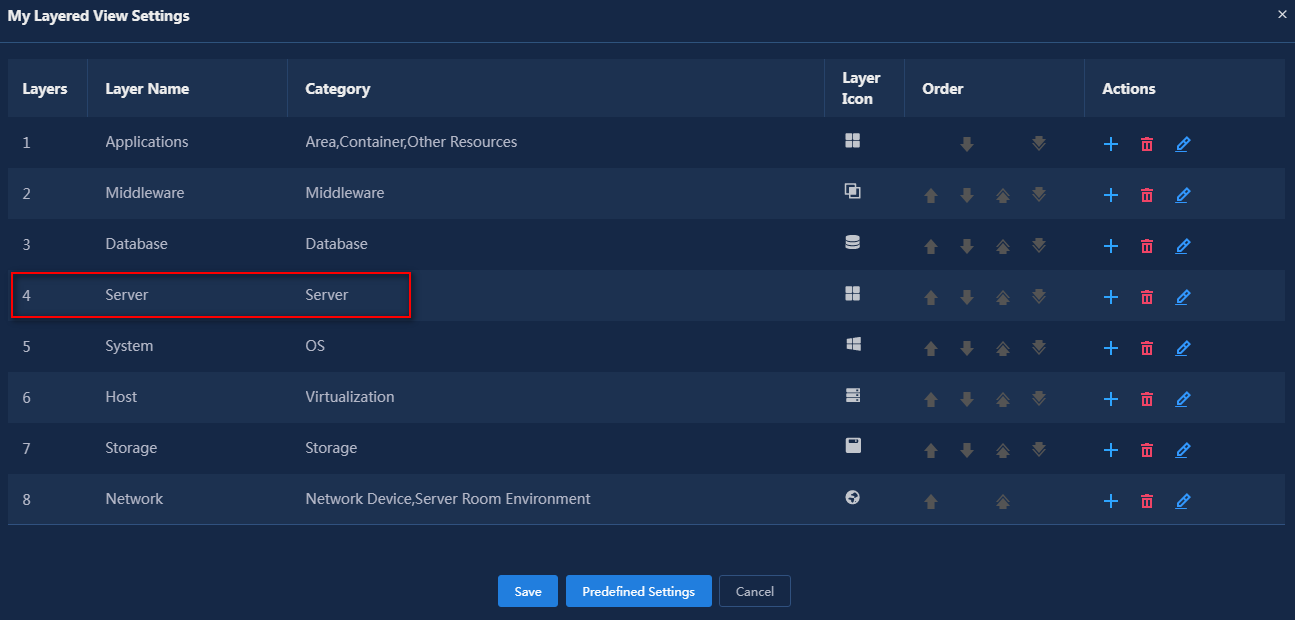
7. Select the Layer Operations > Layer Settings menu item from the top toolbar to customize layer information.
Figure 40 Layer settings 1
8. To insert a Server
layer between Database and System,
click the ![]() icon in the Actions column for Database.
icon in the Actions column for Database.
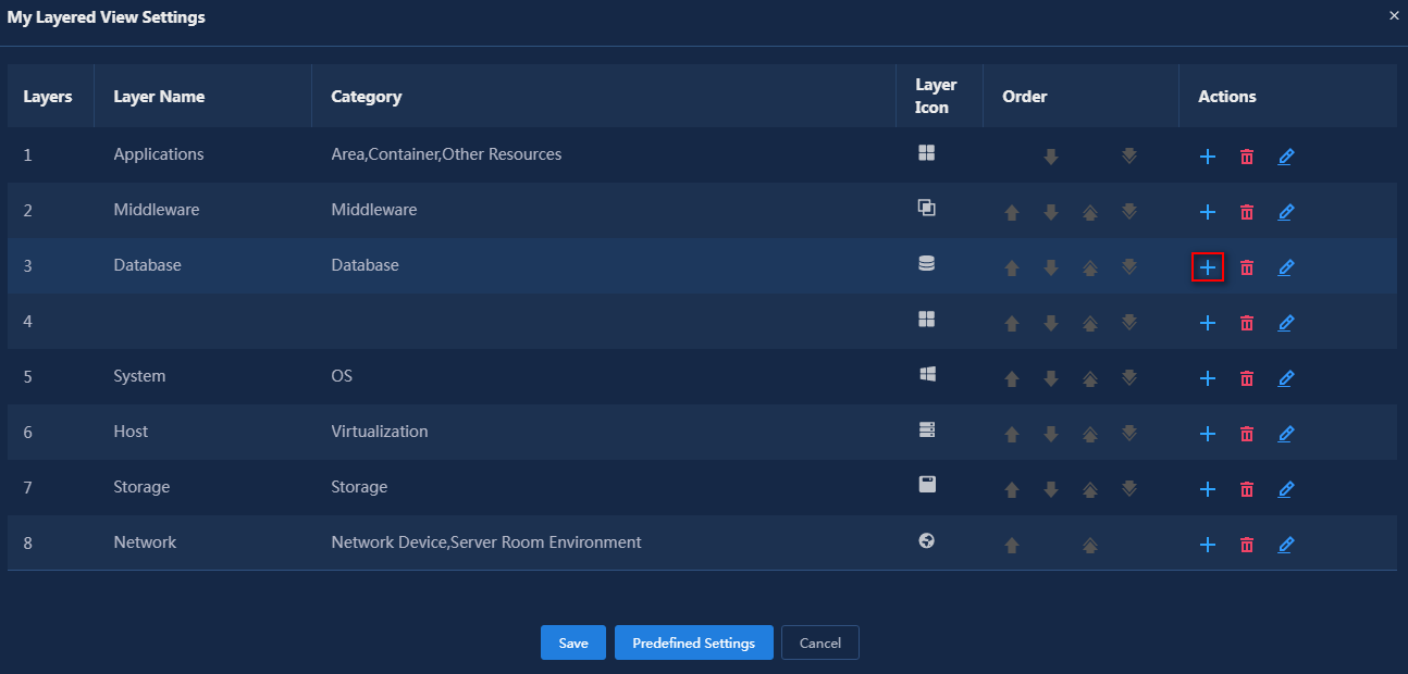
9. Click the ![]() icon in the blank
line to edit it.
icon in the blank
line to edit it.
10. After editing, click the ![]() icon
to save the editing.
icon
to save the editing.
11. Click Save.
12. Select Layer Operations > Layered Layout from the top toolbar to display the current topology in a layered view.
Figure 43 Layered Layout
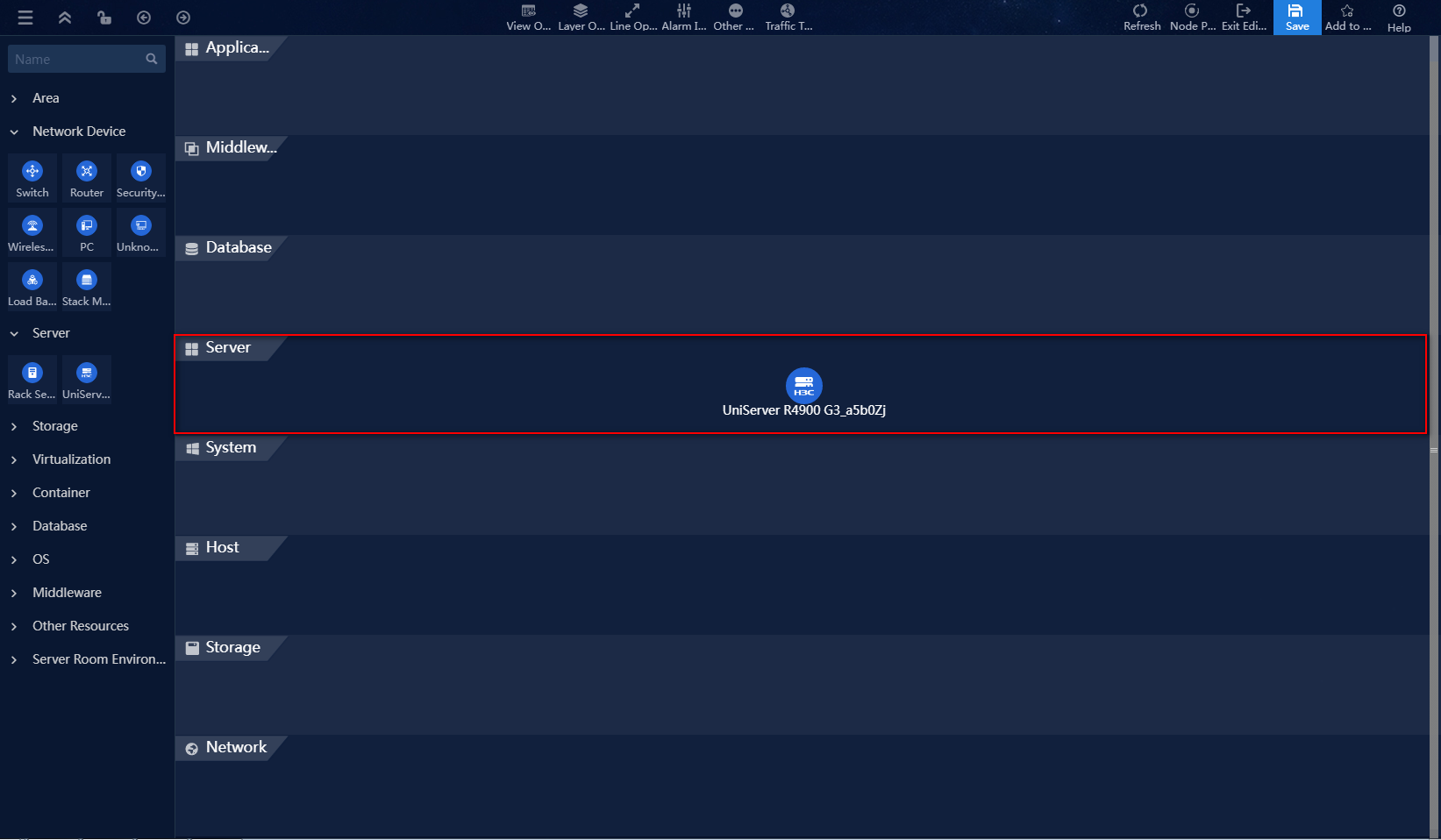
13. Click the ![]() icon on the node
to select a resource instance for this topology node in the pop-up window. Or,
click the
icon on the node
to select a resource instance for this topology node in the pop-up window. Or,
click the ![]() icon to add new a resource instance on the topology diagram.
icon to add new a resource instance on the topology diagram.
|
|
NOTE: The topology page offers a rich and flexible drawing experience, including setting backgrounds, displaying grids, and connecting lines. For drawing methods, see the page help or the H3C U-Center CMDB 2.0 User Guide. This example does not provide a detailed introduction. |
14. After completing the drawing, click the ![]() icon
to save the topology view.
icon
to save the topology view.
Verifying the configuration
Viewing resource relationships
1. Log in to U-Center.
2. On the top navigation bar, select the Resource tab. From the left navigation tree, select Resource Relationships > Resource Relationship Management.
3. On the resource relationship management
page, click the ![]() icon for resource relationship, as shown in Figure 44.
icon for resource relationship, as shown in Figure 44.
Figure 44 Viewing resource relationships

4. CMDB supports presenting the relationships between resources in a graphical topology.
a. Select Maintain Resources from the left navigation tree.
b. Select Server > UniServer R4900 G3 Server from the left resource tree.
c. Click ![]() button to view
the topology, as shown in Figure 45.
button to view
the topology, as shown in Figure 45.
Figure 45 Resource mapping topology

Viewing attribute associations
1. Log in to U-Center.
2. On the top navigation bar, select the Resource tab. From the left navigation tree, select Maintain Resources.
3. Select Server > UniServer R4900 G3 Server from the left resource tree.
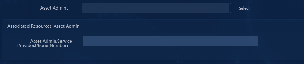
4. Click the ![]() icon. Select Asset Admin and the Name
attribute of service provider, as shown in Figure 46.
icon. Select Asset Admin and the Name
attribute of service provider, as shown in Figure 46.
Figure 46 Viewing attribute associations
5. Click Select and select resources. As shown in Figure 47, the fields displayed in this list are the attributes to display configured in "Configuring resource attribute associations."
Figure 47 Attribute association—selecting resources
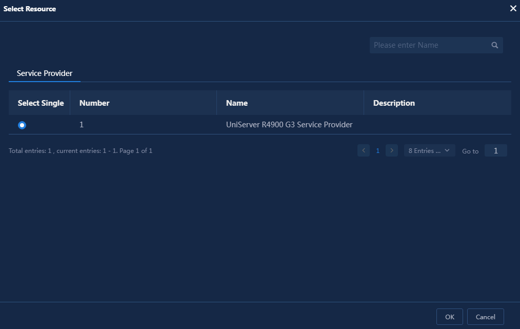
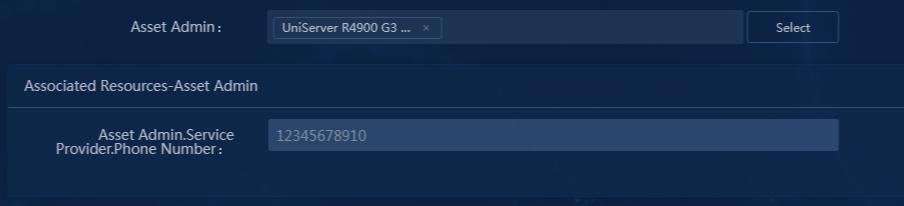
6. Click OK to select Asset Admin for the resource type. As shown in Figure 48, the associated resources area of this attribute displays the related view attributes configured in "Configuring resource attribute associations."
Figure 48 Related view attributes