- Released At: 27-04-2022
- Page Views:
- Downloads:
- Table of Contents
- Related Documents
-
|
|
|
WLAN Radio Load Balancing Technology White Paper |
|
|
|
|
Copyright © 2022 New H3C Technologies Co., Ltd. All rights reserved.
No part of this manual may be reproduced or transmitted in any form or by any means without prior written consent of New H3C Technologies Co., Ltd.
Except for the trademarks of New H3C Technologies Co., Ltd., any trademarks that may be mentioned in this document are the property of their respective owners.
The information in this document is subject to change without notice.
Contents
Session gap threshold-based radio load balancing (on ACs)
Session gap threshold-based radio load balancing (on fat APs)
Band ratio-based radio load balancing (on ACs)
Band ratio-based radio load balancing (on fat APs)
Overview
WLAN radio load balancing dynamically balances clients across radios to ensure wireless service quality and adequate bandwidth for each client.
Technical background
A wireless client scans the working channels periodically even if it has associated with a radio. If the client detects a radio with a higher RSSI, the client will associate with the new radio. As a result, a large number of clients might associate with the same radio and load imbalance will occur. WLAN radio load balancing is developed to resolve this issue.
Benefits
WLAN radio load balancing provides the following benefits:
· Centralized architecture—In an AC+fit AP network, each AP establishes a CAPWAP tunnel to the AC, and the AC performs load balancing across radios of all APs. This enables the AC to monitor the load of each radio and perform radio load balancing in real time.
· Flexible load balancing modes—You can configure radio load balancing on a session gap or band ratio basis.
· Intelligent hiding of an overloaded 5 GHz radio—Enables an overloaded 5 GHz radio to hide its SSID so that new clients will associate with other 5 GHz radios to ensure wireless service quality.
· Hiding SSIDs of overloaded radios—With this feature enabled, a radio hides its SSID when its air interface usage exceeds the specified threshold. Existing clients on the radio will not be affected.
Implementation
Concepts
Session gap threshold based load balancing
Load balancing is performed among radios based on the number of clients associated with each radio.
Band ratio based load balancing
Load balancing is performed among radios based on the ratio between 2.4 GHz clients and 5 GHz clients.
Radio load balancing RSSI threshold
If a radio detects that the RSSI of a client is lower than the specified RSSI threshold, the radio determines that the client is undetectable. The radio participates in load balancing only when the client requests to associate with the radio.
If only an overloaded radio can detect the client, the radio decreases the maximum number of denials to one so that the client has more chances to associate with the radio.
Maximum number of denials for association requests
If the number of times that a radio rejects a client reaches the specified maximum number of denials for association requests, the radio accepts the association request of the client.
Hiding of overloaded 5 GHz radios
With this feature enabled for an AP that has multiple 5 GHz radios, a 5 GHz radio hides its SSID in beacon frames when the following conditions are met:
· The number of clients associated with the 5 GHz radio reaches the session threshold.
· The session gap between the 5 GHz radio and another 5 GHz radio on the same AP reaches the session gap threshold.
When the number of clients associated with the 5 GHz radio falls below the session threshold, the 5 GHz radio stops hiding its SSID in beacon frames.
Hiding SSIDs of overloaded radios
With this feature enabled, a radio hides its SSID when its air interface usage exceeds the specified threshold. When the air interface usage of the radio falls below the threshold, the radio stops hiding its SSID.
Neighbor report
The neighbor report of a client records all radios that detect the client and the RSSI value of the client detected by each radio.
Mechanism
CAPWAP tunnel establishment (on ACs)
In an AC+fit AP network, each AP must establish a control tunnel and a data tunnel to the AC before it provides wireless services. The control tunnel is used for management and monitoring and the data tunnel is used for packet forwarding.
Wireless client tracking
When a radio detects a client, it reports the client information to the AC or fat AP. The AC or fat AP maintains a neighbor report for each client based on the information collected from the radios and ensures the accuracy of the neighbor report through an aging mechanism.
Load balancing decision
Load balancing is performed only among the following radios:
· The radio that a client requests to associate with.
· Radios that detect an RSSI equivalent to or higher than the specified threshold from the client.
When a client requests to associate with a radio, the AC or fat AP identifies whether the load balancing conditions are met. If the load balancing conditions are not met, the radio accepts the association request of the client. If the load balancing conditions are met, the radio rejects the association request of the client, so the client can associate with another radio.
Load balancing conditions are as follows:
|
|
IMPORTANT: The load of a radio is equivalent to the number of clients associated with the radio multiplied by the weight value. The weight values for 2.4 GHz and 5 GHz radios are 2 and 1, respectively. |
· Session gap threshold based—Radio load balancing is performed when the following conditions are met:
¡ The number of clients associated with a radio reaches the session threshold.
¡ The session gap between the radio and the radio that has the fewest clients reaches the session gap threshold.
· Band ratio based—Radio load balancing is performed in the following scenarios:
Scenario 1
¡ A client requests to associate with a 5 GHz radio.
¡ The number of clients associated with the 5 GHz radio reaches the session threshold.
¡ The ratio of clients associated with all 5 GHz neighbor radios to clients associated with all 2.4 GHz neighbor radios of the client is larger than the band ratio.
¡ The load of the radio is higher than the average load of all 5 GHz radios.
Scenario 2
¡ A client requests to associate with a 2.4 GHz radio.
¡ The number of clients associated with the 2.4 GHz radio reaches the session threshold.
¡ The ratio of clients associated with all 5 GHz neighbor radios to clients associated with all 2.4 GHz neighbor radios of the client is smaller than the band ratio.
¡ The load of the radio is higher than the average load of all 2.4 GHz radios.
If the number of times that a radio rejects a client reaches the specified maximum number of denials for association requests, the overloaded radio accepts the association request of the client.
|
|
NOTE: Neighbor radios of a client refer to all radios that receive requests from the client. |
Application scenarios
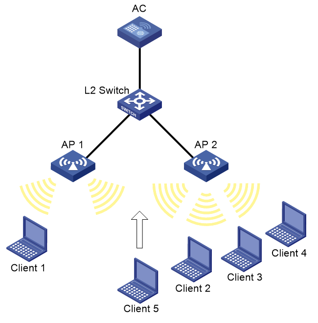
Session gap threshold-based radio load balancing (on ACs)
As shown in Figure 1, AP 1 and AP 2 are managed by the AC and the clients can discover the APs. Client 1 associates with AP 1, and Client 2 through Client 4 associate with AP 2.
Configure the AC to perform radio load balancing on radios of AP 1 and AP 2 when the following conditions are met:
· The number of sessions on a radio of an AP reaches 3.
· The session gap between the radio and the radio that has the fewest sessions reaches 2.
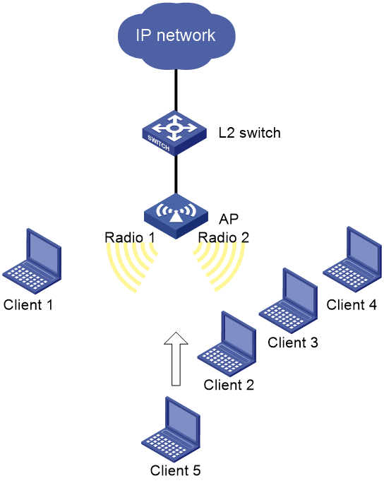
Session gap threshold-based radio load balancing (on fat APs)
As shown in Figure 2, Radio 1 and Radio 2 are enabled on the AP and the clients can discover the radios. Client 1 associates with Radio 1, and Client 2 through Client 4 associate with Radio 2.
Configure the AP to perform radio load balancing on Radio 1 and Radio 2 when the following conditions are met:
· The number of sessions on one radio reaches 3.
· The session gap between the radios reaches 2.
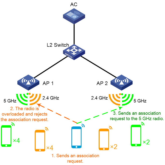
Band ratio-based radio load balancing (on ACs)
As shown in Figure 3, AP 1 and AP 2 are managed by the AC, both 2.4 GHz and 5 GHz radios are enabled on the APs, and the clients can discover the radios. Four clients associate with the 5 GHz radio of AP 1, and four clients associate with the 2.4 GHz radio of AP 1. Two clients associate with the 5 GHz radio of AP 2, and two clients associate with the 2.4 GHz radio of AP 2.
Configure the AC to perform radio load balancing on radios of AP 1 and AP 2 when the following conditions are met:
· A client requests to associate with a 2.4 GHz radio.
· The number of clients associated with the 2.4 GHz radio reaches 4.
· The ratio of clients associated with all 5 GHz neighbor radios to clients associated with all 2.4 GHz neighbor radios of the client is smaller than 2:1.
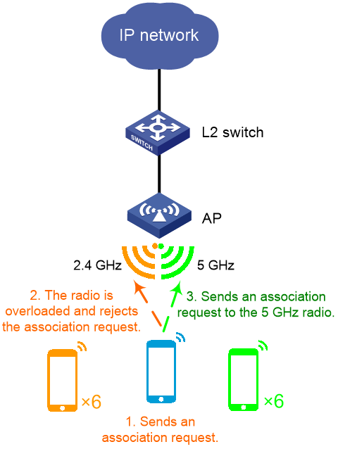
Band ratio-based radio load balancing (on fat APs)
As shown in Figure 4, both 2.4 GHz and 5 GHz radios are enabled on the AP and the clients can discover the radios. Six clients associate with the 5 GHz radio, and six clients associate with the 2.4 GHz radio.
Configure the AP to perform radio load balancing on radios when the following conditions are met:
· A client requests to associate with the 2.4 GHz radio.
· The number of clients associated with the 2.4 GHz radio reaches 6.
· The ratio of clients associated with all 5 GHz neighbor radios to clients associated with all 2.4 GHz neighbor radios of the client is smaller than 2:1.