- Released At: 24-12-2021
- Page Views:
- Downloads:
- Table of Contents
- Related Documents
-
|
|
|
|
|
H3C HDM |
|
IPMI Technology White Paper |
|
|
Copyright © 2021 New H3C Technologies Co., Ltd. All rights reserved.
No part of this manual may be reproduced or transmitted in any form or by any means without prior written consent of New H3C Technologies Co., Ltd.
Except for the trademarks of New H3C Technologies Co., Ltd., any trademarks that may be mentioned in this document are the property of their respective owners.
The information in this document is subject to change without notice.
Overview
About IPMI
The Intelligent Platform Management Interface (IPMI) is a standard applied to the design of server management systems and was jointly proposed by Intel, HP, Dell, and NEC in 1998. The main highlight of IPMI is its independence from processors, the BIOS, and the operating system. Using this standard can help implement system management on different types of server hardware, realizing centralized management of different platforms.
The IPMI system communicates through the Baseboard Management Controller (BMC), the core controller of the IPMI platform that connects to the main processor and onboard components, to monitor and manage physical components.
The independence of the BMC system enables IPMI to provide enterprise-level HA, which allows the IPMI platform to remain available even when the system is powered off. You can obtain platform status information and perform recovery operations even if both the system management software and normal inband management mechanism are not available. Through independent monitoring, logging, and other functions, IPMI provides a built-in manageable platform for server hardware.
IPMI defines a set of standard APIs to provide out-of-band management and monitoring capabilities. The main IPMI features include the following:
· Asset management.
· Fault monitoring.
· Logging.
· Recovery mechanism.
Protocol
IPMI interfaces
IPMI uses message-based interfaces to connect management subsystems (such as IPMB and LAN) of the platform. All IPMI messages share the same fields in the message payload, regardless of interfaces through which messages are transferred. The payload of IPMI messages is available for each interface specified by IPMI, but is encapsulated in different ways based on the transmission demands. This allows the management software on an interface to use another interface by changing the basic driver for a specific transmission.
The system interface connects to a system bus that can be driven by the primary processors. The current IPMI system interfaces can be I/O or memory mapped. IPMI can use any timing specification-compliant system bus that allows the primary processors to access the specified I/O or memory locations. For example, an IPMI system interface can connect to the network, PCI, LPC, or a proprietary bus of the baseboard chip set.
IPMI messaging
IPMI messaging uses a request/response protocol. IPMI request messages are typically referred to as commands. Using a request/response protocol can promote the transfer of IPMI messages over different transports, and supports multi-master operations on buses such as Intelligent Platform Management Bus (IPMB). It also allows messages to be interleaved and multiple management controllers to intercommunicate directly on the bus.
IPMI commands are functionally grouped into command sets depending on a field called the network function code. These command sets contain sensor and event commands, chassis commands, and other commands. This function-based grouping facilitates organizing and managing command value assignment.
All IPMI request messages have a network function, command and optional data fields. All IPMII response messages carry network function, command, optional data, and a completion code field.
Message format
The core of the IPMI protocol is to standardize the definition of message data formats such as sensors, event messages, and SDRs in the platform management architecture. Table 1 shows the components of an IPMI message specified in the protocol.
|
Field |
Description |
|
Network function (NetFn) |
Identifies the function class of the message. The network function groups IPMI commands into different sets. |
|
Request/Response identifier |
Differentiates request messages from response messages. In the IPMI protocol, this identifier merges with the NetFn code, where an even NetFn code presents a request message, and an odd code presents a response message. |
|
Requester ID |
Identifies the request source. The information of this field must be complete for the response to return to the target requester. For example, for the IPMB requester ID contains the subordinate address and LUN of the requester device. For a multi-stream system interface, the requester ID is the stream ID for the stream through which the request was sent. |
|
Responder ID |
Identifies the responder to the request. In a request message, this field transfers the request to the desired responder. In a response message, this field helps the requester matching the response with a given request. |
|
Command |
Indicates the one-byte command field in the messages specified in this document. A command is unique within a specific network function. Command values lies in the range of from 00h to FDh. Code FEh is reserved for the future extensions of the specification, and code FFh is reserved for message interface level errors reported on future interfaces. |
|
Data |
Carries other parameters, if any, in a request or a response. |
Network function code
Table 2 lists NetFn codes, which can group commands into functional command sets.
|
Values (hexadecimal) |
Name |
Description |
|
00,01 |
Chassis |
Identifies a message for typical chassis functions, such as a power-on or power-off operation. |
|
02,03 |
Bridge |
Identifies a message that contains bridging data. This code is available only on a bridge device. |
|
04,05 |
Sensor/Event |
Used for event messages and system sensors. |
|
.06,07 |
Application |
Identifies an application-related message. The format of application messages vary by device model. |
|
08,09 |
Firmware |
Identifies a firmware-related message, such as a message for online upgrade. |
|
0A,0B |
Storage |
Identifies a message for access to non-volatile storage, such as EEPROM. |
|
0C,0D |
Transport |
Identifies a message for access interfaces, such as configuration of serial and LAN interfaces. |
|
2C,2D |
Group extension |
Used for other protocol communication, where the first data byte represents the protocol type. |
|
2E,2F |
OEM extension |
Used for IANA. The first three data bytes must be IANA enterprise numbers. |
|
30-3F |
Custom |
Reserved for vendor-customized commands. |
Completion codes
All response messages contain a completion code as the first byte in the data field of the response. A management controller must return an error completion code for an invalid request.
Completion code values are divided into generic and feature-specific (including OEM) types. All commands can return generic completion codes. Commands that are executed successfully will return the 00h command.
|
Code (hexadecimal) |
Definition |
|
00 |
Execution success. |
|
C0 |
Busy target. |
|
C1 |
Invalid command. |
|
C2 |
The target LUN does not support the command. |
|
C3 |
Timeout error. |
|
C4 |
Out of range. |
|
C5 |
Reservation canceled or invalid reservation ID. |
|
C6 |
Incomplete request data. |
|
C7 |
Invalid data length. |
|
C8 |
Request data out of range. |
|
C9 |
Parameter out of range. |
|
CA |
Cannot return the number of requested data. |
|
CB |
Requested sensor, data, or record not present. |
|
CC |
Invalid data in the request message. |
|
CD |
Illegal for the specified sensor or record. |
|
CE |
Cannot respond to the request. |
|
CF |
Duplicate request. |
|
D0 |
Cannot respond to the command for the SDR repository is being upgraded. |
|
D1 |
Cannot respond to the command for the firmware is being upgraded. |
|
D2 |
Cannot respond to the command because of BMC initialization in progress. |
|
D3 |
Invalid destination. |
|
D4 |
Insufficient permissions or security level. |
|
D5 |
Command execution not supported by the current configuration. |
|
D6 |
Parameter error for the destination subsystem. |
|
01-7E |
Device-specific completion codes |
|
80-BE |
Reserved for command-specific codes. |
|
Others |
Reserved. |
Channel model
IPMI v2.0 contains a common communication infrastructure that is referred to as the channel model.
Channels provide a mechanism for directing the transmission of IPMI messages between different media connected to BMC. A channel number can identify a specific connection. Channels can support multiple IPMB, LAN, or serial connections to BMC.
Channels primary IPMB (0h) and system interface (Fh) have a fixed channel ID. The channel ID of other channels can be customized.
Table 4 Channel definitions in HDM
|
Channel ID |
Type/Protocol |
Description |
|
0 |
Primary IPMB |
Channel 0 is assigned to the primary IPMB. |
|
1-Bh |
Implementation specific |
Assigned channel numbers, such as LAN1 (1h), LAN2 (8h), and ICMB(3h). |
|
Ch-Dh |
N/A |
Reserved. |
|
Eh |
Current channel |
Identifies the current channel. For example, if the software wants to obtain the channel attributes of the current interaction, but do not know the channel ID, it can identify the ID by executing the Get Channel Info command. |
|
Fh |
System interface |
Channel F is assigned to the system interface. |
IPMI sessions
The authenticated IPMI communication with BMC is realized by session establishment. After a session is established, a session ID identifies the session. You can consider the session ID as a handle for a connection between a given remote user and BMC. The IPMI specification supports establishing multiple sessions with BMC.
Session-less connections
A session-less connection is not authenticated, and no user login is required for IPMI messaging. The system interface and IPMI on the IPMB are connection-less sessions.
Session timeout
BMC automatically terminates a session if the session does not receive any valid messages in the specified interval after receiving the most recent valid message. Once terminated, a session must be re-authenticated for session activation.
BMC message bridging
BMC message bridging is used for IPMI messages between different media. Bridging only transmits messages between different channels. That is, it is not used for message transmission on the same channel.
In IPMI 1.0, bridging was used only for access between SMS and IPMB. In IPMI 1.5, bridging supports sessions of any media connected to the BMC.
Messages to SMS always receive the Receive Message Queue, so the Send Message command is not used for sending messages to SMS. Messages to SMS are transferred through BMC SMS LUN 10b. BMC always automatically converts messages to SMS into the LUN 10b format for SMS to obtain through the Get Message command.
KCS interface
Keyboard Controller Style (KCS) is a transfer protocol for BMC and SMS, and was used for transferring keyboard stroke data in earlier days, and its speed and efficiency is not high. The KCS interface supports polling, and an interrupt operation by the OBF flag is optional.
BMC LUN
A logical unit number (LUN) is two bits in length. In the IPMB protocol, LUN is a sub-address for delivering messages to different logical units on the physical device.
LUN 00b is typically used for sending all messages to BMC through the KCS interface. LUN 10b is reserved for the Receive Message Queue and cannot be used for sending commands to BMC.
KCS interface-BMC request message format
Request messages are sent to BMC from the system software through the KCS interface. The message bytes are organized as shown in Figure 1.
Figure 1 KCS interface-BMC request message format
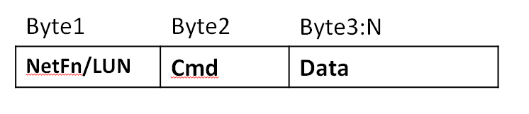
Table 5 Request message byte description
|
Byte name |
Description |
|
LUN |
Sub-address of different LUNs behind the same physical interface, 2 bits in length. |
|
NetFn |
Network function code, which occupies the most significant six bits in the first message byte. An even NetFn code value is used for requests to BMC, and an odd NetFn code value resides in the responses from BMC. |
|
Cmd |
Message byte that specifies the operation to execute under the specified network function. |
|
Data |
Zero or more bytes of data required by a given command. The convention is typically to first pass data LS-byte. However, the implementation varies by command specification. |
BMC-KCS interface response message format
Response messages are data from BMC to the system software through the KCS interface. BMC returns responses through the KCS interface only when data needs to be returned. The message bytes are organized as shown in Figure 2.
Figure 2 BMC-KCS interface response message format
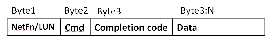
Table 6 Response message format description
|
Byte name |
Description |
|
LUN |
LUN that was passed in the request message. |
|
NetFn |
NetFn code. An odd NetFn value is returned. |
|
Cmd |
Cmd code that was passed in the request message. |
|
Completion code |
Indicates whether the request message is completed successfully. |
|
Data |
Zero or more bytes of data. BMC always returns a response to acknowledge the request, no matter whether it returns data. |
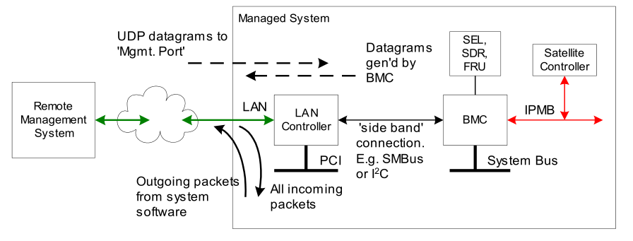
LAN interface
The LAN interface specifications define how to transmit IPMI messages to BMC encapsulated in Remote Management Control Protocol (RMCP) packet datagrams, which is also referred to as IPMI over LAN. IPMI also defines related LAN-specific configuration interfaces for setting other option settings such as IP addresses, and commands for discovering IPMI-based systems.
Figure 3 IPMI LAN interface architecture
The Distributed Management Task Force (DMTF) specifies the RMCP format. This packet format is used for publication through the DMTF's Alert Standard Forum (ASF) specification. The use of the RMCP packet format enables standardized operations between management applications.
IPMI v2.0 defines extended packet formats and functions, which are collectively referred to as RMCP+. RMCP+ is defined in the IPMI-specific part of an RMCP packet. The authentication algorithms used by RMCP+ are more closely to the mechanisms of the ASF 2.0 specification. In addition, RMCP+ provides data confidentiality (encryption) and the payload capability
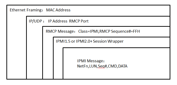
For LAN transmission, IPMI messages are a special data format encapsulated in IPMI session packets. IPMI session packets are encapsulated in RMCP packets, and RCMP packets are encapsulated in UDP datagrams, as shown in Figure 4.
In RMCP/ASF network transmission, the order with the most-significant byte first is applied. The IPMI specification defines that the order with the least-significant byte first is used for transmitting multi-byte numeric fields. Unless otherwise specified, the order with the least-significant byte first is applied to transmit data in the IPMI session header and IPMI message fields.
Figure 4 RMCP+ packet encapsulation
IPMItool
IPMItool is a system command line tool compatible with IPMI 1.5 and IPMI 2.0 standards. The KCS-based IPMItool must operate in the OS of the server, and the LAN-based IPMItool can remotely manage the server.
The IPMItool third-party tool supports Windows and Linux.
Command format
An IPMI command uses the ipmitool -I connect_type -H hostname -U username -P password <command> format, where:
· -I connect_type—Specifies the connection method used to access the device to be managed. The connect_type argument is fixed to lanplus, which indicates that the device to be managed will be accessed as required in the IPMI 2.0 specification.
· -H hostname—Specifies the IP address of the device to be managed.
· -U username—Specifies the HDM username of the device to be managed.
· -P password—Specifies the HDM password of the device to be managed.
· <command>—Specifies the action to be taken. This argument can be a string (chassis status for example) or a hexadecimal raw code (raw 0x00 0x01). For more information about this argument, see H3C HDM IPMI Basics Command Reference.
· -L—Specifies the user role. The default user role is Administrator.
Features
Table 7 lists the features provided by IPMItool.
|
Keyword |
Description |
|
raw |
Send a RAW IPMI request and print response. |
|
i2c |
Send an I2C Master Write-Read command and print response. |
|
spd |
Print SPD info from remote I2C device. |
|
lan |
Configure LAN channels. |
|
chassis |
Get chassis status and set power status. |
|
power |
Shortcut to chassis power commands. |
|
event |
Send predefined events to MC. |
|
mc |
Management Controller status and global enables. |
|
sdr |
Print Sensor Data Repository entries and readings. |
|
sensor |
Print detailed sensor information. |
|
fru |
Print built-in FRU and scan SDR for FRU locators. |
|
gendev |
Read/Write Device associated with Generic Device locators sdr. |
|
sel |
Print system event log (SEL). |
|
pef |
Configure platform event filtering (PEF). |
|
sol |
Configure and connect IPMI v2.0 Serial-over-LAN. |
|
tsol |
Configure and connect with Tyan IPMI v1.5 Serial-over-LAN. |
|
isol |
Configure IPMI v1.5 Serial-over-LAN. |
|
user |
Configure Management Controller users. |
|
channel |
Configure Management Controller channels. |
|
session |
Print session information. |
|
firewall |
Configure firmware firewall. |
|
exec |
Run list of commands from file. |
|
set |
Set runtime variable for shell and exec. |
|
ekanalyzer |
Run FRU-Ekeying analyzer using FRU files. |
IPMItool examples
Example 1: Out-of-band method
# Obtain the value and health status of each sensor on the server through the out-of-band LAN channel.
COMMAND>ipmitool -I lanplus -H 192.168.50.166 -U admin -P Password@_ sdr
18-P/S 1 Zone | 39 degrees C | ok
19-P/S 2 Zone | 36 degrees C | ok
24-BMC Zone | 44 degrees C | ok
32-Outlet_Temp 1 | 45 degrees C | ok
33-Outlet_Temp 2 | 41 degrees C | ok
16-P/S 1 | 36 degrees C | ok
17-P/S 2 | 36 degrees C | ok
02-CPU 1 | 52 degrees C | ok
03-CPU 2 | 51 degrees C | ok
04-CPU 1 DTS | -40 degrees C | ok
05-CPU 2 DTS | -41 degrees C | ok
06-P1 DIMM Ch1-3 | 36 degrees C | ok
Example 2: Inband method
# Obtain FRU information of the server through the inband LPC channel.
[root@localhost~]# ipmitool fru
FRU Device Description : Builtin FRU Device (ID 0)
Chassis Type : Rack Mount Chassis
Chassis Part Number : 0200A00R
Chassis Serial : 750124
Chassis Extra : User Defined
Chassis Extra : 307BACC120AA
Chassis Extra : 6
Chassis Extra : FC9612PW11
Board Mfg Date : Fri Dec 8 00:00:00 2017
Board Mfg : H3C
Board Product : RS33M2C3S
Board Serial : 02A3TWH17C000085
Board Part Number : 0302A3TW
Board Extra : 210235A2CVH17C000003
Product Manufacturer : Unis Huashan Technologies Co., Ltd.
Product Name : 750124
Product Part Number : 0200A00R
Product Version : VERA
Product Serial : 638889
Product Asset Tag : h3c123456789
FRU Device Description : BackPanel1 (ID 2)
Board Mfg Date : Thu Sep 14 00:00:00 2017
Board Mfg : H3C
Board Product : RS33B04LA
Board Serial : 02A3GPH179000133
Board Part Number : 0302A3GP
Board Extra : 02A3GPH179000133
FRU Device Description : MB BIOS (ID 22)
Product Manufacturer : H3C
Product Name : BIOS
Product Part Number : C35
Product Version : 2.00.32P04
FRU Device Description : MB BMC (ID 21)
Product Manufacturer : H3C
Product Name : BMC
Product Part Number : HDM
Product Version : 2.13.00
FRU Device Description : Riser1 (ID 16)
Board Mfg Date : Sun Aug 13 08:00:00 2017
Board Mfg : H3C
Board Product : RS33RGPX16
Board Serial : 02A3H9H178000022
Board Part Number : 0302A3H9
Board Extra : 02A3H9H178000022
FRU Device Description : mLOM (ID 3)
Board Mfg Date : Tue Dec 5 00:00:00 2017
Board Mfg : H3C
Board Product : RS33NGT4M
Board Serial : 02A3GKH17B000267
Board Part Number : 0302A3GK
Board Extra : 02A3GKH17B000267
HDM IPMI implementation
H3C BMC management software, HDM, is compatible with IPMI 1.5 and IPMI 2.0 standards. It can effectively manage a server by using a third-party tool, such as IPMItool, through the LPC- or eSPI-based KCS or LAN-based UDP or IP.
· If LPC-based KCS is used, the third-party tool must operate in the OS of the server.
· If LAN-based UDP or IP is used, the third-party tool can remotely manage the server.
HDM supports using the AES-CBC-128 algorithm for encryption and using the HMAC-SHA1 or HMAC-SHA256 algorithm for authentication and integrity checking.
IPMI standard commands
Table 8 lists standard IPMI Spec commands.
Table 8 HDM IPMI Spec standard commands
|
NetFn |
CMD |
Command description |
HDM support |
|
App |
01h |
Get Device ID |
Yes |
|
App |
01h |
Broadcast 'Get Device ID' |
No |
|
App |
02h |
Cold Reset |
Yes |
|
App |
03h |
Warm Reset |
Yes |
|
App |
04h |
Get Self Test Results |
Yes |
|
App |
05h |
Manufacturing Test On |
Yes |
|
App |
06h |
Set ACPI Power State |
Yes |
|
App |
07h |
Get ACPI Power State |
Yes |
|
App |
08h |
Get Device GUID |
Yes |
|
App |
09h |
Get NetFn Support |
Yes |
|
App |
0Ah |
Get Command Support |
Yes |
|
App |
0Bh |
Get Command Sub-function Support |
Yes |
|
App |
0Ch |
Get Configurable Commands |
Yes |
|
App |
0Dh |
Get Configurable Command Sub-functions |
Yes |
|
App |
60h |
Set Command Enables |
Yes |
|
App |
61h |
Get Command Enables |
Yes |
|
App |
62h |
Set Command Sub-function Enables |
Yes |
|
App |
63h |
Get Command Sub-function Enables |
Yes |
|
App |
64h |
Get OEM NetFn IANA Support |
Yes |
|
App |
22h |
Reset Watchdog Timer |
Yes |
|
App |
24h |
Set Watchdog Timer |
Yes |
|
App |
25h |
Get Watchdog Timer |
Yes |
|
App |
2Eh |
Set BMC Global Enables |
Yes |
|
App |
2Fh |
Get BMC Global Enables |
Yes |
|
App |
30h |
Clear Message Flags |
Yes |
|
App |
31h |
Get Message Flags |
Yes |
|
App |
32h |
Enable Message Channel Receive |
Yes |
|
App |
33h |
Get Message |
Yes |
|
App |
34h |
Send Message |
Yes |
|
App |
35h |
Read Event Message Buffer |
Yes |
|
App |
36h |
Get BT Interface Capabilities |
Yes |
|
App |
37h |
Get System GUID |
Yes |
|
App |
38h |
Get Channel Authentication Capabilities |
Yes |
|
App |
39h |
Get Session Challenge |
Yes |
|
App |
3Ah |
Activate Session |
Yes |
|
App |
3Bh |
Set Session Privilege Level |
Yes |
|
App |
3Ch |
Close Session |
Yes |
|
App |
3Dh |
Get Session Info |
Yes |
|
App |
3Fh |
Get AuthCode |
Yes |
|
App |
40h |
Set Channel Access |
Yes |
|
App |
41h |
Get Channel Access |
Yes |
|
App |
42h |
Get Channel Info Command |
Yes |
|
App |
43h |
Set User Access Command |
Yes |
|
App |
44h |
Get User Access Command |
Yes |
|
App |
45h |
Set User Name |
Yes |
|
App |
46h |
Get User Name Command |
Yes |
|
App |
47h |
Set User Password Command |
Yes |
|
App |
48h |
Activate Payload |
Yes |
|
App |
49h |
Deactivate Payload |
Yes |
|
App |
4Ah |
Get Payload Activation Status |
Yes |
|
App |
4Bh |
Get Payload Instance Info |
Yes |
|
App |
4Ch |
Set User Payload Access |
Yes |
|
App |
4Dh |
Get User Payload Access |
Yes |
|
App |
4Eh |
Get Channel Payload Support |
Yes |
|
App |
4Fh |
Get Channel Payload Version |
Yes |
|
App |
50h |
Get Channel OEM Payload Info |
Yes |
|
App |
52h |
Master Write-Read |
No |
|
App |
54h |
Get Channel Cipher Suites |
Yes |
|
App |
55h |
Suspend/Resume Payload Encryption |
Yes |
|
App |
56h |
Set Channel Security Keys |
Yes |
|
App |
57h |
Get System Interface Capabilities |
Yes |
|
App |
58h |
Set System Info Parameters |
Yes |
|
App |
59h |
Get System Info Parameters |
Yes |
|
App |
60h-64h |
Firmware Firewall Configuration |
No |
|
Chassis |
00h |
Get Chassis Capabilities |
Yes |
|
Chassis |
01h |
Get Chassis Status |
Yes |
|
Chassis |
02h |
Chassis Control |
Yes |
|
Chassis |
03h |
Chassis Reset |
No |
|
Chassis |
04h |
Chassis Identify |
Yes |
|
Chassis |
05h |
Set Chassis Capabilities |
Yes |
|
Chassis |
06h |
Set Power Restore Policy |
Yes |
|
Chassis |
07h |
Get System Restart Cause |
Yes |
|
Chassis |
08h |
Set System Boot Options |
Yes |
|
Chassis |
09h |
Get System Boot Options |
Yes |
|
Chassis |
0Ah |
Set Front Panel Button Enables |
Yes |
|
Chassis |
0Bh |
Set Power Cycle Interval |
Yes |
|
Chassis |
0Fh |
Get POH Counter |
Yes |
|
S/E |
00h |
Set Event Receiver |
Yes |
|
S/E |
01h |
Get Event Receiver |
Yes |
|
S/E |
02h |
Platform Event (a.k.a. "Event Message") |
Yes |
|
S/E |
10h |
Get PEF Capabilities |
Yes |
|
S/E |
11h |
Arm PEF Postpone Timer |
Yes |
|
S/E |
12h |
Set PEF Configuration Parameters |
Yes |
|
S/E |
13h |
Get PEF Configuration Parameters |
Yes |
|
S/E |
14h |
Set Last Processed Event ID |
Yes |
|
S/E |
15h |
Get Last Processed Event ID |
Yes |
|
S/E |
16h |
Alert Immediate |
Yes |
|
S/E |
17h |
PET Acknowledge |
Yes |
|
S/E |
20h |
Get Device SDR Info |
Yes |
|
S/E |
21h |
Get Device SDR |
Yes |
|
S/E |
22h |
Reserve Device SDR Repository |
Yes |
|
S/E |
23h |
Get Sensor Reading Factors |
Yes |
|
S/E |
24h |
Set Sensor Hysteresis |
Yes |
|
S/E |
25h |
Get Sensor Hysteresis |
Yes |
|
S/E |
26h |
Set Sensor Threshold |
Yes |
|
S/E |
27h |
Get Sensor Threshold |
Yes |
|
S/E |
28h |
Set Sensor Event Enable |
Yes |
|
S/E |
29h |
Get Sensor Event Enable |
No |
|
S/E |
2Ah |
Re-arm Sensor Events |
No |
|
S/E |
2Bh |
Get Sensor Event Status |
No |
|
S/E |
2Dh |
Get Sensor Reading |
Yes |
|
S/E |
2Eh |
Set Sensor Type |
Yes |
|
S/E |
2Fh |
Get Sensor Type |
Yes |
|
S/E |
30h |
Set Sensor Reading And Event Status |
Yes |
|
Storage |
10h |
Get FRU Inventory Area Info |
Yes |
|
Storage |
11h |
Read FRU Data |
Yes |
|
Storage |
12h |
Write FRU Data |
Yes |
|
Storage |
20h |
Get SDR Repository Info |
Yes |
|
Storage |
21h |
Get SDR Repository Allocation Info |
Yes |
|
Storage |
22h |
Reserve SDR Repository |
Yes |
|
Storage |
23h |
Get SDR |
Yes |
|
Storage |
24h |
Add SDR |
Yes |
|
Storage |
25h |
Partial Add SDR |
Yes |
|
Storage |
26h |
Delete SDR |
Yes |
|
Storage |
27h |
Clear SDR Repository |
Yes |
|
Storage |
28h |
Get SDR Repository Time |
Yes |
|
Storage |
29h |
Set SDR Repository Time |
Yes |
|
Storage |
2Ah |
Enter SDR Repository Update Mode |
Yes |
|
Storage |
2Bh |
Exit SDR Repository Update Mode |
Yes |
|
Storage |
2Ch |
Run Initialization Agent |
Yes |
|
Storage |
40h |
Get SEL Info |
Yes |
|
Storage |
41h |
Get SEL Allocation Info |
Yes |
|
Storage |
42h |
Reserve SEL |
Yes |
|
Storage |
43h |
Get SEL Entry |
Yes |
|
Storage |
44h |
Add SEL Entry |
Yes |
|
Storage |
45h |
Partial Add SEL Entry |
Yes |
|
Storage |
46h |
Delete SEL Entry |
Yes |
|
Storage |
47h |
Clear SEL |
Yes |
|
Storage |
48h |
Get SEL Time |
Yes |
|
Storage |
49h |
Set SEL Time |
Yes |
|
Storage |
5Ah |
Get Auxiliary Log Status |
Yes |
|
Storage |
5Bh |
Set Auxiliary Log Status |
Yes |
|
Storage |
5Ch |
Get SEL Time UTC Offset |
Yes |
|
Storage |
5Dh |
Set SEL Time UTC Offset |
Yes |
|
Transport |
01h |
Set LAN Configuration Parameters |
Yes |
|
Transport |
02h |
Get LAN Configuration Parameters |
Yes |
|
Transport |
03h |
Suspend BMC ARPs |
Yes |
|
Transport |
04h |
Get IP/UDP/RMCP Statistics |
No |
|
Transport |
10h |
Set Serial/Modem Configuration |
Yes |
|
Transport |
11h |
Get Serial/Modem Configuration |
Yes |
|
Transport |
12h |
Set Serial/Modem Mux |
Yes |
|
Transport |
13h |
Get TAP Response Codes |
Yes |
|
Transport |
14h |
Set PPP UDP Proxy Transmit Data |
No |
|
Transport |
15h |
Get PPP UDP Proxy Transmit Data |
No |
|
Transport |
16h |
Send PPP UDP Proxy Packet |
No |
|
Transport |
17h |
Get PPP UDP Proxy Receive Data |
No |
|
Transport |
18h |
Serial/Modem Connection Active |
No |
|
Transport |
19h |
Callback |
Yes |
|
Transport |
1Ah |
Set User Callback Options |
Yes |
|
Transport |
1Bh |
Get User Callback Options |
Yes |
|
Transport |
1Ch |
Set Serial Routing Mux |
No |
|
Transport |
20h |
SOL Activating |
No |
|
Transport |
21h |
Set SOL Configuration Parameters |
Yes |
|
Transport |
22h |
Get SOL Configuration Parameters |
Yes |
|
Transport |
30h |
Forwarded Command |
No |
|
Transport |
31h |
Set Forwarded Commands |
No |
|
Transport |
32h |
Get Forwarded Commands |
No |
|
Transport |
33h |
Enable Forwarded Commands |
No |
|
Bridge |
00h |
Get Bridge State |
No |
|
Bridge |
01h |
Set Bridge State |
No |
|
Bridge |
02h |
Get ICMB Address |
No |
|
Bridge |
03h |
Set ICMB Address |
No |
|
Bridge |
04h |
Set Bridge ProxyAddress |
No |
|
Bridge |
05h |
Get Bridge Statistics |
No |
|
Bridge |
06h |
Get ICMB Capabilities |
No |
|
Bridge |
08h |
Clear Bridge Statistics |
No |
|
Bridge |
09h |
Get Bridge Proxy Address |
No |
|
Bridge |
0Ah |
Get ICMB Connector Info |
No |
|
Bridge |
0Bh |
Get ICMB Connection ID |
No |
|
Bridge |
0Ch |
Send ICMB Connection ID |
No |
|
Bridge |
10h |
PrepareForDiscovery |
No |
|
Bridge |
11h |
GetAddresses |
No |
|
Bridge |
12h |
SetDiscovered |
No |
|
Bridge |
13h |
GetChassisDeviceId |
No |
|
Bridge |
14h |
SetChassisDeviceId |
No |
|
Bridge |
20h |
BridgeRequest |
No |
|
Bridge |
21h |
BridgeMessage |
No |
|
Bridge |
30h |
GetEventCount |
No |
|
Bridge |
31h |
SetEventDestination |
No |
|
Bridge |
32h |
SetEventReceptionState |
No |
|
Bridge |
33h |
SendICMBEventMessage |
No |
|
Bridge |
34h |
GetEventDestination (optional) |
No |
|
Bridge |
35h |
GetEventReceptionState (optional) |
No |
Table 9 lists standard IPMI NetFn values.
|
NetFn |
Value |
|
App |
0x06 |
|
Chassis |
0x00 |
|
S/E |
0x04 |
|
Storage |
0x0A |
|
Transport |
0x0C |
|
Bridge |
0x02 |
|
|
NOTE: For more information about the command details, see the IPMI2.0 specification. |
IPMI extended commands
In addition to standard IPMI commands, HDM also supports IPMI extended command set by using commands in raw format to meet the increasing requirements of data center users.
Table 8 lists the main IPMI features. For more information about IPMI extended commands, see H3C HDM IPMI Basics Command Reference.
Table 10 HDM IPMI extended features
|
Feature |
Description |
|
Hardware |
Obtains hardware information about CPUs, memory, and PCIe modules. |
|
Storage management |
Manages storage controllers, physical drives, and logical drives. |
|
BIOS |
Manages part of BIOS configuration items through commands. |
|
DNS |
Configures DNS settings and obtains DNS information. |
|
Firewall |
Configures firewall settings and obtains firewall information. |
|
Network port |
Manages network ports, including bond mode configuration and network port status configuration. |
|
Directory service |
Configures LDAP and AD settings. |
|
SNMP |
Configures SNMP settings and obtains SNMP information. |
|
NTP |
Configures NTP settings and obtains NTP information. |
|
HDM maintenance |
Manages firmware and HDM configuration. |
|
Maintainability |
Configures syslog and SMTP services, obtains syslog and SMTP information, and manages SEL settings. |
|
Fan |
Manages fans. |
|
PSU |
Manages power supplies. |
|
KVM |
Configures KVM encryption settings. |
Interface privileges
HDM assigns a permitted module for each IPMI interface. When an interface is used, HDM will identify the privileges according to the configuration of the module to which the interface belongs and the user role group configuration. Thus, this improves the security of the interface.
Table 11 Privileges of HDM modules
|
Module |
Description |
|
User accounts |
Includes user management, password policy configuration, directory management, configuration import and export, and unified control. |
|
Basic configuration |
Includes network confirmation, alarm configuration, and asset tag configuration. |
|
Remote control |
Includes management of RAID, BIOS options, boot options, UID LEDs, and SOL connection. |
|
Remote media |
Includes remote media mounting. |
|
Security |
Includes SLL, firewall, and access service configuration. |
|
Power control |
Includes power supply management, fan management, and processor power states configuration. |
|
Maintenance |
Includes log management, video recording and screenshots, firmware management, and firmware restart. |
|
Password modification |
Includes modification of the current user's password. |
|
Information query |
Supported typically on the GET interface. |
Acronyms
|
Acronym |
Full name |
|
IPMI |
Intelligent Platform Management Interface |
|
HDM |
Hardware Device Management |
|
BMC |
Baseboard Management Controller |
|
MC |
Management Controller |
|
IPMB |
Intelligent Platform Management Bus |
|
DMTF |
Distributed Management Task Force |
|
KVM |
Keyboard, Video, and Mouse |
|
SMS |
System Management Software |
|
LUN |
Logical Unit Number |
|
LPC |
Low Pin Count |
|
KCS |
Keyboard Controller Style |
|
ASF |
Apache Software Foundation |
|
DCMI |
Data Centers Manageability Interface |
