- Table of Contents
- Related Documents
-
| Title | Size | Download |
|---|---|---|
| 01-Text | 18.55 MB |
Entering the BIOS setup utility
Setting the BIOS setup mode (for all servers except for the B5700, B5800, and B7800)
Displaying processor information
Displaying onboard drive information (for all servers except for the R8900)
Displaying HDM network information
Setting HDM network information (for all servers except for the B5700, B5800, and B7800)
Restrictions and guidelines for configuring BIOS passwords
Setting the administrator password
Setting the system date and time
Restoring BIOS default settings
Configuring an iSCSI virtual driver (for the R5300, B5700, B5800, and B7800 servers)
Serial Port Console Redirection submenu
PCI Subsystem Settings submenu
Network Stack Configuration submenu
iSCSI Configuration submenu (for the R5300, B5700, B5800, and B7800 servers)
Intel(R) VROC sSATA Controller submenu (for all servers except for the R8900)
Intel(R) Virtual RAID on CPU submenu
Intel(R) Optane(TM) DC Persistent Memory Configuration submenu
Miscellaneous Configuration submenu
Server ME Configuration submenu
Processor Configuration submenu
Common RefCode Configuration submenu
About the BIOS
Introduction
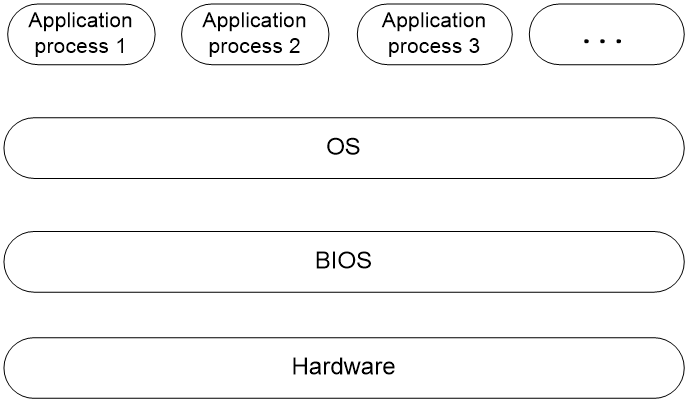
The Basic Input and Output System (BIOS) is a non-volatile firmware stored in the system ROM of a server. It is used to perform hardware initialization during server booting and provide runtime services for the operating systems. As shown in Figure 1, the BIOS interacts between the server hardware and the operating system (OS).
Figure 1 Layered architecture of a server system
Applicable products
This document is applicable to the following products:
· H3C UniServer E3200 G3 server
· H3C UniServer R2700 G3 server
· H3C UniServer R2900 G3 server
· H3C UniServer R4300 G3 server
· H3C UniServer R4400 G3 server
· H3C UniServer R4700 G3 server
· H3C UniServer R4900 G3 server
· H3C UniServer R5300 G3 server
· H3C UniServer R6700 G3 server
· H3C UniServer R6900 G3 server
· H3C UniServer R8900 G3 server
· H3C UniServer B5700 G3 blade server
· H3C UniServer B5800 G3 blade server
· H3C UniServer B7800 G3 blade server
Using this document
The information in this document is subject to change over time. You can access the H3C website to obtain the most recent version of the BIOS.
The information in this document might differ from your product if it contains custom configuration options or features.
The figures used in this document are for illustration only and might differ from your product.
Common BIOS tasks
This section provides procedures for the following common BIOS tasks:
· Entering the BIOS setup utility
· Setting the BIOS setup mode (for all servers except for the B5700, B5800, and B7800)
· Displaying processor information
· Displaying memory information
· Displaying onboard drive information (for all servers except for the R8900)
· Displaying HDM network information
· Setting HDM network information (for all servers except for the B5700, B5800, and B7800)
· Setting the system date and time
· Setting the server boot order
· Restoring BIOS default settings
· Configuring an iSCSI virtual driver (for the R5300, B5700, B5800, and B7800 servers)
Entering the BIOS setup utility
1. Connect a keyboard, mouse, and monitor to the server or enable the remote console from the HDM Web interface.
For information about enabling the remote console, see HDM online help.
2. Start or restart the server.
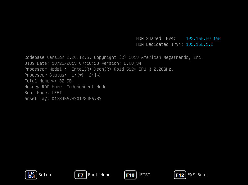
3. Press Del or Esc when the BIOS startup screen opens, as shown in Figure 2.
The HDM Dedicated IPv4 item is unavailable for the B5700, B5800, and B7800 servers.
4. Enter the BIOS password if required during boot-up, as shown in Figure 3.
By default, no BIOS passwords are set. For information about BIOS password setup, see "Configuring BIOS passwords."
If only the administrator password is set, enter the administrator password to obtain the administrator privileges or press Enter to obtain the user privileges.
If you enter an incorrect password for three consecutive times, the server will restart automatically.
If you forget the password, use the system maintenance switch in the server to clear BIOS password settings. For more information about the system maintenance switch, see the user guide for the server.
|
|
IMPORTANT: If you use the system maintenance switch to clear BIOS passwords, restore the switch to the default position after you set new password settings. If you fail to do so, the new settings will be cleared. |
Figure 3 Entering the BIOS password

5. On the BIOS setup utility screen that opens, follow the instructions at the lower-right side of the screen to configure BIOS settings, as shown in Figure 4.
Table 1 shows detailed information about the operation keys.
Figure 4 BIOS setup utility screen

|
Key |
Description |
|
→← |
Select a screen. |
|
↑↓ |
Select an item or a submenu. |
|
Enter |
Select an item to edit its value or access a submenu. |
|
+/- |
Change the field value of the selected item. |
|
ESC |
Exit the BIOS setup utility or return to the previous screen. |
|
F1 |
Display the general help window. |
|
F2 |
Load previous values in the BIOS. |
|
F3 |
Load default values in the BIOS. |
|
F4 |
Save the current configuration and exit the BIOS. |
|
<K> |
Scroll up the help area at the upper-right side of the screen. |
|
<M> |
Scroll down the help area at the upper-right side of the screen. |
Setting the BIOS setup mode (for all servers except for the B5700, B5800, and B7800)
1. Enter the BIOS setup utility. For more information, see "Entering the BIOS setup utility."
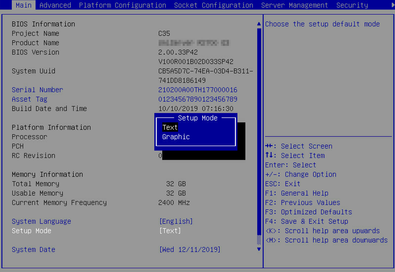
2. Select Main > Setup Mode, and press Enter.
3. In the Setup Mode window that opens, select a BIOS setup mode (Text or Graphic), and press Enter.
Figure 5 Setting the BIOS setup mode
4. Press F4 and then press Enter to save the configuration.
The server will restart automatically.
Displaying processor information
1. Enter the BIOS setup utility. For more information, see "Entering the BIOS setup utility."
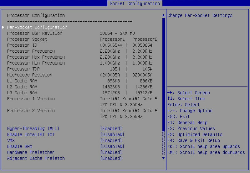
2. Select Socket Configuration > Processor Configuration, and press Enter.
The Processor Configuration submenu that opens displays detailed information about processors, as shown in Figure 6.
For more information about the Processor Configuration submenu, see "Processor Configuration submenu."
Figure 6 Processor Configuration screen
Displaying memory information
1. Enter the BIOS setup utility. For more information, see "Entering the BIOS setup utility."
2. Select Socket Configuration > Memory Configuration, and press Enter.
The Memory Configuration submenu that opens displays memory capacity and frequency information, as shown in Figure 7.
For more information about the Memory Configuration submenu, see "Memory Configuration submenu."
Figure 7 Memory Configuration submenu

3. To view detailed information about each DIMM, select Memory Topology, and press Enter.
The screen that opens displays detailed information about each DIMM.
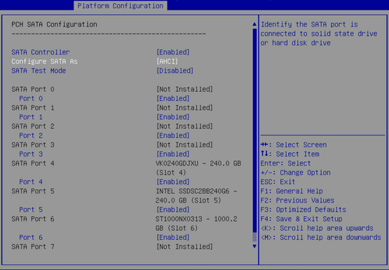
Displaying onboard drive information (for all servers except for the R8900)
About this task
Both the PCH SATA Configuration and PCH sSATA Configuration submenus display onboard drive information. This example uses the PCH SATA Configuration submenu. For more information about the submenus, see "PCH SATA Configuration submenu screen."
Procedure
1. Enter the BIOS setup utility. For more information, see "Entering the BIOS setup utility."
2. Select Platform Configuration > PCH Configuration > PCH SATA Configuration, and press Enter.
The PCH SATA Configuration submenu that opens displays drive information, as shown in Figure 8.
Figure 8 PCH SATA Configuration submenu
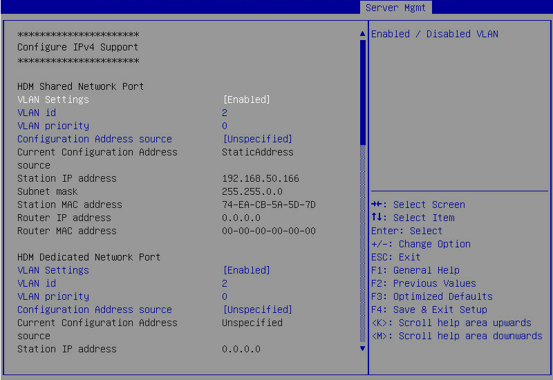
Displaying HDM network information
1. Enter the BIOS setup utility. For more information, see "Entering the BIOS setup utility."
2. Select Server Management > HDM Network Configuration, and press Enter.
The HDM Network Configuration submenu that opens displays HDM network configuration information, as shown in Figure 9.
Figure 9 HDM Network Configuration screen
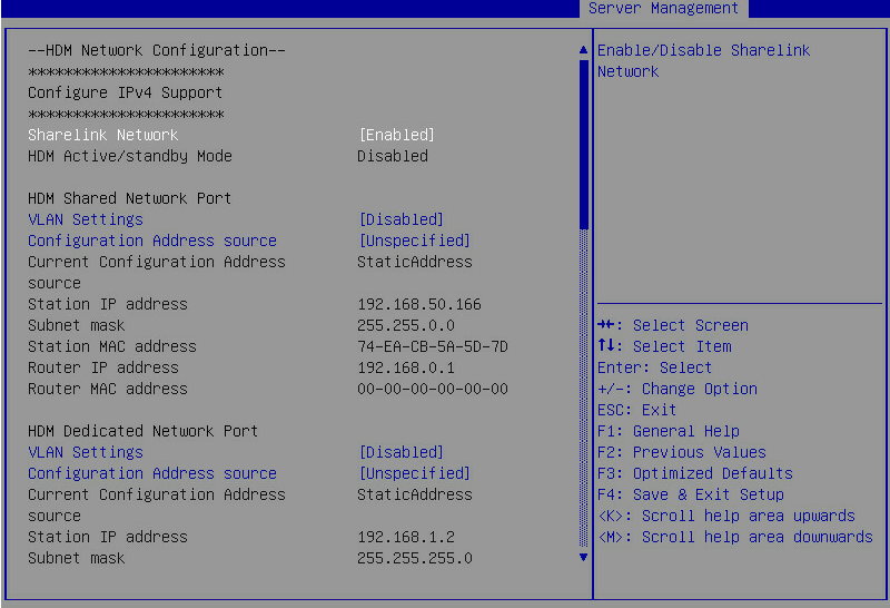
Setting HDM network information (for all servers except for the B5700, B5800, and B7800)
About this task
Perform this task to configure the IP address, subnet mask, and router IP address of HDM network ports and the method of obtaining the network information.
The submenus are the same for both HDM dedicated and shared network ports. This example uses the HDM shared network port.
Restrictions and guidelines
To avoid network storms, make sure the IP address of the HDM shared network port is on a network segment different than the HDM dedicated network port.
Procedure
1. Enter the BIOS setup utility. For more information, see "Entering the BIOS setup utility."
2. Select Server Management > HDM Network Configuration, and press Enter.
The HDM Network Configuration submenu that opens displays HDM network configuration information, as shown in Figure 10.
Figure 10 HDM Network Configuration submenu
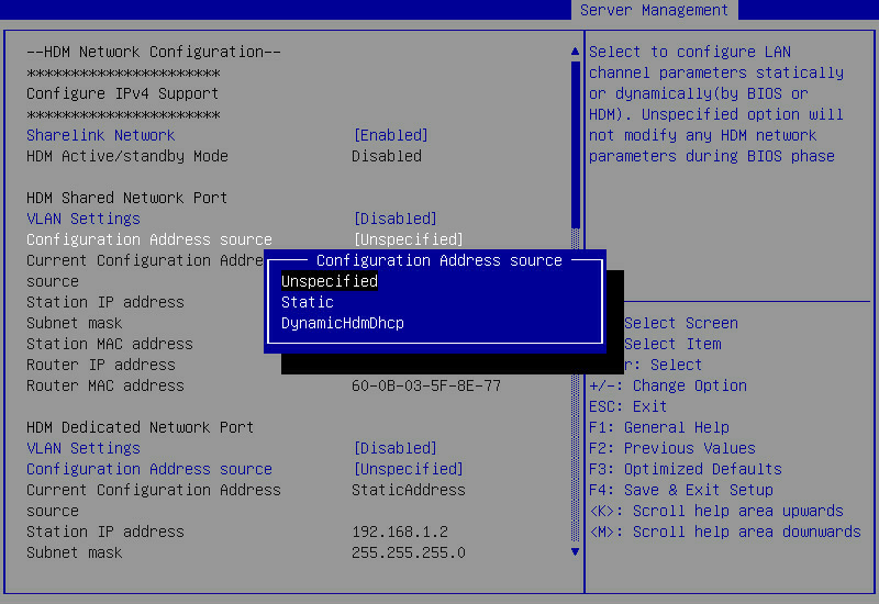
3. Select Configuration Address source for the HDM shared network port, and press Enter.
4. In the dialog box that opens, select the method for obtaining HDM network information. Options are:
¡ Unspecified—Retains current configuration.
¡ Static—Uses manually specified configuration.
¡ DynamicHdmDhcp—Uses network information obtained through DHCP.
Figure 11 Configuration Address Source dialog box
5. Press Enter. If you select Static as the method for obtaining HDM network information, edit the following items and press Enter every time you finish editing:
¡ Station IP address—Enter a static IP address. This item is required.
¡ Subnet mask—Enter a subnet mask for the static IP address. This item is required.
¡ Router IP address—Enter a gateway IP address.
6. Press F4 and then press Enter to save the configuration.
The server will restart automatically.
Configuring BIOS passwords
About this task
BIOS passwords include an administrator password and a user password. By default, no passwords are set.
If only the administrator password is set, you can enter this password to obtain administrator privileges or press Enter to obtain user privileges. The system prompts for the password when you use shortcut keys to enter the BIOS setup utility, iFIST, boot menu, or PXE boot interface.
If only the user password is set, you must enter this password as the power-on password at the startup of the server. To enter the BIOS setup utility, this password is also required and you can obtain administrator privileges.
If both the administrator password and the user password are set, the following rules apply:
· If the two passwords are different, you can enter the administrator password to obtain administrator privileges or enter the user password to obtain user privileges. If the two passwords are the same, you can enter the password to obtain the administrator privileges.
· The system prompts for the user password at BIOS access and prompts for the administrator password when you use shortcut keys to enter the iFIST, boot menu, or PXE boot interface.
Table 2 shows menu items that are accessible in the BIOS when you enter BIOS setup by using the user password.
Table 2 BIOS menu items accessible with the user password
|
Level-1 menu |
Submenu items |
|
|
Security |
User Password |
|
|
Save & Exit |
Save Changes and Exit |
|
|
Discard Changes and Exit |
||
|
Save Changes and Reset |
||
|
Discard Changes and Reset |
||
|
Save Changes |
||
|
Discard Changes |
Restrictions and guidelines for configuring BIOS passwords
To prevent unauthorized access and changes to the BIOS settings, set different BIOS user and BIOS administrator passwords for the server as a best practice.
When you change a BIOS password, make sure the new password is different from the most recent three passwords.
The BIOS passwords must meet the following requirements:
· A case-sensitive string of 8 to 20 characters. Valid characters are letters, digits, spaces, and special characters in Table 3.
· Contain a minimum of two character types from uppercase letters, lowercase letters, and digits.
· Contain a minimum of one space or special character.
|
Character name |
Symbol |
Character name |
Symbol |
|
Back quote |
` |
Tilde |
~ |
|
Exclamation point |
! |
At sign |
@ |
|
Pound sign |
# |
Dollar sign |
$ |
|
Percent sign |
% |
Caret |
^ |
|
Ampersand sign |
& |
Asterisk |
* |
|
Left parenthesis |
( |
Right parenthesis |
) |
|
Underscore |
_ |
Plus sign |
+ |
|
Minus sign |
- |
Equal sign |
= |
|
Left bracket |
[ |
Right bracket |
] |
|
Back slash |
\ |
Left brace |
{ |
|
Right brace |
} |
Vertical bar |
| |
|
Semi-colon |
; |
Apostrophe |
' |
|
Colon |
: |
Quotation marks |
" |
|
Comma |
, |
Dot |
. |
|
Forward slash |
/ |
Left angle bracket |
< |
|
Right angle bracket |
> |
Question mark |
? |
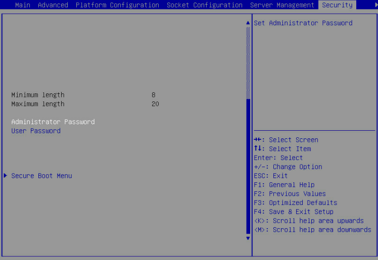
Setting the administrator password
1. Enter the BIOS setup utility. For more information, see "Entering the BIOS setup utility."
2. Select Security > Administrator Password, and press Enter.
Figure 12 Setting the administrator password
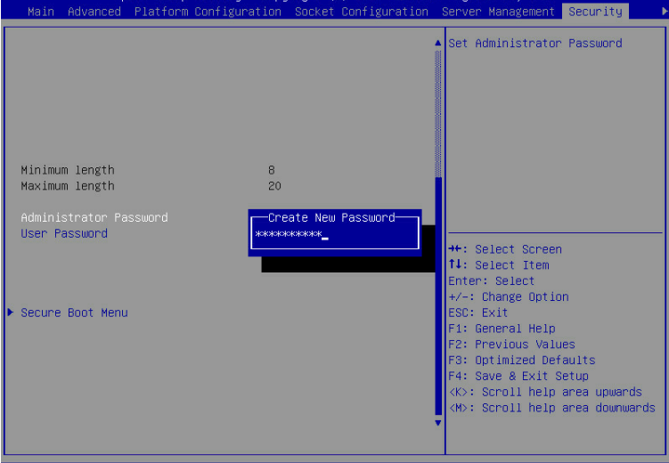
3. In the Create New Password dialog box that opens, enter an administrator password, and press Enter.
Figure 13 Creating an administrator password
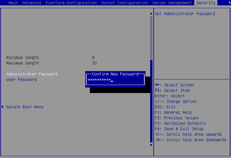
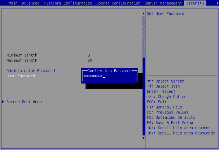
4. In the Confirm New Password dialog box that opens, enter the password again, and press Enter.
Figure 14 Confirming the administrator password
5. Press F4 and then press Enter to save the configuration.
The server will restart automatically.
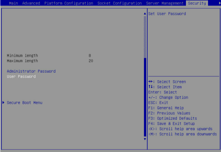
Setting the user password
1. Enter the BIOS setup utility. For more information, see "Entering the BIOS setup utility."
2. Select Security > User Password, and press Enter.
Figure 15 Setting the user password
3. In the Create New Password dialog box that opens, enter a user password, and press Enter.
Figure 16 Creating a user password

4. In the Confirm New Password dialog box that opens, enter the password again, and press Enter.
Figure 17 Confirming the user password
5. Press F4 and then press Enter to save the configuration.
The server will restart automatically.
Deleting BIOS passwords
About this task
The procedure is the same for deleting the administrator password and the user password. This section uses the administrator password as an example.
Procedure
1. Enter the BIOS setup utility. For more information, see "Entering the BIOS setup utility."
2. Select Security > Administrator Password, and press Enter.
Figure 18 Selecting the administrator password

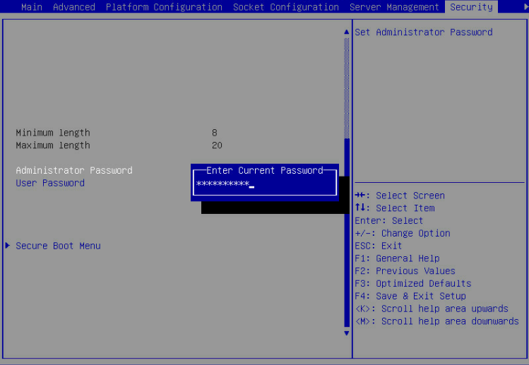
3. In the Enter Current Password dialog box that opens, enter the current administrator password, and press Enter.
Figure 19 Entering the current administrator password
3. Press Enter when the Create New Password dialog box opens as shown in Figure 20.
Figure 20 Deleting the administrator password

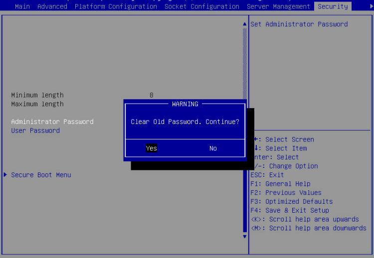
4. In the WARNING dialog box that opens, select Yes, and press Enter.
Figure 21 Confirming the deletion
5. Press F4 and then press Enter to save the configuration.
The server will restart automatically.
Setting the system date and time
1. Enter the BIOS setup utility. For more information, see "Entering the BIOS setup utility."
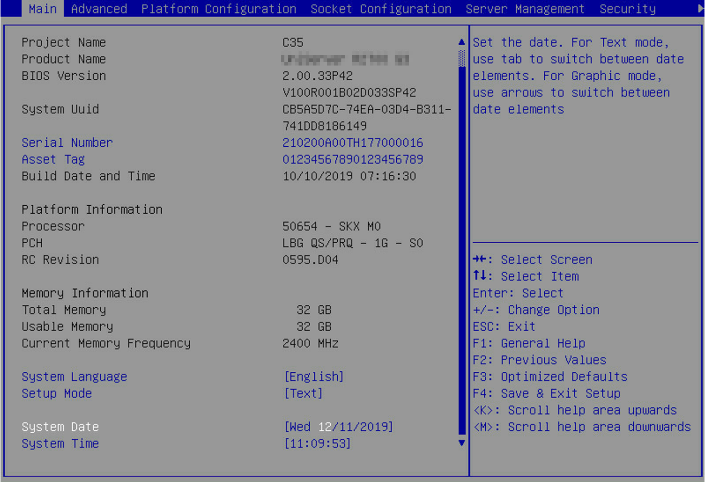
2. Select the Main menu.
Figure 22 Main menu
a. Select System Date.
The system date is in the format of mm/dd/yyyy.
a. Press Enter or Tab to switch between the month, day, and year fields and then use the following methods to modify the value:
- Press + to increase the value by 1.
- Press – to decrease the value by 1.
- Press numeric keys to enter a new value.
a. Select System Time.
The system time uses the 24-hour time system and is in the format of hh:mm:ss.
a. Press Enter or Tab to switch between the hour, minute, and second fields and then use the following methods to modify the value:
- Press + to increase the value by 1.
- Press – to decrease the value by 1.
- Press numeric keys to enter a new value.
5. Press F4 and then press Enter to save the configuration.
The server will restart automatically.
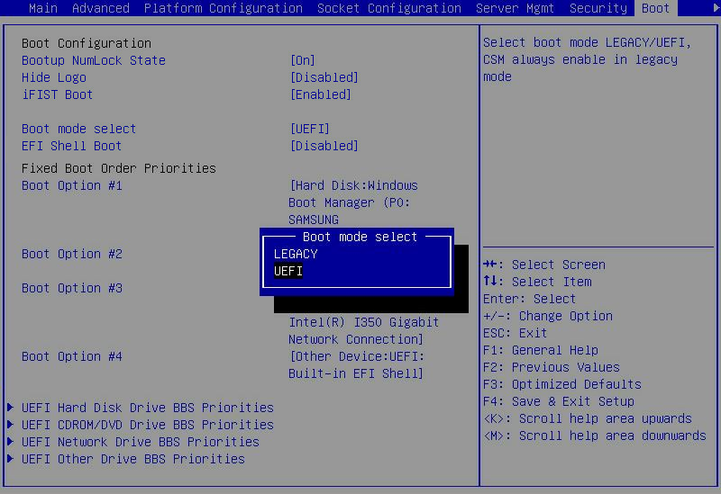
Setting the BIOS boot mode
About this task
The server supports two BIOS boot modes: legacy mode and UEFI mode.
By default, the boot mode is UEFI. For operating systems that support only the legacy mode, change the boot mode to legacy.
Procedure
1. Enter the BIOS setup screen. For more information, see "Entering the BIOS setup utility."
2. Select Boot > Boot mode select, and press Enter.
3. In the Boot mode select dialog box that opens, select LEGACY or UEFI, and press Enter.
Figure 23 Setting the BIOS boot mode
4. Press F4 and then press Enter to save the configuration.
The server will restart automatically.
Setting the server boot order
About this task
Perform this task to change the server boot order.
The default boot order is hard disk > network > CD/DVD > other device as shown in the Fixed Boot Order Priorities list in Figure 24.
Restrictions and guidelines
If the server has more than one boot devices of the same type, the Fixed Boot Order Priorities list displays only the first boot device. To change the first boot device, enter the corresponding priorities submenu of the boot device, and then set the first boot option. For example, to change the first boot option for hard disks, enter the UEFI Hard Disk Drive BBS Priorities submenu as shown in Figure 187, and then set the first boot option.
Procedure
1. Enter the BIOS setup utility. For more information, see "Entering the BIOS setup utility."
2. Select the Boot menu.
Figure 24 Boot menu
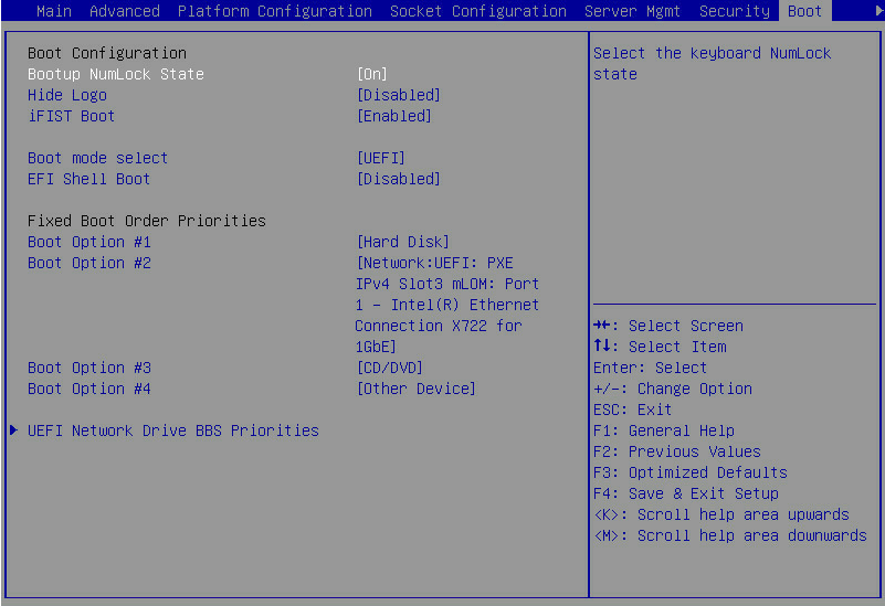
Table 4 Server boot options
|
Item |
Example |
|
Hard Disk |
Disk and USB. |
|
Network |
Network. |
|
CD/DVD |
CD-ROM and DVD-ROM (including virtual ones). |
|
Other Device |
This item is available only in UEFI boot mode. Options: · Embedded UEFI shell. This option is displayed only when EFI Shell Boot is set to Enabled. · USB devices with the capacity less than 32 GB. · Virtual drives. |
|
Disabled |
The boot option is disabled. |
3. Select the option to be modified from the Fixed Boot Order Priorities area, and press Enter.
4. In the dialog box that opens, select a new boot device type, and press Enter.
Figure 25 Changing a boot option
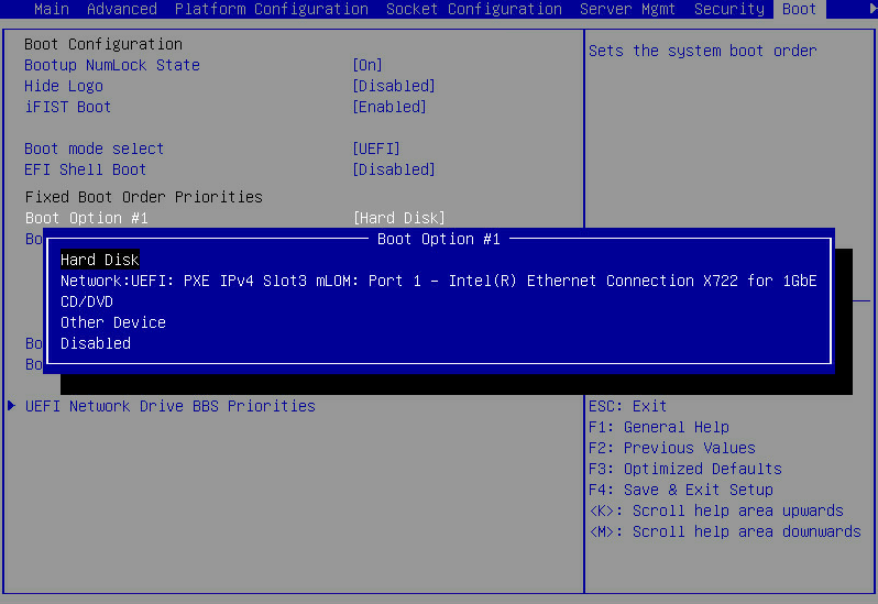
5. Press F4 and then press Enter to save the configuration.
The server will restart automatically.
Configuring RAID
For information about to configure RAID through the BIOS, see the storage controller user guide for the server.
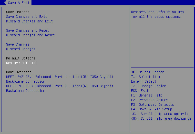
Restoring BIOS default settings
1. Enter the BIOS setup utility. For more information, see "Entering the BIOS setup utility."
2. Press F3 in the BIOS, or select Save & Exit > Restore Defaults and press Enter as shown in Figure 26.
Figure 26 Restoring the default from the Save & Exit menu
Configuring an iSCSI virtual driver (for the R5300, B5700, B5800, and B7800 servers)
About this task
iSCSI provides access to shared storage resources by carrying SCSI commands over TCP/IP networks.
Restrictions and guidelines
If iSCSI is enabled on a network port, PXE is disabled for the port.
Make sure the UEFI boot mode is used for the server. For more information about setting the BIOS boot mode, see "Setting the BIOS boot mode."
Prerequisites
· You have the knowledge of iSCSI and the iSCSI server setup process.
· You have the access to an external iSCSI server running on a supported OS.
· You must prepare iSCSI target parameters. Table 5 shows the required parameters and parameter examples.
Table 5 iSCSI target parameters
|
Item |
Example |
|
iSCSI target name |
iqn.1994-05.com.redhat:cb2b5bd41b30 |
|
iSCSI initiator name |
iqn.1994-05.com.redhat:sq1s1sq11s11 |
|
Logical unit number |
LUN 0 |
|
IP address of the iSCSI server |
192.168.14.200 (IPv4) |
|
Port number |
3260 |
Procedure
1. Enter the BIOS setup utility. For more information, see "Entering the BIOS setup utility."
2. (Optional.) Set the UEFI boot mode of ports on the iSCISI module to a mode other than iSCSI.
For some iSCISI modules, if the UEFI boot mode is iSCSI, the configuration item for the module is unavailable in the iSCSI Configuration menu.
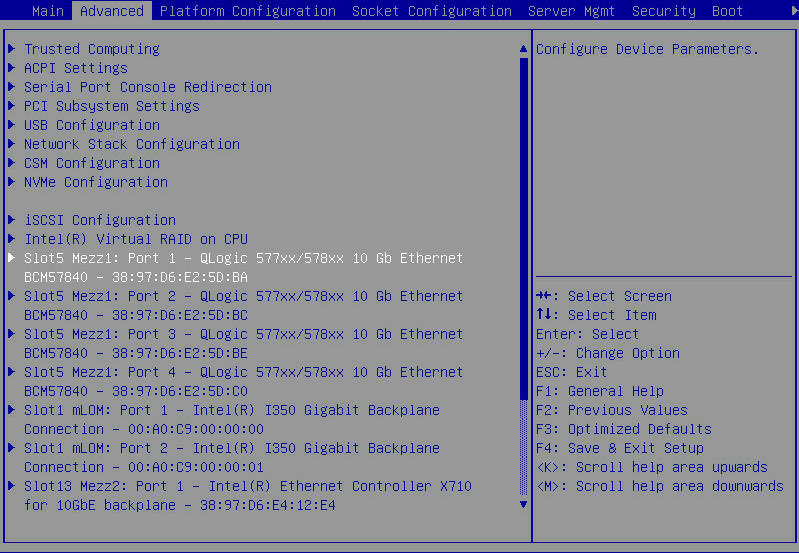
This section uses port Slot 5 Mezz1: Port 1 as an example.
a. Select Advanced > Slot 5 Mezz1: Port 1- Qlogic 577xx/578xx 10 Gb Ethernet BCM57840 – 38:97:D6:E2:5D:BA.
Figure 27 Network port configuration option
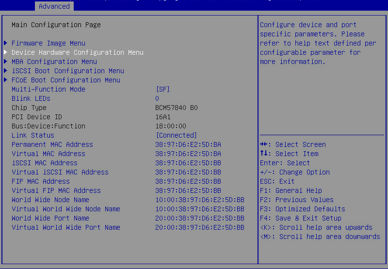
b. Select Device Hardware Configuration Menu, and press Enter.
Figure 28 Device Hardware Configuration Menu
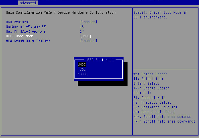
c. Set the UEFI boot mode to UNDI.
Figure 29 Setting the UEFI boot mode of the iSCSI module
d. Save the changes and reboot the server for the configuration changes to take effect.
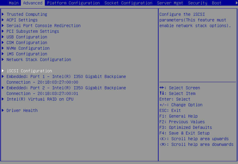
3. Select Advanced > iSCSI Configuration, and press Enter.
4. Select iSCSI Initiator Name, and enter the iSCSI initiator name.
The iSCSI initiator name must be in the iSCSI Qualified Name (IQN) format, iqn.2003-02.emu.com:test123, for example.
Figure 31 Entering the iSCSI initiator name

5. Select Add an Attempt, and press Enter.
6. Select the MAC address of the network port interconnected to the iSCSI server, and press Enter.
Figure 32 Selecting the MAC address of the network port interconnected to the iSCSI server

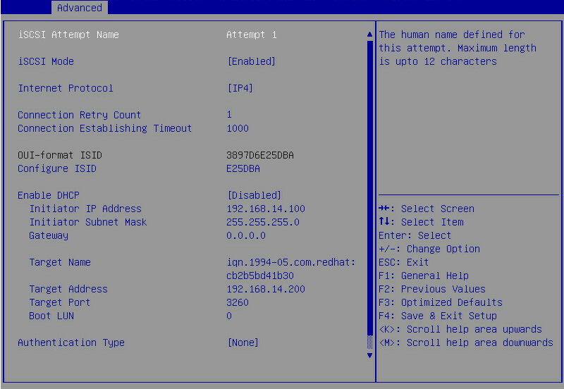
7. Configure an iSCSI virtual driver (iSCSI attempt):
¡ Set the iSCSI mode to Enabled.
¡ Set the internet protocol.
¡ Set the connection retry count and the connection establishing timeout.
¡ Enable or disable DHCP as needed.
If DHCP is disabled, you need to specify the following parameters: Initiator IP address, Initiator Subnet Mask, and Gateway.
¡ Set the target name. The target name must be in the IQN format, for example, iqn.1994-05.com.redhat:cb2b5bd41b30.
¡ Set the target address. The target address is the IP address of the iSCSI server, which is in dotted-decimal notion, for example, 192.168.14.200.
¡ Set the target port. The target port is the port number of the iSCSI server, for example, 3260.
¡ Set the boot LUN. In the Boot LUN dialog box that opens, enter the logical unit number, for example, 0.
Figure 33 Configuring an iSCSI attempt
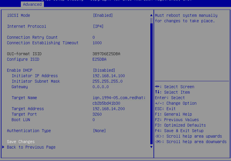
8. Select Save Changes, and press Enter.
Figure 34 Saving the iSCSI attempt configuration
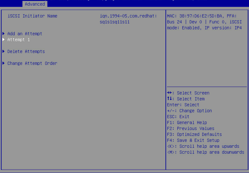
9. Select Back to Previous Page, and press Enter.
The iSCSI Configuration menu that opens displays the newly created iSCSI virtual driver Attempt 1.
Figure 35 Displaying Attempts
BIOS menus
Main menu
As shown in Figure 36, the Main menu contains information about the BIOS, memory, system language, and system time and date. For more information about the menu items, see Table 6.
Figure 36 Main menu screen
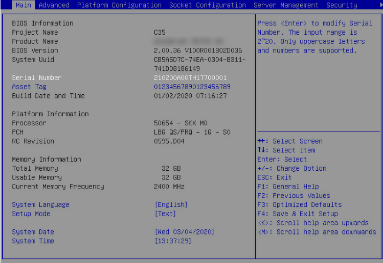
Table 6 Items on the Main menu screen
|
Item |
Description |
Default |
|
BIOS Information |
||
|
Project Name |
Displays the project name. |
N/A |
|
Product Name |
Displays the server model. |
N/A |
|
BIOS Version |
Displays the BIOS version. |
N/A |
|
System Uuid |
Displays the universally unique identifier (UUID) of the system. |
N/A |
|
Serial Number |
Displays the serial number of the server, a string of 2 to 20 characters. Only uppercase letters and digits are allowed. |
N/A |
|
Asset Tag |
Specify the asset tag of the server, a case-sensitive string of 2 to 32 characters. |
N/A |
|
Build Date and Time |
Displays the date and time of the BIOS build. |
N/A |
|
Platform Information |
||
|
Processor |
Displays the CPU ID and stepping. |
N/A |
|
PCH |
Displays the platform controller hub (PCH) model. |
N/A |
|
RC Revision |
Displays the RC version. |
N/A |
|
Memory Information |
||
|
Total Memory |
Displays the total memory capacity of the system in GB. |
N/A |
|
Usable Memory |
Displays the available memory capacity of the system in GB. |
N/A |
|
Current Memory Frequency |
Displays the current memory frequency. For information about setting the memory frequency, see "Memory Configuration submenu." |
N/A |
|
Other items |
||
|
System Language |
Displays the language used in the system. The BIOS supports English and simplified Chinese. To switch between the languages, press Enter. |
English |
|
Setup Mode |
Set the BIOS setup mode. Options: · Text. · Graphic. This item is not available for the B5700, B5800, and B7800. |
Text |
|
System Date |
Displays the system date. You can change the system date as needed. The system date is in the format of mm/dd/yyyy. To move between the month, day, and year fields, press Enter or Tab. To change the value for the selected field, use the following method: · Press + to increase the value by 1. · Press - to decrease the value by 1. · Press a numeric key to set the value. |
N/A |
|
System Time |
Displays the system time. You can change the system time as needed. The system time is in the format of hh:mm:ss in 24-hour format. To move between the hour, minute, and second fields, press Enter or Tab. To change the value for the selected field, use the following method: · Press + to increase the value by 1. · Press - to decrease the value by 1. · Press a numeric key to set the value. |
N/A |
Advanced menu
As shown in Figure 37, the Advanced menu contains advanced system features and functionalities, which are described in Table 7.
Figure 37 Advanced menu screen (for the E3200, R2700, R2900, R4300, R4400, R4700, R4900, R5300, R6700, R6900, and R8900)
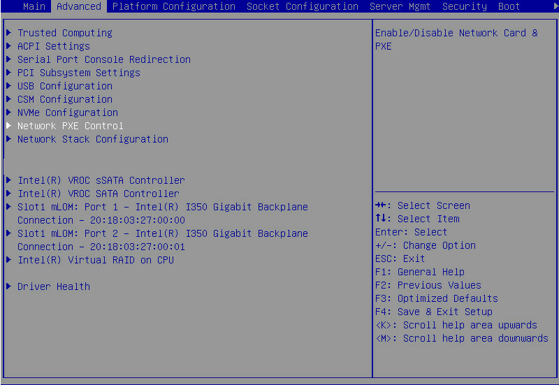
Figure 38 Advanced menu screen (for the B5700, B5800, and B7800)
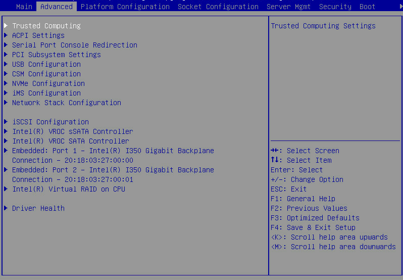
Table 7 Items on the Advanced menu screen
|
Item |
Description |
|
Trusted Computing |
Submenu for configuring trusted computing. |
|
ACPI Settings |
Submenu for configuring advanced configuration and power interface (ACPI) settings. |
|
Submenu for configuring serial console port redirection. |
|
|
PCI Subsystem Settings |
Submenu for configuring the PCI subsystem. |
|
USB Configuration |
Submenu for configuring USB. |
|
CSM Configuration |
Submenu for configuring the compatibility support module (CSM). |
|
NVMe Configuration |
Submenu for configuring NVMe. |
|
iMS Configuration |
Submenu for configuring IMS. This submenu is available only for the B5700, B5800, and B7800 servers. |
|
Network PXE Control |
Submenu for configuring network PXE control. This submenu is unavailable for the B5700, B5800, B7800, and R8900 servers. |
|
Network Stack Configuration |
Submenu for configuring network stacks. |
|
iSCSI Configuration |
Submenu for configuring iSCSI. This submenu is available only for the R5300, B5700, B5800, and B7800. |
|
Intel(R) VROC sSATA Controller |
Submenu for configuring Intel(R) VROC sSATA controller. This submenu is available only when the RAID mode is used in the PCH settings. |
|
Intel(R) VROC SATA Controller |
Submenu for configuring Intel(R) VROC SATA controller. This submenu is available only when the RAID mode is used in the PCH settings. |
|
Slot x:Port x |
Submenu for configuring an Ethernet interface, storage controller, or NVMe drive that has an Option ROM. |
|
Intel(R) Virtual RAID on CPU |
Submenu for configuring Intel(R) Virtual RAID on CPU (Intel VROC). This submenu is available only when VMD is enabled. |
|
Intel(R) Optane(TM) DC Persistent Memory Configuration |
Submenu for configuring Optane(TM) DC Persistent Memory. This submenu is available only when Intel DCPMMs are installed in the server. |
|
Driver Health |
Submenu for viewing the health state of drivers or controllers. This submenu is available only in UEFI boot mode. |
Trusted Computing submenu
The server might contain a trusted platform module (TPM) or a trusted cryptography module (TCM).
Trusted Computing submenu screen (no security device installed)
Figure 39 shows a Trusted Computing submenu screen when no security device is installed. The submenu items are described in Table 8.
Figure 39 Trusted Computing submenu screen (no security device installed)
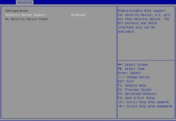
Table 8 Items on the Trusted Computing submenu screen when no security device is installed
|
Item |
Description |
Default |
|
Security Device Support |
Select Enabled or Disabled to enable or disable BIOS support for security devices. |
· R4400: Disabled · Other servers: Enabled |
Trusted Computing submenu screen (TPM module installed)
Figure 40 shows a Trusted Computing submenu screen when a TPM module is installed. The submenu items are described in Table 9.
Figure 40 Trusted Computing submenu screen (TPM module installed)
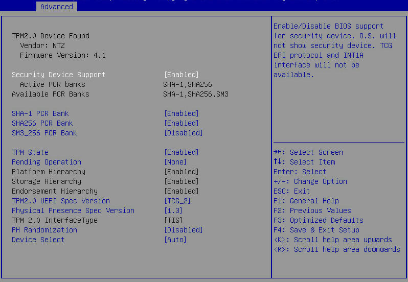
Table 9 Items on the Trusted Computing submenu screen when a TPM module is installed
|
Item |
Description |
Default |
|
Firmware Version |
Displays the firmware version. |
N/A |
|
Vendor |
Displays the name of the vendor. |
N/A |
|
Security Device Support |
Select Enabled or Disabled to enable or disable BIOS support for security devices. |
Enabled |
|
Active PCR banks |
Displays the active platform configuration register (PCR) banks. |
N/A |
|
Available PCR Banks |
Displays the available PCR banks. |
N/A |
|
SHA-1 PCR Bank |
Select Enabled or Disabled to enable or disable the SHA-1 PCR bank. |
Enabled |
|
SHA256 PCR Bank |
Select Enabled or Disabled to enable or disable the SHA256 PCR bank. |
Enabled |
|
SM3_256PCR Bank |
Select Enabled or Disabled to enable or disable the SM3_256 PCR bank. |
Enabled |
|
TPM State |
Select Enabled or Disabled to enable or disable TPM. |
Enabled |
|
Select the TPM operation to be performed during the next boot process. Options are None and TPM Clear. The TPM Clear operation clears the values of measurements in the TPM. |
None |
|
|
Platform Hierarchy |
This item is inaccessible. Select Enabled or Disabled to enable or disable platform hierarchy. |
Enabled |
|
Storage Hierarchy |
This item is inaccessible. Select Enabled or Disabled to enable or disable storage hierarchy. |
Enabled |
|
Endorsement Hierarchy |
This item is inaccessible. Select Enabled or Disabled to enable or disable endorsement hierarchy. |
Enabled |
|
TPM 2.0 UEFI Spec Version |
Select the supported Trusted Computing Group (TCG) specification version. Options: · TCG_1_2—Supports Windows 8 and Windows 10. · TCG_2—Supports TCG 2 protocols, TCG 2 event formats, and Windows 10 or higher. |
TCG_2 |
|
Physical Presence Spec Version |
Select the Physical Presence Interface (PPI) specification version to be reported to the OS. Options: · 1.2. · 1.3. This option is not supported on all HCK tests. |
1.3 |
|
TPM 2.0 InterfaceType |
This item is inaccessible. |
N/A |
|
PH Randomization |
Select Enabled or Disabled to enable or disable platform hierarchy randomization. This feature is used only for tests in the development phase. |
Disabled |
|
Select the supported security device version. Options: · TCM 1.0—Select this option only if a TCM 1.0 module is installed. · TPM 2.0—Select this option only if a TPM 2.0 module is installed. · Auto—Select this option to have the system automatically select TCM 1.0 or TPM 2.0. The default is TPM 2.0. If TPM 2.0 is not present, TCM 1.0 is selected. |
Auto |
Trusted Computing submenu screen (TCM 1.0 module installed)
Figure 41 shows a Trusted Computing submenu screen when a TCM 1.0 module is installed. The submenu items are described in Table 10.
Figure 41 Trusted Computing submenu screen (TCM 1.0 module installed)
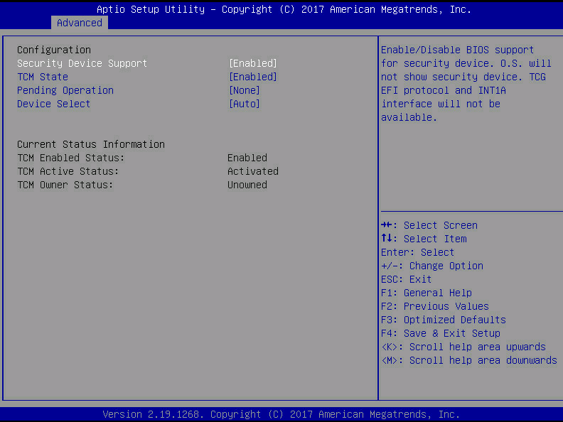
Table 10 Items on the Trusted Computing submenu screen when a TCM 1.0 module is installed
|
Description |
Default |
|
|
Configuration |
||
|
Security Device Support |
Select Enabled or Disabled to enable or disable BIOS support for security devices. |
Enabled |
|
TCM State |
Select Enabled or Disabled to enable or disable TCM. |
Enabled |
|
Pending Operation |
Select the TCM operation to be performed during the next boot process. Options are None and TCM Clear. The TCM Clear operation clears the values of measurements in the TCM. |
None |
|
Device Select |
Select the supported security device version. Options: · TCM 1.0—Select this option only if a TCM 1.0 module is installed. · TPM 2.0—Select this option only if a TPM 2.0 module is installed. · Auto—Select this option to have the system automatically select TCM 1.0 or TPM 2.0. The default is TPM 2.0. If TPM 2.0 is not present, TCM 1.0 is selected. |
Auto |
|
Current Status Information |
||
|
TCM Enabled Status |
Displays whether TCM is enabled or disabled. |
N/A |
|
TCM Active Status |
Displays whether TCM is activated or deactivated. |
N/A |
|
TCM Owner Status |
Displays the TCM ownership state. Options are Owned and Unowned. |
N/A |
ACPI Settings submenu
The ACPI Settings submenu contains the ACPI options for you to configure OS-directed configuration and power management of the server. The submenu items are described in Table 11.
Figure 42 ACPI Settings submenu screen
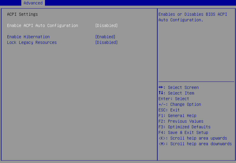
Table 11 Items on the ACPI Settings submenu screen
|
Item |
Description |
Default |
|
Enable ACPI Auto Configuration |
Select Enabled or Disabled to enable or disable ACPI auto configuration. ACPI auto configuration allows the operating system to control and allocate power to the server hardware. |
Disabled |
|
Enable Hibernation |
Select Enabled or Disabled to enable or disable system hibernation. This option takes effect only on some OSs. |
Enabled |
|
Lock Legacy Resources |
Select Enabled or Disabled to enable or disable lock of legacy resources. |
Disabled |
Serial Port Console Redirection submenu
Figure 43 shows the Serial Port Console Redirection submenu screen, on which you can configure console redirection settings as described in Table 12.
Figure 43 Serial Port Console Redirection submenu screen
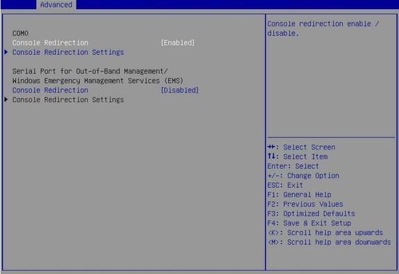
Table 12 Items on the Serial Port Console Redirection submenu screen
|
Item |
Description |
Default |
|
COM0 |
Serial port COM0. |
N/A |
|
Console Redirection |
Select Enabled or Disabled to enable or disable console redirection on COM0. |
Enabled |
|
Open the Console Redirection Settings submenu for COM0, as shown in Figure 44. The Console Redirection Settings submenu is accessible only when Console Redirection is enabled on COM0. |
N/A |
|
|
Serial Port for Out-of-Band Management/Windows Emergency Management Services (EMS) |
Serial port for out-of-band management or Windows Emergency Management Services (EMS). |
N/A |
|
Console Redirection |
Select Enabled or Disabled to enable or disable console redirection on the EMS port. |
Disabled |
|
Console Redirection Settings |
Open the Console Redirection Settings submenu for the EMS port, as shown in Figure 45. The Console Redirection Settings submenu is accessible only when Console Redirection is enabled for the EMS port. |
N/A |
Console Redirection Settings submenu screen (COM0)
Figure 44 shows a Console Redirection Settings submenu screen for serial port COM0. The submenu items are described in Table 13.
Figure 44 Console Redirection Settings submenu screen (COM0)
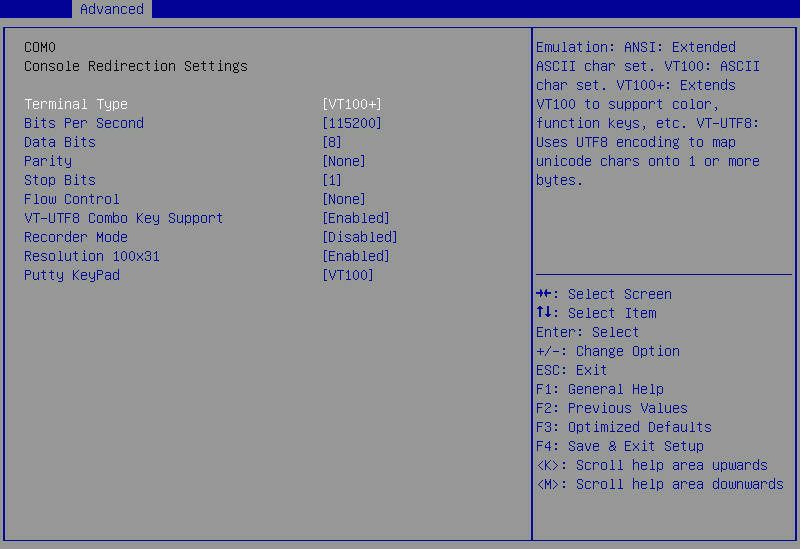
Table 13 Items on the Console Redirection Settings submenu screen (COM0)
|
Item |
Description |
Default |
|
Terminal Type |
Select the type of the terminal used for console redirection. Options: · VT100—Uses a supported VT100 video terminal with the ASCII character set. · VT100+—Uses a supported VT100-plus video terminal and its character set. VT100+ supports colors and function keys. · VT-UTF8—Uses a video terminal with the UTF-8 character set. · ANSI—Uses the ANSI character set, which is an extended ASCII character set. |
VT100+ |
|
Bits Per Second |
Set the baud rate of the serial port in bits per second. Options: · 9600. · 19200. · 38400. · 57600. · 115200. This baud rate setting must match the setting on the remote terminal. As a best practice, set a low speed on a long or noisy serial line. |
115200 |
|
Data Bits |
Set the number of bits used to represent one character of data. Options: · 7. · 8. |
8 |
|
Parity |
Set the parity bit to be sent with the data bits for transmission error detection. Options: · None—No parity bit is sent. · Even—Sets the parity bit so that the number of ones in the data set is an even number. · Odd—Sets the parity bit so that the number of ones in the data set is an odd number. · Mark—Always sets the parity bit to 1. This setting cannot be used for error detection. · Space—Always sets the parity bit to 0. This setting cannot be used for error detection. |
None |
|
Stop Bits |
Set the number of stop bits used to indicate the end of a serial data packet. Options: · 1. · 2. Two stop bits might be required for communications with a slow device. |
1 |
|
Flow Control |
Select a flow control method to prevent data loss from buffer overflow. Options: · None—No flow control is used. · Hardware RTS/CTS—Flow control that uses the ready to send/clear to send (RTS/CTS) signal. When you select this option, make sure it is supported on the serial port. If you enable hardware RTS/CTS on a serial port that does not support hardware flow control (such as a port that uses a USB-to-serial cable), or on a serial port with no cable connected, the following issues might occur: · Failure to load the option ROM of embedded and external PCIe modules. · Screen blackout. · Cursor flickering. |
None |
|
VT-UTF8 Combo Key Support |
Select Enabled or Disabled to enable or disable VT-UTF8 combination key support for ANSI/VT100 terminals. |
Enabled |
|
Recorder Mode |
Select Enabled or Disabled to enable or disable the recorder mode, which is used to capture terminal text data. |
Disabled |
|
Resolution 100×31 |
Select Enabled or Disabled to enable or disable enhanced terminal resolution (100 × 31). |
Enabled |
|
Putty KeyPad |
Select a mode to change the action of the function keys and keypad in PuTTY. Options: · VT100. · LINUX. · XTERMR6. · SCO. · ESCN. · VT400. |
VT100 |
Console Redirection Settings submenu screen (EMS port)
Figure 45 shows a Console Redirection Settings submenu screen for the EMS port. The submenu items are described in Table 14.
Figure 45 Console Redirection Settings submenu screen (EMS port)
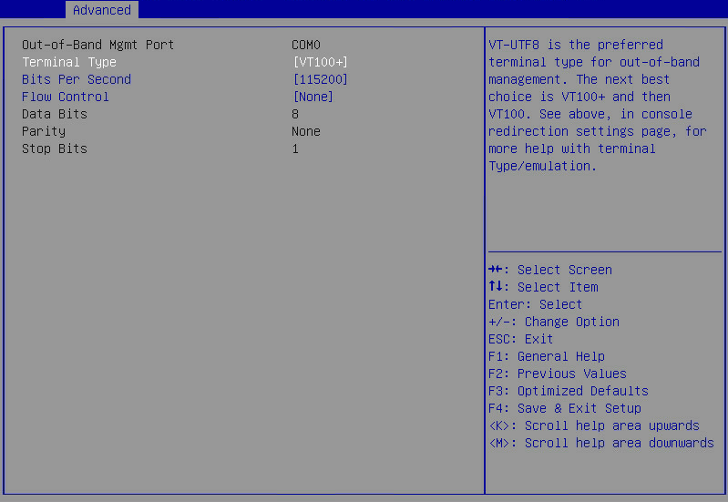
Table 14 Items on the Console Redirection Settings submenu screen (EMS port)
|
Item |
Description |
Default |
|
Out-of-Band Management Port |
Indicate the EMS port. This port allows Microsoft Windows EMS to remotely access the Window OS to collect fault information. |
N/A |
|
Terminal Type |
Select the type of the terminal used for console redirection. Options: · VT100—Uses a supported VT100 video terminal with the ASCII character set. · VT100+—Uses a supported VT100-plus video terminal and its character set. VT100+ supports colors and function keys. · VT-UTF8—Uses a video terminal with the UTF-8 character set. · ANSI—Uses the ANSI character set, which is an extended ASCII character set. |
VT100+ |
|
Bits Per Second |
Set the data transfer rate of the serial port in bits per second. Options: · 9600. · 19200. · 57600. · 115200. This data transfer rate setting must match the setting on the remote terminal. As a best practice, set a low speed on a long or noisy serial line. |
115200 |
|
Flow Control |
Select a flow control method to prevent data loss from buffer overflow. Options: · None—No flow control is used. · Hardware RTS/CTS—Flow control that uses the ready to send/clear to send (RTS/CTS) signal. When you select this option, make sure it is supported on the serial port. · Software Xon/Xoff—Flow control that uses the XON (transmit ON) and XOFF (transmit OFF) control characters. When the data transfer rate exceeds 1200 bits per second, the receiver sends an XOFF to have the sender stop transmission. The sender will resume the transmission only when it receives an XON from the receiver. |
None |
|
Set the number of bits used to represent one character of data. Options: · 7. · 8. |
8 |
|
|
Parity |
Set the parity bit to be sent with the data bits for transmission error detection. Options: · None—No parity bit is sent. · Even—Sets the parity bit so that the number of ones in the data set is an even number. · Odd—Sets the parity bit so that the number of ones in the data set is an odd number. · Mark—Always sets the parity bit to 1. This setting cannot be used for error detection. · Space—Always sets the parity bit to 0. This setting cannot be used for error detection. |
None |
|
Stop Bits |
Set the number of stop bits used to indicate the end of a serial data packet. Options: · 1. · 2. Two stop bits might be required for communications with a slow device. |
1 |
PCI Subsystem Settings submenu
Figure 46 shows the PCI Subsystem Settings submenu screen, on which you can configure PCI subsystem settings as described Table 15.
Figure 46 PCI Subsystem Settings submenu screen
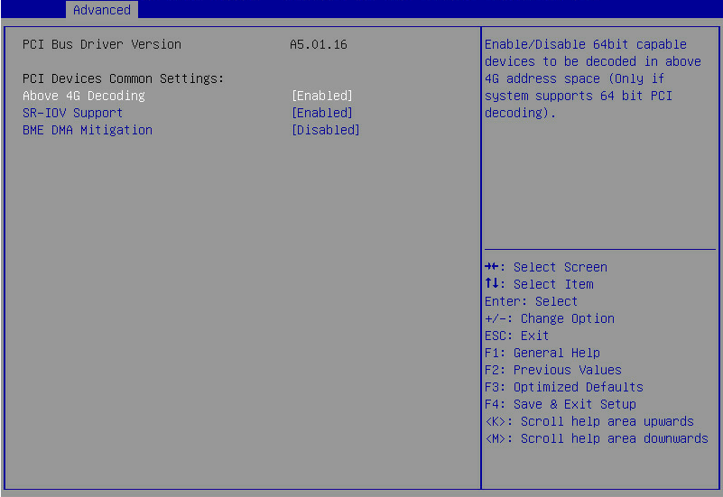
Table 15 Items on the PCI Subsystem Settings submenu screen
|
Item |
Description |
Default |
|
PCI Bus Driver Version |
Displays the PCI bus driver version. |
N/A |
|
PCI Devices Common Settings |
||
|
Above 4G Decoding |
Select Enabled or Disabled to enable or disable decoding of 64-bit PCIe modules in a 4 GB or greater address space. As a best practice, enable this option if the PCIe module has a 4 GB or higher-capacity VRAM. For example, disabling this option can cause an M60 or K80 GPU to get stuck in the EarlyPOST 100% phase, preventing you from accessing the BIOS setup menu or the OS. |
Enabled |
|
SR-IOV Support |
Select Enabled or Disabled to enable or disable the support for PCIe single-root I/O virtualization (SR-IOV). SR-IOV virtualizes one physical PCIe module into multiple virtual PCIe modules, each of which can be bound to a virtual machine, thus allowing multiple accesses to the physical PCIe module. With SR-IOV support enabled, the BIOS allocates I/O resources if a PCIe module supports SR-IOV. With SR-IOV support disabled, the OS allocates I/O resources if a PCIe module supports SR-IOV. |
Enabled |
|
BME DMA Mitigation |
Select Enabled or Disabled to enable or disable DMA attack prevention. With DMA attack prevention disabled, when PCI enumeration detects a PCI to PCI bridge, DMA will not be blocked, and you can still use the nvidia-smi command. |
Disabled |
USB Configuration submenu
Figure 47 shows the USB Configuration submenu screen, on which you can view connected USB devices and configure USB settings as described in Table 16.
Figure 47 USB Configuration submenu screen
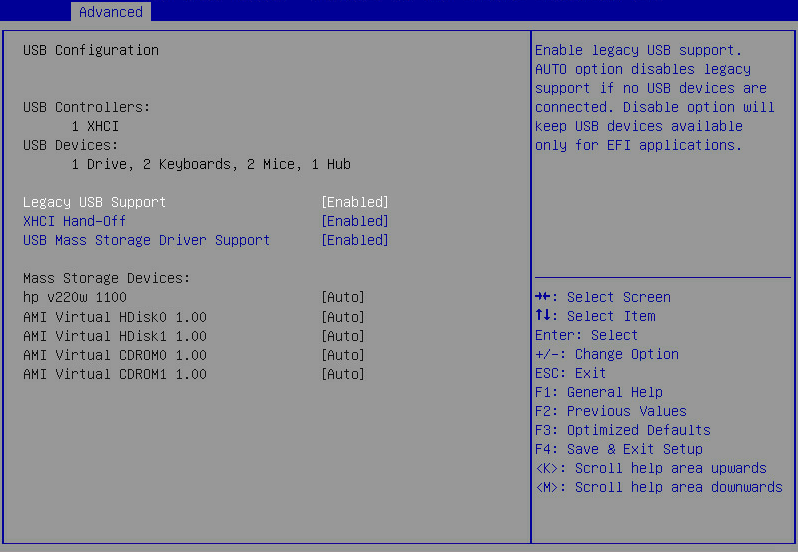
Table 16 Items on the USB Configuration submenu screen
|
Item |
Description |
Default |
|
USB Controllers |
Displays the detected USB controllers. The system supports eXtensible Host Controller (XHCI) controllers that support USB 3.0. |
N/A |
|
USB Devices |
Displays the numbers of connected USB devices, including drives, keyboards, mice, and hubs. The server has one embedded USB hub in addition to the connected USB hubs. |
N/A |
|
Legacy USB Support |
Select whether to enable the support for legacy USB devices. Options: · Enabled—Legacy USB support is always enabled. · Disabled—USB devices are available only for EFI applications. · Auto—The system automatically disables legacy USB support if no USB devices are connected. |
Enabled |
|
XHCI Hand-off |
Select whether to enable the XHCI hand-off feature. This feature specifies the owner of the control over USB 3.0 ports. Options: · Enabled—Hands off the control over USB 3.0 ports to the OS after the OS loads. · Disabled—BIOS controls USB 3.0 ports. |
Enabled |
|
USB Mass Storage Driver Support |
Select Enabled or Disabled to enable or disable the support for USB mass storage drivers. |
Enabled |
|
Mass Storage Devices |
Displays the installed mass storage devices. |
N/A |
|
Dual SD Card RAID LUN |
This option is available only if a dual SD card expander module is installed with a minimum of one SD card. When you manage SD cards, follow these guidelines: · The dual SD card expander module is not hot swappable. However, the SD cards are hot swappable. · For redundancy and storage use efficiency, install two SD cards of the same capacity on the SD card expander module. · If an SD card fails while the server is operating, replace that SD card directly, and then power cycle the server. This replacement procedure ensures that the server can restore the data on the new SD card. Data loss might occur if you replace the failed SD card after powering off the server. |
N/A |
|
ASUS SDR-08B1-U A A301 |
Indicates that an ASUS SDR-08B1-U A A301 USB drive is present. |
N/A |
|
Hp v220w 1100 |
Indicates that an HP v220w 1100 USB drive is present. |
N/A |
|
AMI Virtual HDisk0 1.00 |
Indicates that an AMI Virtual HDisk0 1.00 hard disk is present. |
N/A |
|
AMI Virtual CDROM0 1.00 |
Indicates that an AMI Virtual CDROM0 1.00 drive is present. |
N/A |
CSM Configuration submenu
The configuration support module (CSM) provides UEFI compatibility with OSs that do not support UEFI boot mode.
Figure 48 shows the CSM Configuration submenu screen, on which you can configure CMS settings as described in Table 17.
Figure 48 CSM Configuration submenu screen
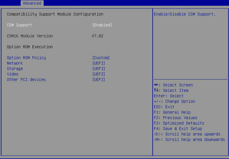
Table 17 Items on the CSM Configuration submenu screen
|
Item |
Description |
Default |
|
CSM Support |
Select Enabled or Disabled to enable or disable support for UEFI-incapable operating systems. In legacy boot mode, the setting is always Enabled and cannot be changed. |
Enabled |
|
CSM16 Module Version |
Displays the version of the CSM 16 module. |
N/A |
|
Option ROM Policy |
Select the option ROM policy. Options: · Auto—Enables the UEFI boot mode for UEFI option ROMs and legacy boot mode for legacy option ROMs. · Custom—Customizes a policy matching with the BIOS boot mode. As a best practice, uses the auto mode to prevent some option ROMs from failing to execute due to incorrect settings. |
Auto |
|
Network |
Select the option ROM load method for Ethernet adapters. This option is available when the option ROM policy is in custom mode. Options: · UEFI—Loads the option ROM for Ethernet adapters in UEFI boot mode. · Legacy—Loads the option ROM for Ethernet adapters in legacy boot mode. |
In UEFI boot mode: UEFI. In legacy boot mode: Legacy. |
|
Storage |
Select the option ROM load method for storage devices. This option is available when the option ROM policy is in custom mode. Options: · UEFI—Loads the option ROM for storage devices in UEFI boot mode. · Legacy—Loads the option ROM for storage devices in legacy boot mode. |
In UEFI boot mode: UEFI. In legacy boot mode: Legacy. |
|
Video |
Select the option ROM load method for video devices. This option is available when the option ROM policy is in custom mode. Options: · UEFI—Loads the option ROM for video cards in UEFI boot mode. · Legacy—Loads the option ROM for video cards in legacy boot mode. |
In UEFI boot mode: UEFI. In legacy boot mode: Legacy. |
|
Other PCI devices |
Select the option ROM load method for other PCI devices such as input devices. This option is available when the option ROM policy is in custom mode. Options: · UEFI—Loads the option ROM for other PCI devices in UEFI boot mode. · Legacy—Loads the option ROM for other PCI devices in legacy boot mode. |
In UEFI boot mode: UEFI. In legacy boot mode: Legacy. |
NVMe Configuration submenu
Figure 49 shows the NVMe Configuration submenu screen, on which all installed NVMe devices without option ROM are displayed. You can select an NVMe device to view its information as shown in Table 18.
Figure 49 NVMe Configuration submenu screen
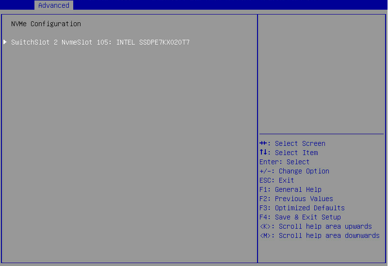
Table 18 Items on the NVMe Configuration submenu screen
|
Item |
Description |
|
SwitchSlot 2 NvmeSlot 105: INTEL SSDPE7KX020T7 |
Open the submenu for the selected NVMe device. The logical slot number of NVMe devices varies by server model. For more information, see Table 20. |
Figure 50 NVMe Device Information submenu screen
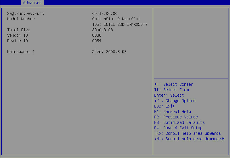
Table 19 Items on the NVMe Device Information submenu screen
|
Item |
Description |
|
Seg:Bus:Dev:Func |
Displays the Seg:Bus:Dev:Func of the NVMe device. |
|
Model Number |
Displays the model number of the NVMe device. |
|
Total Size |
Displays the total size of the NVMe device. |
|
Vendor ID |
Displays the vendor ID of the NVMe device. |
|
Device ID |
Displays the device ID of the NVMe device. |
|
Namespace |
Displays the namespace of the NVMe device. |
Table 20 Description about NVMe logical slot number
|
Server model |
NVMe device type |
Logical slot number |
|
B5700 |
N/A |
Slot 101 or Slot 102. NVMe SSDs 0 and 1 are installed in slot 101 and slot 102, respectively. |
|
B5800 |
N/A |
Slot 106 to Slot 114. The NVMe slot number in the BIOS is consistent with the number of NVMe connector in the server. |
|
B7800 |
N/A |
Slot 101 to Slot 104 The NVMe slot number in the BIOS is consistent with the number of NVMe connector in the server. |
|
E3200 |
N/A |
Slot 1XY. · X—Number of the PCIe riser connector or PCIe slot. The value range is 1 to 5. ¡ 1—PCIe riser connector 1 (for processors 1 and 2). ¡ 2—PCIe riser connector 2 (for processors 1 and 2). ¡ 3—Reserved for future use. ¡ 4—PCIe slot 4 (for processor 1). ¡ 5—PCIe slot 5 (for processor 1). · Y—Number of the NVMe connector. The value range is 1 to 8. For example, Slot 151. |
|
R2700 R2900 R4700 R4900 |
4-port NVMe SSD expander module |
Slot 1XY. · X—Number of the PCIe slot that holds the NVMe SSD. · Y—Number of the NVMe connector. The value range is 0 to 3. For example, Slot 123. |
|
8-port NVMe SSD expander module |
SwitchSlot X NvmeSlot 10Y. · X—Number of the PCIe slot that holds the NVMe SSD. · Y—Number of the NVMe connector. The value range is 0 to 7. For example, SwitchSlot 2 NvmeSlot 105. |
|
|
R4300 |
N/A |
Slot 10X. X represents the number of NVMe connector. The value range is 0 to 5. For example, Slot 100. |
|
R5300 |
N/A |
Slot 20X. X represents the number of NVMe connector. · For the 12LFF server, the value range is 0 to 3. · For the 24LFF server that supports eight NVMe SSDs, the value range is 0 to 7. · For the 24LFF server that supports four NVMe SSDs, the value range is 4 to 7. For example, Slot 203. |
|
R6700 |
N/A |
Slot 2XY. · X—Number of the PCIe riser connector that is used to access the system. ¡ 0—PCIe riser connector 1. ¡ 1—PCIe riser connector 2. · Y—Number of the NVMe connector. For example, Slot 203. |
|
R6900 |
4-port NVMe SSD expander module |
Slot 1XY. · X—Number of the compute module where the SSD resides. ¡ 6—Compute module 1. ¡ 7—Compute module 2. · Y—Number of the NVMe connector. The value range is 0 to 3. For example, Slot 163. |
|
8-port NVMe SSD expander module |
SwitchSlot X NvmeSlot 15Y. · X—Number of the compute module where the SSD resides. ¡ 111—Compute module 1. ¡ 121—Compute module 2. · Y—Number of the NVMe connector. The value range is 0 to 7. For example, SwitchSlot 111 NvmeSlot 153. |
|
|
R8900 |
NVMe SSD |
Slot 2XY. · X—Number of the node used to access the system. The value range is 1 to 4. · Y—Number of NVMe connector. The value range is 0 to 7. For example, Slot 247. |
|
PCIe M.2 SSD |
Slot XY. · X—Number of the PCIe slot. ¡ 2—PCIe slot 2. ¡ 5—PCIe slot 5. · Y—Number of the M.2 transfer module. ¡ 8—M.2 transfer module 1. ¡ 9—M.2 transfer module 2. For example, Slot 28. |
iMS Configuration submenu
Intelligent Memory Surveillance (IMS) provides a set of memory management functions, including memory error detection, memory diagnosis, and memory failure isolation and failure. It reduces memory waste, helps memory troubleshooting, and avoids server failure caused by memory failure.
Figure 51 shows the iMS Configuration submenu screen, on which you can configure IMS. The submenu items are described in Table 21.
Figure 51 iMS Configuration submenu screen
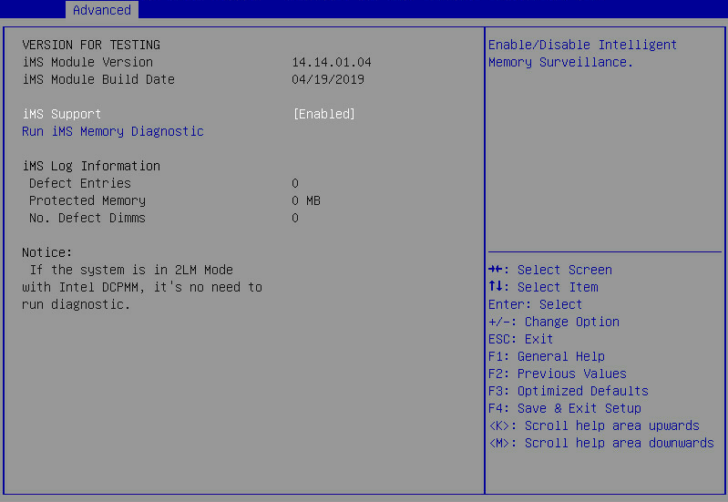
Table 21 Items on the iMS Configuration submenu screen
|
Item |
Description |
Default |
|
VERSION FOR TESTING |
||
|
iMS Module Version |
Displays the version of the IMS module. |
N/A |
|
iMS Module Build Date |
Displays the build date of the IMS module. |
N/A |
|
iMS Support |
Select Enabled or Disabled to enable or disable support for IMS. IMS detects and prevents memory failures in real time after the system starts. |
Enabled |
|
Run iMS Memory Diagnostic |
Run an IMS memory diagnostic test. If the Intel DCPMMs are in 2LM mode, you do not need to run a diagnostic test. |
N/A |
|
iMS Log Information |
||
|
Defect Entries |
Displays the number of log entries about detefected DIMMs, in pages. |
N/A |
|
Protected Memory |
Protected memory capacity, in MB. |
N/A |
|
No. Defect Dimms |
Displays the defected DIMMs. |
N/A |
Figure 52 shows the IMS Memory Diagnostic submenu screen, on which you can run a diagnostic test. Once the test finishes, press any key to reboot the server.
Figure 52 IMS Memory Diagnostic submenu screen
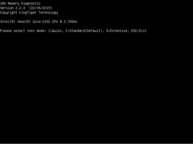
Table 22 Items on the IMS Memory Diagnostic submenu screen
|
Item |
Description |
|
Test mode |
Select a test mode or press ESC to exit the screen. Options: · Quick—Enter 1 to run a quick memory diagnostic test. · Standard—Enter 2 to run a standard memory diagnostic test. · Extensive—Enter 3 to run an extensive memory diagnostic test. |
Network PXE Control submenu
Network PXE control is not supported on the B5700, B5800, B7800, or R8900 server.
Figure 53 shows the Network PXE Control submenu screen, on which all Ethernet adapters are displayed. Each Ethernet adapter is identified by its PCIe slot number and type.
Figure 53 PCIe slot selection screen
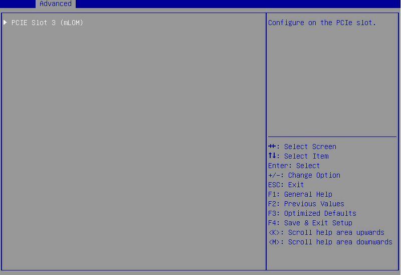
Figure 54 shows the submenu for configuring PXE on an Ethernet adapter. The submenu items are described in Table 23.
Figure 54 Network PXE Control submenu screen
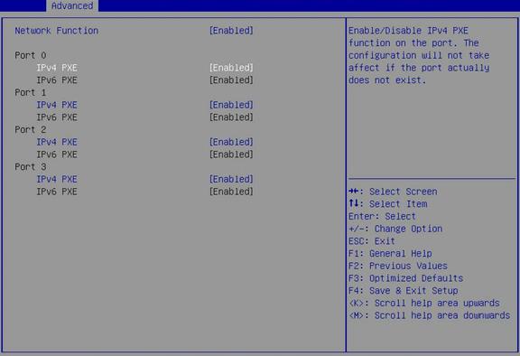
Table 23 Items on the PXE Control submenu screen
|
Item |
Description |
Default |
|
Network Function |
Select Enabled or Disabled to enable or disable the Ethernet adapter. If Disabled is selected, the Ethernet adapter cannot be used in the OS and the PXE function is not available. |
Enabled |
|
Port X |
Displays the port number of the Ethernet adapter, which starts from 0. This option is available when the network function is enabled. |
N/A |
|
IPv4 PXE |
Select Enabled or Disabled to enable or disable the IPv4 PXE control of the Ethernet adapter. This option is available when the network function is enabled. |
Enabled |
|
IPv6 PXE |
Select Enabled or Disabled to enable or disable the IPv6 PXE control of the Ethernet adapter. This option is available when the network function is enabled. |
Enabled |
Network Stack Configuration submenu
Figure 55 shows the Network Stack Configuration submenu screen, on which you can configure PXE boot settings as described in Table 24.
Figure 55 Network Stack Configuration submenu screen
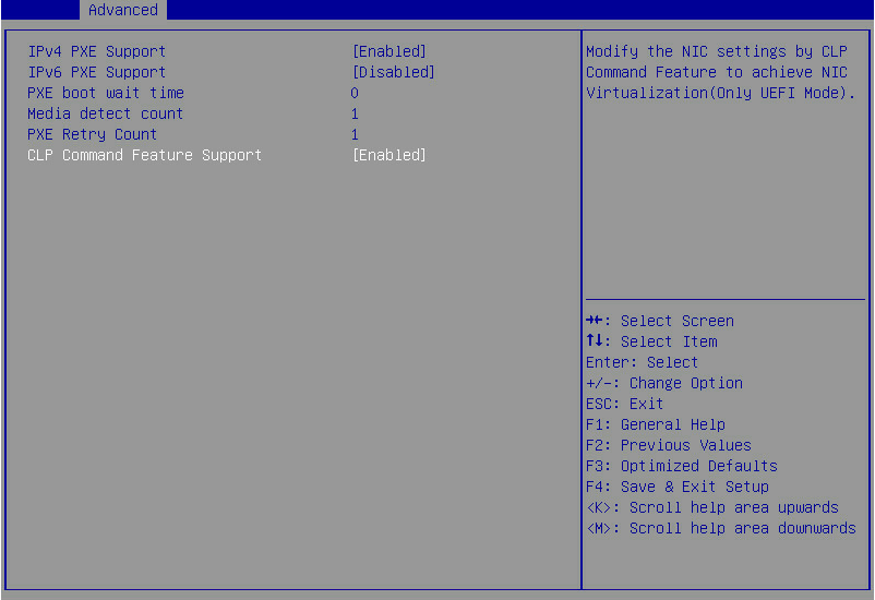
Table 24 Items on the Network Stack Configuration submenu screen
|
Item |
Description |
Default |
|
IPv4 PXE Support |
Select Enabled or Disabled to enable or disable loading the OS over an IPv4 network. If Disabled is selected, the IPv4 PXE boot option will not be created. |
Enabled |
|
IPv6 PXE Support |
Select Enabled or Disabled to enable or disable loading the OS over an IPv6 network. If Disabled is selected, the IPv6 PXE boot option will not be created. |
Disabled |
|
PXE boot wait time |
Set the wait time to press ESC key to abort the PXE boot: · Press + to increase the value by 1. · Press - to decrease the value by 1. Value range: 0 to 5, in seconds. |
0 |
|
Media detect count |
Set the maximum number of media presence detections. Value range: 1 to 50. |
1 |
|
PXE Retry Count |
Set the maximum number of PXE retries. Value range: 0 to 50. A value of 0 indicates that the number of PXE retries is not limited. |
1 |
|
CLP Command Feature Support |
Select Enabled or Disabled to enable or disable the support for CLP commands. You can use CLP commands to modify the Ethernet adapter configuration in an out-of-band way to implement Ethernet adapter virtualization. This option is available only in H3C UniServer B5700, B5800, and B7800 G3 blade servers. |
Enabled |
iSCSI Configuration submenu (for the R5300, B5700, B5800, and B7800 servers)
Figure 56 shows the iSCSI Configuration submenu screen, on which you can configure iSCSI settings as described in Table 25.
Figure 56 iSCSI Configuration submenu screen
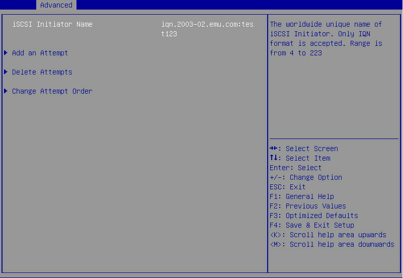
Table 25 Items on the iSCSI Configuration submenu screen
|
Item |
Description |
|
iSCSI Initiator Name |
Set the name of the iSCSI initiator. The name is a string of 4 to 223 characters. The name must be in the IQN format of iqn.YYYY-MM.Domain name:Device name. · YYYY—Year. · MM—Month. · Domain name—Domain name in the reversed order. · Device name. For example, iqn.2003-02.emu.com:test123. |
|
Add an Attempt |
Add an iSCSI attempt. |
|
Delete Attempts |
Delete an iSCSI attempt. |
|
Change Attempt Order |
Change the order of the attempts. |
Add an Attempt submenu screen
Figure 57 shows the Add an Attempt submenu screen, on which all existing attempts are displayed. Each attempt is identified by the MAC address of an iSCSI Ethernet adapter port. The submenu items for each port are the same.
Figure 57 Add an Attempt submenu screen
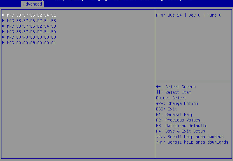
Figure 58 shows the submenu for configuring an attempt. The submenu items are described in Table 26.
Figure 58 Attempt Configuration submenu screen
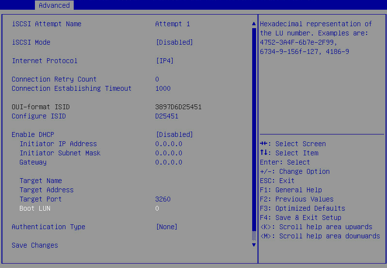
Table 26 Items on the Attempt Configuration submenu screen
|
Item |
Description |
Default |
|
iSCSI Attempt Name |
Set the name of the iSCSI attempt. The name is a case-sensitive string of 1 to 12 characters. |
N/A |
|
iSCSI Mode |
Set the iSCSI mode. Options: · Disabled—Disables iSCSI. · Enabled—Enables iSCSI. · Enabled for MPIO—Enables MPIO iSCSI. |
Disabled |
|
Internet Protocol |
Select the Internet protocol. Options: · IP4—Enables IPv4. · IP6—Enables IPv6. · Autoconfigure—Configures the Internet protocol automatically. IPv4 takes precedence over IPv6. |
IP4 |
|
Connection Retry Count |
Set the maximum number of connection retries. Value range: 0 to 16. A value of 0 indicates no connection retries. |
N/A |
|
Connection Establishing Timeout |
Set the connection timeout time, in milliseconds. |
1000 |
|
OUT-format ISID |
Displays the ID of the iSCSI initiator. |
N/A |
|
Configure ISID |
Configure the ID of the iSCSI initiator. |
The last six digits of the MAC address of the Ethernet adapter port. |
|
Enable DHCP |
Select Enabled or Disabled to enable or disable DHCP. |
Disabled |
|
Initiator IP Address |
Set the IP address of the iSCSI initiator. |
N/A |
|
Initiator Subnet Mask |
Set the subnet mask of the iSCSI initiator. |
N/A |
|
Gateway |
Set the gateway IP address. |
N/A |
|
Target Name |
Set the name of the iSCSI target. |
N/A |
|
Target Address |
Set the name of the iSCSI target. |
N/A |
|
Target Port |
Set the port number of the iSCSI target. |
3260 |
|
Boot LUN |
Set the LUN of the iSCSI target, in hexadecimal notation. |
N/A |
|
Authentication Type |
Select the authentication type. Options: · None. · CHAP. |
None |
|
CHAP Type |
Select the CHAP authentication type. Options: · Mutual—The iSCSI target and iSCSI initiator authenticate each other. · One way—Only the iSCSI target authenticates the iSCSI initiator. |
Mutual |
|
CHAP Name |
Set the name for CHAP authentication. |
N/A |
|
CHAP Secret |
Set the password for CHAP authentication. |
N/A |
|
CHAP Status |
Displays the status of CHAP authentication. |
N/A |
|
Reverse CHAP Name |
Set the name for reverse CHAP authentication. |
N/A |
|
Reverse CHAP Secret |
Set the password for reverse CHAP authentication. |
N/A |
|
Reverse CHAP Status |
Displays the status of reverse CHAP authentication. |
N/A |
|
Save Changes |
Save the changes. |
N/A |
|
Back to Previous Page |
Return to the previous submenu. |
N/A |
Delete Attempts submenu screen
Figure 59 shows the Delete Attempts submenu screen. The items are described in Table 27.
Figure 59 Delete Attempts submenu screen

Table 27 Items on the Delete Attempts submenu screen
|
Item |
Description |
|
Attempt x |
Select the target attempts to delete. |
|
Commit Changes and Exit |
Commit the changes and return to the iSCSI Configuration submenu. |
|
Discard Changes and Exit |
Discard the changes and return to the iSCSI Configuration submenu. |
Change Attempt Order submenu screen
Figure 60 shows the Change Attempt Order submenu screen. The items are described in Table 28.
Figure 60 Change Attempt Order submenu screen
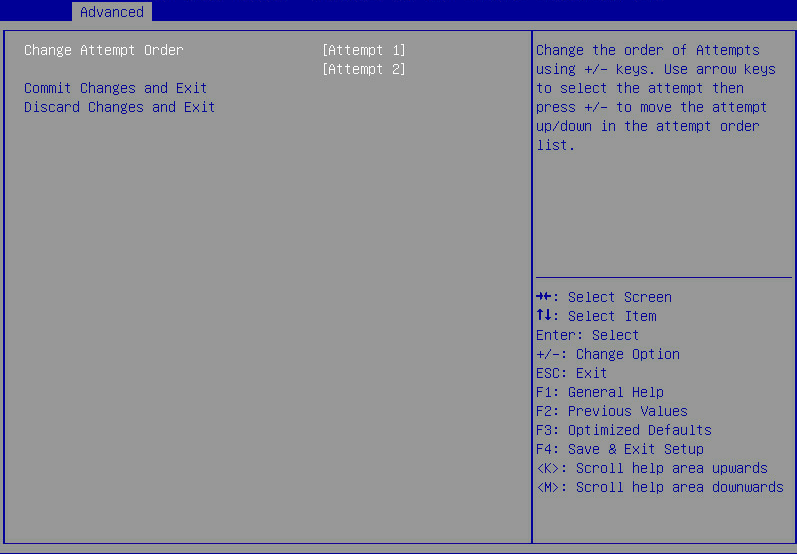
Table 28 Items on the Change Attempt Order submenu screen
|
Item |
Description |
|
Change Attempt Order |
Change the order of existing attempts. Select an attempt and press + or – key to change its order. |
|
Commit Changes and Exit |
Commit the changes and return to the iSCSI Configuration submenu. |
|
Discard Changes and Exit |
Discard the changes and return to the iSCSI Configuration submenu. |
Intel(R) VROC sSATA Controller submenu (for all servers except for the R8900)
The submenus of Intel(R) VROC sSATA controller and Intel(R) VROC SATA controller are available only when the RAID mode is used in the PCH settings.
The submenu screens of Intel(R) VROC sSATA controller and Intel(R) VROC SATA controller are the same. The following uses the submenu screen of Intel(R) VROC sSATA controller for example.
Figure 61 shows the Intel(R) VROC sSATA Controller submenu screen. The submenu items are described in Table 29.
Figure 61 Submenu screen of Intel(R) VROC sSATA controller
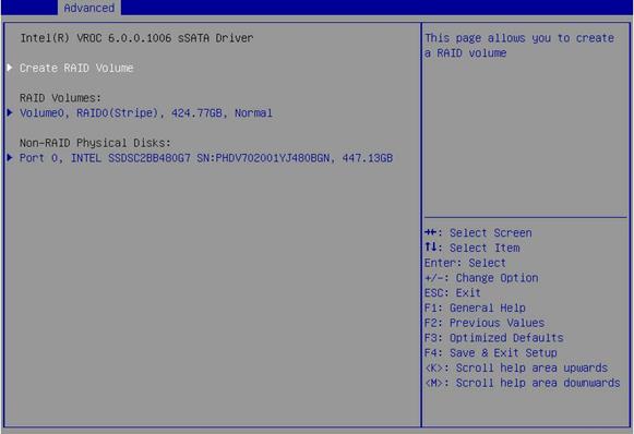
Table 29 Items on the submenu screen of Intel(R) VROC sSATA controller
|
Item |
Description |
|
Create RAID Volume |
Open the submenu for creating a RAID volume. This option is available only when more than two SATA or sSATA drives are connected to the port that is managed by the SATA or sSATA controller. |
|
RAID Volumes |
Displays the list of the created RAID volumes. |
|
Volume0,RAID0(Stripe),424.77GB,Normal |
Displays summary information about managed RAID volumes, including their volume name, RAID level, capacity, and state, for example, Volume0, RAID0 (Stripe), 424.77GB, Normal. |
|
Non-RAID Physical Disks |
Displays the list of the physical drives that have not been used to build RAID volumes. |
|
Port 0,INTEL SSDSC2BB480G7 SN:PHDV702001YJ480BGN,447.14GB |
Displays the information about the non-RAID physical drives, including port number, physical drive name, serial number, and size. |
Create RAID Volume submenu screen
Figure 62 shows the Create RAID Volume submenu screen. The submenu items are described in Table 30.
Figure 62 Create RAID Volume submenu screen
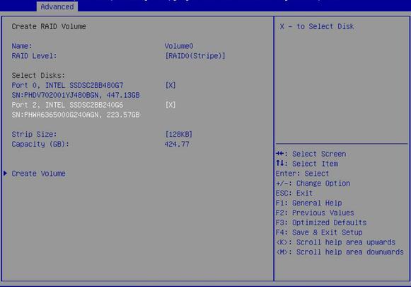
Table 30 Items on the Create RAID Volume submenu screen
|
Item |
Description |
Default |
|
|
Create RAID volume |
|||
|
Name |
Enter the name of the RAID volume. Make sure the name does not contain backslashes (\) or spaces. |
N/A |
|
|
RAID Level |
Select a RAID level. Options: · RAID0(Stripe). · RAID1(Mirror). · RAID5(Parity)—This option is available only when a minimum of three drives are present. · RAID10(RAID0+1)—This option is available only when a minimum of four drives are present. |
RAID0(Stripe) |
|
|
Select Disks |
|||
|
All available drives, for example: Port 0,INTEL SSDSC2BB480G7 SN:PHDV702001YJ480BGN,447.14GB |
Select drives over which you want to create the RAID volume. The selected drive is represented by the symbol X. |
No drives are selected to configure RAID. |
|
|
Stripe Size |
Set the stripe size of the RAID volume, in KB. Options: · 4KB. · 8KB. · 16KB. · 32KB. · 64KB. · 128KB. |
128KB |
|
|
Capacity(GB) |
Displays the total capacity of the RAID volume, in GB. |
N/A |
|
|
Create Volume |
Create a RAID volume. To view information about the configured RAID volumes, select All Intel VMD Controllers. |
N/A |
|
RAID VOLUME INFO submenu screen
Figure 63 shows the RAID VOLUME INFO submenu screen. The submenu items are described in Table 31.
Figure 63 RAID VOLUME INFO submenu screen
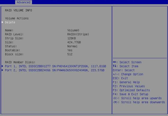
Table 31 Items on the RAID VOLUME INFO submenu screen
|
Item |
Description |
|
Volume Actions |
|
|
Delete |
All data in the member drives of the volume are permanently deleted when the volume is deleted. As a best practice to avoid data loss, back up the data before you delete a volume. To delete the RAID volume, select this item, and then select Yes to confirm the deletion, as shown in Figure 64. |
|
Name |
Displays the name of the RAID volume. |
|
RAID Level |
Displays the RAID level. |
|
Strip Size |
Displays the stripe size of the RAID volume. |
|
Size |
Displays the capacity of the RAID volume. |
|
Status |
Displays the state of the RAID volume. |
|
Bootable |
Displays whether the RAID volume is bootable. |
|
Block Size |
Displays the block size of the RAID volume, in bytes. |
|
RAID Member Disks |
|
|
Member drives of the RAID, for example, Port 1,INTEL SSDSC2BB012T7 SN:PHDV641300NT1P2DGN,1117.81GB |
To manage a member drive or view its detailed information, select that drive and the RAID member drive management submenu opens. |
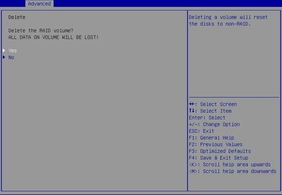
Delete Confirm submenu screen
Figure 64 shows the Delete Confirm submenu screen.
Figure 64 Delete Confirm submenu screen
PHYSICAL DISK INFO submenu screen
Figure 65 shows the PHYSICAL DISK INFO submenu screen. The submenu items are described in Table 32.
Figure 65 PHYSICAL DISK INFO submenu screen

Table 32 Items on the PHYSICAL DISK INFO submenu screen
|
Item |
Description |
|
Disk Actions |
|
|
Reset to non-RAID |
This action deletes all data on the drive. As a best practice to avoid data loss, back up the data before you perform this action. To remove the drive from the RAID array, select this item, and then select Yes to confirm the deletion, as shown in Figure 66. |
|
Turn Locate LED On/Off |
Turn on or turn off the locate LED. |
|
Controller |
Displays the drive controller information, which is sSATA in this example. |
|
Model Number |
Displays the model number of the drive. |
|
Serial Number |
Displays the serial number of the drive. |
|
Size |
Displays the capacity of the drive. |
|
Status |
Displays whether the drive is a RAID member. |
|
Block Size |
Displays the block size of the drive, in bytes. |
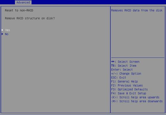
Reset to non-RAID submenu screen
Figure 66 shows the Reset to non-RAID submenu screen.
Figure 66 Reset to non-RAID submenu screen
Non-RAID Physical Disk submenu screen
Figure 67 shows the Non-RAID Physical Disk submenu screen for a non-RAID physical drive. On the screen, you can view information about the drive and set the drive as a spare or journaling drive, as described in Table 33.
Figure 67 Non-RAID Physical Disk submenu screen
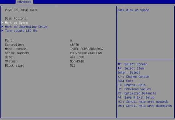
Table 33 Items on the Non-RAID Physical Disk submenu screen
|
Item |
Description |
|
Disk Actions |
|
|
Mark as Spare |
Setting a drive as a spare drive deletes all data on that drive. As a best practice to avoid data loss, back up the data before you perform this action. To specify the drive as a spare drive, select this item, and then select Yes to confirm the action, as shown in Figure 68. A spare drive cannot be used to build a RAID volume. |
|
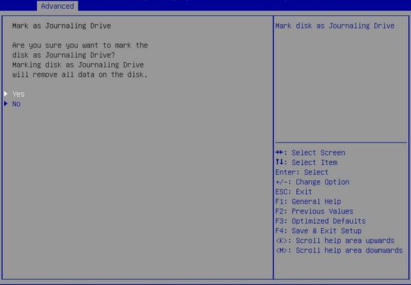
Mark as Journaling Drive |
Setting a drive as a journaling drive deletes all data on that drive. As a best practice to avoid data loss, back up the data before you perform this action. To specify the drive as a journaling drive, select this item, and then select Yes to confirm the action, as shown in Figure 69. A journaling drive cannot be used to build a RAID volume. |
|
Turn Locate LED On/Off |
Turn on or turn off the locate LED. |
|
Port |
Displays the port number of the drive. |
|
Controller |
Displays drive controller information, which is sSATA in this example. |
|
Model Number |
Displays the model number of the drive. |
|
Serial Number |
Displays the serial number of the drive. |
|
Size |
Displays the capacity of the drive. |
|
Status |
Displays whether the drive is a RAID member. |
|
Block Size |
Displays the block size of the drive, in bytes. |
Mark as Spare submenu screen
Figure 68 shows the Mark as Spare submenu screen.
Figure 68 Mark as Spare submenu screen

Mark as Journaling Drive submenu screen
Figure 69 shows the Mark as Journaling Drive submenu screen.
Figure 69 Mark as Journaling Drive submenu screen
Intel(R) Virtual RAID on CPU submenu
Intel® Virtual RAID on CPU (Intel VROC) is a RAID solution specifically designed for NVMe-based SSDs.
If the VMD is disabled, the information about the NVMe SSDs with or without option ROM loaded will be displayed in Slot x:Port x submenu or NVMe Configuration submenu, respectively.
Prerequisites for using Intel VROC
Before using Intel VROC for RAID volume management on a CPU that has NVMe SSDs attached, use the following procedure to enable Intel Volume Management Device (VMD) for that CPU:
1. Install an Intel NVMe VROC module. The system supports the following NVMe VROC modules:
¡ Intel® VROC Standard—Supports RAID levels 0, 1, and 10.
¡ Intel® VROC Premium—Supports RAID levels 0, 1, 5, and 10.
¡ Intel® VROC Intel® SSD Only—Supports RAID levels 0, 1, 5, and 10 and only Intel NVMe SSDs.
2. Enable Intel Volume Management Device (VMD) for that CPU:
a. Select Socket Configuration > IIO Configuration > Intel® VMD technology, and then enable VMD settings. For more information, see IIO Configuration menu.
b. After setting VMD successfully, select Advanced > Intel(R) virtual RAID on CPU, and then press Enter. Table 34 shows the Intel(R) virtual RAID on CPU submenu screen. The submenu items are described in Table 35.
Table 34 Intel(R) virtual RAID on CPU submenu screen
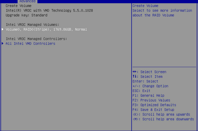
Table 35 Items on the Intel(R) Virtual RAID on CPU submenu screen
|
Item |
Description |
|
Intel VROC Managed Volumes |
Displays summary information about managed RAID volumes, including their volume name, RAID level, capacity, and state, for example, Volume0, RAID0 (Stripe), 1769.86GB, Normal. To view detailed information about a volume or manage its member drives, select that volume. The RAID volume management submenu opens, as shown in Figure 70. For more information about the submenu items, see Table 36. |
|
Intel VROC Managed Controllers |
To view information about Intel VROC managed VMD controllers and use a controller to create and configure a RAID volume, select All Intel VMD Controllers. The all Intel VMD controllers submenu opens, as shown in Figure 74. For more information about the submenu items, see Table 38. |
|
All Intel VMD Controllers |
Submenu for configuring RAID. |
RAID Volume Management submenu screen
Figure 70 shows the RAID Volume Management submenu screen. The submenu items are described in Table 36.
Figure 70 RAID Volume Management submenu screen
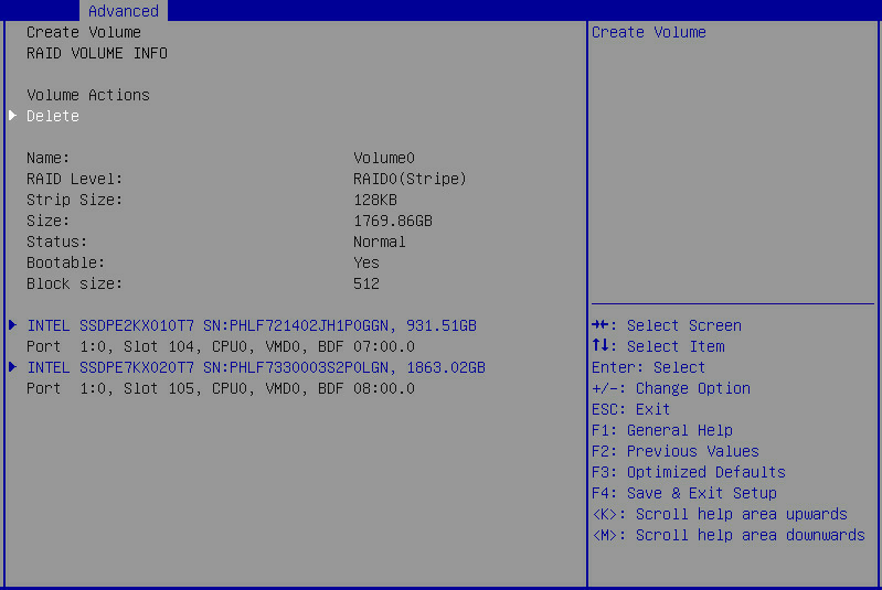
Table 36 Items on the RAID Volume Management submenu screen
|
Item |
Description |
|
Volume Actions |
|
|
Delete |
All data in the member drives of the volume are permanently deleted when the volume is deleted. As a best practice to avoid data loss, back up the data before you delete a volume. To delete the RAID volume, select this item, and then select Yes to confirm the deletion, as shown in Figure 71. |
|
Name |
Displays the name of the RAID volume. |
|
RAID Level |
Displays the RAID level. |
|
Strip Size |
Displays the stripe size of the RAID volume. |
|
Size |
Displays the capacity of the RAID volume. |
|
Status |
Displays the state of the RAID volume. |
|
Bootable |
Displays whether the RAID volume is bootable. |
|
Block Size |
Displays the block size of the RAID volume, in bytes. |
|
RAID Member Disks |
|
|
Member drives of the RAID, for example: · INTEL SSDPE2KX010T7 SN:PHLF721402JH1P0LGN 931.51GB Port 1:0,Slot 104,CPU0,VMD0,BDF 07:00.0 · INTEL SSDPE7KX020T7 SN:PHLF7330003S2P0LGN 1863.02GB Port 1:0,Slot 105,CPU0,VMD0,BDF 08:00.0 |
To manage a member drive or view its detailed information, select that drive. The RAID member drive management submenu opens, as shown in Figure 72. For more information about the submenu items, see Table 37. The port ID depends on the installed NVMe SSD expander module and its installation location. For more information, see Table 20. |
Delete Confirm screen
Figure 71 shows the Delete Confirm screen.
Figure 71 Delete Confirm screen
RAID Member Drive Management submenu screen
Figure 72 shows the RAID Member Drive Management submenu screen. The submenu items are described in Table 37.
Figure 72 RAID Member Drive Management submenu screen
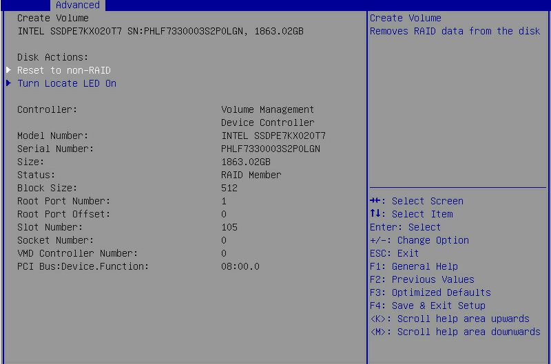
Table 37 Items on the RAID Member Drive Management submenu screen
|
Item |
Description |
|
Disk Actions |
|
|
Reset to non-RAID |
This action deletes all data on the drive. As a best practice to avoid data loss, back up the data before you perform this action. To remove the drive from the RAID array, select this item, and then select Yes to confirm the deletion, as shown in Figure 73. |
|
Turn Locate LED On/Off |
Turn on or turn off the locate LED. |
|
Controller |
Displays the controller information, which is Volume Management Device Controller in this example. |
|
Model Number |
Displays the model number of the drive. |
|
Serial Number |
Displays the serial number of the drive. |
|
Size |
Displays the capacity of the drive. |
|
Status |
Displays whether the drive is a RAID member. |
|
Block Size |
Displays the block size of the drive, in bytes. |
|
Root Port Number |
Displays the root port number of the drive. |
|
Root Port Offset |
Displays the root port offset of the drive. |
|
Slot Number |
Displays the slot number of the drive. |
|
Socket Number |
Displays the slot number of the processor for the drive. |
|
VMD Controller Number |
Displays controller information. |
|
PCI Bus:Device.Function |
Displays the Bus:Dev.Func of the drive. |
Reset to non-RAID screen
Figure 73 shows the Reset to non-RAID screen.
Figure 73 Reset to non-RAID screen

All Intel VMD Controllers submenu screen
Figure 74 shows the All Intel VMD Controllers submenu screen. The submenu items are described in Table 38.
Figure 74 All Intel VMD Controllers submenu screen
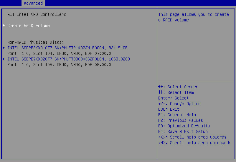
Table 38 Items on the All Intel VMD Controllers submenu screen
|
Item |
Description |
|
Create RAID Volume |
To create a RAID volume, select this item to access the Create RAID Volume screen shown in Figure 75, and then create the RAID volume as described in Table 39. |
|
Non-RAID Physical Disks |
|
|
Drives that are not in a RAID volume, for example: INTEL SSDPE7KX020T7 SN:PHLF7330003S2P0LGN 1863.02GB Port 1:0,Slot 105,CPU0,VMD0,BDF 08:00.0 |
Displays physical drives that are available for creating a RAID volume. To view information about a non-RAID physical drive or set that drive as a spare or journal drive, select that drive to access the non-RAID physical drive submenu shown in Figure 76. For more information about the submenu items, see Table 40. The port ID depends on the installed NVMe SSD expander module and its installation location. For more information, see Table 20. |
Create RAID Volume submenu screen
Figure 75 shows the Create RAID Volume submenu screen. The submenu items are described in Table 39.
Figure 75 Create RAID Volume submenu screen
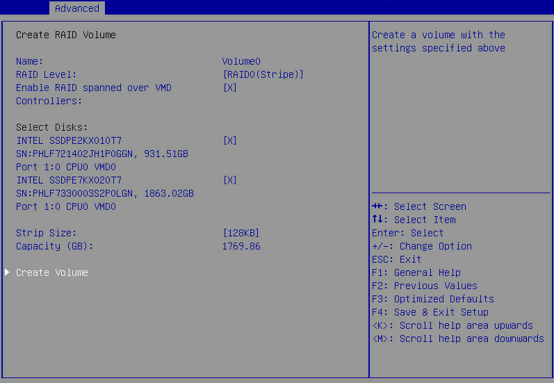
Table 39 Items on the Create RAID Volume submenu screen
|
Item |
Description |
Default |
|
Name |
Enter the name of the RAID volume. Make sure the name does not contain special characters. |
N/A |
|
RAID Level |
Select a RAID level. Options: · RAID0(Stripe). · RAID1(Mirror). · RAID5(Parity). · RAID10(RAID0+1). |
RAID0(Stripe) |
|
Enable RAID spanned over VMD Controllers |
To build a RAID volume over physical drives controlled by different VMD controllers, select this item. |
N/A |
|
Select Disks |
||
|
All available drives, for example: INTEL SSDPE7KX020T7 SN:PHLF7330003S2P0LGN 1863.02GB Port 1:0,Slot 105,CPU0,VMD0,BDF 08:00.0 |
Select drives over which you want to create the RAID volume. If a drive is selected, symbol X is displayed. |
No drives are selected to configure RAID. |
|
Stripe Size |
Set the stripe size of the RAID volume. |
N/A |
|
Capacity (GB) |
Displays the total capacity of the RAID volume. |
N/A |
|
Create Volume |
Select Create Volume and press Enter to create the RAID volume. To verify that the volume is correctly created, examine the RAID Volumes section on the all Intel VMD controllers submenu screen, as shown in Figure 74. |
N/A |
Non-RAID Physical Disk submenu screen
Figure 76 shows the Non-RAID Physical Disk submenu screen for a non-RAID physical drive. On the screen, you can view information about the drive and set the drive as a spare or journaling drive, as described in Table 40.
Figure 76 Non-RAID Physical Disk submenu screen

Table 40 Items on the Non-RAID Physical Disk submenu screen
|
Item |
Description |
|
Disk Actions |
|
|
Mark as Spare |
Setting a drive as a spare drive deletes all data on that drive. As a best practice to avoid data loss, back up the data before you perform this action. To specify the drive as a spare drive, select this item, and then select Yes to confirm the action, as shown in Figure 77. A spare drive cannot be used to build a RAID volume. |
|
Turn Locate LED On/Off |
Turn on or turn off the locate LED. |
|
Controller |
Displays the controller information, which is Volume Management Device Controller in this example. |
|
Model Number |
Displays the model number of the drive. |
|
Serial Number |
Displays the serial number of the drive. |
|
Size |
Displays the capacity of the drive. |
|
Status |
Displays whether the drive is a RAID member. |
|
Block Size |
Displays the block size of the drive. |
|
Root Port Number |
Displays the root port number of the drive. |
|
Root Port Offset |
Displays the root port offset of the drive. |
|
Slot Number |
Displays the slot number of the drive. |
|
Socket Number |
Displays the slot number of the processor for the drive. |
|
VMD Controller Number |
Displays controller information. |
|
PCI Bus:Device.Function |
Displays the Bus:Dev.Func of the drive. |
Mark as Spare screen
Figure 77 shows the Mark as Spare screen.
Figure 77 Mark as Spare screen
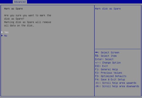
Slot x:Port x submenu
Ethernet interfaces, storage controllers, and NVMe drives that have an Option ROM are displayed on the Advanced screen as Slot x:Port x entries, as shown in Figure 78. For Ethernet interfaces, Slot x represent the slot number of the Ethernet adapter that contains the interface and Port x represents the port index of the interface on the Ethernet adapter.
The Slot x:Port x submenu screen is generated by the option ROM of a PCIe module and the items on the screen vary by vendor. This section uses the Slot 3-mLOM:Port 1 entry for the mLOM Ethernet adapter as an example. Figure 79 shows the Ethernet Adapter Configuration submenu screen of the Slot 3-mLOM:Port 1 entry. The submenu items are described in Table 41.
Figure 78 Slot x:Port x submenu screen
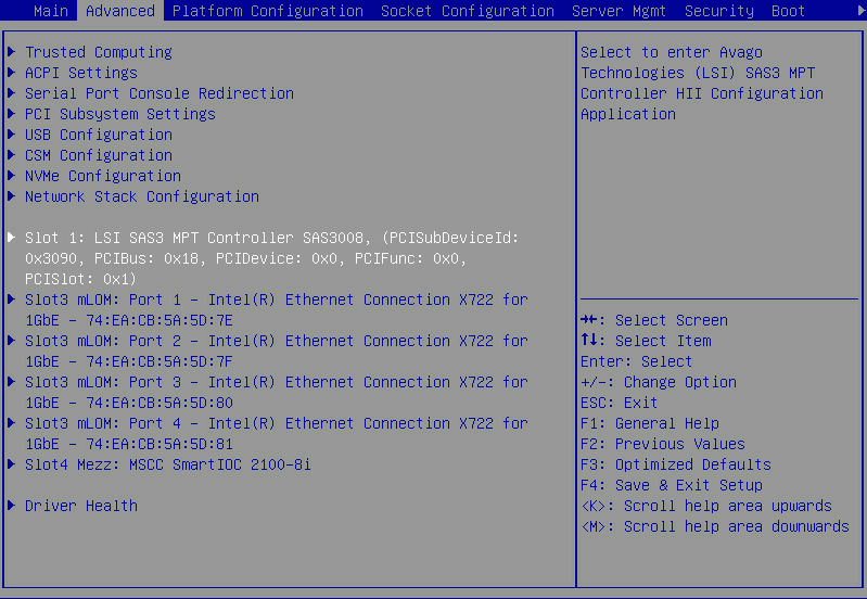
Figure 79 Slot x:Port x entry submenu screen
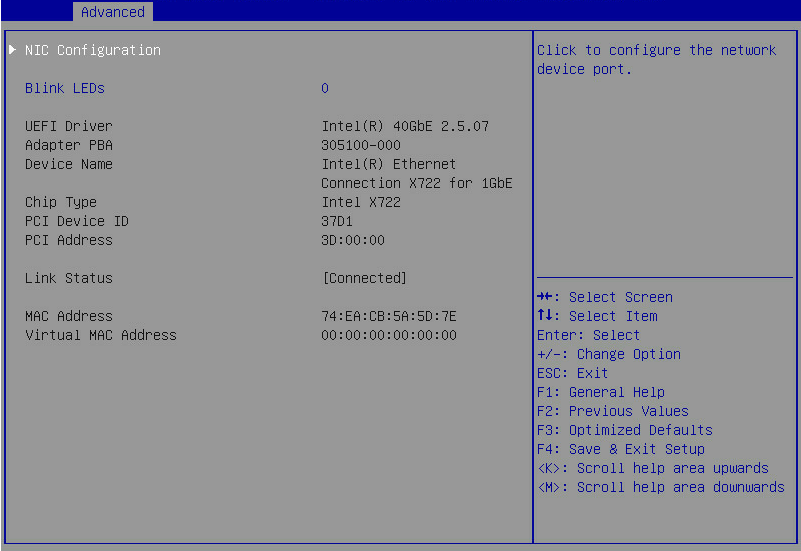
Table 41 Items on the Ethernet Adapter Configuration submenu screen
|
Item |
Description |
Default |
|
NIC Configuration |
Open the Ethernet adapter port configuration submenu, as shown in Figure 80. |
N/A |
|
Blink LEDs |
Set the number of seconds for which the port connection status LED keeps blinking. Value range: 0 to 15. |
0 |
|
UEFI Driver |
Displays the UEFI driver name. |
N/A |
|
Adapter PBA |
Displays the network adapter PBA number. |
N/A |
|
Device Name |
Displays the name of the embedded Ethernet adapter. |
N/A |
|
Chip Type |
Displays the chip type of the Ethernet adapter. |
N/A |
|
PCI Device ID |
Displays the ID of the PCI device. |
N/A |
|
PCI Address |
Displays the address of the PCI device. |
N/A |
|
Link Status |
Displays the link status. Options: · Disconnected. · Connected. |
N/A |
|
MAC Address |
Displays the MAC address of the embedded Ethernet adapter. |
N/A |
|
Virtual MAC Address |
Displays the virtual MAC address of the embedded Ethernet adapter. |
N/A |
Figure 80 shows the Ethernet Adapter Port Configuration screen, on which you can configure the link speed and Wake On LAN for the Ethernet interface as described in Table 42.
Figure 80 Ethernet Adapter Port Configuration screen (Slot 3-mLom : Port 1)
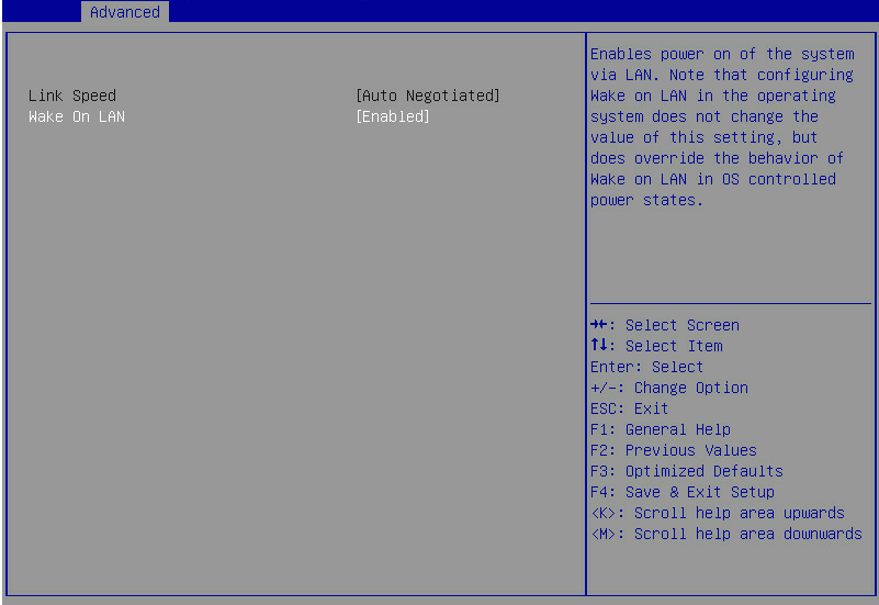
Table 42 Items on the Ethernet Adapter Port Configuration submenu screen
|
Item |
Description |
Default |
|
Link Speed |
Set the link speed. The setting is fixed at Auto Negotiated, which is not user configurable. |
N/A |
|
Wake On LAN |
Select Enabled or Disabled to enable or disable waking up the system from a low power mode remotely. If this option is enabled, the server is woke up when it receives an out-of-band magic packet. |
Enabled |
Intel(R) Optane(TM) DC Persistent Memory Configuration submenu
Figure 81 shows the Intel(R) Optane(TM) DC Persistent Memory Configuration submenu screen, on which you can view and configure Intel DCPMMs installed in the server. For more information about the submenu items, see Table 43. If no Intel DCPMMs are installed, this submenu is unavailable.
Figure 81 Intel(R) Optane(TM) DC Persistent Memory Configuration submenu screen
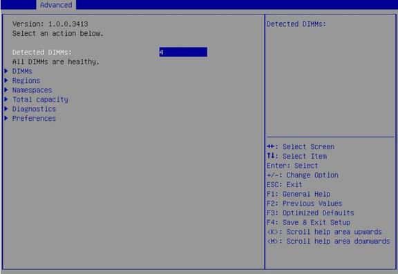
Table 43 Items on the Intel(R) Optane(TM) DC Persistent Memory Configuration submenu screen
|
Item |
Description |
|
Detected DIMMs |
Displays the number of Intel DCPMMs. |
|
DIMMs |
Submenu for configuring Intel DCPMMs. |
|
Regions |
Submenu for configuring regions. |
|
Namespaces |
Submenu for configuring namespaces. |
|
Total capacity |
Submenu for displaying the total capacity. |
|
Diagnostics |
Submenu for configuring diagnostic tests. |
|
Preferences |
Submenu for configuring preferences. |
DIMMs submenu screen
Figure 82 shows the DIMMs submenu screen on which you can view and configure the installed Intel DCPMMs. The submenu items are described in Table 44.
Figure 82 DIMMs submenu screen
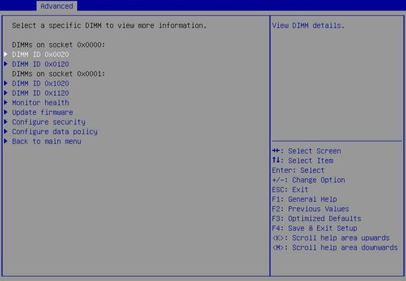
Table 44 Items on the DIMMs submenu screen
|
Item |
Description |
|
DIMM ID |
Submenu for configuring an Intel DCPMM identified by its DCPMM ID. |
|
Monitor health |
Submenu for configuring sensors. |
|
Update firmware |
Submenu for updating the firmware. |
|
Configure security |
Submenu for configuring security settings. |
|
Configure data policy |
Submenu for configuring the data policy. |
|
Back to main menu |
Return to the Intel(R) Optane(TM) DC Persistent Memory Configuration submenu. |
Figure 83, Figure 84, Figure 85, Figure 86, and Figure 87 show the DIMM Configuration submenu screen, on which you can view and configure an Intel DCPMM. The submenu items are described in Table 45.
Figure 83 DIMM Configuration submenu screen (1)
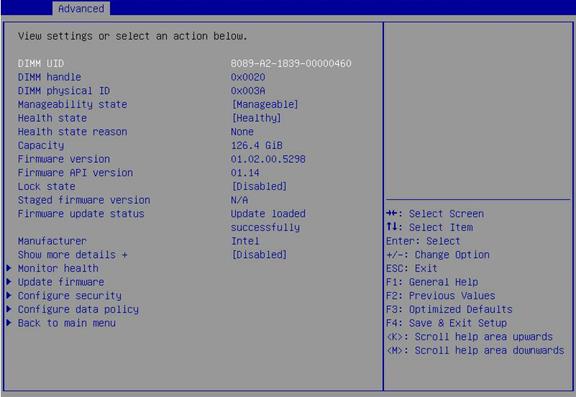
Figure 84 DIMM Configuration submenu screen (2)
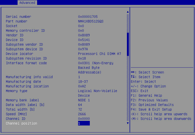
Figure 85 DIMM Configuration submenu screen (3)
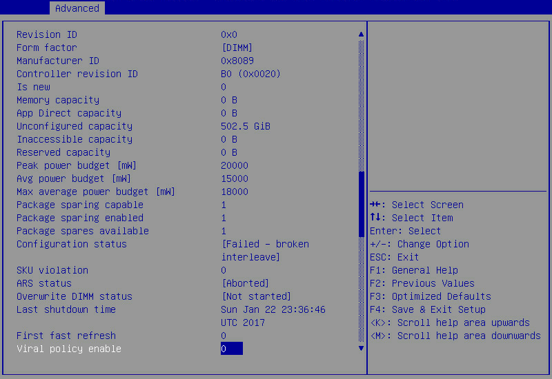
Figure 86 DIMM Configuration submenu screen (4)
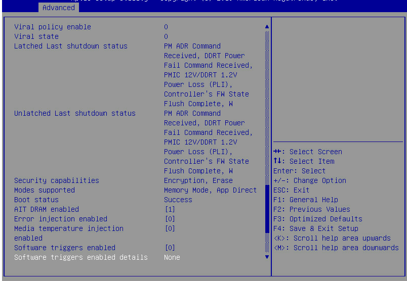
Figure 87 DIMM Configuration submenu screen (5)
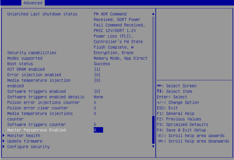
Table 45 Items on the DIMM Configuration submenu screen
|
Item |
Description |
Default |
|
DIMM UID |
Displays the unique ID of the Intel DCPMM. Typically, the ID is in the VVVV-ML-MDMD-SNSNSNSN format. If the manufacturing information is unavailable, it is in the VVVV-SNSNSNSN format. · VVVV—Vendor ID. · ML—Manufacturing location. · MDMD—Manufacturing date. · SNSNSNSN—Serial number. |
N/A |
|
DIMM handle |
Displays the Intel DCPMM handle, which is defined by ACPI. |
N/A |
|
DIMM physical ID |
Displays the Intel DCPMM physical ID, in hexadecimal notation. |
N/A |
|
Manageability state |
Displays the Intel DCPMM state. Options: · Manageable—The Intel DCPMM can be managed by the BIOS. · Unmanageable—The Intel DCPMM cannot be managed by the BIOS of the current version. |
N/A |
|
Health state |
Displays the Intel DCPMM health status. Options: · Healthy. · Minor failure. · Critical failure. · Non-recoverable error. · Unknown. · Unmanageable. |
N/A |
|
Health state reason |
Displays the reason why the Intel DCPMM is not healthy. This option displays None if the Intel DCPMM is healthy. |
N/A |
|
Capacity |
Displays the Intel DCPMM capacity. |
N/A |
|
Firmware version |
Displays the firmware version, in the format of PN.RN.SV.bbbb: · PN—2-digit product number. · RN—2-digit revision number. · SV—2-digit security revision number. · bbbb—4-digit build version. |
N/A |
|
Firmware API version |
Displays the firmware API version. |
N/A |
|
Lock state |
Displays the current security state of the persistent memory on the Intel DCPMM. Options: · Unknown—The security state cannot be obtained. For example, the Intel DCPMM cannot be managed by the BIOS. · Disabled—Security is disabled. · Unlocked—Security is enabled and unlocked. · Locked—Security is enabled and locked. · Frozen—Security can be enabled and unlocked, or disabled. A reboot is required for the state change to take effect. · Exceeded—The password limit has been reached. A power cycle is required to change the state. · Not supported—Security is not supported. |
N/A |
|
Staged firmware version |
Displays the firmware version of each stage. |
N/A |
|
Firmware update status |
Displays the state of the most recent firmware update operation. |
N/A |
|
Manufacturer |
Displays the manufacturer of the Intel DCPMM. |
N/A |
|
Show more details+ |
Select Enabled or Disabled to display or hide detailed Intel DCPMM information. |
N/A |
|
Monitor health |
Submenu for configuring sensors. This option is inaccessible if the manageability state is Unmanageable. |
N/A |
|
Update firmware |
Submenu for updating the firmware. This option is inaccessible if the manageability state is Unmanageable. |
N/A |
|
Configure security |
Submenu for configuring the security settings. This option is inaccessible if the manageability state is Unmanageable. |
N/A |
|
Configure data policy |
Submenu for configuring the data policy. This option is inaccessible if the manageability state is Unmanageable. |
N/A |
|
Back to main menu |
Return to the Intel(R) Optane(TM) DC Persistent Memory Configuration submenu. |
N/A |
|
Intel DCPMM detailed information (The following items are available only when the Show more details + option is set to Enabled.) |
||
|
Serial number |
Displays the serial number, in hexadecimal notation. |
N/A |
|
Part number |
Displays the part number assigned by the vendor. |
N/A |
|
Socket |
Displays the socket number of the processor to which the Intel DCPMM belongs. The socket number is in hexadecimal notation. |
N/A |
|
Memory controller ID |
Displays the memory controller ID, in hexadecimal notation. |
N/A |
|
Vendor ID |
Displays the vendor ID, in hexadecimal notation. |
N/A |
|
Device ID |
Displays the device ID, in hexadecimal notation. |
N/A |
|
Subsystem vendor ID |
Displays the vendor ID of the non-volatile memory subsystem controller, in hexadecimal notation. |
N/A |
|
Subsystem device ID |
Displays the device ID of the non-volatile memory subsystem controller, in hexadecimal notation. |
N/A |
|
Device locator |
Displays the device location, in the format of processor_number-channel_number-DIMM_slot_number. |
N/A |
|
Subsystem revision ID |
Displays the revision ID of the non-volatile memory subsystem controller, in hexadecimal notation. |
N/A |
|
Interface format code |
Displays the code for the DCMPP type, in hexadecimal notation. |
N/A |
|
Manufacturing info valid |
Identifies the validity of the manufacturing location and date. Options: · 0—Invalid. · 1—Valid. |
N/A |
|
Manufacturing date |
Displays the manufacturing date, in hexadecimal notation. This option displays N/A if the value of Manufacturing info valid is 0. |
N/A |
|
Manufacturing location |
Displays the manufacturing location, in hexadecimal notation. This option displays N/A if the value of Manufacturing info valid is 0. |
N/A |
|
Memory type |
Displays the type of the memory, which is Logical Non-Volatile Device in this example. |
N/A |
|
Memory bank label |
Displays the physically labeled bank where the memory device resides. |
N/A |
|
Data width label |
Displays the width used to store user data, in bits. |
N/A |
|
Total width |
Displays the total width used for data and error correction and data redundancy, in bits. |
N/A |
|
Speed |
Displays the maximum frequency of the Intel DCPMM. |
N/A |
|
Channel ID |
Displays the channel ID. |
N/A |
|
Channel position |
Displays the channel position. |
N/A |
|
Revision ID |
Displays the revision ID. |
N/A |
|
Form factor |
Displays the form factor. Options: · DIMM. · SODIMM. · Unknown. |
N/A |
|
Manufacturer ID |
Displays the manufacturer ID. |
N/A |
|
Controller revision ID |
Displays the controller revision ID. |
N/A |
|
Is new |
Displays whether the Intel DCPMM is configured to incorporate with the other Intel DCPMMs in the system. Options: · 0—Yes. · 1—No. |
N/A |
|
Memory capacity |
Displays the Intel DCPMM capacity configured for use in memory mode. |
N/A |
|
App Direct capacity |
Displays the Intel DCPMM capacity configured for use in App Direct mode. |
N/A |
|
Unconfigured capacity |
Displays the capacity of Intel DCPMMs that cannot be accessed because the capacity is not mapped into the system physical address space. |
N/A |
|
Inaccessible capacity |
Displays the capacity of Intel DCPMMs that cannot be accessed because of a licensing issue. |
N/A |
|
Reserved capacity |
Displays the Intel DCPMM capacity reserved for proper alignment of the memory mode capacity. |
N/A |
|
Peak power budget [mW] |
Displays the instantaneous power budget when the Intel DCPMM firmware power management policy is enabled. Value range: 10000 to 20000, in mW. |
10000 |
|
Avg power budget [mW] |
Displays the average power budget when the Intel DCPMM firmware power management policy is enabled. Value range: 10000 to 18000, in mW. |
10000 |
|
Max average power budget [mW] |
Displays the maximum average power budget. Value range: 10000 to 18000, in mW. |
N/A |
|
Package sparing capable |
Select 0 or 1 to disable or enable support for the package sparing policy. |
N/A |
|
Package sparing enabled |
Select 0 or 1 to disable or enable package sparing policy. |
N/A |
|
Package spares available |
Displays the number of spare devices available for package sparing. |
N/A |
|
Configuration status |
Displays the configuration state of the Intel DCPMM. Options: · Valid—The configuration is valid. · Not configured—The Intel DCPMM has not been configured. · Failed - bad configuration—The configuration is corrupted. · Failed- broken interleave—The Intel DCPMM is part of an interleave set that is not complete. · Failed – reverted—The configuration failed and was restored to the most recent known correct configuration. · Failed – unsupported—The configuration is incompatible with the installed BIOS. |
N/A |
|
SKU violation |
Displays whether the Intel DCPMM configuration is supported in case of a licensing issue. Options: · 0—Not supported. · 1—Supported. |
N/A |
|
ARS status |
Displays the Address Range Scrub (ARS) operation state. Options: · Unknown—The ARS operation state cannot be determined. · Not started—No ARS operation was run at the most recent boot. · In progress—An ARS operation is in progress. · Completed—The ARS operation finished at the most recent boot. · Aborted—The ARS operation was aborted at the most recent boot. |
N/A |
|
Overwrite DIMM status |
Displays the Intel DCPMM overwrite operation state. Options: · Unknown—The overwrite operation state cannot be determined. · Not started—No overwrite operation was run at the most recent boot. · In progress—An overwrite operation is in progress. · Completed—The overwrite operation finished and a reboot is required to use the Intel DCPMM. |
N/A |
|
Last shutdown time |
Displays the time for the most recent system shutdown. |
N/A |
|
First fast refresh |
Select 0 or 1 to disable or enable the acceleration of the first refresh cycle for the Intel DCPMM. Before starting the benchmark test, you must wait for a pre-determined time (5 to 6 minutes). |
N/A |
|
Viral policy enable |
Select 0 or 1 to disable or enable the viral policy. If the host operating system software detects an uncorrectable error situation and indicates the viral state, the persistent memory enters into the read-only mode to prevent the spread of the damage. |
N/A |
|
Viral state |
Displays whether the memory is currently viral. Options: · 0—Not viral. · 1—Viral. |
N/A |
|
Latched Last shutdown status |
Displays the most recent latched shutdown state of the Intel DCPMM. Options: · Unknown—The most recent shutdown state cannot be determined. · FW Flush Complete—Firmware flush finished. · PM ADR Command—Power management ADR command received. · PM S3—Power management S3 command received. · PM S5—Power management S5 command received. · DDRT Power Fail Command—DDR power fail command received. · PMIC 12V/DDRT 1.2V Power Loss (PLI)—PMIC power loss. · PM Warm Reset—Power management warm reset received. · Thermal Shutdown—Thermal shutdown triggered. · Controller’s FW Statue Flush Complete—Flush finished. · Viral Interrupt—Viral interrupt received. · Surprise Clock Stop—Surprise clock stop received. · Write Data Flush Complete—Write data flush finished. · PM S4—Power management S4 command received. · PM Idle—Power management idle received. · DDRT Surprise Reset—Surprise reset received. |
N/A |
|
Unlatched last shutdown status |
Displays the most recent unlatched shutdown state of the Intel DCPMM. Options: · Unknown—The most recent shutdown state cannot be determined. · FW Flush Complete—Firmware flush finished. · PM ADR Command—Power management ADR command received. · PM S3—Power management S3 command received. · PM S5—Power management S5 command received. · DDRT Power Fail Command—DDR power fail command received. · PMIC 12V/DDRT 1.2V Power Loss (PLI)—PMIC power lost. · PM Warm Reset—Power management warm reset received. · Thermal Shutdown—Thermal shutdown triggered. · Controller’s FW Statue Flush Complete—Flush finished. · Viral Interrupt—Viral interrupt received. · Surprise Clock Stop—Surprise clock stop received. · Write Data Flush Complete—Write data flush finished. · PM S4—Power management S4 command received. · PM Idle—Power management idle received. · DDRT Surprise Reset—Surprise reset received. |
N/A |
|
Security capabilities |
Displays the security features supported by the Intel DCPMM. Options: · None—The Intel DCPMM does not support any security features. · Encryption—The Intel DCPMM supports persistent memory encryption through password setting. · Erase—The Intel DCPMM is erasable. |
N/A |
|
Modes supported |
Displays a list of modes supported by the Intel DCPMM. Options: · Memory Mode—Intel DCPMMs act as system memory under the control of the OS and all DDR in the platform act as a cache working in conjunction with the Intel DCPMMs. · App Direct—Intel DCPMMs and DDR act as independent memory resources under direct load/store control of the application. |
N/A |
|
Boot status |
Displays the initialization state of the Intel DCPMM reported by the firmware in the boot status register. Options: · Unknown—The boot status register cannot be read. · Success—No errors were reported during initialization. The following states indicate that the media is unavailable and therefore access to user data and operations that require use of the media will fail: · Media not ready—The firmware failed to complete media training. · Media error—The firmware detected an error during media training. · Media disabled—The firmware disabled the media due to a critical issue. The following states indicate that the firmware cannot be reached: · DDRT not ready—The DDRT interface was not initialized properly. · FW Assert—The firmware reported an assert during initialization. · Mailbox not ready—The firmware was unable to initialize a communication interface. |
N/A |
|
AIT DRAM enabled |
Selelct 0 or 1 to disable or enable the Intel DCPMM AIT DRAM. Disabling AIT DRAM will degrade memory performance. |
N/A |
|
Error injection enabled |
Selelct 0 or 1 to disable or enable error injection. |
Disabled |
|
Media temperature injection enabled |
Selelct 0 or 1 to disable or enable media temperature injection. |
Disabled |
|
Software trigger enabled |
Select 0 or 1 to disable or enable software trigger. |
Disabled |
|
Poison error injections counter |
Display the count of poison error injections. This counter is incremented each time the set poison error command is successfully executed. |
N/A |
|
Poison error clear counter |
Display the count of poison error clearances. This counter is incremented each time the clear poison error command is successfully executed. |
N/A |
|
Media temperature injections counter |
Display the count of media temperature injections. This counter is incremented each time the media temperature is injected. |
N/A |
|
Software triggers counter |
Displays the count of software triggers. The counter is incremented each time a software trigger is enabled. |
N/A |
|
Master Passphrase Enabled |
Indicates that the master password is enabled. |
N/A |
Figure 88, Figure 89, and Figure 90 show the Monitor Health submenu screen, on which you can view and configure sensors on all Intel DCPMMs. For more information about the submenu items, see Table 46.
Figure 88 Monitor Health submenu screen (1)
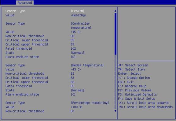
Figure 89 Monitor Health submenu screen (2)
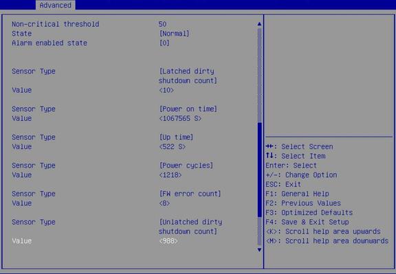
Figure 90 Monitor Health submenu screen (3)
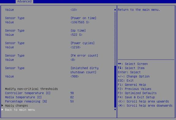
Table 46 Items on the Monitor Health submenu screen
|
Item |
Description |
|
Sensor Type |
Displays the sensor type. Options: · Health. · Controller temperature. · Media temperature. · Percentage remaining. · Latched dirty shutdown count. · Power on time. · Up time. · Power cycles. · FW error count. · Unlatched dirty shutdown count. |
|
Value |
Displays the value of the current sensor. |
|
Non-critical threshold |
Displays the non-critical alarm threshold for the temperature sensor. |
|
Critical lower threshold |
Displays the lower critical alarm threshold for the temperature sensor. |
|
Critical upper threshold |
Displays the upper critical alarm threshold for the temperature sensor. |
|
Fatal threshold |
Displays the fatal alarm threshold for the temperature sensor. |
|
State |
Displays the sensor state. Options: · Unknown. · Normal. · Noncritical. · Critical. · Fatal. This option is displayed only for the controller temperature, media temperature, and percentage remaining sensors. |
|
Alarm enabled state |
Select 0 or 1 to disable or enable alarming. With alarming enabled, the system generates an alarm when the temperature sensor reading exceeds the non-critical alarm threshold. |
|
Modify non-critical thresholds |
|
|
Controller temperature |
Set the threshold of the controller temperature sensor. Value range: 20°C to 105°C (68°F to 221°F). |
|
Media temperature |
Set the threshold of the media temperature sensor. Value range: 20°C to 85°C (68°F to 185°F). |
|
Percentage remaining |
Set the threshold of the percentage remaining sensor. Value range: 1% to 99%. |
|
Apply changes |
Apply the changes. After editing the non-critical threshold of the sensor, apply the changes for the editing to take effect immediately. |
|
Back to main menu |
Return to the Intel(R) Optane(TM) DC Persistent Memory Configuration submenu. |
Figure 91 shows the Update Firmware submenu screen, on which you can view and update the firmware of an Intel DCPMM. For more information about the submenu items, see Table 47.
Figure 91 Update Firmware submenu screen
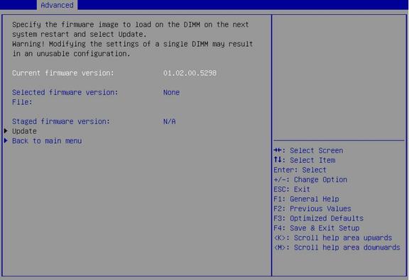
Table 47 Items on the Update Firmware submenu screen
|
Item |
Description |
|
Current firmware version |
Displays the current firmware version. |
|
Selected firmware version |
Displays the selected firmware version. Options: · None—No file path has been entered in the File option. · Incorrect FW—The entered file path is incorrect. · (version)—The version of the firmware in the specified firmware image file is displayed. |
|
File |
Enter the path for saving the firmware file. The path must be a relative path of the root directory, for example, \firmware\newFirmware.bin. |
|
Staged firmware version |
Displays the current staged firmware version. Options: · Mixed—Different versions of firmware are staged on the Intel DCPMMs. · N/A—No firmware is staged on the Intel DCPMMs. |
|
Update |
Update the firmware. After the update, a reboot is required for the new firmware to take effect. |
|
Back to main menu |
Return to the Intel(R) Optane(TM) DC Persistent Memory Configuration submenu. |
Figure 92 shows the Configure Security submenu screen, on which you can configure the security features of an Intel DCPMM. For more information about the submenu items, see Table 48.
Figure 92 Configure Security submenu screen
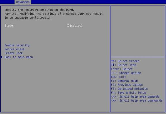
Table 48 Items on the Configure Security submenu screen
|
Item |
Description |
|
State |
Displays the current security state for all Intel DCPMMs in the system. Options: · Disabled—Security is disabled. · Unlocked—Security is enabled and unlocked. · Locked—Security is enabled and locked. · Frozen—Security can be enabled and unlocked, or disabled. A reboot is required for the state change to take effect. · Exceeded—The password limit has been reached. A power cycle is required to change the state. · Not supported—Security is not supported. |
|
Enable security |
Select this option to enable security. After the enabling, a reboot is required for the change to take effect. |
|
Secure erase |
Clear the persistent memory on the Intel DCPMM. This item is available only when the security state of the Intel DCPMM is unlocked or disabled. · If the security state of the Intel DCPMM is unlocked, you must enter the current password. · If the security state of the Intel DCPMM is disabled, you must confirm the operation in the confirm window that opens. |
|
Freeze lock |
Freeze the lock state of the Intel DCPMM till the next reboot. No password is required to change the security state to frozen. |
|
Back to main menu |
Return to the Intel(R) Optane(TM) DC Persistent Memory Configuration submenu. |
Figure 93 shows the Configure Data Policy submenu screen, on which you can configure the data policy of an Intel DCPMM. For more information about the submenu items, see Table 49.
Figure 93 Configure Data Policy submenu screen
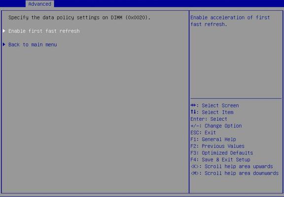
Table 49 Items on the Configure Data Policy submenu screen
|
Item |
Description |
|
First fast refresh state |
Displays the state of the first fast refresh on all Intel DCPMMs. This item is available only if you access the submenu from the Configure data policy item on the DIMM Configuration submenu described in Table 44. Options: · Enabled—First fast refresh is enabled on all Intel DCPMMs. · Disabled—First fast refresh is disabled on all Intel DCPMMs. · Mixed—First fast refresh is enabled on some Intel DCPMMs and disabled on the other Intel DCPMMs. |
|
Enable first fast refresh |
Enables the acceleration of the first fast refresh cycle on the Intel DCPMM. This option is available only when first fast refresh is disabled. |
|
Disable first fast refresh |
Disables the acceleration of the first fast refresh cycle on the Intel DCPMM. This option is available only when first fast refresh is enabled. |
|
Back to main menu |
Return to the Intel(R) Optane(TM) DC Persistent Memory Configuration submenu. |
Regions submenu screen
Memory configuration changes require a reboot to take effect and stays in pending state before the reboot. You can delete the pending configuration (goal configuration) before the reboot for the system to start up with the current configuration.
The system manages persistent memory configurations in the form of regions. Figure 94 shows the Regions submenu screen, on which you can view or configure the current and goal configurations. For more information about the submenu items, see Table 50.
Figure 94 Regions submenu screen
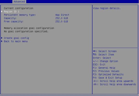
Table 50 Items on the Regions submenu screen
|
Item |
Description |
|
Current configuration |
|
|
Region ID |
Submenu for displaying detailed information about the region. |
|
Persistent memory type |
Displays the current memory type. Options: · App Direct. · App Direct Not Interleaved. |
|
Capacity |
Displays the total capacity of the region, in GB. |
|
Free capacity |
Displays the available capacity of the region, in GB. |
|
Memory allocation goal configuration |
|
|
DIMM ID |
This item is available only when a pending memory allocation goal exists. Submenu for configuring an Intel DCPMM. |
|
MemorySize |
This item is available only when a pending memory allocation goal exists. Displays the memory size for an Intel DCPMM. |
|
AppDirect1Size |
This item is available only when a pending memory allocation goal exists. Displays the size of App Direct 1. |
|
AppDirect2Size |
This item is available only when a pending memory allocation goal exists. Displays the size of App Direct 2. |
|
Create goal config |
Creates goal configuration. |
|
Delete goal config |
Deletes goal configuration. This item is available only if pending goal configurations exist. |
|
Back to main menu |
Return to the Intel(R) Optane(TM) DC Persistent Memory Configuration submenu. |
Figure 95 shows the Region Detailed Information submenu screen, on which you can view the detailed information about the persistent memory configuration. For more information about the submenu items, see Table 51.
Figure 95 Region Detailed Information submenu screen
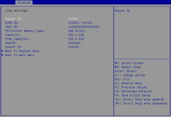
Table 51 Items on the Region Detailed Information submenu screen
|
Item |
Description |
Default |
|
Region ID |
Displays the region ID, in hexadecimal notation. |
N/A |
|
DIMM ID |
Displays the IDs of the Intel DCPMMs contained in the region. |
N/A |
|
ISet ID |
Displays the ISet ID. |
N/A |
|
Persistent memory type |
Displays the type of persistent memory capacity. Options: · App Direct—The App Direct capacity is interleaved across two or more Intel DCPMMs. · App Direct Not Interleaved—The App Direct capacity is wholly contained on a single Intel DCPMM. |
App Direct |
|
Capacity |
Displays the total usable capacity, the sum of allocated capacity and unallocated capacity. |
N/A |
|
Free capacity |
Displays the remaining usable capacity. |
N/A |
|
Health |
Displays the health state of the Intel DCPMM capacity. Options: · Health—All underlying Intel DCPMM persistent memory is available. · Pending—A new memory allocation goal has been created but not been applied. · Error—The interleave set has failed. · Locked—One or more of the underlying Intel DCPMMs are locked. · Unknown—The region health cannot be determined. |
N/A |
|
Socket ID |
Displays the socket ID to which the region belongs. |
N/A |
|
Back to Regions menu |
Return to the Regions submenu. |
N/A |
|
Back to main menu |
Return to the Intel(R) Optane(TM) DC Persistent Memory Configuration submenu. |
N/A |
Figure 96 shows the View Goal Config submenu screen, on which you can view the detailed information about a configuration goal. For more information about the submenu items, see Table 52.
Figure 96 View Goal Config submenu screen
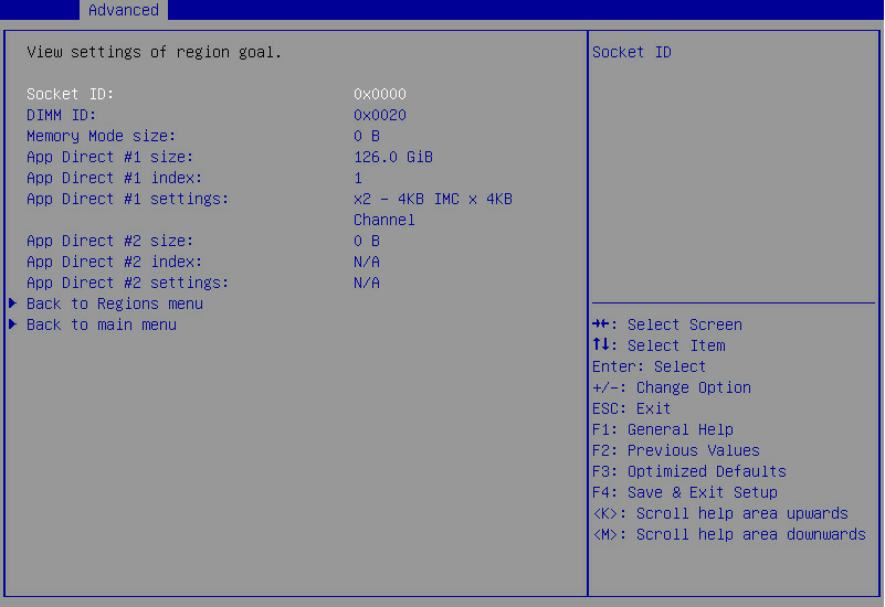
Table 52 Items on the View Goal Config submenu screen
|
Item |
Description |
|
Socket ID |
Displays the ID of the socket to which the Intel DCPMM belongs. |
|
DIMM ID |
Displays the Intel DCPMM ID. |
|
Memory Mode size |
Displays the capacity of the Intel DCPMM that will be configured in memory mode. |
|
App Direct #1 size |
Displays the capacity of the Intel DCPMM that will be configured as the first App Direct interleave set. |
|
App Direct #1 index |
Displays the unique ID of the first App Direct interleave set. This item displays N/A when the size of the App Direct #1 is 0. |
|
App Direct #1 setting |
Displays the format of the App Direct 1: x (DIMM ID) – (IMC size) IMC x (Channel size) Channel. This item displays N/A when the size of the App Direct #1 is 0. |
|
App Direct #2 size |
Displays the capacity of the Intel DCPMM that will be configured as the second App Direct interleave set. |
|
App Direct #2 index |
Displays the unique ID of the second App Direct interleave set. This item displays N/A when the size of the App Direct #2 is 0. |
|
App Direct #2 setting |
Displays the format of the App Direct 2: x (DIMM ID) – (IMC size) IMC x (Channel size) Channel. This item displays N/A when the size of the App Direct #2 is 0. |
|
Back to Regions menu |
Return to the Regions submenu. |
|
Back to main menu |
Return to the Intel(R) Optane(TM) DC Persistent Memory Configuration submenu. |
Figure 97 shows the Create Goal Config submenu screen, on which you can create a configuration goal. For more information about the submenu items, see Table 53.
Figure 97 Create Goal config submenu screen
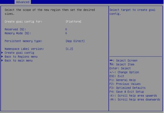
Table 53 Items on the Create Goal Config submenu screen
|
Item |
Description |
Default |
|
Create goal config for |
Select a target to create a goal configuration. Options: · Platform—Creates a memory allocation goal on all the sockets in the platform. · Socket—Creates a memory allocation goal of the Intel DCPMMs on the specified sockets. · Partially-configured sockets—Creates a memory allocation goal on the specified sockets which are partially configured because of the addition of new Intel DCPMMs. A partially-configured socket refers to a socket that has a minimum of one configured Intel DCPMM and a minimum of one unconfigured Intel DCPMM. This option is not displayed if no partially-configured sockets exist. |
Platform |
|
Reserved |
Set the percentage of the reserved capacity, which will not be mapped into the system physical address space. Value range: 0% to 100%. |
N/A |
|
Memory Mode |
Set the percentage of the total capacity to use in memory mode. Value range: 0% to 100%. Because of platform memory alignment requirements, this value will be aligned automatically. |
N/A |
|
Persistent memory type |
Select the type of persistent memory capacity to create. Options: · App Direct—The capacity is interleaved across the Intel DCPMMs. · App Direct Not Interleaved—The capacity is not hardware interleaved. This item is inaccessible when the Memory Mode item is set to 100%. |
N/A |
|
Namespace Label version |
Displays the version of the namespace label. Options: · 1.2. · 1.1. |
N/A |
|
Create goal config |
Create a configuration goal on the selected target. |
N/A |
|
Back to Regions menu |
Return to the Regions submenu. |
N/A |
|
Back to main menu |
Return to the Intel(R) Optane(TM) DC Persistent Memory Configuration submenu. |
N/A |
Figure 98 shows the Delete Goal Config submenu screen, on which you can delete the goal configuration. For more information about the submenu items, see Table 54.
Figure 98 Delete Goal Config submenu screen
Table 54 Items on the Delete Goal Config submenu screen
|
Item |
Description |
|
Delete goal config for |
Select the target to delete goal configuration. Options: · Platform. · Socket. |
|
Delete goal config |
Delete goal configuration from the selected target. |
|
Back to Regions menu |
Return to the Regions submenu. |
|
Back to main menu |
Return to the Intel(R) Optane(TM) DC Persistent Memory Configuration submenu. |
Namespaces submenu screen
Figure 99 shows the Namespaces submenu screen, on which you can view and configure namespaces. For more information about the submenu items, see Table 55.
Figure 99 Namespaces submenu screen

Table 55 Items on the Namespaces submenu screen
|
Item |
Description |
|
Namespace ID |
Displays the namespace ID, in hexadecimal notation. This item is available only when a namespace exists in the system. |
|
Name |
Displays the name of namespace. This item is available only when a namespace exists in the system. |
|
Health Status |
Displays the health state. Options: · Healthy. · Warning. · Critical. · Locked. · Unknown. This item is available only when a namespace exists in the system. |
|
Create namespace |
Submenu for creating a namespace |
|
Back to main menu |
Return to the Intel(R) Optane(TM) DC Persistent Memory Configuration submenu. |
Figure 100 shows the Create Namespace submenu screen, on which you can create a namespace. For more information about the submenu items, see Table 56.
Figure 100 Create Namespace submenu screen
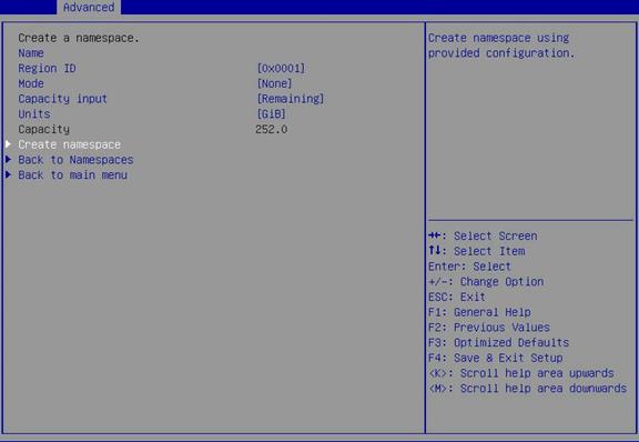
Table 56 Items on the Create Namespace submenu screen
|
Item |
Description |
Default |
|
Name |
Enter the name of the namespace to be created. The name can contain a maximum of 63 characters. |
N/A |
|
Region ID |
Set the region ID of the namespace. |
N/A |
|
Mode |
Set the namespace mode. Options: · None—Allows only raw access. · Sector—Guarantees powerfail write atomicity by using a block translation table (BTT). |
None |
|
Capacity input |
Select to use the maximum available capacity or enter the capacity manually. Options: · Remaining—Select this option to use the maximum available capacity of the specified persistent memory type on the specified region for the new namespace. · Manual—Select this option to enter the capacity for the new namespace manually. |
Remaining |
|
Units |
Set the capacity unit. Options: · GiB. · GB. · B. · MB. · MiB. · TB. · TiB. |
GiB |
|
Capacity |
Displays the namespace capacity. This item is inaccessible if the Capacity input item is set to Remaining. |
N/A |
|
Create namespace |
Submenu for creating a namespace |
N/A |
|
Back to Namespaces |
Return to the Namespaces submenu. |
N/A |
|
Back to main menu |
Return to the Intel(R) Optane(TM) DC Persistent Memory Configuration submenu. |
N/A |
Figure 101 shows the Modify Namespace submenu screen, on which you can modify or delete a namespace. For the new configuration to take effect, you must select Save and then press Enter. For more information about the submenu items, see Table 57.
Figure 101 Modify Namespace submenu screen
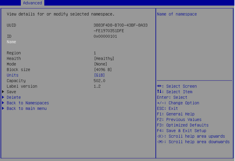
Table 57 Items on the Modify Namespace submenu screen
|
Item |
Description |
|
UUID |
Displays the universal unique identifier (UUID) of the namespace. |
|
ID |
Displays the ID of the namespace, in hexadecimal notation. |
|
Name |
Displays the name of the namespace. |
|
Region |
Displays the region ID of the namespace, in decimal notation. |
|
Health |
Displays the health state of the underlying Intel DCPMMs. Options: · Healthy. · Warning. · Critical. · Locked. · Unknown. · Unsupported—The namespace type is not supported. |
|
Mode |
Displays the namespace mode. Options: · Sector—Guarantees powerfail write atomicity by using a block translation table (BTT). · Fsdax—Supports filesystem-dax. · None—Allows only raw access. |
|
Block size |
Displays the logical block size. |
|
Units |
Displays the capacity unit. Options: · GiB. · GB. · B. · MB. · MiB. · TB. · TiB. |
|
Capacity |
Displays the usable namespace capacity. |
|
Label Version |
Displays the version of the LSA. Options: · 1.1. · 1.2. The label version for all namespaces is the same. |
|
Save |
Save the change. For the configuration changes to take effect, you must save the change. |
|
Delete |
Delete the namespace. |
|
Back to Namespaces |
Return to the Namespaces submenu. |
|
Back to main menu |
Return to the Intel(R) Optane(TM) DC Persistent Memory Configuration submenu. |
Total Capacity submenu
Figure 102 shows the Total Capacity submenu screen, on which you can view the total Intel DCPMM memory resource allocation across the server. For more information about the submenu items, see Table 58.
Figure 102 Total Capacity submenu screen
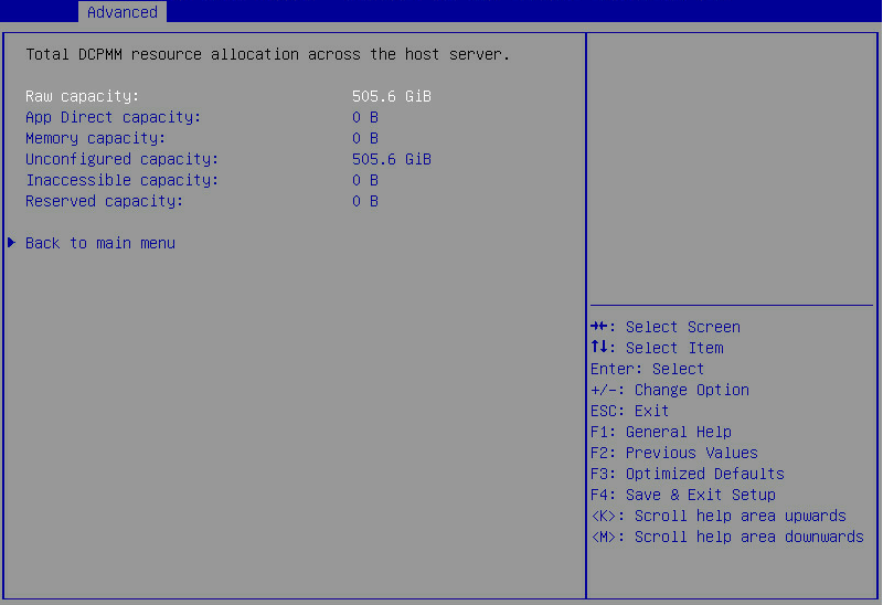
Table 58 Items on the Total Capacity submenu screen
|
Item |
Description |
|
Raw capacity |
Displays the total Intel DCPMM capacity. |
|
App Direct capacity |
Displays the total Intel DCPMM capacity configured to use as APP Direct. |
|
Memory capacity |
Displays the total Intel DCPMM capacity configured to use in memory mode. |
|
Unconfigured capacity |
Displays the capacity of unconfigured Intel DCPMMs that are not mapped into the system physical address space. |
|
Inaccessible capacity |
Displays the capacity of Intel DCPMMs inaccessible because of licensing issues. |
|
Reserved capacity |
Displays the total system Intel DCPMM capacity reserved for proper alignment of the memory mode capacity. |
|
Back to main menu |
Return to the Intel(R) Optane(TM) DC Persistent Memory Configuration submenu. |
Diagnostics submenu
Figure 103 shows the Diagnostics submenu screen, on which you can run a combination of different diagnostic tests. For more information about the submenu items, see Table 59.
Figure 103 Diagnostics submenu screen
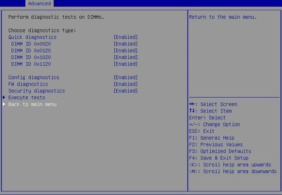
Table 59 Items on the Diagnostics submenu screen
|
Item |
Description |
Default |
|
Quick diagnostics |
Select Enabled or Disabled to enable or disable quick diagnostic test. |
Enabled |
|
DIMM ID |
Select Enabled or Disabled to enable or disable diagnosis on an Intel DCPMM. |
Enabled |
|
Config diagnostics |
Select Enabled or Disabled to enable or disable platform configuration diagnostic test. |
Enabled |
|
FW diagnostics |
Select Enabled or Disabled to enable or disable firmware diagnostic test. |
Enabled |
|
Security diagnostics |
Select Enabled or Disabled to enable or disable security diagnostic test. |
Enabled |
|
Execute tests |
Execute the selected diagnostic tests. This item is inaccessible when one of the following conditions exists: · No test items are enabled. · Quick diagnostic test is enabled but no Intel DCPMMs are selected. |
N/A |
|
Back to main menu |
Return to the Intel(R) Optane(TM) DC Persistent Memory Configuration submenu. |
N/A |
Preferences submenu
Figure 104 shows the Preferences submenu screen, on which you can view or modify user preferences. For more information about the submenu items, see Table 60.
Figure 104 Preferences submenu screen
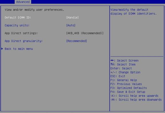
Table 60 Items on the Preferences submenu screen
|
Item |
Description |
Default |
|
Default DIMM ID |
Set the default display of the Intel DCPMM ID. Options: · Handle—Uses the SMBIOS Type 17 handle. · UID—Uses the Intel DCPMM UID set in Table 45. |
Handle |
|
Capacity units |
Set the capacity unit. Options: · Auto. · Auto_10. · B. · MB. · MiB. · GB. · GiB. · TB. · TiB. |
Auto |
|
App Direct settings |
Configure the interleave settings for creating an App Direct capacity. You can use only the BIOS recommended interleave settings, in the format of (IMC size)_(Channel size). This option is inaccessible if an App Direct capacity already exists on the system. |
BIOS recommended interleaving settings |
|
App Direct granularity |
Set the minimum App Direct granularity per Intel DCPMM. Options: · Recommended—Uses the recommended App Direct granularity of 32 GiB. · 1—Uses the granularity of 1 GiB. |
Recommended |
|
Back to main menu |
Return to the Intel(R) Optane(TM) DC Persistent Memory Configuration submenu. |
N/A |
Driver Health submenu
Figure 105 shows the Driver Health submenu screen, on which you can view the health state of a driver or controller. This section uses a controller of a 4-port mLOM Ethernet adapter as an example. The submenu items are described in Table 61.
Figure 105 Driver Health submenu screen
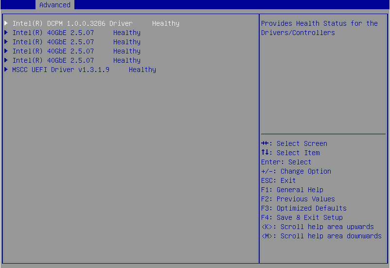
Table 61 Items on the Driver Health submenu screen
|
Item |
Description |
|
Intel(R) DCPM 1.0.0.3286 Driver |
Displays the health state of a driver or a controller. Options: · Healthy—Normal. · Failed—Abnormal. If the state is Failed, press Enter and follow the instructions to repair the driver or controller. The repair method varies by driver or controller. |
Platform Configuration menu
As shown in Figure 106, the Platform Configuration menu contains the submenus described in Table 62.
Figure 106 Platform Configuration menu screen
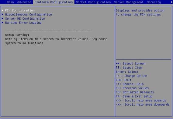
Table 62 Items on the Platform Configuration menu screen
|
Item |
Description |
|
PCH Configuration |
Submenu for configuring the platform controller hub (PCH). |
|
Miscellaneous Configuration |
Submenu for configuring miscellaneous settings, including video display device and debug mode settings. |
|
Server ME Configuration |
Submenu for configuring the server management engine (ME). |
|
Runtime Error Logging |
Submenu for configuring runtime error logging. |
PCH Configuration submenu
Figure 107 shows the PCH Configuration submenu screen, on which you can configure PCH settings as described in Table 63.
Figure 107 PCH Configuration submenu screen
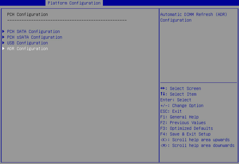
Table 63 Items on the PCH Configuration submenu screen
|
Item |
Description |
|
PCH SATA Configuration |
Submenu for configuring PCH SATA settings, as shown in Figure 108. The submenu menu items are described in Figure 109. NOTE: This submenu is not available for the R8900. |
|
PCH sSATA Configuration |
Submenu for configuring PCH sSATA settings, as shown in Figure 111. The submenu menu items are described in Figure 112. NOTE: This submenu is not available for the R8900. |
|
USB Configuration |
Submenu for configuring USB, as shown in Figure 113 through Figure 126. The submenu menu items are described in Table 69 through Table 82. The submenu items vary by server model. |
|
ADR Configuration |
Submenu for configuring asynchronous dram refresh (ADR), as shown in Figure 127. The submenu menu items are described in Table 83. |
PCH SATA Configuration submenu screen
Figure 108 and Figure 109 show the PCH SATA Configuration submenu screen. The submenu items are described in Figure 110.
Figure 108 PCH SATA Configuration submenu screen (for all servers except for the B5700, B5800, B7800, R5300, and R8900)
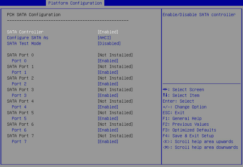
Figure 109 PCH SATA Configuration submenu screen (for the R5300)
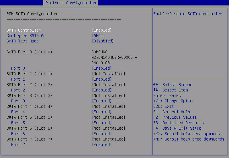
Figure 110 PCH SATA Configuration submenu screen (for the B5700, B5800, and B7800)
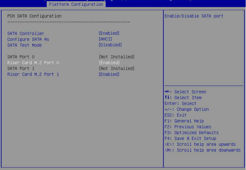
Table 64 Items on the PCH SATA Configuration submenu screen
|
Item |
Description |
Default |
|
SATA Controller |
Select Enabled or Disabled to enable or disable the SATA controller. |
Enabled |
|
Configure SATA As |
Select the operating mode of the SATA controller. Options: · AHCI—Uses the AHCI mode, which allows the drives attached to the SATA ports to be used as SATA disks. This mode supports hot swapping of drives. To use this mode, a SATA driver must be installed. · RAID—Uses the RAID mode, which allows creation of a logical drive from multiple independent physical drives. To configure the embedded RSTe RAID controller, select this option. |
AHCI |
|
SATA Test Mode |
Select Enabled or Disabled to enable or disable SATA test mode. |
Disabled |
|
SATA Port N |
Displays the name and slot number of the drive connected to logic PCH SATA port N. If no drive is connected, Not Installed is displayed. For the R4300, only SATA Port 0 and SATA Port 1 are available. For the R4400, only SATA Port 0, SATA Port 1, SATA Port 2, and SATA Port 3 are available. For the R5300, the slot number indicates the drive slot for the SATA port. |
N/A |
|
Port N |
Select Enabled or Disabled to enable or disable the drive connected to SATA port N. NOTE: For the B5700, B5800, and B7800, this field also displays the name of the component connected to the port, as shown in Figure 110. For information about the connected component for each SATA port, see Table 65. |
Enabled |
Table 65 Connected component information for each SATA port (for the B5700 and B7800)
|
SATA port |
Connected component information |
|
H3C UniServer B5700 G3 |
|
|
SATA Port 0 |
Riser Card M.2 Port 0 |
|
SATA Port 1 |
Riser Card M.2 Port 1 |
|
H3C UniServer B7800 G3 |
|
|
SATA Port 0 |
HDD Slot 0 |
|
SATA Port 1 |
HDD Slot 1 |
|
SATA Port 2 |
HDD Slot 2 |
|
SATA Port 3 |
HDD Slot 3 |
|
SATA Port 4 |
HDD Slot 4(M.2 Adapter Box Port 0) |
|
SATA Port 5 |
M.2 Adapter Box Port 1 |
|
SATA Port 6 |
Motherboard M.2 Slot 0 |
|
SATA Port 7 |
Motherboard M.2 Slot 1 |
PCH sSATA Configuration submenu screen
Figure 111 shows the PCH sSATA Configuration submenu screen. The submenu items are described in Figure 112.
Figure 111 PCH sSATA Configuration submenu screen (for all servers except for the B5700, B5800, B7800, R5300, and R8900)
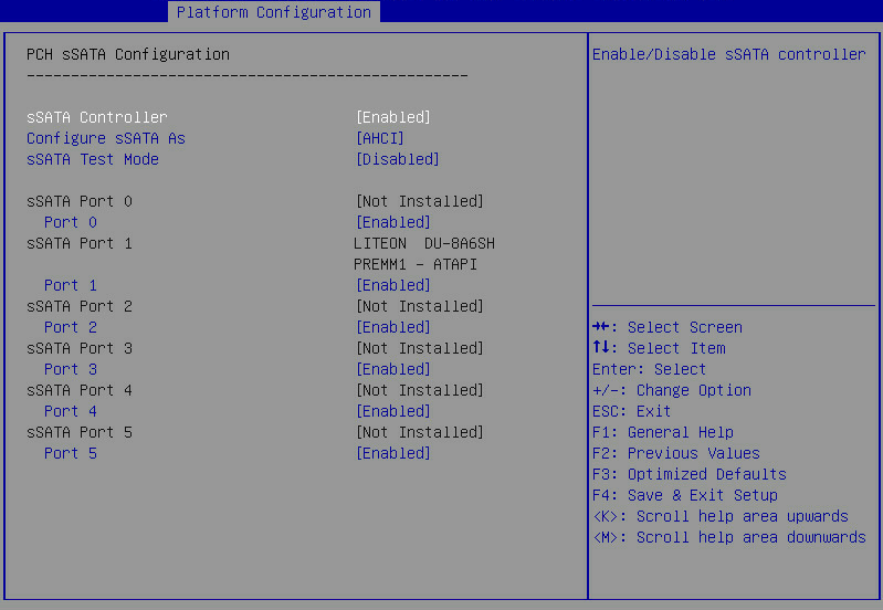
Figure 112 PCH sSATA Configuration submenu screen (for the R5300)
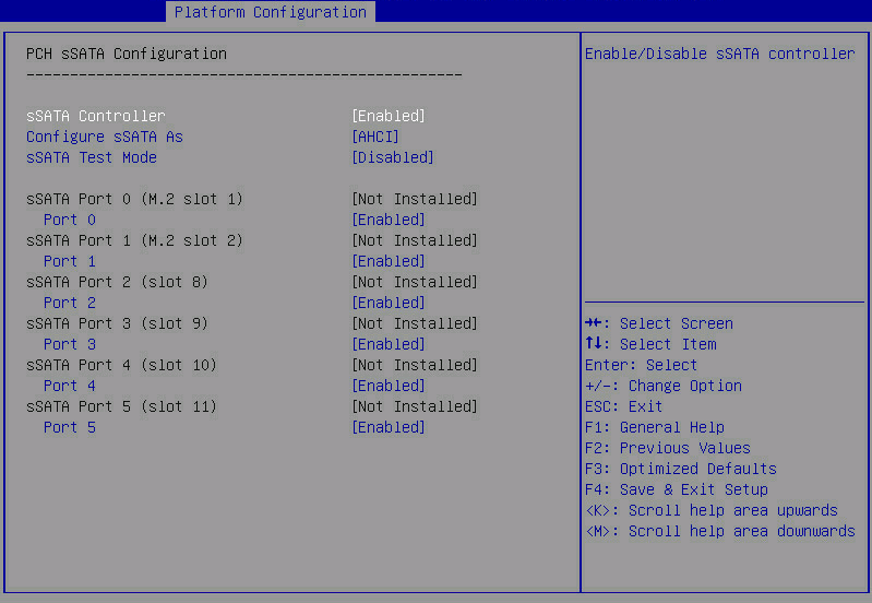
Table 66 Items on the PCH sSATA Configuration submenu screen
|
Item |
Description |
Default |
|
sSATA Controller |
Select Enabled or Disabled to enable or disable the sSATA controller. |
Enabled |
|
Configure sSATA As |
Select the operating mode of the drive controller. Options: · AHCI—Uses the AHCI mode, which allows the drives attached to the SATA ports to be used as SATA disks. This mode supports hot swapping of drives. To use this mode, a SATA driver must be installed. · RAID—Uses the RAID mode, which allows creation of a logical drive from multiple independent physical drives. To configure the embedded RSTe RAID controller, select this option. |
AHCI |
|
sSATA Test Mode |
Select Enabled or Disabled to enable or disable sSATA test mode. |
Disabled |
|
sSATA Port N |
Displays the name and the slot number of the drive connected to logic PCH sSATA port N. If no drive is connected, Not Installed is displayed. For the R5300, the slot number indicates the drive slot for the sSATA port. The number of sSATA ports varies by server model. For more information, see Table 68. |
N/A |
|
Port N |
Select Enabled or Disabled to enable or disable the drive connected to sSATA port N. NOTE: For the B5700, B5800, and B7800, this field also displays the name of the component connected to the port, as shown in Figure 110. For information about the connected component for each sSATA port, see Table 67. |
Enabled |
Table 67 Connected component information for each sSATA port (for the B5700, B5800, and B7800)
|
sSATA port |
Connected component information |
|
B5700 |
|
|
sSATA Port 0 |
HDD Slot 0 |
|
sSATA Port 1 |
HDD Slot 1 |
|
sSATA Port 2 |
HDD Slot 2(M.2 Adapter Box Port 0) |
|
sSATA Port 3 |
M.2 Adapter Box Port 1 |
|
B5800 |
|
|
sSATA Port 2 |
M.2 slot0 |
|
sSATA Port 3 |
M.2 slot1 |
|
B7800 |
|
|
sSATA Port 2 |
Riser Card M.2 Port 0 |
|
sSATA Port 3 |
Riser Card M.2 Port 1 |
Table 68 sSATA ports available for each server model
|
Server model |
sSATA ports |
|
B5700 |
See Table 67 |
|
B5800 |
See Table 67 |
|
B7800 |
See Table 67 |
|
E3200 |
Ports 0 through 5 |
|
R2700 |
Ports 0 through 5 |
|
R2900 |
Ports 0 through 5 |
|
R4300 |
Ports 0 through 5 |
|
R4400 |
N/A |
|
R4700 |
Port 5 |
|
R4900 |
Port 5 |
|
R5300 |
Ports 0 through 5 |
|
R6700 |
Ports 0 through 5 |
|
R6900 |
Ports 0 through 5 |
|
R8900 |
N/A |
USB Configuration submenu screen (for the R2700)
Figure 113 shows the USB Configuration submenu screen. The submenu items are described in Table 69.
Figure 113 USB Configuration submenu screen (for the R2700)
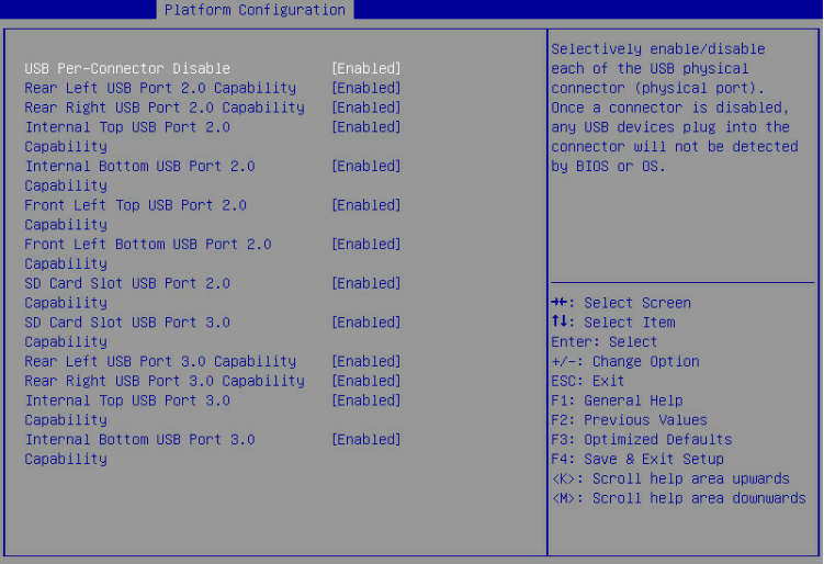
Table 69 Items on the USB Configuration submenu screen
|
Parameter |
Description |
Default |
|
USB Per-Connector Disable |
Enable or disable independent control of individual USB connectors on the system board. Options: · Enabled—You can disable the USB connectors on a per-connector basis. · Disabled—You cannot disable the USB connectors on a per-connector basis. If a USB connector is disabled, the BIOS or OS does not display the USB device plugged into that connector. NOTE: All subsequent menu items for setting USB port capability are available only if you set USB Per-Connector Disable to Enabled. |
Disabled |
|
Rear Left USB Port 2.0 Capability |
Select Enabled or Disabled to enable or disable the left USB 2.0 connector on the server's rear panel. |
Enabled |
|
Rear Right USB Port 2.0 Capability |
Select Enabled or Disabled to enable or disable the right USB 2.0 connector on the server's rear panel. |
Enabled |
|
Internal Top USB Port 2.0 Capability |
Select Enabled or Disabled to enable or disable the upper internal USB 2.0 connector. |
Enabled |
|
Internal Bottom USB Port 2.0 Capability |
Select Enabled or Disabled to enable or disable the lower internal USB 2.0 connector. |
Enabled |
|
Front Left Top USB Port 2.0 Capability |
Select Enabled or Disabled to enable or disable the upper USB 2.0 connector on the left chassis ear at the server front. |
Enabled |
|
Front Left Bottom USB Port 2.0 Capability |
Select Enabled or Disabled to enable or disable the lower USB 2.0 connector on the left chassis ear at the server front. |
Enabled |
|
SD Card Slot USB Port 2.0 Capability |
Select Enabled or Disabled to enable or disable the USB 2.0 capability of the SD card slot. |
Enabled |
|
SD Card Slot USB Port 3.0 Capability |
Select Enabled or Disabled to enable or disable the USB 3.0 capability of the SD card slot. |
Enabled |
|
Rear Left USB Port 3.0 Capability |
Select Enabled or Disabled to enable or disable the left USB 3.0 connector on the server's rear panel. |
Enabled |
|
Rear Right USB Port 3.0 Capability |
Select Enabled or Disabled to enable or disable the right USB 3.0 connector on the server's rear panel. |
Enabled |
|
Internal Top USB Port 3.0 Capability |
Select Enabled or Disabled to enable or disable the upper internal USB 3.0 connector. |
Enabled |
|
Internal Bottom USB Port 3.0 Capability |
Select Enabled or Disabled to enable or disable the lower internal USB 3.0 connector. |
Enabled |
USB Configuration submenu screen (for the R2900)
Figure 114 shows the USB Configuration submenu screen. The submenu items are described in Table 70.
Figure 114 USB Configuration submenu screen (for the R2900)
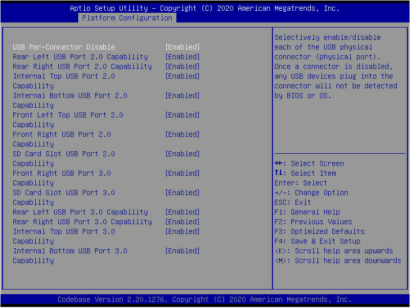
Table 70 Items on the USB Configuration submenu screen
|
Parameter |
Description |
Default |
|
USB Per-Connector Disable |
Enable or disable independent control of individual USB connectors on the system board. Options: · Enabled—You can disable the USB connectors on a per-connector basis. · Disabled—You cannot disable the USB connectors on a per-connector basis. If a USB connector is disabled, the BIOS or OS does not display the USB device plugged into that connector. NOTE: All subsequent menu items for setting USB port capability are available only if you set USB Per-Connector Disable to Enabled. |
Disabled |
|
Rear Left USB Port 2.0 Capability |
Select Enabled or Disabled to enable or disable the left USB 2.0 connector on the server's rear panel. |
Enabled |
|
Rear Right USB Port 2.0 Capability |
Select Enabled or Disabled to enable or disable the right USB 2.0 connector on the server's rear panel. |
Enabled |
|
Internal Top USB Port 2.0 Capability |
Select Enabled or Disabled to enable or disable the upper internal USB 2.0 connector. |
Enabled |
|
Internal Bottom USB Port 2.0 Capability |
Select Enabled or Disabled to enable or disable the lower internal USB 2.0 connector. |
Enabled |
|
Front Left USB Port 2.0 Capability |
Select Enabled or Disabled to enable or disable the USB 2.0 connector on the left chassis ear at the server front. |
Enabled |
|
Front Right USB Port 2.0 Capability |
Select Enabled or Disabled to enable or disable the USB 2.0 connector on the right chassis ear at the server front. |
Enabled |
|
SD Card Slot USB Port 2.0 Capability |
Select Enabled or Disabled to enable or disable the USB 2.0 capability of the SD card slot. |
Enabled |
|
Front Right USB Port 3.0 Capability |
Select Enabled or Disabled to enable or disable the USB 3.0 connector on the right chassis ear at the server front. |
Enabled |
|
SD Card Slot USB Port 3.0 Capability |
Select Enabled or Disabled to enable or disable the USB 3.0 capability of the SD card slot. |
Enabled |
|
Rear Left USB Port 3.0 Capability |
Select Enabled or Disabled to enable or disable the left USB 3.0 connector on the server's rear panel. |
Enabled |
|
Rear Right USB Port 3.0 Capability |
Select Enabled or Disabled to enable or disable the right USB 3.0 connector on the server's rear panel. |
Enabled |
|
Internal Top USB Port 3.0 Capability |
Select Enabled or Disabled to enable or disable the upper internal USB 3.0 connector. |
Enabled |
|
Internal Bottom USB Port 3.0 Capability |
Select Enabled or Disabled to enable or disable the lower internal USB 3.0 connector. |
Enabled |
USB Configuration submenu screen (for the R4300)
Figure 115 shows the USB Configuration submenu screen. The submenu items are described in Table 71.
Figure 115 USB Configuration submenu screen (for the R4300)
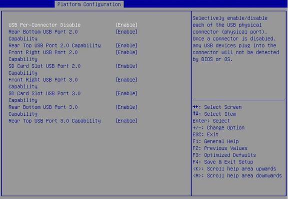
Table 71 Items on the USB Configuration submenu screen
|
Parameter |
Description |
Default |
|
USB Per-Connector Disable |
Enable or disable independent control of individual USB connectors on the system board. Options: · Enabled—You can disable the USB connectors on a per-connector basis. · Disabled—You cannot disable the USB connectors on a per-connector basis. If a USB connector is disabled, the BIOS or OS does not display the USB device plugged into that connector. NOTE: All subsequent menu items for setting USB port capability are available only if you set USB Per-Connector Disable to Enabled. |
Disabled |
|
Rear Bottom USB Port 2.0 Capability |
Select Enabled or Disabled to enable or disable the lower USB 2.0 connector on the server's rear panel. |
Enabled |
|
Rear Top USB Port 2.0 Capability |
Select Enabled or Disabled to enable or disable the upper USB 2.0 connector on the server's rear panel. |
Enabled |
|
Front Right USB Port 2.0 Capability |
Select Enabled or Disabled to enable or disable the right USB 2.0 connector on the right chassis ear at the server front. |
Enabled |
|
SD Card Slot USB Port 2.0 Capability |
Select Enabled or Disabled to enable or disable the USB 2.0 capability of the SD card slot. |
Enabled |
|
Front Right USB Port 3.0 Capability |
Select Enabled or Disabled to enable or disable the right USB 3.0 connector on the right chassis ear at the server front. |
Enabled |
|
SD Card Slot USB Port 3.0 Capability |
Select Enabled or Disabled to enable or disable the USB 3.0 capability of the SD card slot. |
Enabled |
|
Rear Bottom USB Port 3.0 Capability |
Select Enabled or Disabled to enable or disable the lower USB 3.0 connector on the server's rear panel. |
Enabled |
|
Rear Top USB Port 3.0 Capability |
Select Enabled or Disabled to enable or disable the upper USB 3.0 connector on the server's rear panel. |
Enabled |
USB Configuration submenu screen (for the R4400)
Figure 116 shows the USB Configuration submenu screen. The submenu items are described in Table 72.
Figure 116 USB Configuration submenu screen (for the R4400)
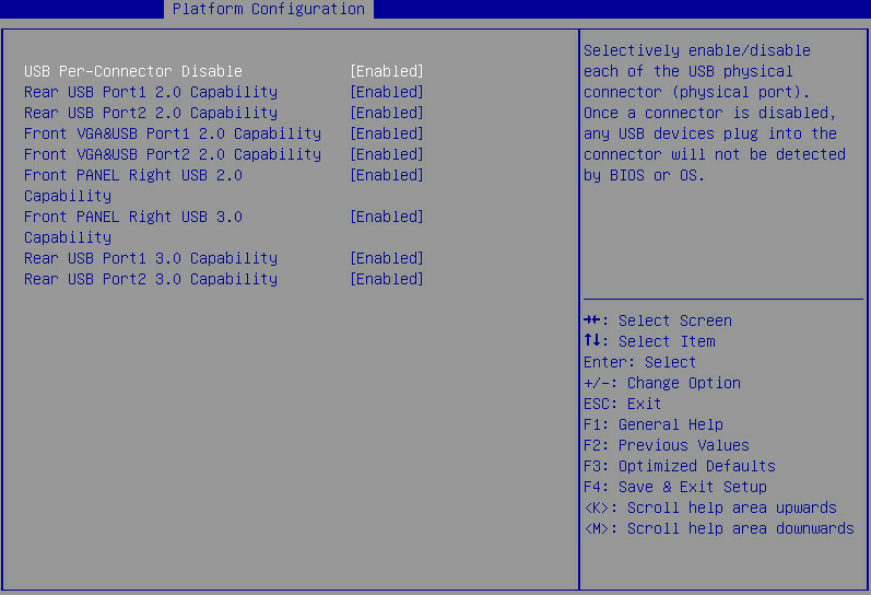
Table 72 Items on the USB Configuration submenu screen
|
Parameter |
Description |
Default |
|
USB Per-Connector Disable |
Enable or disable independent control of individual USB connectors on the system board. Options: · Enabled—You can disable the USB connectors on a per-connector basis. · Disabled—You cannot disable the USB connectors on a per-connector basis. If a USB connector is disabled, the BIOS or OS does not display the USB device plugged into that connector. NOTE: All subsequent menu items for setting USB port capability are available only if you set USB Per-Connector Disable to Enabled. |
Disabled |
|
Rear USB Port1 2.0 Capability |
Select Enabled or Disabled to enable or disable the USB 2.0 connector 1 on the server's rear panel. |
Enabled |
|
Rear USB Port2 2.0 Capability |
Select Enabled or Disabled to enable or disable the USB 2.0 connector 2 on the server's rear panel. |
Enabled |
|
Front VGA&USB Port1 2.0 Capability |
Select Enabled or Disabled to enable or disable the USB 2.0 capability of the front VGA and USB 2.0 connector 1 on the server's front panel. |
Enabled |
|
Front VGA&USB Port2 2.0 Capability |
Select Enabled or Disabled to enable or disable the USB 2.0 capability of the front VGA and USB 2.0 connector 2 on the server's front panel. |
Enabled |
|
Front PANEL Right 2.0 Capability |
Select Enabled or Disabled to enable or disable the USB 2.0 connector on the right chassis ear at the server front. |
Enabled |
|
Front PANEL Right 3.0 Capability |
Select Enabled or Disabled to enable or disable the USB 3.0 connector on the right chassis ear at the server front. |
Enabled |
|
Rear USB Port1 3.0 Capability |
Select Enabled or Disabled to enable or disable the USB 3.0 connector 1 on the server's rear panel. |
Enabled |
|
Rear USB Port2 3.0 Capability |
Select Enabled or Disabled to enable or disable the USB 3.0 connector 2 on the server's rear panel. |
Enabled |
USB Configuration submenu screen (for the R4700)
Figure 117 shows the USB Configuration submenu screen. The submenu items are described in Table 73.
Figure 117 USB Configuration submenu screen (for the R4700)
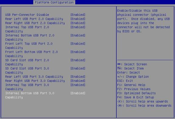
Table 73 Items on the USB Configuration submenu screen
|
Parameter |
Description |
Default |
|
USB Per-Connector Disable |
Enable or disable independent control of individual USB connectors on the system board. Options: · Enabled—You can disable the USB connectors on a per-connector basis. · Disabled—You cannot disable the USB connectors on a per-connector basis. If a USB connector is disabled, the BIOS or OS does not display the USB device plugged into that connector. NOTE: All subsequent menu items for setting USB port capability are available only if you set USB Per-Connector Disable to Enabled. |
Disabled |
|
Rear Left USB Port 2.0 Capability |
Select Enabled or Disabled to enable or disable the left USB 2.0 connector on the server's rear panel. |
Enabled |
|
Rear Right USB Port 2.0 Capability |
Select Enabled or Disabled to enable or disable the right USB 2.0 connector on the server's rear panel. |
Enabled |
|
Internal Top USB Port 2.0 Capability |
Select Enabled or Disabled to enable or disable the upper internal USB 2.0 connector. |
Enabled |
|
Internal Bottom USB Port 2.0 Capability |
Select Enabled or Disabled to enable or disable the lower internal USB 2.0 connector. |
Enabled |
|
Front Left Top USB Port 2.0 Capability |
Select Enabled or Disabled to enable or disable the upper USB 2.0 connector on the left chassis ear at the server front. |
Enabled |
|
Front Left Bottom USB Port 2.0 Capability |
Select Enabled or Disabled to enable or disable the lower USB 2.0 connector on the left chassis ear at the server front. |
Enabled |
|
SD Card Slot USB Port 2.0 Capability |
Select Enabled or Disabled to enable or disable the USB 2.0 capability of the SD card slot. |
Enabled |
|
SD Card Slot USB Port 3.0 Capability |
Select Enabled or Disabled to enable or disable the USB 3.0 capability of the SD card slot. |
Enabled |
|
Rear Left USB Port 3.0 Capability |
Select Enabled or Disabled to enable or disable the left USB 3.0 connector on the server's rear panel. |
Enabled |
|
Rear Right USB Port 3.0 Capability |
Select Enabled or Disabled to enable or disable the right USB 3.0 connector on the server's rear panel. |
Enabled |
|
Internal Top USB Port 3.0 Capability |
Select Enabled or Disabled to enable or disable the upper internal USB 3.0 connector. |
Enabled |
|
Internal Bottom USB Port 3.0 Capability |
Select Enabled or Disabled to enable or disable the lower internal USB 3.0 connector. |
Enabled |
USB Configuration submenu screen (for the R4900)
Figure 118 shows the USB Configuration submenu screen. The submenu items are described in Table 74.
Figure 118 USB Configuration submenu screen (for the R4900)
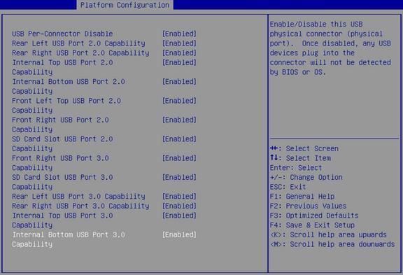
Table 74 Items on the USB Configuration submenu screen
|
Parameter |
Description |
Default |
|
USB Per-Connector Disable |
Enable or disable independent control of individual USB connectors on the system board. Options: · Enabled—You can disable the USB connectors on a per-connector basis. · Disabled—You cannot disable the USB connectors on a per-connector basis. If a USB connector is disabled, the BIOS or OS does not display the USB device plugged into that connector. NOTE: All subsequent menu items for setting USB port capability are available only if you set USB Per-Connector Disable to Enabled. |
Disabled |
|
Rear Left USB Port 2.0 Capability |
Select Enabled or Disabled to enable or disable the left USB 2.0 connector on the server's rear panel. |
Enabled |
|
Rear Right USB Port 2.0 Capability |
Select Enabled or Disabled to enable or disable the right USB 2.0 connector on the server's rear panel. |
Enabled |
|
Internal Top USB Port 2.0 Capability |
Select Enabled or Disabled to enable or disable the upper internal USB 2.0 connector. |
Enabled |
|
Internal Bottom USB Port 2.0 Capability |
Select Enabled or Disabled to enable or disable the lower internal USB 2.0 connector. |
Enabled |
|
Front Left Top USB Port 2.0 Capability |
Select Enabled or Disabled to enable or disable the upper USB 2.0 connector on the left chassis ear at the server front. |
Enabled |
|
Front Right USB Port 2.0 Capability |
Select Enabled or Disabled to enable or disable the USB 2.0 connector on the right chassis ear at the server front. |
Enabled |
|
SD Card Slot USB Port 2.0 Capability |
Select Enabled or Disabled to enable or disable the USB 2.0 capability of the SD card slot. |
Enabled |
|
Front Right USB Port 3.0 Capability |
Select Enabled or Disabled to enable or disable the USB 3.0 connector on the right chassis ear at the server front. |
Enabled |
|
SD Card Slot USB Port 3.0 Capability |
Select Enabled or Disabled to enable or disable the USB 3.0 capability of the SD card slot. |
Enabled |
|
Rear Left USB Port 3.0 Capability |
Select Enabled or Disabled to enable or disable the left USB 3.0 connector on the server's rear panel. |
Enabled |
|
Rear Right USB Port 3.0 Capability |
Select Enabled or Disabled to enable or disable the right USB 3.0 connector on the server's rear panel. |
Enabled |
|
Internal Top USB Port 3.0 Capability |
Select Enabled or Disabled to enable or disable the upper internal USB 3.0 connector. |
Enabled |
|
Internal Bottom USB Port 3.0 Capability |
Select Enabled or Disabled to enable or disable the lower internal USB 3.0 connector. |
Enabled |
USB Configuration submenu screen (for the R5300)
Figure 119 shows the USB Configuration submenu screen. The submenu items are described in Table 75.
Figure 119 USB Configuration submenu screen (for the R5300)
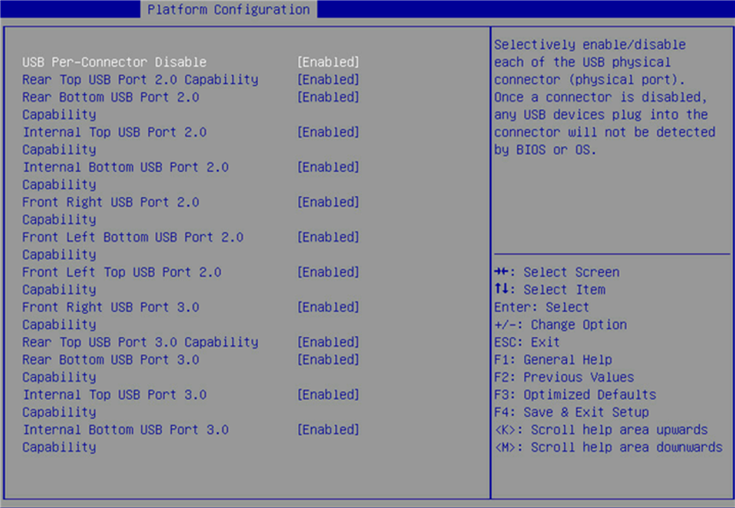
Table 75 Items on the USB Configuration submenu screen
|
Parameter |
Description |
Default |
|
USB Per-Connector Disable |
Enable or disable independent control of individual USB connectors on the system board. Options: · Enabled—You can disable the USB connectors on a per-connector basis. · Disabled—You cannot disable the USB connectors on a per-connector basis. If a USB connector is disabled, the BIOS or OS does not display the USB device plugged into that connector. NOTE: All subsequent menu items for setting USB port capability are available only if you set USB Per-Connector Disable to Enabled. |
Disabled |
|
Rear Top USB Port 2.0 Capability |
Select Enabled or Disabled to enable or disable the upper USB 2.0 connector on the server's rear panel. |
Enabled |
|
Rear Bottom USB Port 2.0 Capability |
Select Enabled or Disabled to enable or disable the lower USB 2.0 connector on the server's rear panel. |
Enabled |
|
Internal Top USB Port 2.0 Capability |
Select Enabled or Disabled to enable or disable the upper internal USB 2.0 connector. |
Enabled |
|
Internal Bottom USB Port 2.0 Capability |
Select Enabled or Disabled to enable or disable the lower internal USB 2.0 connector. |
Enabled |
|
Front Right USB Port 2.0 Capability |
Select Enabled or Disabled to enable or disable the USB 2.0 connector on the right chassis ear at the server front. |
Enabled |
|
Front Left Bottom USB Port 2.0 Capability |
Select Enabled or Disabled to enable or disable the lower USB 2.0 connector on the left chassis ear at the server front. |
Enabled |
|
Front Left Top USB Port 2.0 Capability |
Select Enabled or Disabled to enable or disable the upper USB 2.0 connector on the left chassis ear at the server front. |
Enabled |
|
Front Right USB Port 3.0 Capability |
Select Enabled or Disabled to enable or disable the USB 3.0 connector on the right chassis ear at the server front. |
Enabled |
|
Rear Top USB Port 3.0 Capability |
Select Enabled or Disabled to enable or disable the upper USB 3.0 connector on the server's rear panel. |
Enabled |
|
Rear Bottom USB Port 3.0 Capability |
Select Enabled or Disabled to enable or disable the lower USB 3.0 connector on the server's rear panel. |
Enabled |
|
Internal Top USB Port 3.0 Capability |
Select Enabled or Disabled to enable or disable the upper internal USB 3.0 connector. |
Enabled |
|
Internal Bottom USB Port 3.0 Capability |
Select Enabled or Disabled to enable or disable the lower internal USB 3.0 connector. |
Enabled |
USB Configuration submenu screen (for the R6700)
Figure 120 shows the USB Configuration submenu screen. The submenu items are described in Table 76.
Figure 120 USB Configuration submenu screen (for the R6700)
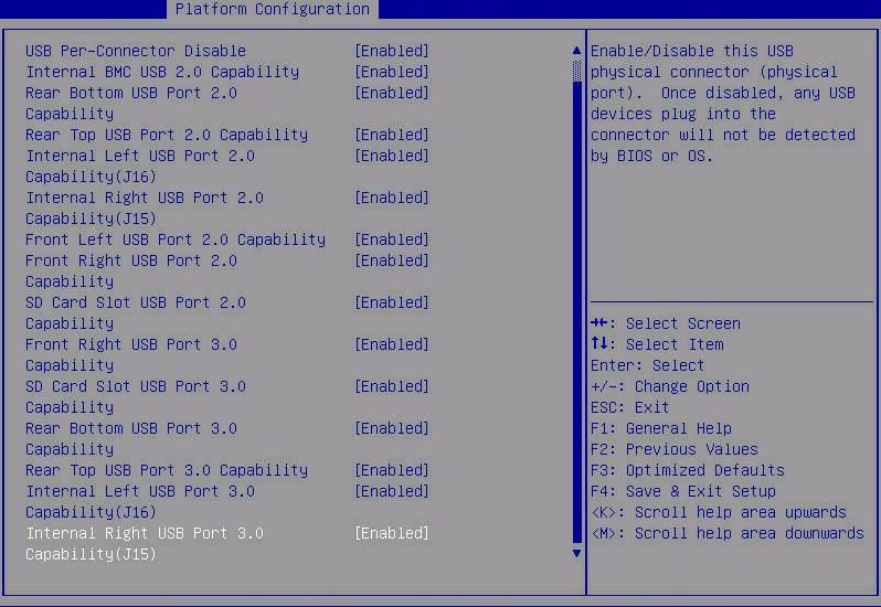
Table 76 Items on the USB Configuration submenu screen
|
Parameter |
Description |
Default |
|
USB Per-Connector Disable |
Enable or disable independent control of individual USB connectors on the system board. Options: · Enabled—You can disable the USB connectors on a per-connector basis. · Disabled—You cannot disable the USB connectors on a per-connector basis. If a USB connector is disabled, the BIOS or OS does not display the USB device plugged into that connector. NOTE: All subsequent menu items for setting USB port capability are available only if you set USB Per-Connector Disable to Enabled. |
Disabled |
|
Internal BMC USB Port 2.0 Capability |
Select Enabled or Disabled to enable or disable USB 2.0 capability of the internal BMC. |
Enabled |
|
Rear Bottom USB Port 2.0 Capability |
Select Enabled or Disabled to enable or disable the lower USB 2.0 connector on the server's rear panel. |
Enabled |
|
Rear Top USB Port 2.0 Capability |
Select Enabled or Disabled to enable or disable the upper USB 2.0 connector on the server's rear panel. |
Enabled |
|
Internal Left USB Port 2.0 Capability(J16) |
Select Enabled or Disabled to enable or disable the left internal USB 2.0 connector. |
Enabled |
|
Internal Right USB Port 2.0 Capability(J15) |
Select Enabled or Disabled to enable or disable the right internal USB 2.0 connector. |
Enabled |
|
Front Left USB Port 2.0 Capability |
Select Enabled or Disabled to enable or disable the upper USB 2.0 connector on the left chassis ear at the server front. |
Enabled |
|
Front Right USB Port 2.0 Capability |
Select Enabled or Disabled to enable or disable the USB 2.0 connector on the right chassis ear at the server front. |
Enabled |
|
SD Card Slot USB Port 2.0 Capability |
Select Enabled or Disabled to enable or disable USB 2.0 capability of the SD card slot. |
Enabled |
|
Front Right USB Port 3.0 Capability |
Select Enabled or Disabled to enable or disable the USB 3.0 connector on the server's front panel. |
Enabled |
|
SD Card Slot USB Port 3.0 Capability |
Select Enabled or Disabled to enable or disable USB 3.0 capability of the SD card slot. |
Enabled |
|
Rear Bottom USB Port 3.0 Capability |
Select Enabled or Disabled to enable or disable the lower USB 3.0 connector on the server's rear panel. |
Enabled |
|
Rear Top USB Port 3.0 Capability |
Select Enabled or Disabled to enable or disable the upper USB 3.0 connector on the server's rear panel. |
Enabled |
|
Internal Left USB Port 3.0 Capability(J16) |
Select Enabled or Disabled to enable or disable the left internal USB 3.0 connector. |
Enabled |
|
Internal Right USB Port 3.0 Capability(J15) |
Select Enabled or Disabled to enable or disable the right internal USB 3.0 connector. |
Enabled |
USB Configuration submenu screen (for the R6900)
Figure 121 shows the USB Configuration submenu screen. The submenu items are described in Table 77.
Figure 121 USB Configuration submenu screen (for the R6900)
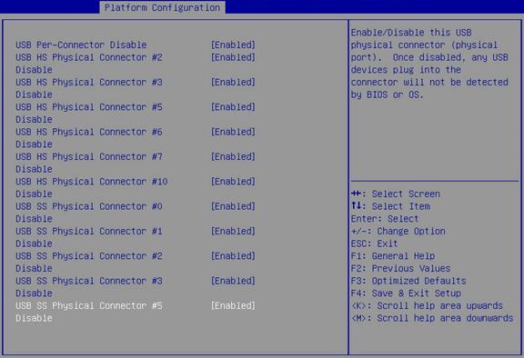
Table 77 Items on the USB Configuration submenu screen
|
Parameter |
Description |
Default |
|
USB Per-Connector Disable |
Enable or disable independent control of individual USB connectors on the system board. Options: · Enabled—You can disable the USB connectors on a per-connector basis. · Disabled—You cannot disable the USB connectors on a per-connector basis. If a USB connector is disabled, the BIOS or OS does not display the USB device plugged into that connector. NOTE: All subsequent menu items for setting USB port capability are available only if you set USB Per-Connector Disable to Enabled. |
Disabled |
|
USB HS Physical Connector #2 Disable |
Select Enabled or Disabled to enable or disable the lower USB 2.0 connector on the server's rear panel. |
Enabled |
|
USB HS Physical Connector #3 Disable |
Select Enabled or Disabled to enable or disable the upper USB 2.0 connector on the server's rear panel. |
Enabled |
|
USB HS Physical Connector #5 Disable |
Select Enabled or Disabled to enable or disable the internal USB 2.0 connector. |
Enabled |
|
USB HS Physical Connector #6 Disable |
Select Enabled or Disabled to enable or disable the upper USB 2.0 connector on the left chassis ear at the server front. |
Enabled |
|
USB HS Physical Connector #7 Disable |
Select Enabled or Disabled to enable or disable the lower USB 2.0 connector on the left chassis ear at the server front. |
Enabled |
|
USB HS Physical Connector #10 Disable |
Select Enabled or Disabled to enable or disable the USB 2.0 connector on the right chassis ear at the server front. |
Enabled |
|
USB SS Physical Connector #0 Disable |
Select Enabled or Disabled to enable or disable the USB 3.0 connector on the right chassis ear at the server front. |
Enabled |
|
USB SS Physical Connector #1 Disable |
Select Enabled or Disabled to enable or disable the USB 3.0 capability of the dual SD card extended module. |
Enabled |
|
USB SS Physical Connector #2 Disable |
Select Enabled or Disabled to enable or disable the lower USB 3.0 connector on the server's rear panel. |
Enabled |
|
USB SS Physical Connector #3 Disable |
Select Enabled or Disabled to enable or disable the upper USB 3.0 connector on the server's rear panel. |
Enabled |
|
USB SS Physical Connector #5 Disable |
Select Enabled or Disabled to enable or disable the internal USB 3.0 connector. |
Enabled |
USB Configuration submenu screen (for the R8900)
Figure 122 shows the USB Configuration submenu screen. The submenu items are described in Table 78.
Figure 122 USB Configuration submenu screen (for the R8900)
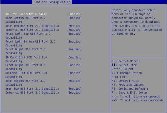
Table 78 Items on the USB Configuration submenu screen
|
Parameter |
Description |
Default |
|
USB Per-Connector Disable |
Enable or disable independent control of individual USB connectors on the system board. Options: · Enabled—You can disable the USB connectors on a per-connector basis. · Disabled—You cannot disable the USB connectors on a per-connector basis. If a USB connector is disabled, the BIOS or OS does not display the USB device plugged into that connector. NOTE: All subsequent menu items for setting USB port capability are available only if you set USB Per-Connector Disable to Enabled. |
Disabled |
|
Rear Bottom USB Port 2.0 Capability |
Select Enabled or Disabled to enable or disable the lower USB 2.0 connector on the server's rear panel. |
Enabled |
|
Rear Top USB Port 2.0 Capability |
Select Enabled or Disabled to enable or disable the upper USB 2.0 connector on the server's rear panel. |
Enabled |
|
Internal USB Port 2.0 Capability |
Select Enabled or Disabled to enable or disable the internal USB 2.0 connector. |
Enabled |
|
Front Left Top USB Port 2.0 Capability |
Select Enabled or Disabled to enable or disable the upper USB 2.0 connector on the left chassis ear at the server front. |
Enabled |
|
Front Left Bottom USB Port 2.0 Capability |
Select Enabled or Disabled to enable or disable the lower USB 2.0 connector on the left chassis ear at the server front. |
Enabled |
|
Front Right USB Port 2.0 Capability |
Select Enabled or Disabled to enable or disable the USB 2.0 connector on the right chassis ear at the server front. |
Enabled |
|
SD Card Slot USB Port 2.0 Capability |
Select Enabled or Disabled to enable or disable the USB 2.0 capability of the SD card slot. |
Enabled |
|
Front Right USB Port 3.0 Capability |
Select Enabled or Disabled to enable or disable the USB 3.0 connector on the right chassis ear at the server front. |
Enabled |
|
SD Card Slot USB Port 3.0 Capability |
Select Enabled or Disabled to enable or disable the USB 3.0 capability of the SD card slot. |
Enabled |
|
Rear Bottom USB Port 3.0 Capability |
Select Enabled or Disabled to enable or disable the lower USB 3.0 connector on the server's rear panel. |
Enabled |
|
Rear Top USB Port 3.0 Capability |
Select Enabled or Disabled to enable or disable the upper USB 3.0 connector on the server's rear panel. |
Enabled |
|
Internal USB Port 3.0 Capability |
Select Enabled or Disabled to enable or disable the internal USB 3.0 connector. |
Enabled |
USB Configuration submenu screen (for the E3200)
Figure 123 shows the USB Configuration submenu screen. The submenu items are described in Table 79.
Figure 123 USB Configuration submenu screen (for the E3200)
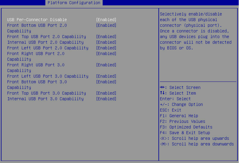
Table 79 Items on the USB Configuration submenu screen
|
Parameter |
Description |
Default |
|
USB Per-Connector Disable |
Enable or disable independent control of individual USB connectors on the system board. Options: · Enabled—You can disable the USB connectors on a per-connector basis. · Disabled—You cannot disable the USB connectors on a per-connector basis. If a USB connector is disabled, the BIOS or OS does not display the USB device plugged into that connector. NOTE: All subsequent menu items for setting USB port capability are available only if you set USB Per-Connector Disable to Enabled. |
Disabled |
|
Front Bottom USB Port 2.0 Capability |
Select Enabled or Disabled to enable or disable the lower USB 2.0 connector on the server's front panel. |
Enabled |
|
Front Top USB Port 2.0 Capability |
Select Enabled or Disabled to enable or disable the upper USB 2.0 connector on the server's front panel. |
Enabled |
|
Internal USB Port 2.0 Capability |
Select Enabled or Disabled to enable or disable the internal USB 2.0 connector. |
Enabled |
|
Front Left USB Port 2.0 Capability |
Select Enabled or Disabled to enable or disable the upper USB 2.0 connector on the left chassis ear at the server front. |
Enabled |
|
Front Right USB Port 2.0 Capability |
Select Enabled or Disabled to enable or disable the USB 2.0 connector on the right chassis ear at the server front. |
Enabled |
|
Front Right USB Port 3.0 Capability |
Select Enabled or Disabled to enable or disable the USB 3.0 connector on the right chassis ear at the server front. |
Enabled |
|
Front Left USB Port 3.0 Capability |
Select Enabled or Disabled to enable or disable the USB 3.0 connector on the left chassis ear at the server front. |
Enabled |
|
Front Bottom USB Port 3.0 Capability |
Select Enabled or Disabled to enable or disable the lower USB 3.0 connector on the server's front panel. |
Enabled |
|
Front Top USB Port 3.0 Capability |
Select Enabled or Disabled to enable or disable the upper USB 3.0 connector on the server's front panel. |
Enabled |
|
Internal USB Port 3.0 Capability |
Select Enabled or Disabled to enable or disable the internal USB 3.0 connector. |
Enabled |
USB Configuration submenu screen (for the B5700)
Figure 124 shows the USB Configuration submenu screen. The submenu items are described in Table 80.
Figure 124 USB Configuration submenu screen (for the B5700)
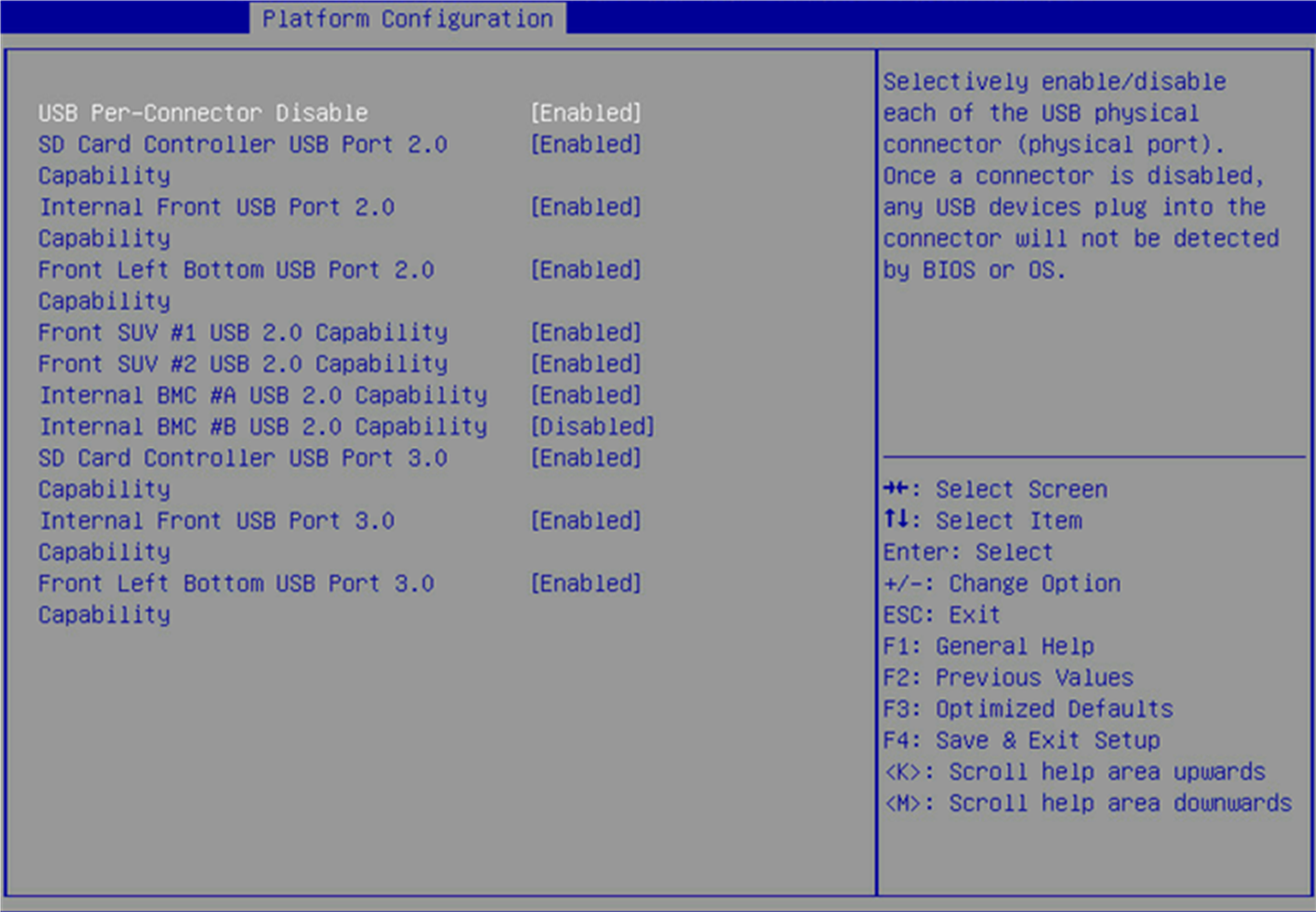
Table 80 Items on the USB Configuration submenu screen
|
Parameter |
Description |
Default |
|
USB Per-Connector Disable |
Enable or disable independent control of individual USB connectors on the system board. Options: · Enabled—You can disable the USB connectors on a per-connector basis. · Disabled—You cannot disable the USB connectors on a per-connector basis. If a USB connector is disabled, the BIOS or OS does not display the USB device plugged into that connector. NOTE: All subsequent menu items for setting USB port capability are available only if you set USB Per-Connector Disable to Enabled. |
Disabled |
|
SD Card Slot USB Port 2.0 Capability |
Select Enabled or Disabled to enable or disable the USB 2.0 capability of the SD card slot. |
Enabled |
|
Internal Front USB Port 2.0 Capability |
Select Enabled or Disabled to enable or disable the internal front USB 2.0 connector. |
Enabled |
|
Front Left Bottom USB Port 2.0 Capability |
Select Enabled or Disabled to enable or disable the lower USB 2.0 connector on the left chassis ear at the server front. |
Enabled |
|
Front SUV #1 USB Port 2.0 Capability |
Select Enabled or Disabled to enable or disable the USB 2.0 capability of SUV port #1 on the server's front panel. |
Enabled |
|
Front SUV #2 USB Port 2.0 Capability |
Select Enabled or Disabled to enable or disable the USB 2.0 capability of SUV port #2 on the server's front panel. |
Enabled |
|
Internal BMC #A USB Port 2.0 Capability |
Select Enabled or Disabled to enable or disable the USB 2.0 capability of the internal BMC port #A. |
Enabled |
|
Internal BMC #B USB Port 2.0 Capability |
Select Enabled or Disabled to enable or disable the USB 2.0 capability of the internal BMC port #B. |
Enabled |
|
SD Card Slot USB Port 3.0 Capability |
Select Enabled or Disabled to enable or disable the USB 3.0 capability of the SD card slot. |
Enabled |
|
Internal Front USB Port 3.0 Capability |
Select Enabled or Disabled to enable or disable the internal front USB 3.0 connector. |
Enabled |
|
Front Left Bottom USB Port 3.0 Capability |
Select Enabled or Disabled to enable or disable the lower USB 3.0 connector on the left chassis ear at the server front. |
Enabled |
USB Configuration submenu screen (for the B5800)
Figure 125 shows the USB Configuration submenu screen. The submenu items are described in Table 81.
Figure 125 USB Configuration submenu screen (for the B5800)
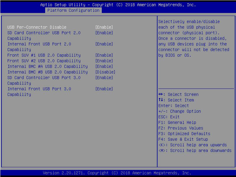
Table 81 Items on the USB Configuration submenu screen
|
Parameter |
Description |
Default |
|
USB Per-Connector Disable |
Enable or disable independent control of individual USB connectors on the system board. Options: · Enabled—You can disable the USB connectors on a per-connector basis. · Disabled—You cannot disable the USB connectors on a per-connector basis. If a USB connector is disabled, the BIOS or OS does not display the USB device plugged into that connector. NOTE: All subsequent menu items for setting USB port capability are available only if you set USB Per-Connector Disable to Enabled. |
Disabled |
|
SD Card Slot USB Port 2.0 Capability |
Select Enabled or Disabled to enable or disable the USB 2.0 capability of the SD card slot. |
Enabled |
|
Internal Front USB Port 2.0 Capability |
Select Enabled or Disabled to enable or disable the internal front USB 2.0 connector. |
Enabled |
|
Front SUV #1 USB Port 2.0 Capability |
Select Enabled or Disabled to enable or disable the USB 2.0 capability of SUV port #1 on the server's front panel. |
Enabled |
|
Front SUV #2 USB Port 2.0 Capability |
Select Enabled or Disabled to enable or disable the USB 2.0 capability of SUV port #2 on the server's front panel. |
Enabled |
|
Internal BMC #A USB Port 2.0 Capability |
Select Enabled or Disabled to enable or disable the USB 2.0 capability of the internal BMC port #A. |
Enabled |
|
Internal BMC #B USB Port 2.0 Capability |
Select Enabled or Disabled to enable or disable the USB 2.0 capability of the internal BMC port #B. |
Enabled |
|
SD Card Slot USB Port 3.0 Capability |
Select Enabled or Disabled to enable or disable the USB 3.0 capability of the SD card slot. |
Enabled |
|
Internal Front USB Port 3.0 Capability |
Select Enabled or Disabled to enable or disable the internal front USB 3.0 connector. |
Enabled |
USB Configuration submenu screen (for the B7800)
Figure 126 shows the USB Configuration submenu screen. The submenu items are described in Table 82.
Figure 126 USB Configuration submenu screen (for the B7800)
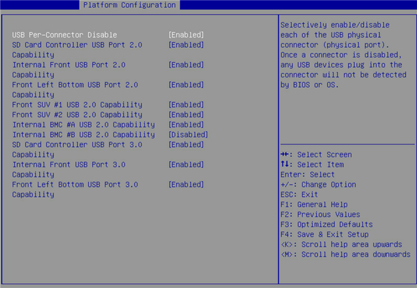
Table 82 Items on the USB Configuration submenu screen
|
Parameter |
Description |
Default |
|
USB Per-Connector Disable |
Enable or disable independent control of individual USB connectors on the system board. Options: · Enabled—You can disable the USB connectors on a per-connector basis. · Disabled—You cannot disable the USB connectors on a per-connector basis. If a USB connector is disabled, the BIOS or OS does not display the USB device plugged into that connector. NOTE: All subsequent menu items for setting USB port capability are available only if you set USB Per-Connector Disable to Enabled. |
Disabled |
|
SD Card Slot USB Port 2.0 Capability |
Select Enabled or Disabled to enable or disable the USB 2.0 capability of the SD card slot. |
Enabled |
|
Internal Front USB Port 2.0 Capability |
Select Enabled or Disabled to enable or disable the internal front USB 2.0 connector. |
Enabled |
|
Front Left Bottom USB Port 2.0 Capability |
Select Enabled or Disabled to enable or disable the lower USB 2.0 connector on the left chassis ear at the server front. |
Enabled |
|
Front SUV #1 USB Port 2.0 Capability |
Select Enabled or Disabled to enable or disable the USB 2.0 capability of SUV port #1 on the server's front panel. |
Enabled |
|
Front SUV #2 USB Port 2.0 Capability |
Select Enabled or Disabled to enable or disable the USB 2.0 capability of SUV port #2 on the server's front panel. |
Enabled |
|
Internal BMC #A USB Port 2.0 Capability |
Select Enabled or Disabled to enable or disable the USB 2.0 capability of the internal BMC port #A. |
Enabled |
|
Internal BMC #B USB Port 2.0 Capability |
Select Enabled or Disabled to enable or disable the USB 2.0 capability of the internal BMC port #B. |
Enabled |
|
SD Card Slot USB Port 3.0 Capability |
Select Enabled or Disabled to enable or disable USB 3.0 capability of the SD card slot. |
Enabled |
|
Internal Front USB Port 3.0 Capability |
Select Enabled or Disabled to enable or disable the internal front USB 3.0 connector. |
Enabled |
|
Front Left Bottom USB Port 3.0 Capability |
Select Enabled or Disabled to enable or disable the lower USB 3.0 connector on the left chassis ear at the server front. |
Enabled |
ADR Configuration submenu screen
Figure 127 shows the ADR Configuration submenu screen. The submenu items are described in Table 83.
Figure 127 ADR Configuration submenu screen
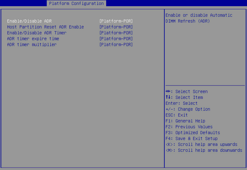
Table 83 Items on the ADR Configuration submenu screen
|
Item |
Description |
Default |
|
Enable/Disable ADR |
Select whether to enable ADR mode. Options: · Platform-POR—Automatically uses the recommended configuration. · Enabled—Enables ADR mode, which can protect memory from data loss in case of abnormal power supply. · Disabled—Disables ADR mode. |
Platform-POR |
|
Host Partition Reset ADR Enable |
Select whether to enable ADR on host paritition reset. Options: · Platform-POR—Automatically uses the recommended configuration. · Enabled—Enables ADR on host paritition reset. · Disabled—Disables ADR on host paritition reset. |
Platform-POR |
|
Enable/Disable ADR Timer |
Select whether to enable ADR timer. Options: · Platform-POR—Automatically uses the recommended configuration. · Enabled—Enables ADR timer. · Held-off—Disables ADR timer. |
Platform-POR |
|
ADR timer expire time |
Set the expiration time of the ADR timer. Options: · Platform-POR—Automatically uses the recommended expiration time. · 25us. · 50us. · 100us. · 0us. |
Platform-POR |
|
ADR timer multiplier |
Set the ADR timer multiplier. Options: · Platform-POR—Automatically uses the recommended value. · ×1. · ×8. · ×24. · ×40. · ×56. · ×64. · ×72. · ×80. · ×88. · ×96. |
Platform-POR |
Miscellaneous Configuration submenu
Figure 128 shows the Miscellaneous Configuration submenu screen, on which you can configure features described in Table 84.
Figure 128 Miscellaneous Configuration submenu screen
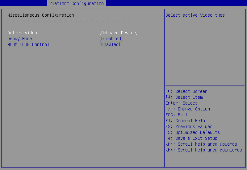
Table 84 Items on the Miscellaneous Configuration submenu screen
|
Item |
Description |
Default |
|
Active Video |
This item is unavailable for the B5700, B5800, and B7800. Select a monitor to display videos. Options: · Auto—Enables the server to automatically select a monitor to display videos. · Onboard Device—Uses the monitor connected to the onboard VGA connector to display videos. · PCIe Device—Uses the monitor connected to the GPU module in the PCIe slot to display videos. NOTE: In legacy boot mode, the server cannot display the BIOS menus on the monitor connected to the GPU module or VGA connector if the Onboard Device or PCIe Device option is selected, respectively. |
Onboard Device |
|
Debug Mode |
Select Enabled or Disabled to enable or disable outputting the debug log from a BIOS serial port. If debug mode is enabled, you can obtain the debug log by connecting to a BIOS serial port. |
Disabled |
|
MLOM LLDP Control |
This item is available only for the R2700, R2900, R4700, R4900, and R6900. Select Enabled or Disabled to enable or disable LLDP for the mLOM Ethernet adapter. LLDP enables devices of different vendors on a network to discover and exchange the system and configuration information. If LLDP is enabled, the mLOM Ethernet adapter neither send nor receive LLDP packets. |
Enabled |
Server ME Configuration submenu
Figure 129 and Figure 130 show the Server ME Configuration submenu screen, on which you can view the server management engine information described in Table 85.
Figure 129 Server ME Configuration submenu screen (1)
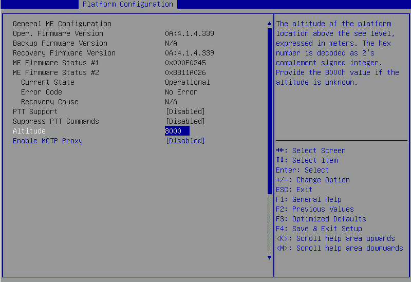
Figure 130 Server ME Configuration submenu screen (2)
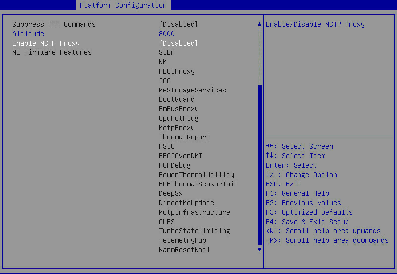
Table 85 Items on the Server ME Configuration submenu screen
|
Item |
Description |
Default |
|
Oper. Firmware Version |
Displays the active firmware version. |
N/A |
|
Backup Firmware Version |
Displays the backup firmware version. |
N/A |
|
Recovery Firmware Version |
Displays the recovery firmware version. |
N/A |
|
ME Firmware Status #1 |
Displays ME firmware status #1. |
N/A |
|
ME Firmware Status #2 |
Displays ME firmware status #2. |
N/A |
|
Current State |
Displays the current ME state. |
N/A |
|
Error Code |
Displays the error code. |
N/A |
|
Recovery Cause |
Displays the reason for recovery. |
N/A |
|
PTT Support |
Display support for the Platform Trusted Technology (PTT). |
N/A |
|
Altitude |
Set the altitude at which the server is located, a hexadecimal value in meters. The default is 8000 meters (or 26246.72 ft). |
8000 |
|
Enable MCTP Proxy |
Select Enabled or Disabled to enable or disable MCTP proxy. |
Disabled |
|
MCTP Bus Owner |
Displays the Management Component Transport Protocol (MCTP) bus owner location on PCIe. The field value is a four-bit hexadecimal number and can indicate the bus, device, and function if converted to binary format. In binary format, the high-order 9th to 16th bits indicate the bus number, 4th to 8th bits indicate the device number, and 1st to 3rd bits indicate the function. If the item is set to 0, the MCTP bus owner feature is disabled. |
0 |
|
ME Firmware Features |
Displays the ME firmware features. |
N/A |
Runtime Error Logging submenu
Figure 131 shows the Runtime Error Logging submenu screen, on which you can configure the runtime error logging as described in Table 86.
Figure 131 Runtime Error Logging submenu screen
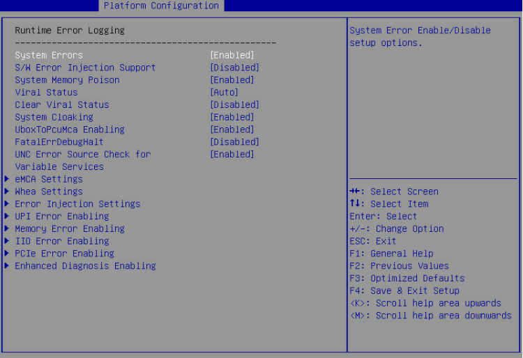
Table 86 Items on the Runtime Error Logging submenu screen
|
Item |
Description |
Default |
|
System Errors |
This item controls system error logging, which enables the server to correct system errors automatically and report uncorrectable errors to HDM and the operating system. Select Enabled or Disabled to enable or disable system error logging. |
Enabled |
|
S/W Error Injection Support |
This item is available only when System Errors is set to Enabled. Software error injection tests system performance by injecting software errors. To test system performance, select Enabled. |
Disabled |
|
System Memory Poison |
This item is available only when System Errors is set to Enabled. Select Enabled or Disabled to enable or disable system memory poison. To report event logs to HDM when uncorrectable memory errors are injected, you must set both System Memory Poison and Viral Status to Disabled. |
Enabled |
|
Viral Status |
This item is available only when System Errors is set to Enabled. This item is inaccessible if the process does not support advanced RSA. Options: · Auto—Enables the system to determine whether to enable detection of memory-resident viruses based on CPU and memory conditions. · Enabled—Enables detection of memory-resident viruses. · Disabled—Disables detection of memory-resident viruses. To report event logs to HDM when uncorrectable memory errors are injected, you must set both System Memory Poison and Viral Status to Disabled. |
Auto |
|
Clear Viral Status |
This item is unavailable when Viral Status or System Errors is set to Disabled. Select Enabled or Disabled to enable or disable the clear viral status feature. |
Disabled |
|
System Cloaking |
This item is available only when System Errors is set to Enabled. System cloaking enables the operating system and software to block corrected errors and uncorrected no action required (UCNA) errors. Select Enabled or Disabled to enable or disable system cloaking. |
Enabled |
|
UboxToPcuMca Enabling |
This item is available only when System Errors is set to Enabled. Select Enabled or Disabled to enable or disable the server to report Ubox errors to Machine Check Architecture (MCA). |
Enabled |
|
FatalErrDebugHalt |
This item is available only when System Errors is set to Enabled, and this feature is applicable only to McBank fatal error debugging. Select Enabled or Disabled to enable or disable halting fatal error debugging. Enable this feature only in conjunction with Intel® Technology Provider (ITP) because a thread will halt in fatal error flow. |
Disabled |
|
UNC Error Source Check for Variable Services |
Select Enabled or Disabled to enable or disable uncorrectable error source check for variable services. Enabling this feature will decrease the SMI latency for variable services. |
Enabled |
|
eMCA Settings |
This item is available only when System Errors is set to Enabled. Access the submenu for configuring the Enhanced Machine Check Architecture (eMCA), as shown in Figure 132. The submenu items are described in Table 87. |
N/A |
|
Whea Settings |
This item is available only when System Errors is set to Enabled. Access the submenu for configuring the Windows Hardware Error Architecture (WHEA), as shown in Figure 133. The submenu items are described in Table 88. |
N/A |
|
Error Injection Settings |
This item is available only when System Errors is set to Enabled. Access the submenu for configuring error injection settings, as shown in Figure 134. The submenu items are described in Table 89. |
N/A |
|
UPI Error Enabling |
This item is configurable only when the processors support the Advanced RAS feature. This item is available only when System Errors is set to Enabled. Access the submenu for configuring UltraPath Interconnect (UPI) error reporting, as shown in Figure 135. The submenu items are described in Table 90. |
N/A |
|
Memory Error Enabling |
This item is available only when System Errors is set to Enabled. Access the submenu for configuring memory error reporting, as shown in Figure 136. The submenu items are described in Table 91. |
N/A |
|
IIO Error Enabling |
This item is available only when System Errors is set to Enabled. Access the submenu for configuring Integrated I/O module (IIO) error reporting, as shown in Figure 137 and Figure 138. The submenu items are described in Table 92. |
N/A |
|
PCIe Error Enabling |
This item is available only when System Errors is set to Enabled. Access the submenu for configuring PCIe error reporting, as shown in Figure 139. The submenu items are described in Table 93. |
N/A |
|
Enhanced Diagnosis Enabling |
This item is available only when System Errors is set to Enabled. Access the submenu for configuring enhanced diagnosis reporting, as shown in Figure 140. The submenu items are described in Table 94. |
N/A |
eMCA Settings submenu screen
Figure 132 shows the eMCA Settings submenu screen. The submenu items are described in Table 87.
Figure 132 eMCA Settings submenu screen
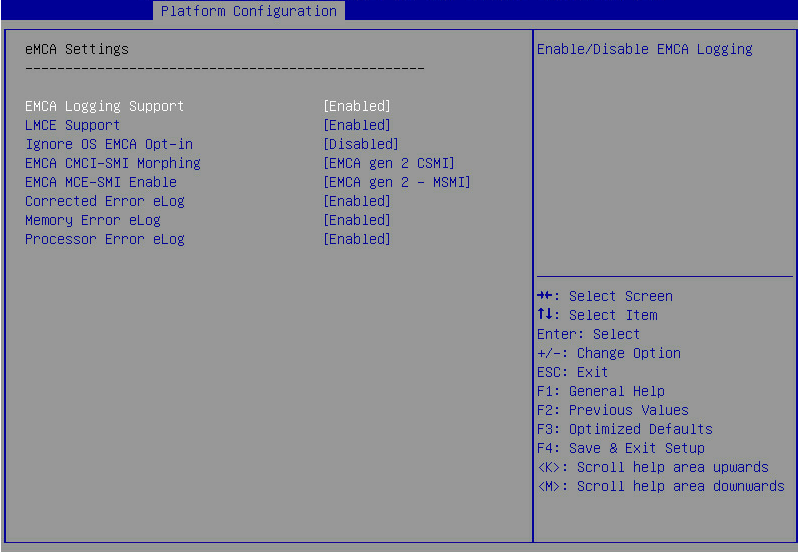
Table 87 Items on the EMCA Settings submenu screen
|
Item |
Description |
Default |
|
EMCA Logging Support |
Select Enabled or Disabled to enable or disable EMCA logging. EMCA logging provides MAC error reports for the server. |
Enabled |
|
LMCE Support |
Local machine check exceptions (LMCE) support enables the system to log detected hardware errors in firmware registers. Select Enabled or Disabled to enable or disable LMCE support. |
Enabled |
|
Ignore OS EMCA Opt-in |
This item is available only when System Errors is set to Enabled. Select Enabled or Disabled to enable or disable the ignore OS EMCA opt-in feature. |
Disabled |
|
EMCA CMCI-SMI Morphing |
This item is available only when EMCA Logging Support is set to Enabled. When EMCA CMCI-SMI morphing is enabled: · The SMI is triggered each time a correctable error occurs. · If the number of correctable errors on the MCBank exceeds the upper limit, the SMI is triggered but the Corrected Machine Check Interrupt (CMCI) is not. Options: · EMCA gen 1 Lite—Enables EMCA CMCI-SMI morphing in EMCA gen 1 lite mode. · EMCA gen 2 CSMI—Enables EMCA CMCI-SMI morphing in EMCA gen 2 CSMI mode. · Disabled—Disables EMCA CMCI-SMI morphing. |
EMCA gen 2 CSMI |
|
EMCA MCE-SMI Enable |
This item is available only when EMCA Logging Support is set to Enabled. Options: · EMCA gen 1 Dual Mode—Enables EMCA MCE-SMI in EMCA gen1 dual mode. · EMCA gen 2 – MSMI—Enables EMCA MCE-SMI in EMCA gen 2 MSMI mode. · Disabled—Disables EMCA MCE-SMI. |
EMCA gen 2 – MSMI |
|
Corrected Error eLog |
This item is available only when EMCA Logging Support is set to Enabled. Select Enabled or Disabled to enable or disable eMCA correctable error logging. |
Enabled |
|
Memory Error eLog |
This item is available only when EMCA Logging Support is set to Enabled. Select Enabled or Disabled to enable or disable eMCA memory error logging. |
Enabled |
|
Processor Error eLog |
This item is available only when EMCA Logging Support is set to Enabled. Select Enabled or Disabled to enable or disable eMCA processor error logging. |
Enabled |
Whea Settings submenu screen
Figure 133 shows the Whea Settings submenu screen. The submenu items are described in Table 88.
Figure 133 Whea Settings submenu screen
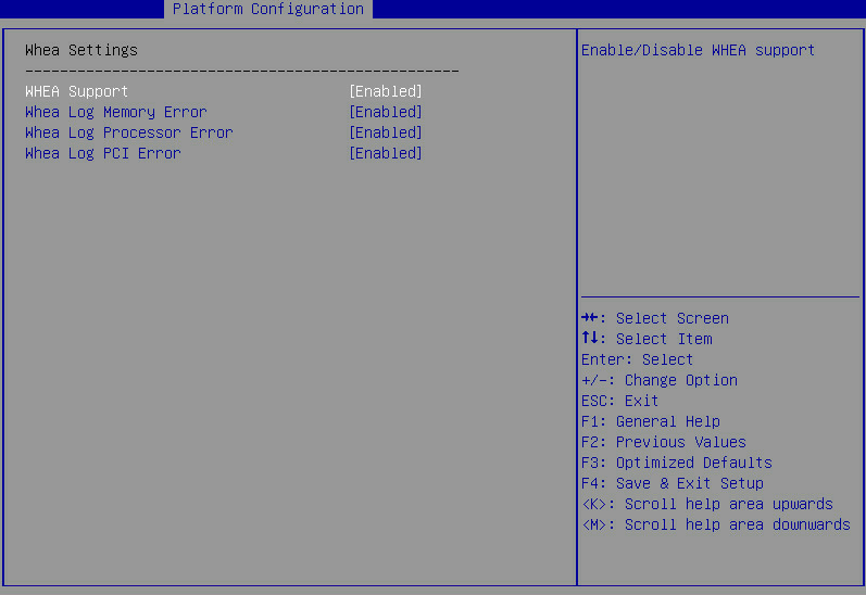
Table 88 Items on the Whea Settings submenu screen
|
Item |
Description |
Default |
|
WHEA Support |
Select Enabled or Disabled to enable or disable WHEA. WHEA provides hardware error reports for the server. |
Enabled |
|
Whea Log Memory Error |
Select Enabled or Disabled to enable or disable WHEA memory error logging. |
Enabled |
|
Whea Log Processor Error |
Select Enabled or Disabled to enable or disable WHEA processor error logging. |
Enabled |
|
Whea Log PCI Error |
Select Enabled or Disabled to enable or disable WHEA PCI error logging. |
Enabled |
Error Injection Settings submenu screen
Figure 134 shows the Error Injection Settings submenu screen. The submenu items are described in Table 89.
Figure 134 Error Injection Settings submenu screen
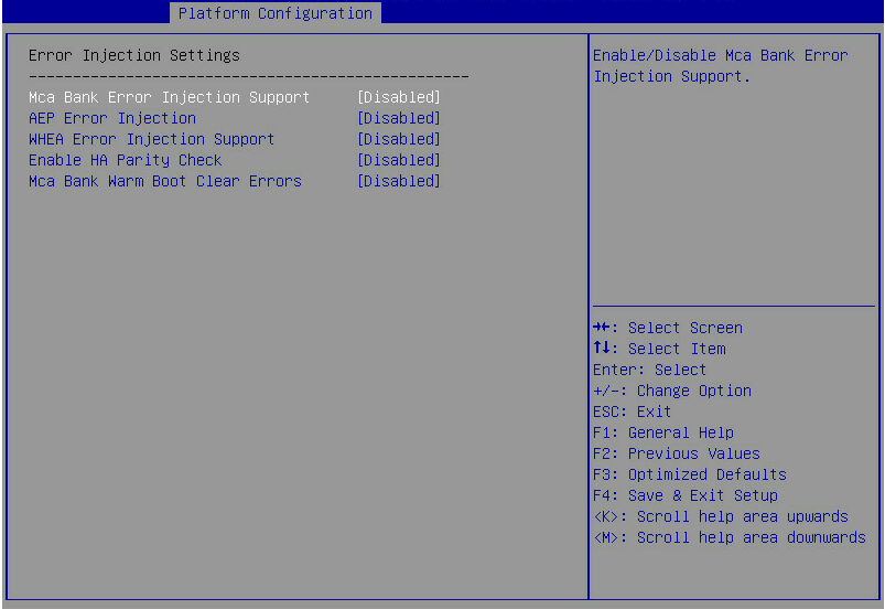
Table 89 Items on the Error Injection Settings submenu screen
|
Item |
Description |
Default |
|
Mca Bank Error Injection Support |
This item is available only when System Errors is set to Enabled. Select Enabled or Disabled to enable or disable MCA bank error injection. If MCA bank error injection is enabled, the write function of the register into which errors are injected is enabled. |
Disabled |
|
AEP Error Injection |
Select Enabled or Disabled to enable or disable Apache Pass (AEP) error injection. |
Disabled |
|
WHEA Error Injection Support |
Select Enabled or Disabled to enable or disable WHEA error injection. |
Disabled |
|
WHEA Error Injection 5.0 Support Extension |
This item is available only when WHEA Error Injection Support is set to Enabled. Select Enabled or Disabled to enable or disable support for WHEA error injection 5.0 extension. If support for WHEA error injection 5.0 extension is enabled, the error type can carry address and vendor extensions. |
Enabled |
|
Whea PCIE Error Injection Support |
This item is available only when WHEA Error Injection Support is set to Enabled. Select Enabled or Disabled to enable or disable WHEA PCIe error injection. |
Disabled |
|
Whea PCIe Error Injection Action Table |
This item is available only when WHEA Error Injection Support is set to Enabled. Select Enabled or Disabled to enable or disable WHEA PCIe error injection action table. |
Enabled |
|
Enable HA Parity Check |
Select Enabled or Disabled to enable or disable HA parity check. |
Disabled |
|
Mca Bank Warm Boot Clear Errors |
Select Enabled or Disabled to enable or disable MCA bank error clearing upon a warm reset. |
Disabled |
UPI Error Enabling submenu screen
Figure 135 shows the UPI Error Enabling submenu screen. The submenu items are described in Table 90.
Figure 135 UPI Error Enabling submenu screen
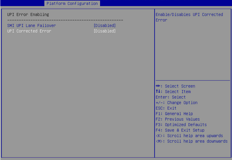
Table 90 Items on the UPI Error Enabling submenu screen
|
Item |
Description |
Default |
|
SMI UPI Lane Failover |
Select Enabled or Disabled to enable or disable triggering an SMI upon a UPI lane failover. |
Disabled |
|
UPI Corrected Error |
Select Enabled or Disabled to enable or disable reporting UPI correctable errors to HDM. |
Disabled |
Memory Error Enabling submenu screen
Figure 136 shows the Memory Error Enabling submenu screen. The submenu items are described in Table 91.
Figure 136 Memory Error Enabling submenu screen
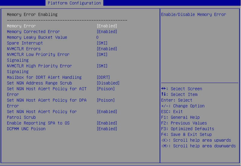
Table 91 Items on the Memory Error Enabling submenu screen
|
Item |
Description |
Default |
|
Memory Error |
Select Enabled or Disabled to enable or disable memory error reporting. |
Enabled |
|
Memory Corrected Error |
This item is available only when Memory Corrected Error is set to Enabled. Select Enabled or Disabled to enable or disable correctable memory error reporting. |
Enabled |
|
Memory Leaky Bucket Value |
This item is available only when Memory Corrected Error is set to Enabled. Set the memory leaky bucket value in hexadecimal notation. Value range: 0x0000 to 0xffff. |
0 |
|
Spare Interrupt |
This item is available only when Memory Corrected Error is set to Enabled. Select the type of the spare interrupt to generate upon detection of a memory error. Options: · Disabled—Disables spare interrupt generation. · SMI—Generates an SMI interrupt. · Error Pin—Generates an error pin interrupt. · CMCI—Generates a CMCI interrupt. |
SMI |
|
NVMCTLR Errors |
This item is available only when Memory Corrected Error is set to Enabled. Select Enabled or Disabled to enable or disable NVMCTLR error logging and reporting. |
Enabled |
|
NVMCTLR Low Priority Error Signaling |
This item is available only when Memory Corrected Error is set to Enabled. Set NVMCTLR low priority error signaling. Options: · Disabled—Disables reporting of NVMCTLR low priority errors. · SMI—Uses SMI interrupts to send NVMCTLR low priority error signals. · ERRO# Pin—Uses ERRO# Pin to send NVMCTLR low priority error signals. |
SMI |
|
NVMCTLR High Priority Error Signaling |
This item is available only when Memory Corrected Error is set to Enabled. Set NVMCTLR high priority error signaling configuration. Options: · Disabled—Disables reporting of NVMCTLR high priority errors. · SMI—Uses SMI interrupts to send NVMCTLR high priority error signals. · ERRO# Pin—Uses ERRO# Pin to send NVMCTLR high priority error signals. |
SMI |
|
Mailbox for DDRT Alert Handling |
This item is available only when Memory Corrected Error is set to Enabled. Select the method for the mailbox to handle DDRT alerts. Options: · DDRT—Uses DDRT to handle alerts. · SMBUS—Uses System Management Bus (SMBus) to handle alerts. This option is only available for verification. |
DDRT |
|
Set NGN Address Range Scrub |
This item is available only when Memory Corrected Error is set to Enabled. Select Enabled or Disabled to enable or disable NGN DIMM physical address range scrubbing. |
Disabled |
|
Set NGN Host Alert Policy for AIT Error |
This item is configurable only when the processors support the Advanced RAS feature. This item is available only when Memory Corrected Error is set to Enabled. Set the signal type for the received address indirection table (AIT) errors. Options are Poison and Viral. |
Poison |
|
Set NGN Host Alert Policy for DPA Error |
This item is configurable only when the processors support the Advanced RAS feature. Set the signal type for the received DIMM physical address (DPA) errors. Options are Poison and Viral. |
Poison |
|
Set NGN Host Alert Policy for Patrol Scrub |
This item is configurable only when the processors support the Advanced RAS feature. This item is available only when Memory Corrected Error is set to Enabled. Select Enabled or Disabled to enable or disable the patrol scrubbing error alert policy. With the policy enabled, the system triggers DDRT interrupts based on uncorrectable errors detected by NGN patrol scrubbing. |
Enabled |
|
Enable Reporting SPA to OS |
This item is available only when Memory Corrected Error is set to Enabled. Select Enabled or Disabled to enable or disable system physical address (SPA) reporting to the operating system. If the reporting is enabled, the MCE recovery threshold is disabled. |
Enabled |
|
DCPMM UNC Poison |
Select whether to enable the poison mode for Intel DCPMMs. Options: · Enabled—When an uncorrectable error is detected in an Intel DCPMM, the DCPMM marks the abnormal data as poison and then continues to transmit the data. · Disabled—When an uncorrectable error is detected in an Intel DCPMM, the DCPMM directly reports the error. |
Enabled |
IIO Error Enabling submenu screen
Figure 137 and Figure 138 show the IIO Error Enabling submenu screen. The submenu items are described in Table 92.
Figure 137 IIO Error Enabling submenu screen (1)
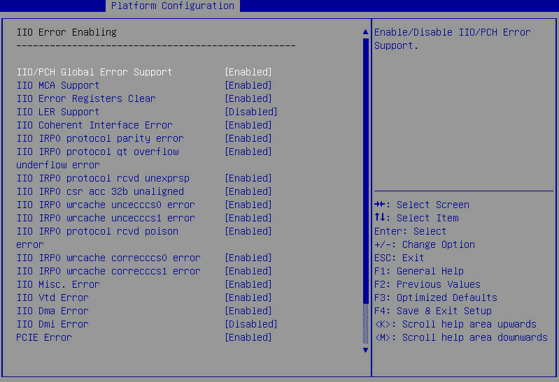
Figure 138 IIO Error Enabling submenu screen (2)
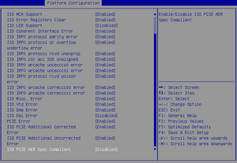
Table 92 Items on the IIO Error Enabling submenu screen
|
Item |
Description |
Default |
|
IIO/PCH Global Error Support |
Select Enabled or Disabled to enable or disable IIO/PCH global error reporting. |
Enabled |
|
IIO MCA Support |
Select Enabled or Disabled to enable or disable IIO MCA support. |
Enabled |
|
IIO Error Pin Programming |
This item is available only when IIO LER Support is set to Enabled. Select Enabled or Disabled to enable or disable IIO error register. |
Enabled |
|
IIO Error Registers Clear |
Select Enabled or Disabled to enable or disable clearing IIO error registers. |
Enabled |
|
IIO LER Support |
This item is configurable only when the processors support the Advanced RAS feature. Select Enabled or Disabled to enable or disable IIO LER support. |
Disabled |
|
LER MA Error Logging |
This item is available only when IIO LER Support is set to Enabled. Select Enabled or Disabled to disable or enable PCIe MCA error logging. |
|
|
IIO Coherent Interface Error |
Select Enabled or Disabled to enable or disable IIO coherent interface error detection. |
Enabled |
|
IIO IRP0 protocol parity error |
This item is configurable only when IIO Coherent Interface Error is set to Enabled. Select Enabled or Disabled to enable or disable IIO IRP0 protocol parity error detection. |
Enabled |
|
IIO IRP0 protocol qt overflow underflow error |
This item is configurable only when IIO Coherent Interface Error is set to Enabled. Select Enabled or Disabled to enable or disable the IIO coherent interface protocol layer queue table overflow or underflow error reporting. |
Enabled |
|
IIO IRP0 protocol rcvd unexprsp |
This item is configurable only when IIO Coherent Interface Error is set to Enabled. Select Enabled or Disabled to enable or disable IIO coherent interface protocol layer received unexpected response or completion error reporting. |
Enabled |
|
IIO IRP0 csr acc 32b unaligned |
This item is configurable only when IIO Coherent Interface Error is set to Enabled. Select Enabled or Disabled to enable or disable IIO coherent interface CSR access crossing 32-bit boundary error reporting. |
Enabled |
|
IIO IRP0 wrcache uncecccs0 error |
This item is configurable only when IIO Coherent Interface Error is set to Enabled. Select Enabled or Disabled to enable or disable reporting of IIO coherent interface write cache uncorrectable ECC errors. |
Enabled |
|
IIO IRP0 wrcache uncecccs1 error |
This item is configurable only when IIO Coherent Interface Error is set to Enabled. Select Enabled or Disabled to enable or disable reporting of IIO coherent interface write cache uncorrectable ECC errors. |
Enabled |
|
IIO IRP0 protocol rcvd poison error |
This item is configurable only when IIO Coherent Interface Error is set to Enabled. Select Enabled or Disabled to enable or disable reporting of IIO coherent interface protocol layer received poisoned packet errors. |
Enabled |
|
IIO IRP0 wrcache correcccs0 error |
This item is configurable only when IIO Coherent Interface Error is set to Enabled. Select Enabled or Disabled to enable or disable reporting of IIO coherent interface write cache correctable ECC errors. |
Enabled |
|
IIO IRP0 wrcache correcccs1 error |
This item is configurable only when IIO Coherent Interface Error is set to Enabled. Select Enabled or Disabled to enable or disable reporting of IIO coherent interface write cache correctable ECC errors. |
Enabled |
|
IIO Misc. Error |
Select Enabled or Disabled to enable or disable miscellaneous IIO error detection. |
Enabled |
|
IIO Vtd Error |
Select Enabled or Disabled to enable or disable IIO Vtd error detection. |
Enabled |
|
IIO Dma Error |
Select Enabled or Disabled to enable or disable IIO DMA error detection. |
Enabled |
|
IIO Dmi Error |
Select Enabled or Disabled to enable or disable IIO DMI error detection. |
Disabled |
|
PCIE Error |
Select Enabled or Disabled to enable or disable PCIe error detection. |
Enabled |
|
IIO PCIE Additional Corrected error |
Select Enabled or Disabled to enable or disable IIO PCIe additional correctable error detection. |
Enabled |
|
IIO PCIE Additional Uncorrected error |
Select Enabled or Disabled to enable or disable IIO PCIe additional uncorrectable error detection. |
Enabled |
|
IIO PCIe AER Spec Compliant |
Select Enabled or Disabled to enable or disable IIO PCIe Advanced Error Reporting (AER) specification compliance checking. If this feature is enabled, poisoned errors are recorded as fatal errors. If this feature is disabled, poisoned errors are recorded as non-fatal errors. |
Disabled |
PCIe Error Enabling submenu screen
Figure 139 shows the PCIe Error Enabling submenu screen. The submenu items are described in Table 93.
Figure 139 PCIe Error Enabling submenu screen
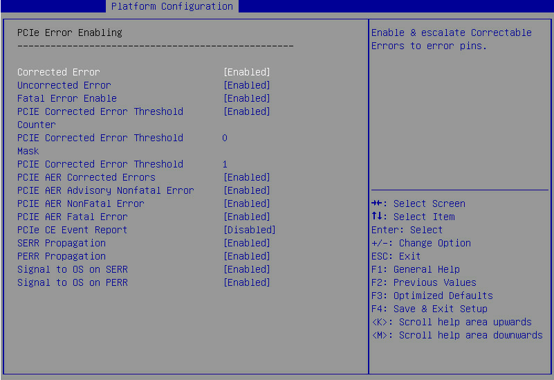
Table 93 Items on the PCIe Error Enabling submenu screen
|
Items |
Description |
Default |
|
Corrected Error |
Select Enabled or Disabled to enable or disable PCIe correctable error reporting. |
Enabled |
|
Uncorrected Error |
Select Enabled or Disabled to enable or disable PCIe uncorrectable error reporting. |
Enabled |
|
Fatal Error Enable |
Select Enabled or Disabled to enable or disable PCIe fatal error reporting. |
Enabled |
|
PCIe Corrected Error Threshold Counter |
Select Enabled or Disabled to enable or disable the PCIe correctable error threshold counter. |
Enabled |
|
PCIe Corrected Error Threshold Mask |
This item is configurable only when PCIe Corrected Error Threshold Counter is set to Enabled. Set the PCIe correctable error threshold mask. |
0 |
|
PCIE Correctable Error Threshold |
This item is configurable only when PCIe Corrected Error Threshold Counter is set to Enabled. Set the PCIe correctable error threshold. |
1 |
|
PCIE AER Corrected Errors |
Select Enabled or Disabled to enable or disable PCIe AER correctable error detection. |
Enabled |
|
PCIE AER Advisory Nonfatal Error |
Select Enabled or Disabled to enable or disable PCIe AER advisory non-fatal error detection. |
Enabled |
|
PCIE AER NonFatal Error |
Select Enabled or Disabled to enable or disable PCIe AER non-fatal error detection. |
Enabled |
|
PCIE AER Fatal Error |
Select Enabled or Disabled to enable or disable PCIe AER fatal error detection. |
Enabled |
|
PCIe CE Event Report |
Select Enabled or Disabled to enable or disable reporting PCIe correctable errors to System Event Log (SEL). |
Disabled |
|
SERR Propagation |
Select Enabled or Disabled to enable or disable SERR propagation. |
Enabled |
|
PERR Propagation |
Select Enabled or Disabled to enable or disable PERR propagation. |
Enabled |
|
Signal to OS on SERR |
Select Enabled or Disabled to enable or disable reporting SERR signals to the operating system. |
Enabled |
|
Signal to OS on PERR |
Select Enabled or Disabled to enable or disable reporting PERR signals to the operating system. |
Enabled |
Enhanced Diagnosis Enabling submenu screen
Figure 140 shows the Enhanced Diagnosis Enabling submenu screen. The submenu items are described in Table 94.
Figure 140 Enhanced Diagnosis Enabling submenu screen

Table 94 Items on the Enhanced Diagnosis Enabling submenu screen
|
Items |
Description |
Default |
|
Enhanced Diagnosis Module |
Select Enabled or Disabled to enable or disable the enhanced diagnosis module. |
Enabled |
|
PCIe SEL Info Level |
This item is configurable only when Enhanced Diagnosis Module is set to Enabled. Set the SEL log reporting level of the PCIe module. Options: · Standard—Reports standard PCIe SEL logs. · Detailed—Reports detailed PCIe SEL logs. The detailed logs contain PCIe error types that are not recorded in standard logs. |
Standard |
Socket Configuration menu
Figure 141 shows the Socket Configuration menu screen, on which you can configure processors, command reference code, UPI, memory, IIO, and advanced power management settings as described in Table 95.
Figure 141 Socket Configuration menu screen
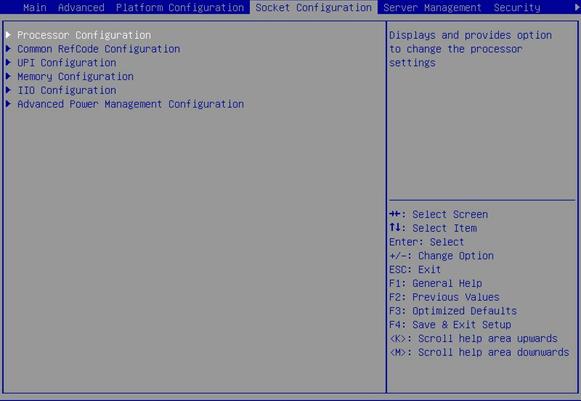
Table 95 Items on the Socket Configuration menu screen
|
Item |
Description |
|
Processor Configuration |
Submenu for configuring processors, as shown in Figure 142 and Figure 143. The submenu items are described in Table 98. |
|
Common RefCode Configuration |
Submenu for configuring the common reference code, as shown in Figure 146. The submenu items are described in Table 99. |
|
UPI Configuration |
Submenu for configuring Intel® UltraPath Interconnect (UPI) parameters, as shown in Figure 147. The submenu items are described in Table 100. |
|
Memory Configuration |
Submenu for configuring memory parameters, as shown in Figure 150. The submenu items are described in Table 102. |
|
IIO Configuration |
Submenu for configuring Integrated I/O module (IIO) parameters, as shown in Figure 154. The submenu items are described in Table 106. |
|
Advanced Power Management Configuration |
Submenu for configuring advanced power management parameters, as shown in Figure 161. The submenu items are described in Table 115. |
Processor Configuration submenu
Figure 142 and Figure 143 show the Processor Configuration submenu screen, on which you can configure features such as hyper-threading and hardware prefetcher for processors.
The submenu items are described in Table 96.
Figure 142 Processor Configuration submenu screen (1)

Figure 143 Processor Configuration submenu screen (2)
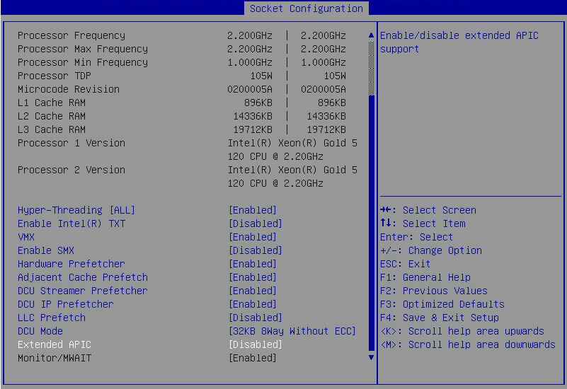
Table 96 Items on the Processor Configuration submenu screen
|
Item |
Description |
Default |
|
Per-Socket Configuration |
Access the submenu for per-socket configuration, as shown in Figure 144. The submenu items are described in Table 97. |
|
|
Processor BSP Revision |
Displays the processor revision. |
N/A |
|
Processor Socket |
Displays the sequence number of the processor socket. |
N/A |
|
Processor ID |
Displays the processor ID. |
N/A |
|
Processor Frequency |
Displays the processor frequency. |
N/A |
|
Processor Max Frequency |
Displays the maximum frequency allowed for each processor. |
N/A |
|
Processor Min Frequency |
Displays the minimum frequency allowed for each processor. |
N/A |
|
Processor TDP |
Displays the thermal design power (TDP) of the processor. |
N/A |
|
Microcode Revision |
Displays the microcode revision. |
N/A |
|
L1 Cache RAM |
Displays the capacity of the level-1 processor cache. |
N/A |
|
L2 Cache RAM |
Displays the capacity of the level-2 processor cache. |
N/A |
|
L3 Cache RAM |
Displays the capacity of the level-3 processor cache. |
N/A |
|
Processor 1 Version |
Displays the version of processor 1. |
N/A |
|
Processor 2 Version |
Displays the version of processor 2. |
N/A |
|
Hyper-Threading [ALL] |
This item is unavailable if the processer does not support hyper-threading. Select Enabled or Disabled to enable or disable hyper-threading for the processors. Hyper-threading allows a single processor to handle thread-level parallelism by enabling each physical processor core to function as two logical processor cores. This improves processor operating efficiency by enabling the processors to be compatible with multi-threaded OSs and software and reducing processor idle time. |
Enabled |
|
Select Enabled or Disabled to enable or disable Intel Trusted Execution Technology (TXT). Intel TXT provides comprehensive data security protection in a virtualized computing environment.
Set Debug Mode to Disabled before enabling Intel TXT. |
Disabled |
|
|
This item is configurable only when Enable Intel(R) TXT is set to Disabled. Select Enabled or Disabled to enable or disable CPU Virtual Machine Extensions (VMX). CPU VMX improves server hardware resource usage by enabling the virtualization layer or OS that supports VMX to use Intel hardware virtualization capabilities. For virtualization layers or OSs that do not support VMX, this feature does not take effect even if it is enabled. |
Enabled |
|
|
Enable SMX |
This item is configurable only when Enable Intel(R) TXT is set to Disable. Select Enabled or Disabled to enable or disable Intel Safer Mode Extensions (SMX). |
Disabled |
|
Hardware Prefetcher |
Select Enabled or Disabled to enable or disable hardware prefetcher. If hardware prefetcher is enabled, the processor prefetches instructions or data from memory to L2 cache before processing the instructions or data. This feature helps improve system performance by reducing memory access time and eliminating potential bottlenecks. |
Enabled |
|
Adjacent Cache Prefetch |
Select Enabled or Disabled to enable or disable adjacent cache prefetcher. Adjacent cache prefetcher is also referred to as mid-level cache (MLC) prefetcher. |
Enabled |
|
DCU Streamer Prefetcher |
Select Enabled or Disabled to enable or disable data cache unit (DCU) stream prefetcher. If the DCU stream prefetcher is enabled, the processor improves data processing and system performance by prefetching the stream and sending it to the L1 cache. |
Enabled |
|
DCU IP Prefetcher |
Select Enabled or Disabled to enable or disable DCU IP prefetcher. If the DCU IP prefetcher is enabled, the processor prefetches IP addresses to improve network connectivity and system performance. |
Enabled |
|
LLC Prefetch |
Select Enabled or Disabled to enable or disable the L3 or last level cache (LLC) prefetcher. |
Disabled |
|
DCU Mode |
Select a DCU mode. Options: · 32KB 8Way without ECC. · 16KB 4Way with ECC. |
32KB 8Way without ECC |
|
Extended APIC |
Select Enabled or Disabled to enable or disable the extended APIC mode. If the total number of processor cores exceeds 256, enable this mode as a best practice for the operating system to better support the processor multi-core feature. |
Disabled |
|
Monitor/MWAIT |
Select whether to enable MONITOR and MWAIT instructions. Options: · Auto. · Enabled. · Disabled. The MONITOR and MWAIT instructions allow the processors to optimize instruction execution. For some OSs, to disable CPU C State Control, you must disable this feature. Contact H3C Support if you have any further questions. |
Enabled |
Per-Socket Configuration submenu screen
Figure 144 shows the Per-Socket Configuration submenu screen. The submenu items are described in Table 97.
Figure 144 Per-Socket Configuration submenu screen

Table 97 Items on the Per-Socket Configuration submenu screen
|
Item |
Description |
|
CPU Socket N Configuration |
Submenu for configuring processor N, as shown in Figure 145. N represents the processor number. The screen displays only present processors. The submenu items are described in Table 98. |
CPU Socket Configuration submenu screen
Figure 145 shows the CPU Socket Configuration submenu screen. The submenu items are described in Table 98.
This section uses CPU socket 1 as an example.
Figure 145 CPU Socket 1 Configuration submenu screen
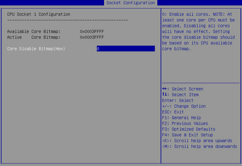
Table 98 Items on the CPU Socket 1 Configuration submenu screen
|
Description |
Default |
|
|
Available Core Bitmap |
Displays available core bitmaps. |
N/A |
|
Active Core Bitmap |
Displays active core bitmaps. |
N/A |
|
Core Disable Bitmap(Hex) |
Set the number of disabled core bitmaps for the processor in hexadecimal notation. To enable all cores of the processor, set the value to 0. Use the available core bitmaps as reference when you disable the cores of the processor. NOTE: Make sure a minimum of one core is enabled for a processor. If you disable all cores for a processor, the configuration does not take effect. |
0 |
Common RefCode Configuration submenu
Figure 146 shows the Common RefCode Configuration submenu screen, on which you can configure memory mapped I/O (MMIO) above 4 GB and non-uniform memory access (NUMA) settings as described in Table 99.
Figure 146 Common RefCode Configuration submenu screen

Table 99 Items on the Common RefCode Configuration submenu screen
|
Item |
Description |
Default |
|
MMIO High Base |
Select the address space for MMIO. Options: · 56T. · 40T. · 24T. · 16T. · 4T. · 1T. |
· R5300: 4T. · Other servers: 56T. |
|
MMIO High Granularity Size |
Select the address allocation size for MMIO. Options: · 1G. · 4G. · 16G. · 64G. · 256G. · 1024G. |
· R5300: 1024G. · Other servers: 64G. |
|
Isoc Mode |
Select whether to enable the Isoc mode. Options: · Enabled. · Disabled. · Auto. |
Auto |
|
NUMA |
Select Enabled or Disabled to enable or disable NUMA. Non-uniform memory access (NUMA) allows a processor to access its local memory faster than a non-local memory. |
Enabled |
UPI Configuration submenu
Figure 146 shows the UPI Configuration submenu screen, from which you can access the UPI General Configuration submenu to configure UPI parameters.
Figure 147 UPI Configuration submenu screen

UPI General Configuration submenu screen
Figure 148 shows the UPI General Configuration submenu screen, on which you can configure parameters such as the UPI link frequency as described in Table 100.
Figure 148 UPI General Configuration submenu screen

Table 100 Items on the UPI General Configuration submenu screen
|
Item |
Description |
Default |
|
Access the submenu that displays UPI information, as shown in Figure 149. The submenu items are described in Table 101. |
N/A |
|
|
Link Frequency Select |
Select a link frequency. Options: · 9.6 GT/s. · 10.4 GT/s. · Auto. |
Auto |
|
SNC |
The SNC feature can shorten the LLC and memory latency. Select whether to enable sub-NUMA clustering (SNC). Options: · Enabled. · Disabled. · Auto. |
Disabled |
|
XPT Prefetch |
Select whether to enable XPT prefetcher. Options: · Auto. · Enabled. · Disabled. |
Auto |
|
KTI Prefetch |
Select Enabled or Disabled to enable or disable KTI prefetcher. |
Enabled |
|
RdCur for XPT Prefetch |
Select whether to enable RdCur for XPT prefetcher. Options: · Auto—Enables the system to set RdCur for XPT prefetcher based on Si compatibility. · Enabled—Sets the suppress_mem_rd_prefetch_rdcur. · Disabled—Resets the RdCur for XPT prefetcher. |
Auto |
UPI Status submenu screen
Figure 149 shows the UPI Status submenu screen. The submenu items are described in Table 101.
Figure 149 UPI Status submenu screen
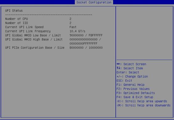
Table 101 Items on the UPI Status submenu screen
|
Item |
Description |
|
Number of CPU |
Displays the number of processors. |
|
Number of IIO |
Displays the number of integrated I/O modules. |
|
Current UPI Link Speed |
Displays the current speed of the UPI link. |
|
Current UPI Link Frequency |
Displays the current frequency of the UPI link. |
|
UPI Global MMIO Low Base / Limit |
Displays the UPI global MMIO low base address and limit. |
|
UPI Global MMIO High Base / Limit |
Displays the UPI global MMIO high base address and limit. |
|
UPI PCIe Configuration Base / Size |
Displays the PCIe configuration base address and size. |
Memory Configuration submenu
Figure 150 shows the Memory Configuration submenu screen, on which you can configure memory settings such as the memory speed and memory RAS features as described in Table 102.
Figure 150 Memory Configuration submenu screen
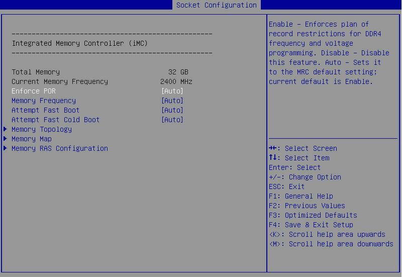
Table 102 Items on the Memory Configuration submenu screen
|
Item |
Description |
Default |
|
Total Memory |
Displays the total memory capacity. |
N/A |
|
Current Memory Frequency |
Displays the current memory frequency. |
N/A |
|
Enforce POR |
Select whether to enforce POR restrictions on DDR4 frequency selection to improve memory reliability. Options: · Auto. · Enabled. · Disabled. |
Auto |
|
Memory Frequency |
Select the maximum memory frequency, in MHz. Options: · Auto. · 1600. · 1866. · 2133. · 2400. · 2666. · 2933. This option is available only for Cascade Lake processors. The value range is 1866 to 2666 when Intel DCPMMs are used. |
Auto |
|
Attempt Fast Boot |
Select whether to enable fast boot attempt. Options: · Auto—Enables fast boot by default. · Enabled—Enables fast boot. If skipping part of memory reference code (MRC) can speed up the warm boot process, the system skips this part of MRC. · Disabled—Disables fast boot. |
· R8900: Disabled. · Other servers: Auto. |
|
Attempt Fast Cold Boot |
Select whether to enable fast cold boot attempt. Options: · Auto—Enables fast cold boot by default. · Enabled—Enables fast cold boot. If skipping part of MRC can speed up the cold boot process, the system skips this part of MRC. · Disabled—Disables fast cold boot. |
· R8900: Disabled. · Other servers: Auto. |
|
Memory Topology |
Access the submenu that displays memory information, as shown in Figure 151. The submenu items are described in Table 103. |
N/A |
|
Memory Map |
Access the submenu for configuring memory mapping and interleaving, as shown in Figure 152. You can enable memory interleaving to improve memory read and write performance. The submenu items are described in Table 104. |
N/A |
|
Access the submenu for configuring memory reliability, availability, and serviceability (RAS) settings, as shown in Figure 153. The submenu items are described in Table 105. |
N/A |
Memory Topology submenu screen
Figure 151 shows the Memory Topology submenu screen. The submenu items are described in Table 103.
Figure 151 Memory Topology submenu screen
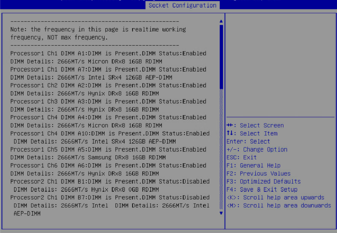
Table 103 Items on the Memory Topology submenu screen
|
Item |
Description |
|
Processor 1 Ch1 DIMM A1:DIMM is Present.DIMM Status:Enabled.DIMM Details:2666MT/s Micron DRx8 16GB RDIMM |
Displays information about the memory module of a processor (for example, DIMM A1 in channel 1 of processor 1), including: · Presence of the DIMM. · Enabling status of the DIMM. · Memory specifications: ¡ Memory frequency. ¡ Vendor. ¡ Number of ranks and bit width. ¡ Memory capacity. ¡ Memory type. |
Memory Map submenu screen
Figure 152 shows the Memory Map submenu screen. The submenu items are described in Table 104.
Figure 152 Memory Map submenu screen
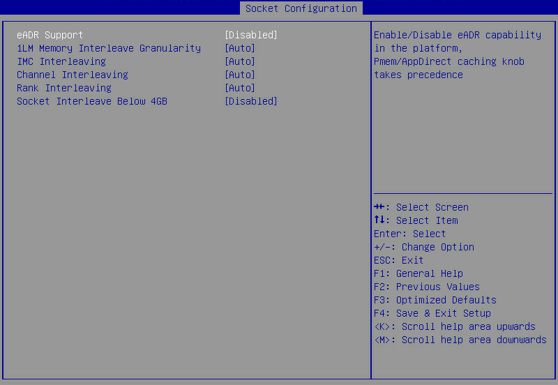
Table 104 Items on the Memory Map submenu screen
|
Item |
Description |
Default |
|
eADR Support |
Select Enabled or Disabled to enable or disable support for eADR. |
Disabled |
|
1LM Memory Interleave Granularity |
Select the granularity for 1LM memory interleaving. Options: · 256B Target,256B Channel. · 64B Target,64B Channel. |
Auto |
|
IMC Interleaving |
This item is configurable only when NUMA is disabled. For more information about NUMA, see"Common RefCode Configuration submenu." Select an interleaving mode for integrated memory controllers. Options: · Auto. · 1-way Interleave. · 2-way Interleave. |
Auto |
|
Channel Interleaving |
Select a memory channel interleaving mode. Options: · Auto. · 1-way Interleave. · 2-way Interleave. · 3-way Interleave. High-level interleaving improves memory performance, but low-level interleaving reduces power consumption. |
Auto |
|
Rank Interleaving |
Select a memory rank interleaving mode. Rank interleaving enables interleaving of memory ranks on the same channel. Options: · Auto. · 1-way Interleave. · 2-way Interleave. · 4-way Interleave. · 8-way Interleave. |
Auto |
|
Socket Interleave Below 4GB |
Select Enabled or Disabled to enable or disable socket interleaving for memory below 4 GB. |
Disabled |
Memory RAS Configuration submenu screen
Figure 153 shows the Memory RAS Configuration submenu screen. The submenu items are described in Table 105.
Figure 153 Memory RAS Configuration submenu screen
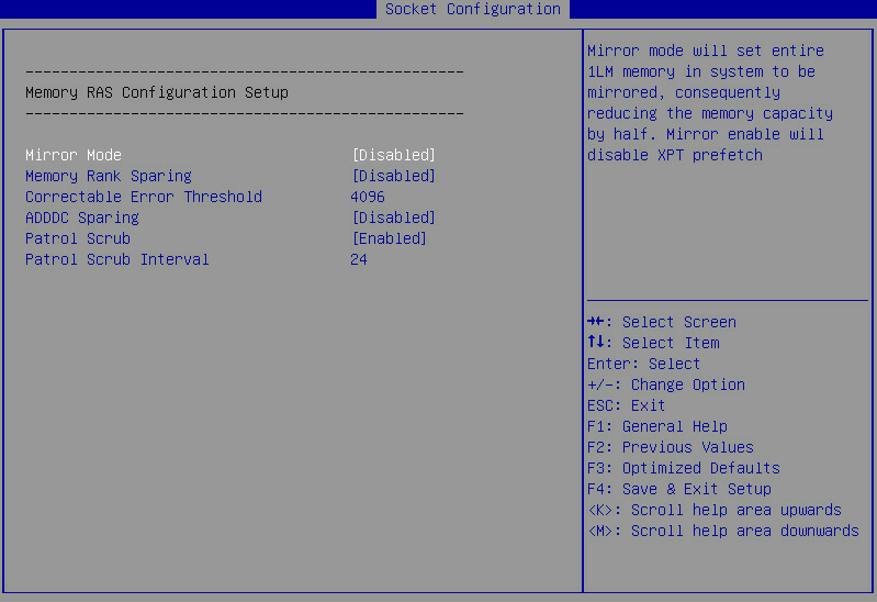
Table 105 Items on the Memory RAS Configuration submenu screen
|
Item |
Description |
Default |
|
Mirror Mode |
Select a memory mirroring mode to optimize system reliability by using half the system memory capacity for backup. Options: · Disabled. After you enable memory mirroring, the Total Memory Size item on the Memory Configuration submenu screen displays the total available memory, which is half the installed physical memory. To identify the installed physical memory capacity, access the Smbios Type 17 structure from a shell (for example, the CLI) of the operating system. If all the DIMM slots are installed with DIMMs and memory mirroring is enabled, the memory capacity displayed on the POST self-test screen and the BIOS setup utility is larger than half the total installed physical memory. |
Disabled |
|
Memory Rank Sparing |
Select Enabled or Disabled to enable or disable memory sparing for memory ranks. Memory rank sparing uses some ranks in the memory as spare ranks for the non-spare ranks on the same channel. Memory rank sparing is mutually exclusive with memory mirroring. When the independent RAS mode is set and memory rank sparing is enabled, both the independent RAS mode and memory rank sparing take effect. |
Disabled |
|
Multi Rank Sparing |
Select the number of spare ranks per channel. This item is available only when Memory Rank Sparing is set to Enabled. Options: · One Rank—Uses one spare rank on a channel. To use one spare rank, each channel must have a minimum of two ranks. · Two Rank—Uses two spare ranks on a channel. To use two spare ranks, each channel must have a minimum of four ranks. |
Two Rank |
|
Set the correctable error threshold in decimal notation. Value range: 0 to 32767. Value 0 indicates that no correctable error threshold is set. |
· R8900: 1000 · Other servers: 4096 |
|
|
Leaky bucket low bit |
This item is configurable only when Memory Rank Sparing is set to Enabled. Set the leaky bucket low bit in the range of 0 to 3F in hexadecimal notation. |
10 |
|
Leaky bucket high bit |
This item is configurable only when Memory Rank Sparing is set to Enabled. Set the leaky bucket high bit in the range of 0 to 29 in hexadecimal notation. |
11 |
|
ADDDC Sparing |
Select Enabled or Disabled to enable or disable adaptive double device data correction sparing (ADDDC). ADDDC sparing can correct two-bit memory errors. |
· R8900: Enabled · Other servers: Disabled |
|
Enable ADDDC Error Injection |
This item is available only when ADDDC Sparing is set to Enabled. Select Enabled or Disabled to enable or disable ADDDC error injection. |
Enabled |
|
Select Enabled or Disabled to enable or disable patrol scrubbing. Patrol scrubbing allows a processor to automatically search for and correct correctable memory errors at regular intervals while the system is idle. |
Enabled |
|
|
Patrol Scrub Interval |
Set the patrol scrub interval in hours. This item is available only when Patrol Scrub is set to Enabled. |
24 |
IIO Configuration menu
Figure 154 and Figure 155 show the IIO Configuration submenu screens, on which you can configure the peripheral component interconnect express (PCIe) slots, including their link speed and maximum payload size, as described in Table 106.
Figure 154 IIO Configuration submenu screen (1)
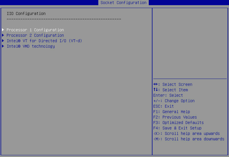
Figure 155 IIO Configuration submenu screen (2)
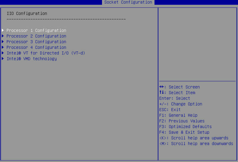
Table 106 Items on the IIO Configuration submenu screen
|
Item |
Description |
|
Processor n Configuration |
This item is available only when a processor is in position. Access the IIO configuration submenu for a processor, for example, processor 1 or processor 2. The port items on the Processor 1 Configuration submenu vary by server model and PCIe module. Figure 156 uses the Processor 1 Configuration submenu screen as an example. The submenu items are described in Table 107. |
|
Intel® VT for Directed I/O (VT-d) |
Access the submenu for enabling or disabling Intel virtualization technology for directed I/O (VT-d), as shown in Figure 158. The submenu items are described in Table 109. |
|
Intel® VMD technology |
Access the submenu for configuring Intel Volume Management Device (VMD) technology, as shown in Figure 159. The submenu items are described in Table 110. |
Processor 1 Configuration submenu screen
Figure 156 shows the Processor 1 Configuration submenu screen. The submenu items are described in Table 107.
Figure 156 Processor 1 Configuration submenu screen
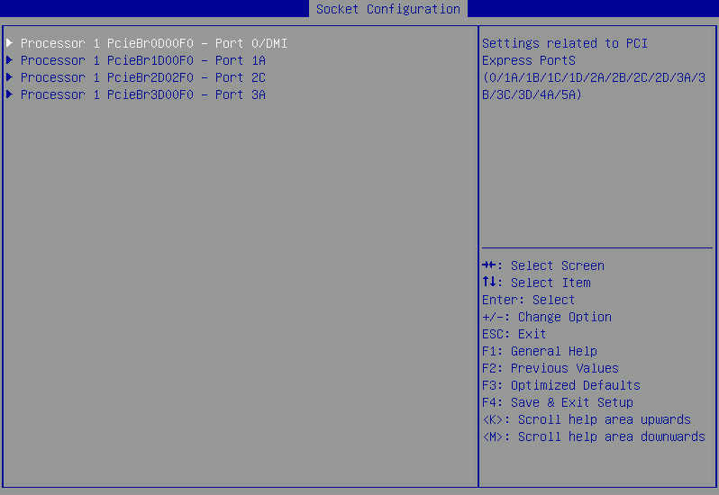
Table 107 Items on the Processor n Configuration submenu screen
|
Item |
Description |
|
PCIe port submenu items, for example: Processor 1 PcieBr0D00F0 - Port 0/DMI Processor 1 PcieBr1D00F0 - Port 1A Processor 1 PcieBr2D02F0 - Port 2C Processor 1 PcieBr3D00F0 - Port 3A |
Submenus for configuring PCIe ports. Figure 157 shows the submenu for configuring Processor 1 PcieBr1D00F0 - Port 1A, which slightly differs from the submenu for other PCIe ports. The submenu items are described in Table 108. |
Figure 157 Submenu screen for Processor 1 PcieBr1D00F0 - Port 1A
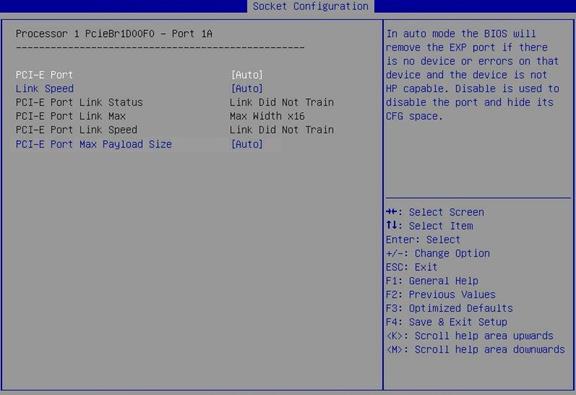
Table 108 Items on the Processor 1 PcieBr1D00F0 - Port 1A submenu screen
|
Item |
Description |
Default |
|
PCI-E Port |
This item is available only for non-DMI PCIe ports. Select whether to enable the PCIe port. Options: · Auto. · Enabled. · Disabled. |
Auto |
|
Link Speed |
Select a link speed for the PCIe port. Options: · Auto. · Gen 1 (2.5 GT/s). · Gen 2 (5.0 GT/s). · Gen 3 (8.0 GT/s). |
Auto |
|
PCI-E Port Link Status |
Displays the PCIe port link status. |
N/A |
|
PCI-E Port Link Max |
Displays the maximum bandwidth of the PCIe port link. |
N/A |
|
PCI-E Port Link Speed |
Displays the PCIe port link speed. |
N/A |
|
PCI-E Port Max Payload Size |
Set the maximum payload size of the PCIe port. Options: · Auto—Sets the maximum payload size to 256B by default. · 128B—Sets the maximum payload size to 128B. The configuration might affect the performance of NVMe drives. You can set the maximum payload size of a PCIe port to 128B if NVMe drive hot swapping causes the system to reboot. · 256B—Sets the maximum payload size to 256B. |
256B |
Intel® VT for Directed I/O (VT-d) submenu screen
Figure 158 shows the Intel® VT for Directed I/O (VT-d) submenu screen. The submenu items are described in Table 109.
Figure 158 Intel® VT for Directed I/O (VT-d) submenu screen
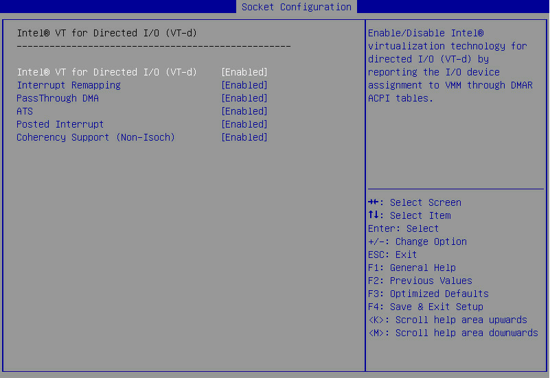
Table 109 Items on the Intel® VT for Directed I/O (VT-d) submenu screen
|
Item |
Description |
Default |
|
Select Enabled or Disabled to enable or disable Intel virtualization technology for directed I/O (VT-d). With this feature enabled, management programs and OSs that support this feature can provide directed I/O with hardware support offered by the Intel virtualization technology. You can enable this feature even if such management programs and OSs are not used. Intel VT-d enhances system security and reliability, and improves the performance of I/O devices in a virtualized environment. NOTE: As a best practice, enable this feature for the R8900. |
Enabled |
|
|
Interrupt Remapping |
Select Enabled or Disabled to enable or disable interrupt remapping. NOTE: As a best practice, enable this feature for the R8900. |
Enabled |
|
PassThrough DMA |
Select Enabled or Disabled to enable or disable pass-through direct memory access (DMA). |
Enabled |
|
ATS |
Select Enabled or Disabled to enable or disable non-Isoch VT-d engine address translation services (ATS). |
Enabled |
|
Posted Interrupt |
Select Enabled or Disabled to enable or disable the posted interrupt feature. |
Enabled |
|
Coherency Support(Non-Isoch) |
Select Enabled or Disabled to enable or disable support for non-Isoch coherency. |
Enabled |
Intel® VMD technology submenu screen
Figure 159 shows the Intel® VMD technology submenu screen. The submenu items are described in Table 110.
Figure 159 Intel® VMD technology submenu screen
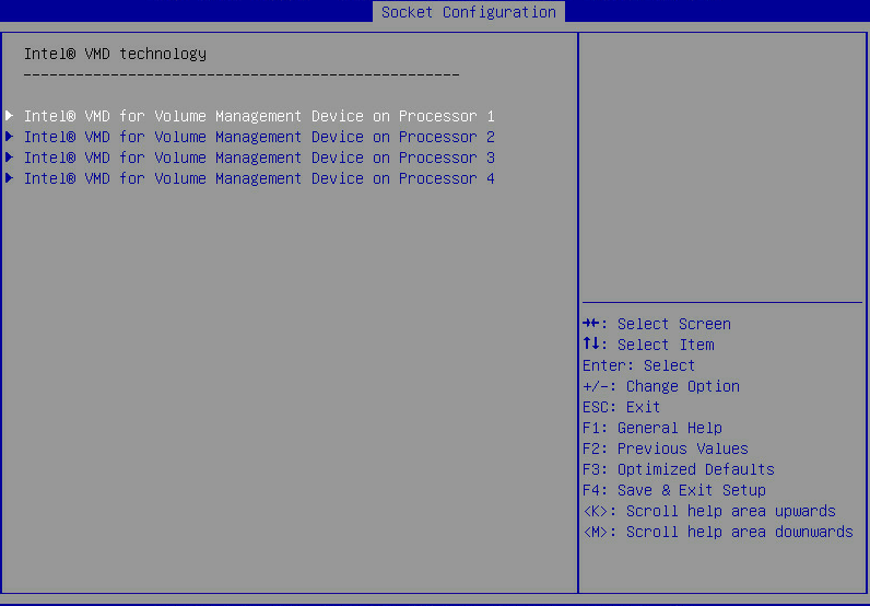
Table 110 Items on the Intel® VMD technology submenu screen
|
Item |
Description |
|
Intel® VMD for Volume Management Device on Processor n |
This item is available only when a processor is in position. VMD configuration submenu for the volume management device on a processor. Figure 160 shows the submenu for the volume management device on Processor 1 as an example, which is the same with the submenu for other processors. The submenu items are described in Table 111. |
Figure 160 Intel® VMD for Volume Management Device on Processor 1 submenu screen
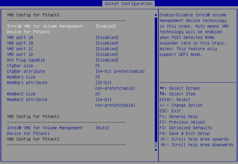
Table 111 Items on the Intel® VMD for Volume Management Device on Processor 1 submenu screen
|
Item |
Description |
Default |
|
Intel® VMD for Volume Management Device for PStack0 |
This item is available only in UEFI boot mode. Select whether to enable Intel® VMD for the volume management device in PStack0. Options: · Disabled—Disables Intel® VMD for the volume management device for PStack0. · Enabled—Enables Intel® VMD the volume management device for PStack0. The screen displays items for further configuration if you set the item to Enabled. · Auto—Enables Intel® VMD automatically when a device is detected for the stack during POST. |
Auto |
|
VMD port 1A |
This item is available only when Intel® VMD for Volume Management Device for the corresponding PStack is enabled. Select Enabled or Disabled to enable or disable VMD port 1A. |
Disabled |
|
VMD port 1B |
This item is available only when Intel® VMD for Volume Management Device for the corresponding PStack is enabled. Select Enabled or Disabled to enable or disable VMD port 1B. |
Disabled |
|
VMD port 1C |
This item is available only when Intel® VMD for Volume Management Device for the corresponding PStack is enabled. Select Enabled or Disabled to enable or disable VMD port 1C. |
Disabled |
|
VMD port 1D |
This item is available only when Intel® VMD for Volume Management Device for the corresponding PStack is enabled. Select Enabled or Disabled to enable or disable VMD port 1D. |
Disabled |
|
Hot Plug Capable |
This item is available only when Intel® VMD for Volume Management Device for the corresponding PStack is enabled. Select Enabled or Disabled to enable or disable hot swapping on the PCIe root port. |
Disabled |
|
CfgBar Size |
This item is available only when Intel® VMD for Volume Management Device for the corresponding PStack is enabled. Set the base address register (BAR) size in bits. Value range: 20 to 27. |
25 |
|
CfgBar attribute |
This item is available only when Intel® VMD for Volume Management Device for the corresponding PStack is enabled. Set the BAR attribute. |
64-bit prefetchable |
|
MemBar1 size |
This item is available only when Intel® VMD for Volume Management Device for the corresponding PStack is enabled. Set the size of memory bar 1. The minimum size is 20 bits. |
25 bits |
|
MemBar1 attribute |
This item is available only when Intel® VMD for Volume Management Device for the corresponding PStack is enabled. Set the attribute of memory bar 1. Options: · 32-bit non-prefetchable. · 64-bit non-prefetchable. · 64-bit prefetchable. |
32-bit non-prefetchable |
|
MemBar2 size |
This item is available only when Intel® VMD for Volume Management Device for the corresponding PStack is enabled. Set the size of memory bar 2. The minimum size is 20 bits. |
25 bits |
|
MemBar2 attribute |
This item is available only when Intel® VMD for Volume Management Device for the corresponding PStack is enabled. Set the attribute of memory bar 2. Options: · 64-bit non-prefetchable. · 64-bit prefetchable. · 32-bit non-prefetchable—This option is available only for Intel® VMD for the volume management device for PStack0 on processor 1. |
64-bit non-prefetchable |
|
Intel® VMD for Volume Management Device for PStack1 |
This item is available only in UEFI boot mode. Select whether to enable Intel® VMD for the volume management device for PStack1. Options: · Disabled—Disables Intel® VMD for the volume management device for PStack1. · Enabled—Enables Intel® VMD the volume management device for PStack1. The screen displays items for further configuration if you set this item to Enabled. · Auto—Enables Intel® VMD automatically when a device is detected for the stack during POST. |
Auto |
|
Intel® VMD for Volume Management Device for PStack2 |
This item is available only in UEFI boot mode. Select whether to enable Intel® VMD for the volume management device for PStack2. Options: · Disabled—Disables Intel® VMD for the volume management device for PStack2. · Enabled—Enables Intel® VMD the volume management device for PStack2. The screen displays items for further configuration if you set this item to Enabled. · Auto—Enables Intel® VMD automatically when a device is detected for the stack during POST. |
Auto |
Mapping relations between VMD items and NVMe device slots
|
|
IMPORTANT: VMD items unmentioned in the following tables of this section support standard PCIe rather than VMD. To avoid device identification failure on PCIe slots, do not change the configuration of these VMD items. |
For the E3200, R4300, R5300, and R8900, you can determine the corresponding VMD items for the logic slot of each NVMe device, as shown in Table 112.
|
Logic slot of NVMe device |
VMD items |
||
|
R4300 |
|||
|
Slot 100 |
Intel® VMD for Volume Management Device on Processor 2 |
Intel® VMD for Volume Management Device for PStack0 |
VMD port 1C |
|
Slot 101 |
Intel® VMD for Volume Management Device on Processor 2 |
Intel® VMD for Volume Management Device for PStack0 |
VMD port 1D |
|
Slot 102 |
Intel® VMD for Volume Management Device on Processor 2 |
Intel® VMD for Volume Management Device for PStack2 |
VMD port 3A |
|
Slot 103 |
Intel® VMD for Volume Management Device on Processor 2 |
Intel® VMD for Volume Management Device for PStack2 |
VMD port 3B |
|
Slot 104 |
Intel® VMD for Volume Management Device on Processor 2 |
Intel® VMD for Volume Management Device for PStack2 |
VMD port 3C |
|
Slot 105 |
Intel® VMD for Volume Management Device on Processor 2 |
Intel® VMD for Volume Management Device for PStack2 |
VMD port 3D |
|
R5300 (12LFF) |
|||
|
Slot 200 |
Intel® VMD for Volume Management Device on Processor 2 |
Intel® VMD for Volume Management Device for PStack2 |
VMD port 3A |
|
Slot 201 |
Intel® VMD for Volume Management Device on Processor 2 |
Intel® VMD for Volume Management Device for PStack2 |
VMD port 3B |
|
Slot 202 |
Intel® VMD for Volume Management Device on Processor 2 |
Intel® VMD for Volume Management Device for PStack2 |
VMD port 3C |
|
Slot 203 |
Intel® VMD for Volume Management Device on Processor 2 |
Intel® VMD for Volume Management Device for PStack2 |
VMD port 3D |
|
R5300 (24LFF) |
|||
|
Slot 200 |
Intel® VMD for Volume Management Device on Processor 1 |
Intel® VMD for Volume Management Device for PStack2 |
VMD port 3A |
|
Slot 201 |
Intel® VMD for Volume Management Device on Processor 1 |
Intel® VMD for Volume Management Device for PStack2 |
VMD port 3B |
|
Slot 202 |
Intel® VMD for Volume Management Device on Processor 1 |
Intel® VMD for Volume Management Device for PStack2 |
VMD port 3C |
|
Slot 203 |
Intel® VMD for Volume Management Device on Processor 1 |
Intel® VMD for Volume Management Device for PStack2 |
VMD port 3D |
|
Slot 204 |
Intel® VMD for Volume Management Device on Processor 2 |
Intel® VMD for Volume Management Device for PStack2 |
VMD port 3A |
|
Slot 205 |
Intel® VMD for Volume Management Device on Processor 2 |
Intel® VMD for Volume Management Device for PStack2 |
VMD port 3B |
|
Slot 206 |
Intel® VMD for Volume Management Device on Processor 2 |
Intel® VMD for Volume Management Device for PStack2 |
VMD port 3C |
|
Slot 207 |
Intel® VMD for Volume Management Device on Processor 2 |
Intel® VMD for Volume Management Device for PStack2 |
VMD port 3D |
|
R8900 |
|||
|
Slots 210 through 213 |
Intel® VMD for Volume Management Device on Processor 2 |
Intel® VMD for Volume Management Device for Pstack1 |
VMD ports 2A, 2B, 2C, and 2D |
|
Slots 214 through 217 |
Intel® VMD for Volume Management Device on Processor 1 |
Intel® VMD for Volume Management Device for Pstack1 |
VMD ports 2A, 2B, 2C, and 2D |
|
Slots 220 through 223 |
Intel® VMD for Volume Management Device on Processor 4 |
Intel® VMD for Volume Management Device for Pstack1 |
VMD ports 2A, 2B, 2C, and 2D |
|
Slots 224 through 227 |
Intel® VMD for Volume Management Device on Processor 3 |
Intel® VMD for Volume Management Device for Pstack1 |
VMD ports 2A, 2B, 2C, and 2D |
|
Slots 230 through 233 |
Intel® VMD for Volume Management Device on Processor 6 |
Intel® VMD for Volume Management Device for Pstack1 |
VMD ports 2A, 2B, 2C, and 2D |
|
Slots 234 through 237 |
Intel® VMD for Volume Management Device on Processor 5 |
Intel® VMD for Volume Management Device for Pstack1 |
VMD ports 2A, 2B, 2C, and 2D |
|
Slots 240 through 243 |
Intel® VMD for Volume Management Device on Processor 8 |
Intel® VMD for Volume Management Device for Pstack1 |
VMD ports 2A, 2B, 2C, and 2D |
|
Slots 244 through 247 |
Intel® VMD for Volume Management Device on Processor 7 |
Intel® VMD for Volume Management Device for Pstack1 |
VMD ports 2A, 2B, 2C, and 2D |
|
E3200 |
|||
|
Slots 111 through 114 |
Intel® VMD for Volume Management Device on Processor 1 |
Intel® VMD for Volume Management Device for Pstack1 |
VMD ports 2A, 2B, 2C, and 2D |
|
Slots 115 through 118 |
Intel® VMD for Volume Management Device on Processor 2 |
Intel® VMD for Volume Management Device for Pstack2 |
VMD ports 3A, 3B, 3C, and 3D |
|
Slots 121 through 124 |
Intel® VMD for Volume Management Device on Processor 1 |
Intel® VMD for Volume Management Device for PStack2 |
VMD ports 3A, 3B, 3C, and 3D |
|
Slots 125 through 128 |
Intel® VMD for Volume Management Device on Processor 2 |
Intel® VMD for Volume Management Device for PStack0 |
VMD ports 1A, 1B, 1C, and 1D |
|
Slots 141 through 144 |
Intel® VMD for Volume Management Device on Processor 1 |
Intel® VMD for Volume Management Device for PStack0 |
VMD ports 1A, 1B, 1C, and 1D |
|
Slots 151 through 154 |
Intel® VMD for Volume Management Device on Processor 2 |
Intel® VMD for Volume Management Device for PStack1 |
VMD ports 2A, 2B, 2C, and 2D |
For the B5700, B5800, and B7800, you can determine the corresponding VMD items for the physical slot of each NVMe SSD, as shown in Table 113.
Table 113 Mapping relations slots between NVMe SSD slots and VMD items (for the B5700, B5800, and B7800)
|
NVMe SSD |
VMD items |
||
|
B5700 |
|||
|
NVMe SSD 1 |
Intel® VMD for Volume Management Device on Processor 1 |
Intel® VMD for Volume Management Device for PStack1 |
VMD port 2A |
|
NVMe SSD 2 |
Intel® VMD for Volume Management Device on Processor 2 |
Intel® VMD for Volume Management Device for PStack0 |
VMD port 1A |
|
B5800 |
|||
|
NVMe SSD 6 |
Intel® VMD for Volume Management Device on Processor 1 |
Intel® VMD for Volume Management Device for PStack0 |
VMD port 1A |
|
NVMe SSDs 7 through 10 |
Intel® VMD for Volume Management Device on Processor 2 |
Intel® VMD for Volume Management Device for PStack0 |
VMD ports 1A, 1B, 1C, and 1D |
|
NVMe SSDs 11 through 14 |
Intel® VMD for Volume Management Device on Processor 2 |
Intel® VMD for Volume Management Device for PStack2 |
VMD ports 3A, 3B, 3C, and 3D |
|
B7800 |
|||
|
NVMe SSD 1 |
Intel® VMD for Volume Management Device on Processor 2 |
Intel® VMD for Volume Management Device for PStack0 |
VMD port 1C |
|
NVMe SSD 2 |
Intel® VMD for Volume Management Device on Processor 2 |
Intel® VMD for Volume Management Device for PStack0 |
VMD port 1D |
|
NVMe SSD 3 |
Intel® VMD for Volume Management Device on Processor 3 |
Intel® VMD for Volume Management Device for PStack1 |
VMD port 2C |
|
NVMe SSD 4 |
Intel® VMD for Volume Management Device on Processor 3 |
Intel® VMD for Volume Management Device for PStack1 |
VMD port 2D |
For the B5700, B7800, R2700, R2900, R4700, R4900, R6700, and R6900, you can determine the corresponding VMD items for each PCIe riser connector if NVMe devices are installed through riser cards, as shown in Table 114.
Table 114 Mapping relations between PCIe riser connectors and VMD items (for the B5700, B7800, R2700, R2900, R4700, R4900, R6700, and R6900)
|
PCIe riser connector |
VMD items |
||
|
B5700 |
|||
|
PCIe riser connector 1 |
Intel® VMD for Volume Management Device on Processor 2 |
Intel® VMD for Volume Management Device for PStack2 |
VMD ports 3A, 3B, 3C, and 3D |
|
B7800 |
|||
|
PCIe riser connector 1 |
Intel® VMD for Volume Management Device on Processor 2 |
Intel® VMD for Volume Management Device for PStack2 |
VMD ports 3A, 3B, 3C, and 3D |
|
PCIe riser connector 2 |
Intel® VMD for Volume Management Device on Processor 3 |
Intel® VMD for Volume Management Device for PStack2 |
VMD ports 3A, 3B, 3C, and 3D |
|
R2900 and R4900 |
|||
|
PCIe riser connector 1 |
Intel® VMD for Volume Management Device on Processor 1 |
Intel® VMD for Volume Management Device for PStack0 |
VMD port 1A, 1B, 1C, 1D |
|
Intel® VMD for Volume Management Device for Pstack2 |
VMD port 3A, 3B, 3C, 3D |
||
|
PCIe riser connector 2 |
Intel® VMD for Volume Management Device on Processor 2 |
Intel® VMD for Volume Management Device for PStack1 |
VMD port 2A, 2B, 2C, 2D |
|
R2700 and R4700 |
|||
|
PCIe riser connector 1 |
Intel® VMD for Volume Management Device on Processor 1 |
Intel® VMD for Volume Management Device for PStack0 |
VMD port 1A, 1B, 1C, 1D |
|
PCIe riser connector 2 |
Intel® VMD for Volume Management Device on Processor 1 |
Intel® VMD for Volume Management Device for PStack0 |
VMD port 2A, 2B, 2C, 2D |
|
R6700 |
|||
|
PCIe riser connector 1 |
Intel® VMD for Volume Management Device on Processor 1 |
Intel® VMD for Volume Management Device for PStack0 |
VMD ports 1A, 1B, 1C, and 1D |
|
Intel® VMD for Volume Management Device for PStack2 |
VMD ports 3A, 3B, 3C, and 3D (Required if the riser card on the connector can hold eight NVMe drives) |
||
|
PCIe riser connector 2 |
Intel® VMD for Volume Management Device on Processor 2 |
Intel® VMD for Volume Management Device for PStack0 |
VMD ports 1A, 1B, 1C, and 1D |
|
Intel® VMD for Volume Management Device for PStack1 |
VMD ports 2A, 2B, 2C, and 2D (Required if the riser card on the connector can hold eight NVMe drives) |
||
|
R6900 |
|||
|
Compute module 1 PCIe riser connector 0 |
Intel® VMD for Volume Management Device on Processor 2 |
Intel® VMD for Volume Management Device for PStack1 |
VMD port 2A, 2B, 2C, 2D |
|
Compute module 2 PCIe riser connector 0 |
Intel® VMD for Volume Management Device on Processor 4 |
Intel® VMD for Volume Management Device for PStack1 |
VMD port 2A, 2B, 2C, 2D |
Advanced Power Management Configuration submenu
Figure 161 shows the Advanced Power Management Configuration submenu screen, on which you can configure advanced power management parameters, including P state control and C state control for processors and power management policy.
The submenu items are described in Table 115.
Figure 161 Advanced Power Management Configuration submenu screen
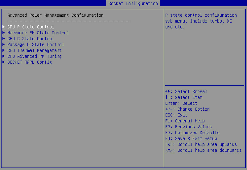
Table 115 Items on the Advanced Power Management Configuration submenu screen
|
Item |
Description |
|
CPU P State Control |
Submenu for configuring CPU P-state control options, as shown in Figure 162. On the submenu, you can select whether to enable Enhanced Intel SpeedStep Technology (EIST) and turbo mode as described in Table 116. |
|
Hardware PM State Control |
Submenu for configuring hardware P-state control options, as shown in Figure 163. The submenu items are described in Table 117. |
|
CPU C State Control |
Submenu for configuring CPU C-state control options, as shown in Figure 164. On the submenu, you can control the power consumption of CPUs in idle state as described in Table 118. |
|
Package C State Control |
Submenu for configuring package C state control options, as shown in Figure 165. On the submenu, you can set the C2 to C3 state transition timer as described in Table 119. |
|
CPU Thermal Management |
Submenu for configuring CPU thermal management options, as shown in Figure 166. The submenu items are described in Table 120. |
|
CPU Advanced PM Tuning |
Submenu for configuring CPU advanced power management tuning, as shown in Figure 168. The submenu items are described in Table 122. |
|
SOCKET RAPL Config |
Submenu for configuring socket RAPL settings, as shown in Figure 170. The submenu items are described in Table 124. |
CPU P State Control submenu screen
Figure 162 shows the CPU P State Control submenu screen. The submenu items are described in Table 116.
Figure 162 CPU P State Control submenu screen
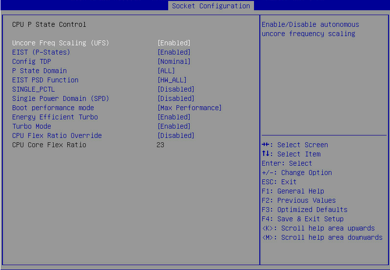
Table 116 Items on the CPU P State Control submenu screen
|
Description |
Default |
|
|
Uncore Freq Scaling (UFS) |
Select Enabled or Disabled to enable or disable uncore frequency scaling (UFS). |
Enabled |
|
EIST (P-States) |
Select Enabled or Disabled to enable or disable Enhanced Intel SpeedStep Technology (EIST). EIST allows the system to automatically adjust processor voltage and core frequency to reduce power consumption and heat dissipation. |
Enabled |
|
Config TDP |
This item is available only when EIST (P-States) is set to Enabled. Set the level of the thermal design power (TDP) that represents the maximum amount of power required for system cooling. Options: · Nominal. · Level1. · Level2. |
Nominal |
|
P State Domain |
Set the P-states domain. Options: · ALL. · ONE. |
ALL |
|
EIST PSD Function |
Set the method for EIST to automatically adjust processor voltage and core frequency to reduce power consumption and help heat dissipation. Options: · HW_ALL—Specifies all the hardware. · SW_ALL—Specifies all the software. · SW_ANY—Specifies any software. |
HW_ALL |
|
SINGLE_PCTL |
Select Enabled or Disabled to enable or disable the SINGLE_PCTL mode. |
Disabled |
|
Single Power Domain (SPD) |
Select Enabled or Disabled to enable or disable single power domain (SPD) configuration. |
Disable |
|
Boot performance mode |
Set the boot performance state for BIOS before the OS takes over. Options: · Max Performance. · Max Efficient. · Set by Intel Node Manager. |
Max Performance |
|
Energy Efficient Turbo |
Select Enabled or Disabled to enable or disable energy efficient Turbo mode. |
Enabled |
|
Turbo Mode |
Select Enabled or Disabled to enable or disable the Turbo mode. |
Enabled |
|
CPU Flex Ratio Override |
Select Enabled or Disabled to enable or disable setting processor flex ratio. |
Disabled |
|
CPU Core Flex Ratio |
This item is configurable only when CPU Flex Ratio Override is set to Enabled. Set the the processor core ratio multiplier. The value range is 0 to 100. |
23 |
Hardware PM State Control submenu screen
Figure 163 shows the Hardware PM State Control submenu screen. The submenu items are described in Table 117.
Figure 163 Hardware PM State Control submenu screen
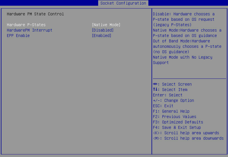
Table 117 Items on the Hardware PM State Control submenu screen
|
Item |
Description |
Default |
|
Hardware P-States |
Set the mode for selecting the hardware P-states. Options: · Disabled—Enables the hardware to select a P-state based on operating system request. · Native Mode—Allows the hardware to select a P-state with the guidance of the operating system. · Out of Band Mode—Allows the hardware to autonomously select a P-state without guidance of the operating system. · Native Mode with No Legacy Support—Selects the Native mode with no support for Legacy. |
Native Mode |
|
HardwarePM Interrupt |
This item is configurable only when Hardware P-States is set to Native Mode. Select Enabled or Disabled to enable or disable hardware PM interrupt. |
Disabled |
|
EPP Enable |
This item is unconfigurable when Hardware P-States is set to Disabled. Select Enabled or Disabled to enable or disable ENERGY_PERFORMANCE_PREFERENCE (EPP). If this feature is disabled, the system uses ENEGY_PERF_BIAS (EPB). |
Enabled |
|
EPP profile |
This item is unconfigurable when Hardware P-States is set to Disabled. Set the EPP mode. Options: · Performance—Provides maximum system performance at the expense of energy efficiency. · Balanced Performance—Provides optimum performance with good energy efficiency. · Balanced Power—Provides optimum power efficiency with good performance. · Power—Provides maximum power efficiency (maximum power saving) at the expense of system performance. |
Balanced Performance |
CPU C State Control submenu screen
Figure 164 shows the CPU C State Control submenu screen. The submenu items are described in Table 118.
Figure 164 CPU C State Control submenu screen
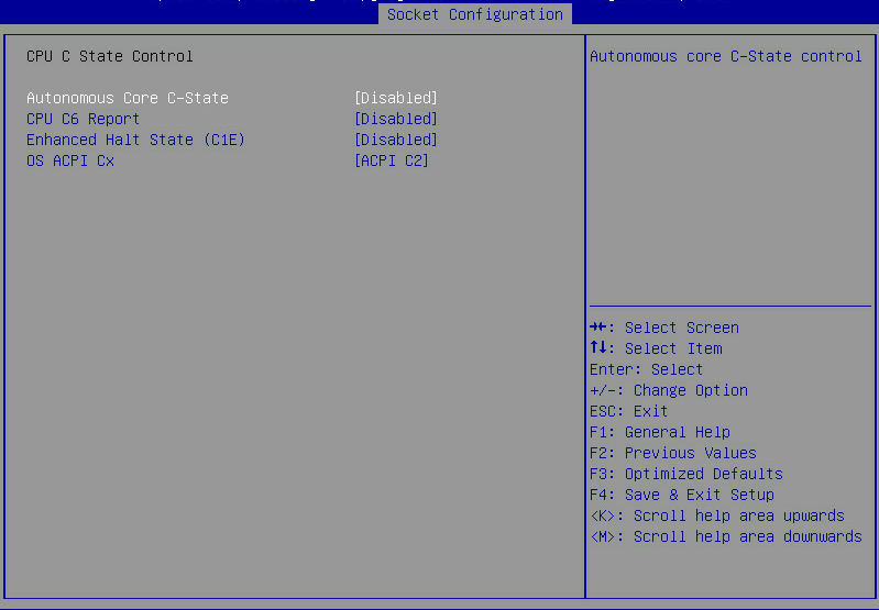
Table 118 Items on the CPU C State Control submenu screen
|
Description |
Default |
|
|
Autonomous Core C-State |
Select Enabled or Disabled to enable or disable the autonomous core C-state. If this item is enabled, the hardware autonomously chooses to enter a C-state based on power consumption and clock speed. |
Disabled |
|
CPU C6 Report |
Select whether to enable the BIOS to report the C6 state to the operating system. Options: · Enabled—Enables the BIOS to report the C6 state to the operating system. · Disabled—Disables the BIOS from reporting the C6 state to the operating system. · Auto—Enables the BIOS to report the C6 state to the operating system by default. |
Disabled |
|
Enhanced Halt State (C1E) |
Select Enabled or Disabled to enable or disable the C1E feature. C1E feature reduces the power consumption of a CPU by reducing its clock cycle and voltage during a Halt-state. The C1E configuration takes effect after the server restarts. |
Disabled |
|
OS ACPI Cx |
Select the ACPI to which the system reports C3/C6. Options: · ACPI C2. · ACPI C3. |
ACPI C2 |
Package C State Control submenu screen
Figure 165 shows the Package C State Control submenu screen. The submenu items are described in Table 119.
Figure 165 Package C State Control submenu screen
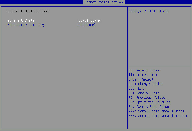
Table 119 Items on the Package C State Control submenu screen
|
Item |
Description |
Default |
|
Select the package C state limit. Options: · C0/C1 state. · C2 state. · C6 (non Retention)state. · C6 (Retention) state. · No Limit. · Auto. |
C0/C1 state |
|
|
PKG C-state Lat. Neg. |
Select Enabled or Disabled to enable or disable the package C-state latency negotiation feature. |
Disabled |
CPU Thermal Management submenu screen
Figure 166 shows the CPU Thermal Management submenu screen. The submenu items are described in Table 120.
Figure 166 CPU Thermal Management submenu screen
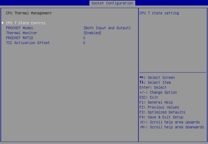
Table 120 Items on the CPU Thermal Management submenu screen
|
Item |
Description |
Default |
|
CPU T State Control |
CPU T-state control submenu, as shown in Figure 167. The submenu items are described in Table 121. |
N/A |
|
PROCHOT Modes |
Set the PROCHOT mode. Options: · Output-only. · Disabled. · Both Input and Output. · Input-only. |
Both Input and Output |
|
Thermal Monitor |
Select Enabled or Disabled to enable or disable processor temperature monitoring. |
Enabled |
|
PROCHOT RATIO |
Set the PROCHOT ratio. |
0 |
|
TCC Activation Offset |
Set the offset value from the default TCC activation temperature at which thermal control circuit (TCC) is activated. |
0 |
CPU T State Control submenu screen
Figure 167 shows the CPU T State Control submenu screen. The submenu items are described in Table 121.
Figure 167 CPU T State Control submenu screen

Table 121 Items on the CPU T State Control submenu screen
|
Item |
Description |
Default |
|
Select Enabled or Disabled to enable or disable software controlled T-state. |
Disabled |
|
|
T-State Throttle Level |
This item is available only when Software Controlled T-State is set to Enabled. Select the T-state throttle level. Options: · Disabled—Disables T-state throttling. · 6.25%. · 12.5%. · 18.75%. · 25.0%. · 31.25%. · 37.5%. · 43.75%. · 50.0%. · 56.25%. · 62.5%. · 68.75%. · 75.0%. · 81.25%. · 87.5%. · 93.75%. NOTE: The 6.25% and 12.5% options are unavailable for the B5700, B5800, and B7800. |
Disabled |
CPU Advanced PM Tuning submenu screen
Figure 168 shows the CPU Advanced PM Tuning submenu screen. The submenu items are described in Table 122.
Figure 168 CPU Advanced PM Tuning submenu screen
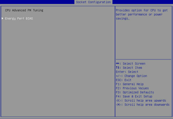
Table 122 Items on the CPU Advanced PM Tuning submenu screen
|
Item |
Description |
|
Energy and performance bias configuration submenu, on which you can configure the energy and performance policy for the system, as shown in Figure 169. The submenu items are described in Table 123. |
Energy Perf BIAS submenu screen
Figure 169 shows the Energy Perf BIAS submenu screen. The submenu items are described in Table 123.
Figure 169 Energy Perf BIAS submenu screen
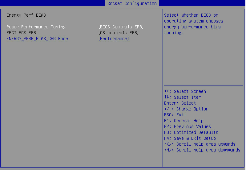
Table 123 Items on the Energy Perf BIAS submenu screen
|
Item |
Description |
Default |
|
Power Performance Tuning |
This item is inaccessible when Hardware P-States is set to Out of Band Mode. Select the operating system or the BIOS to control energy and performance bias tuning. Options: · OS Controls EPB. |
BIOS Controls EPB |
|
PECI PCS EPB |
This item is unconfigurable when Hardware P-States is set to Out of Band Mode or Power Performance Tuning is set to BIOS Controls EPB. Select whether to authorize PECI with the control over EPB. Options: · OS controls EPB—Enables the operating system to control EPB. · PECI controls EPB using PCS—Enables PECI to control EPB by using packet config space (PCS). |
OS controls EPB |
|
ENERGY_PERF_BIAS_CFG Mode |
This item is available only when Energy Performance Tuning is set to BIOS Controls EPB. Select an energy and performance bias option. The setting for this option overrides the energy and performance bias configured by the operating system. Options: · Performance—Provides maximum system performance (maximum cooling) at the expense of energy efficiency. · Balanced Performance—Provides optimum performance with good energy efficiency. · Balanced Power—Provides optimum power efficiency with good performance. · Power—Provides maximum power efficiency (maximum power saving) at the expense of system performance. |
Performance |
SOCKET RAPL Config submenu screen
Figure 170 shows the SOCKET RAPL Config submenu screen. The submenu items are described in Table 124.
Figure 170 SOCKET RAPL Config submenu screen
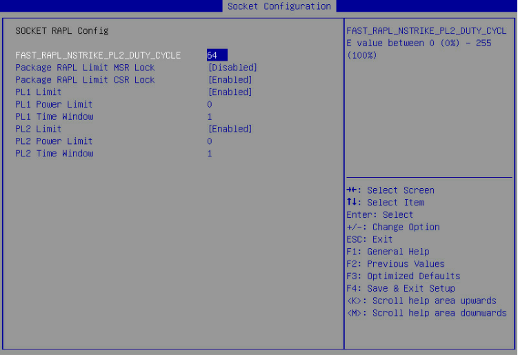
Table 124 Items on the SOCKET RAPL Config submenu screen
|
Item |
Description |
Default |
|
FAST_RAPL_NSTRIKE_PL2_DUTY_CYCLE |
Set FAST_RAPL_NSTRIKE_PL2_DUTY_CYCLE value. Value range: 0 to 255. |
64 |
|
Package RAPL Limit MSR Lock |
This item is available only when EIST (P-States) is set to Enabled. Select Enabled or Disabled to lock or unlock the PACKAGE_RAPL_LIMIT MSR register. |
Disabled |
|
Package RAPL Limit CSR Lock |
This item is available only when EIST (P-States) is set to Enabled. Select Enabled or Disabled to lock or unlock the PACKAGE_RAPL_LIMIT CSR register. |
Enabled |
|
PL1 Limit |
This item is available only when EIST (P-States) is set to Enabled. Select Enabled or Disabled to enable or disable power limit 1 (PL1), including PL1 power limit and PL1 time window. If this feature is disabled, the BIOS sets both PL1 power limit and PL1 time window to the default values. |
Enabled |
|
PL1 Power Limit |
This item is available only when EIST (P-States) is set to Enabled. Set the PL1 power limit in watts. If this item is set to 0, the fused value is programmed. Value range: 0 to the fused value. |
0 |
|
PL1 Time Window |
This item is available only when EIST (P-States) is set to Enabled. Set the PL1 time window value in seconds, which indicates the time window over which the TDP value must be maintained. If the value is set to 0, the fused value is programmed. Value range: 0 to 56. |
1 |
|
PL2 Limit |
This item is available only when EIST (P-States) is set to Enabled. Select Enabled or Disabled to enable or disable PL2 limit, including PL2 power limit and PL2 time window. If this feature is disabled, the BIOS sets both PL2 power limit and PL2 time window to the default values. |
Enabled |
|
PL2 Power Limit |
This item is available only when EIST (P-States) is set to Enabled. Set the PL2 power limit in watts. If this item is set to 0, the fused value is programmed. |
0 |
|
PL2 Time Window |
This item is available only when EIST (P-States) is set to Enabled. Set the PL2 time window value in seconds, which indicates the time window over which the TDP value must be maintained. If the value is set to 0, the fused value is programmed. Value range: 0 to 56. |
1 |
Server Management menu
Figure 171 and Figure 172 show the Server Management menu. From the menu, you can access the firmware information menu, and configure server management features such as the FRB-2 timer, OS watchdog timer, system event logging, HDM network configuration, and HDM user settings.
AC Restore Settings, Load HDM Default, HDM User Settings, and HDM Network Configuration items are unavailable for the B5700, B5800, and B7800 servers.
The menu items are described in Table 125.
Figure 171 Server Management menu screen (for all servers except for the B5700, B5800, and B7800)
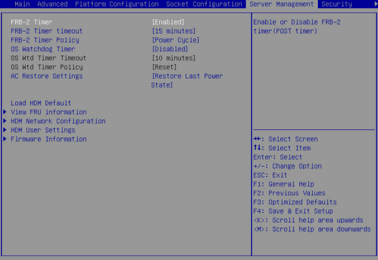
Figure 172 Server Management menu screen (for the B5700, B5800, and B7800)
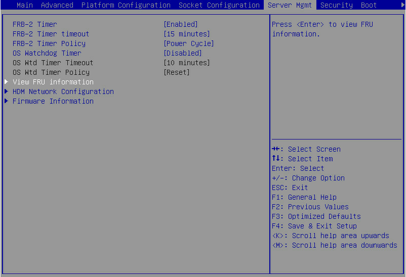
Table 125 Items on the Server Management menu screen
|
Item |
Description |
Default |
|
FRB-2 Timer |
Select Enabled or Disabled to enable or disable the FRB-2 timer. |
Enabled |
|
FRB-2 Timer timeout |
Set the timeout time for the FRB-2 timer. Options: · 3 minutes. · 4 minutes. · 5 minutes. · 6 minutes. · 10 minutes. · 15 minutes. · 20 minutes. |
15 Minutes |
|
FRB-2 Timer Policy |
Select the action to take when the FRB-2 timer expires. Options: · Do Nothing—No action is taken. · Reset—Reboots the system. · Power Down—Removes the main power from the system. · Power Cycle—Power cycles the system. |
Power Cycle |
|
OS Watchdog Timer |
Select Enabled or Disabled to enable or disable the OS watchdog timer. The OS watchdog timer starts when the OS begins to run. |
Disabled |
|
OS Wtd Timer Timeout |
This item is configurable only when OS Watchdog Timer is set to Enabled. Set the timeout time for the OS watchdog timer. Options: · 5 Minutes. · 10 Minutes. · 15 Minutes. · 20 Minutes. |
10 Minutes |
|
This item is configurable only when OS Watchdog Timer is set to Enabled. Select the action to take when the OS watchdog timer expires. Options: · Do Nothing—No action is taken. · Reset—Reboot the system. · Power Down—Removes the main power from the system. · Power Cycle—Power cycles the system. |
Reset |
|
|
This item is unavailable for the B5700, B5800, and B7800. Select the state to which the system is restored when the system AC power is restored. Options: · Always Power On—The system always returns to the power-on state. · Always Remain Off—The system always returns to the power-off state. · Restore Last Power State—The system returns to the power state when AC power was lost. |
Restore Last Power State |
|
|
Load HDM Default |
This item is unavailable for the B5700, B5800, and B7800 . To restore the factory default settings for HDM, select this item, and then press Enter. It takes one minute to restore the factory default HDM settings. After the restoration finishes, the server restarts automatically.
Do not configure HDM-related items before the server restarts. |
N/A |
|
View FRU information |
Access the submenu for viewing FRU information, as shown in Figure 173. The submenu items are described in Table 126. |
N/A |
|
HDM Network Configuration |
Access the network configuration submenu for HDM access, as shown in Figure 176. The submenu items are described in Table 127. |
N/A |
|
HDM User Settings |
Access the submenu for managing HDM user accounts, as shown in Figure 177. The submenu items are described in Table 128. |
N/A |
|
Firmware Information |
Access the submenu that displays the firmware information, as shown in Figure 180. The submenu items are described in Table 132. |
N/A |
View FRU information submenu
Figure 173 shows the View FRU information menu screen, on which you can view the FRU information. The menu items are described in Table 126.
Figure 173 View FRU information menu screen
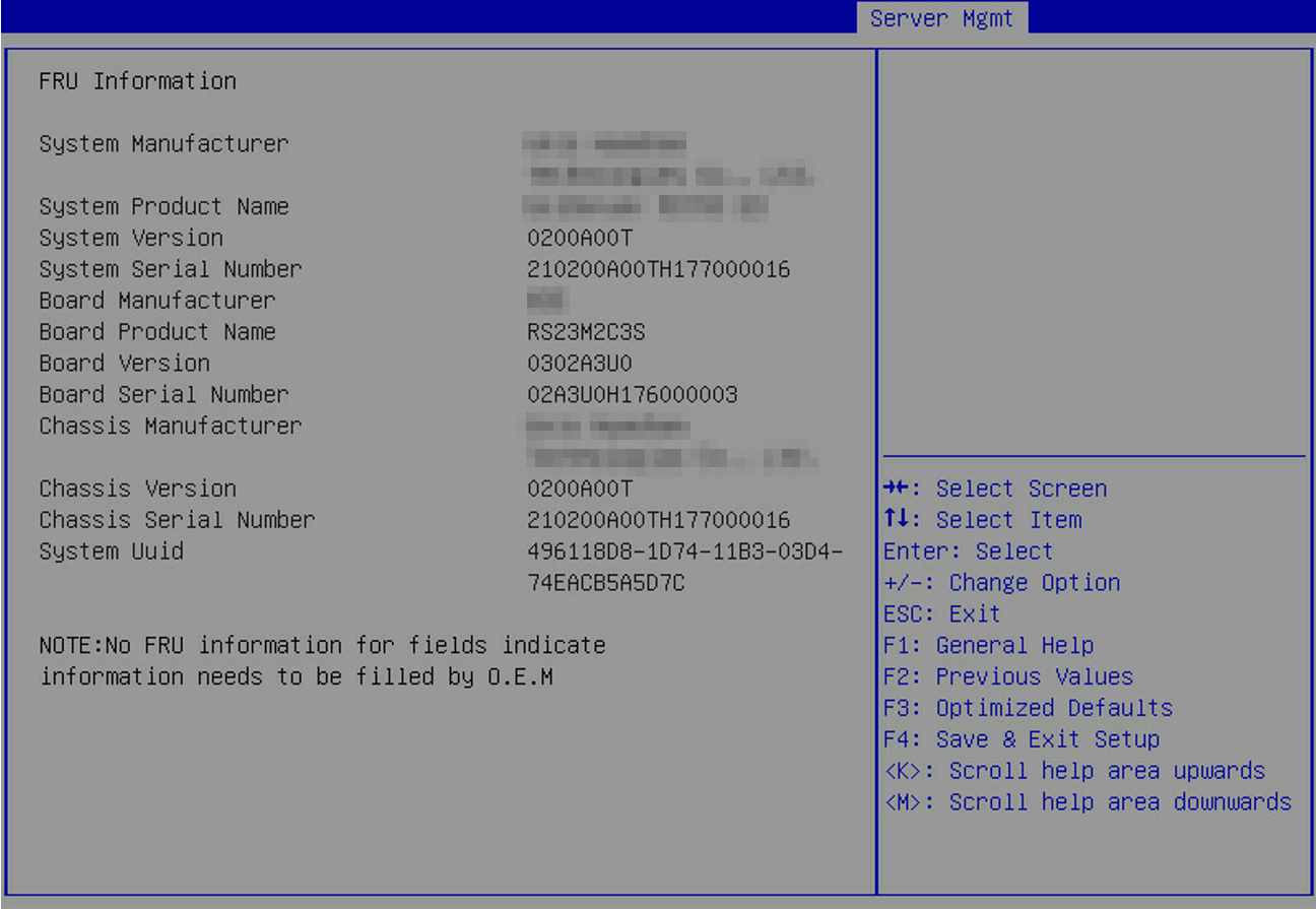
Table 126 Items on the View FRU information menu screen
|
Item |
Description |
|
System Manufacturer |
Displays the manufacturer of the system. |
|
System Product Name |
Displays the name of the system product. |
|
System Version |
Displays the version of the system. |
|
System Serial Number |
Displays the serial number of the system. |
|
Board Manufacturer |
Displays the manufacturer of the system board. |
|
Board Product Name |
Displays the product name of the system board. |
|
Board Version |
Displays the version of the system board. |
|
Board Serial Number |
Displays the serial number of the system board. |
|
Chassis Manufacturer |
Displays the manufacturer of the chassis. |
|
Chassis Version |
Displays the version of the chassis. |
|
Chassis Serial Number |
Displays the serial number of the system product. |
|
System Uuid |
Displays the UUID of the system. |
HDM Network Configuration submenu
Figure 174 and Figure 175 show the HDM Network Configuration menu screens, on which you can configure the HDM shared network port and the HDM dedicated network port. The menu items are described in Table 127.
HDM network configuration is not supported on the B5700, B5800, or B7800.
The configuration items for the HDM shared network port and the HDM dedicated network port are the same. This section uses the HDM shared network port as an example.
|
|
IMPORTANT: · Make sure the IP addresses of the HDM shared network port and the HDM dedicated network port are not in the same network segment. · The HDM dedicated network port for the B5700, B5800, and B7800 servers are unavailable, so the configuration items for the port are not displayed. |
Figure 174 HDM Network Configuration submenu screen (IPv4)

Figure 175 HDM Network Configuration submenu screen (IPv6)
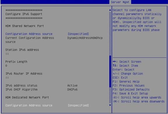
Table 127 Items on the HDM Network Configuration submenu screen
|
Item |
Description |
Default |
|
Configure IPv4 Support |
||
|
Sharelink Network |
Select whether to enable the HDM shared network port. Options: · Enabled. · Disabled. · Auto—The system automatically enables the HDM shared network port as needed. |
Enabled |
|
HDM Active/standby Mode |
Displays the enabling status of the active/standby mode. With the active/standby mode enabled, you can configure different VLAN settings for the HDM dedicated and shared network ports. With this mode enabled, the BIOS displays information only about the active port and allows users to configure only the active port. |
N/A |
|
VLAN Setting |
This item is unavailable for the B5700, B5800, and B7800. Select Enabled or Disabled to enable or disable VLAN. |
Disabled |
|
VLAN id |
This item is unavailable for the B5700, B5800, and B7800. This item is available only when VLAN Setting is set to Enabled. Set the VLAN ID. Value range: 2 to 4094. |
2 |
|
VLAN priority |
This item is unavailable for the B5700, B5800, and B7800. This item is available only when VLAN Setting is set to Enabled. Set the priority of the VLAN. Value range: 0 to 7. The greater the value, the higher the priority. When congestion occurs, the port preferentially forwards packets for the VLAN with a higher priority. |
0 |
|
Configuration Address source |
Select the IP address obtaining method for the port. This item is unavailable for the B5700, B5800, and B7800. Options: · Unspecified—Uses the current IP address obtaining method and settings. · Static—Uses the manually configured static IP address. · DynamicHdmDhcp—Obtains an IP address from a DHCP server. |
Unspecified |
|
Current Configuration Address source |
Displays the current IP address obtaining method. |
N/A |
|
Station IP Address |
This item is available only when the Configuration Address source item is set to Static. Set the IP address of the port. This setting takes effect only when the subnet mask is also set. |
N/A |
|
Subnet Mask |
This item is available only when Configuration Address source is set to Static. Set the subnet mask. This setting takes effect only when the station IP address is also set. |
N/A |
|
Station MAC Address |
Set the MAC address of the port. |
N/A |
|
Router IP Address |
This item is available only when Configuration Address source is set to Static. Set the gateway IP address. |
N/A |
|
Router MAC Address |
Set the gateway MAC address. |
N/A |
|
Configure IPv6 Support |
||
|
Configuration Address source |
This item is unavailable for the B5700, B5800, and B7800. Select the IPv6 address obtaining method for the port. Options: · Unspecified—Uses the current IP address obtaining method and settings. · Static—Uses the manually configured static IP address. · DynamicHdmDhcp—Obtains an IP address from a DHCP server. |
Unspecified |
|
Current Configuration Address source |
Displays the current IPv6 address obtaining method. |
N/A |
|
Station IPv6 address |
This item is available only when Configuration Address source is set to Static. Set the IPv6 address of the port. This setting takes effect only when the prefix length is also set. |
N/A |
|
Prefix Length |
This item is available only when the Configuration Address source item is set to Static. Set the subnet prefix length. Value range: 1 to 127. The value of 0 indicates that the prefix length is not set. This setting takes effect only when the station IPv6 address is also set. |
0 |
|
IPv6 Router IP Address |
This item is available only when Configuration Address source is set to Static. Set the gateway IPv6 address. Make sure the IPv6 address of the port and the gateway IPv6 address are on the same network segment. |
N/A |
|
IPv6 address status |
Displays the status of the IPv6 address. |
N/A |
|
IPv6 DHCP Algorithm |
Displays the DHCPv6 algorithm. |
N/A |
HDM User Settings submenu
Figure 176 shows the HDM User Settings menu screen, on which you can configure HDM users. The menu items are described in Table 128.
Figure 176 HDM User Settings submenu screen
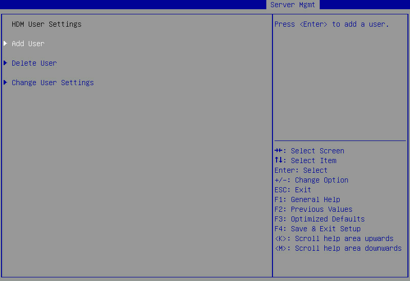
Table 128 Items on the HDM User Settings submenu screen
|
Item |
Description |
|
Add User |
Submenu for adding an HDM user account, as shown in Figure 177. The submenu items are described in Table 129. |
|
Delete User |
Submenu for deleting an HDM user account, as shown in Figure 178. The submenu items are described in Table 130. |
|
Change User Settings |
Submenu for changing the settings of an existing HDM user account, as shown in Figure 179. The submenu items are described in Table 131. |
Figure 177 Add User submenu screen
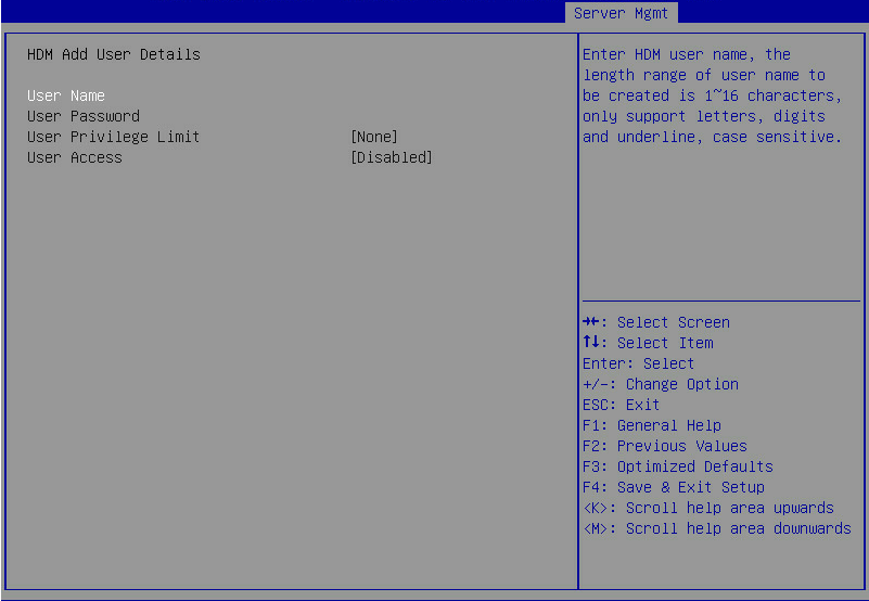
Table 129 Items on the Add User submenu screen
|
Item |
Description |
Default |
|
Specify the username, a case-sensitive string of 1 to 16 characters. The user name can contain letters, digits, and underscores (_). |
N/A |
|
|
User Password |
If password complexity check is enabled on the HDM Web interface, the password must meet the following requirements: · 8 to 20 characters in length. · Case sensitive. Valid characters are letters, digits, spaces, and the following special characters: ` ~ ! @ # $ % ^ & * ( ) _ + - = [ ] \ { } | ; ' : " , . / < > ? · Must contain characters from at least two of the following categories: uppercase letters, lowercase letters, and digits. · Must contain at least one space or special character. · Must not be identical to the username or the reverse of the username. If password complexity check is disabled on the HDM Web interface, the password must meet the following requirements: · 2 to 20 characters in length. · Case sensitive. Valid characters are letters, digits, spaces, and the following special characters: ` ~ ! @ # $ % ^ & * ( ) _ + - = [ ] \ { } | ; ' : " , . / < > ? By default, password complexity check is enabled on the HDM Web interface. For more information about enabling or disabling password complexity check, see HDM online help. |
N/A |
|
User Privilege Limit |
Select a user role, which represents a set of network and service access privileges. Options: · None—Retains the current privileges of the user account. · User—Assigns the user the read-only permission to HDM. · Operator—Assigns the user the read permission to all HDM features and write permission to a limited set of HDM features. · Administrator—Assigns the user read and write permissions to all HDM features. |
None |
|
User Access |
Select Enabled or Disabled to permit or deny the user's access to HDM Web interface. |
Disabled |
Figure 178 Delete User submenu screen
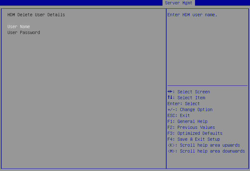
Table 130 Items on the Delete User submenu screen
|
Item |
Description |
|
User Name |
Enter the username of the HDM user account to be deleted. |
|
User Password |
Enter the password of the HDM user account to be deleted. |
Figure 179 Change User Settings submenu screen
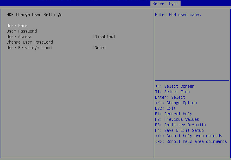
Table 131 Items on the Change User Settings submenu screen
|
Item |
Description |
Default |
|
User Name |
Enter the username of an existing HDM user account. |
N/A |
|
User Password |
Enter the password of the HDM user account. If the account logout threshold set in HDM (the default is 5 login failures) is reached, the user account is locked for the specified duration (the default is 5 minutes). |
N/A |
|
User Access |
Select Enabled or Disabled to permit or deny the user's access to HDM Web interface. This item is available only after you enter the correct username and password for the user account. |
Disabled |
|
Change User Password |
Specify a new password. This item is available only after you enter the correct username and password for the user account. The password must meet the complexity requirements described in Table 129. |
N/A |
|
User Privilege Limit |
Assign role-based privileges to the user account. This item is available only after you specify the correct user name and password of an HDM user account. Options: · None—Retains the current privileges of the user account. · User—Assigns the user the read-only permission to HDM. · Operator—Assigns the user the read permission to all HDM features and write permission to a limited set of HDM features. · Administrator—Assigns the user read and write permissions to all HDM features. |
None |
Firmware Information submenu
Figure 180 shows the Firmware Information menu screen. The menu items are described in Table 132.
Figure 180 Firmware Information submenu screen
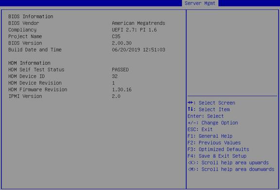
Table 132 Items on the Firmware Information submenu screen
|
Item |
Description |
|
BIOS Information |
|
|
BIOS Vendor |
Displays the BIOS vendor. |
|
Compliancy |
Displays the standard with which the BIOS is compliant. |
|
Project Name |
Displays the project name. |
|
BIOS Version |
Displays the BIOS version. |
|
Build Date and Time |
Displays the date and time of the BIOS build. |
|
HDM Information |
|
|
HDM Self Test Status |
Displays the HDM self test status. |
|
HDM Device ID |
Displays the HDM device ID. |
|
HDM Device Revision |
Displays the HDM device revision. |
|
HDM Firmware Revision |
Displays the HDM firmware revision. |
|
IPMI Version |
Displays the IPMI version. |
Security menu
Figure 181 and Figure 182 show the Security menu, on which you can configure security features such as setting the BIOS administrator and user passwords.
The menu items are described in Table 133.
Figure 181 Security menu screen (part 1)
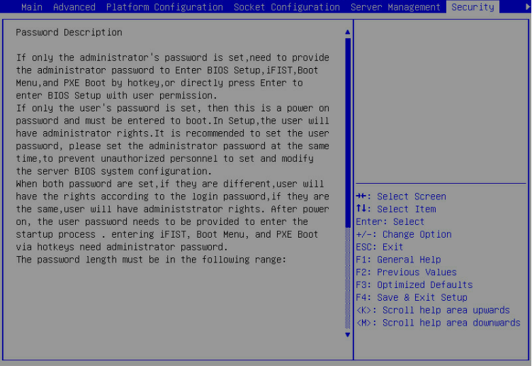
Figure 182 Security menu screen (part 2)
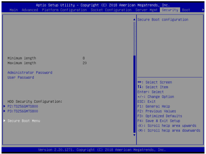
Table 133 Items on the Security menu screen
|
Item |
Description |
|
Password Description |
Displays the password description. |
|
Administrator Password |
Set the administrator password. For more information about restrictions for setting the administrator password, see "Setting the administrator password." |
|
User Password |
Set the user password. For more information about restrictions for setting the user password, see "Setting the user password." |
|
HDD Security Configuration |
Displays hard disk drives that support security configuration, for example, P2:TS256GMTS800. To configure security settings for a hard disk drive, select the disk drive and press Enter. The screen that opens is as shown in Figure 183, and the submenu items are described in Table 134. |
|
Secure Boot Menu |
This item is available only in UEFI boot mode. Access the submenu for configuring secure boot, as shown in Figure 184. The submenu items are described in Table 135. |
Figure 183 HDD Security Configuration submenu screen
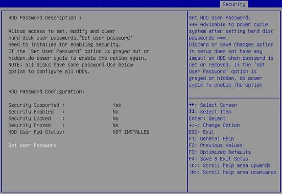
Table 134 Items on the HDD Security Configuration submenu screen
|
Item |
Description |
|
Security Supported |
Displays whether the hard disk drive supports security configuration. |
|
Security Enabled |
Displays whether an HDD user password has been set. If an HDD user password has been set, you must provide the password to unlock the hard disk drive before using it. |
|
Security Locked |
Displays whether the hard disk drive is locked. If the hard disk drive is locked, enter the user password to unlock it. |
|
Security Frozen |
Displays the security frozen status. Options: · Yes—The hard disk drive can be used but you cannot configure a user password for it. To change the security frozen status to No, you must power cycle the server. · No—The hard disk drive is not frozen. You can set the HDD user password. |
|
HDD User Pwd Status |
Displays whether an HDD user password is set (Installed) or not (Not Installed). |
|
Set User Password |
Set an HDD user password. If the HDD user password is set or removed, the setting on the BIOS will not affect the HDD password. If this item is inaccessible or hiden, you can power cycle the server for this item to become accessible. |
Figure 184 Secure Boot Menu submenu screen
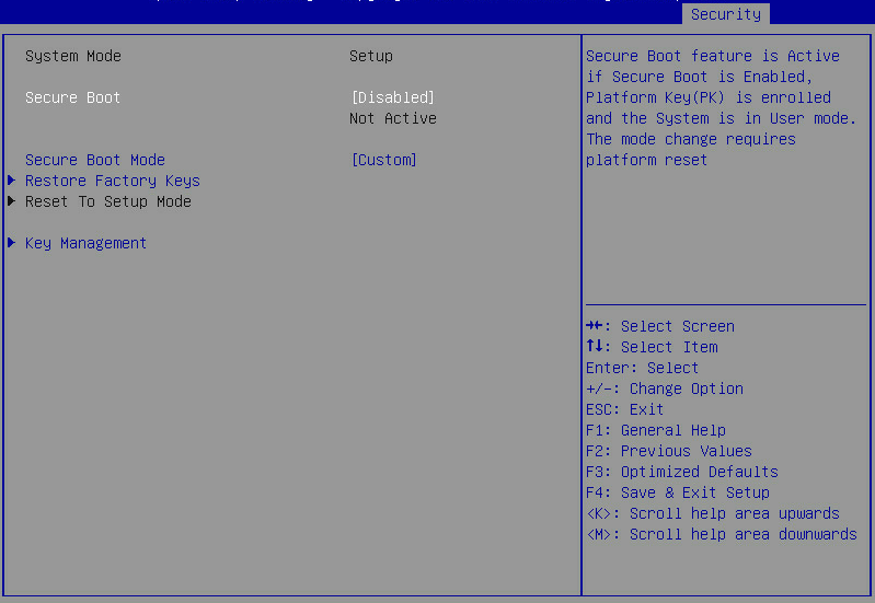
Table 135 Items on the Secure Boot menu screen
|
Item |
Description |
Default |
|
System Mode |
Displays the system mode. |
N/A |
|
Secure Boot |
Select Enabled or Disabled to enable or display secure boot. If Disabled is selected, Not Active is also displayed. If Enabled is selected, Active is also displayed. |
Disabled |
|
Secure Boot Mode |
Select a secure boot mode. Options: · Standard. · Custom. In custom boot mode, you can change the image execution policy and manage secure boot keys. |
Custom |
|
Restore Factory Keys |
Restore the factory default secure boot keys. |
N/A |
|
Reset To Setup Mode |
Reset the system mode to setup mode. |
N/A |
|
Key Management |
Access the submenu for key management, as shown in Figure 185. The submenu items are described in Table 136. |
N/A |
Figure 185 Key Management submenu screen
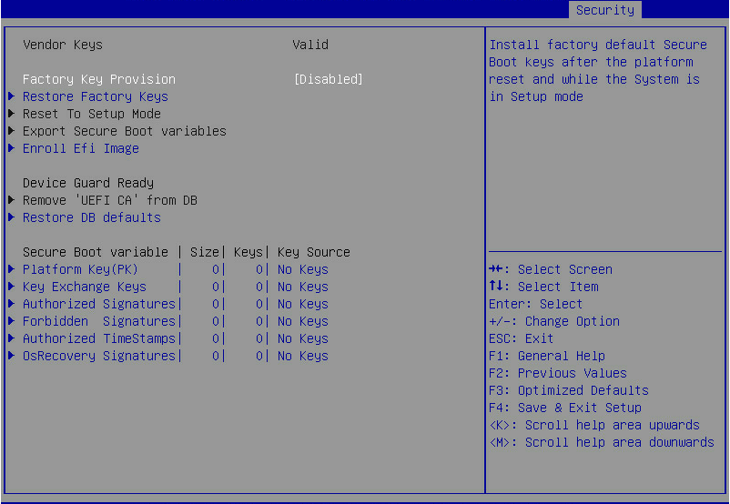
Table 136 Items on the Key Management submenu screen
|
Item |
Description |
Default |
|
Vendor Keys |
Displays whether the vendor keys have been modified. Options: · Valid—The vendor keys have not been modified and are valid. · Modified—The vendor keys have beed modified or deleted. |
N/A |
|
Factory Key Provision |
Select Enabled or Disabled to enable or disable provisioning the factory default keys when the system is in setup mode. |
Disabled |
|
Restore Factory Keys |
Access the submenu for restoring factory default keys. This operation forces the system to enter user mode and installs factory default secure boot keys. |
N/A |
|
Reset To Setup Mode |
Access the submenu for resetting the system mode to setup mode. |
N/A |
|
Export Secure Boot Variables |
Access the submenu for exporting all secure boot variables. |
N/A |
|
Enroll Efi Image |
Access the submenu for enrolling the EFI image. This operation enables secure boot for the image and enrolls a SHA256 hash of the PE image in the Authorized Signature Database (DB). |
N/A |
|
Device Guard Ready |
Indicates the server is ready for device guard. |
N/A |
|
Remove ‘UEFI CA’ from DB |
Access the submenu for removing UEFI CA from DB. |
N/A |
|
Restore DB defaults |
Access the submenu for restoring all DB variables to factory defaults. |
N/A |
|
Platform Key(PK) |
Access the submenu for managing the platform key. Option is Update. |
N/A |
|
Key Exchange Keys |
Access the submenu for managing key exchange keys. Options: · Update. · Append. |
N/A |
|
Authorized Signatures |
Access the submenu for configuring authorized signatures. Options: · Update. · Append. |
N/A |
|
Forbidden Signatures |
Access the submenu for managing forbidden signatures. Options: · Update. · Append. |
N/A |
|
Authorized TimeStamps |
Access the submenu for managing authorized timestamps. Options: · Update. · Append. |
N/A |
|
OsRecovery Signatures |
Access the submenu for configuring operating system recovery signatures. Options: · Update. · Append. |
N/A |
Boot menu
Figure 186 shows the Boot menu, on which you can configure boot settings such as the boot type and boot sequence.
The menu items are described in Table 137.
Figure 186 Boot menu screen
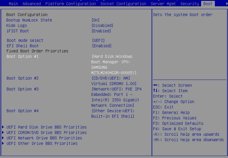
Table 137 Items on the Boot menu screen
|
Item |
Description |
Default |
|
Bootup NumLock State |
Select On or Off to turn on or turn off the NumLock key on the numeric keypad of the keyboard at system boot. |
On |
|
Hide Logo |
Select Enabled or Disabled to display or hide the logo on the boot screen. |
Disabled |
|
iFIST Boot |
Select Enabled or Disabled to enable or disable iFIST boot. If iFIST boot is disabled, the iFist item is not displayed on the BIOS startup screen as shown in Figure 2, and pressing F10 cannot boot iFIST. |
Enabled |
|
Boot mode select |
Select a boot mode. Options: · LEGACY. · UEFI. |
UEFI |
|
EFI Shell Boot |
Select Enabled or Disabled to enable or disable shell boot. |
Disabled |
|
Displays the prioritized list of bootable devices from which the system can boot. In legacy mode, a drive is displayed in the list only if it has the highest boot priority (BBS priority) among all the drives of the same type. To display a drive in this list, enter the BBS priorities submenu for the drive type, and then set this drive as the first boot option. |
N/A |
|
|
Boot Option #1 |
Set the first boot option. To disable the first boot option, select Disabled for this item. |
N/A |
|
Boot Option #2 |
Set the second boot option. To disable the second boot option, select Disabled for this item. |
N/A |
|
Boot Option #3 |
Set the third boot option. To disable the third boot option, select Disabled for this item. |
N/A |
|
Boot Option #4 |
Set the fourth boot option. To disable the fourth boot option, select Disabled for this item. |
N/A |
|
UEFI Hard Disk Drive BBS Priorities |
This item is available only in UEFI boot mode. Access the submenu for configuring the boot priorities of hard disk drives, as shown in Figure 187. The submenu items are described in Table 138. |
N/A |
|
Hard Disk Drive BBS Priorities |
This item is available only in legacy boot mode. Access the submenu for configuring the boot priorities of hard disk drives. |
N/A |
|
UEFI CDROM/DVD Drive BBS Priorities |
This item is available only in UEFI boot mode and when one or more CD- or DVD-ROM drives are connected. Access the submenu for configuring the boot priorities of connected CD- or DVD-ROM drives, as shown in Figure 188. The submenu items are described in Table 139. |
N/A |
|
CDROM/DVD Drive BBS Priorities |
This item is available only in legacy boot mode and when one or more CD- or DVD-ROM drives are connected. Access the submenu for configuring the boot priorities of connected CD- or DVD-ROM drives. |
N/A |
|
UEFI Network Drive BBS Priorities |
This item is available only in UEFI boot mode. Access the submenu for configuring the boot priorities of available network drives, as shown in Figure 189. The submenu items are described in Table 140. |
N/A |
|
Network Drive BBS Priorities |
This item is available only in legacy boot mode. Access the submenu for configuring the boot priorities of available network drives. |
N/A |
|
UEFI Other Drive BBS Priorities |
Set the boot device priority sequence from the available UEFI other drives. Options: · Embedded UEFI shell. This option is available only when EFI Shell Boot is set to Enabled. · USB devices with the capacity less than 32 GB. · Virtual drives. Access the submenu for configuring the boot priorities of other devices, as shown in Figure 190. The submenu items are described in Table 141. |
N/A |
Figure 187 UEFI Hard Disk Drive BBS Priorities
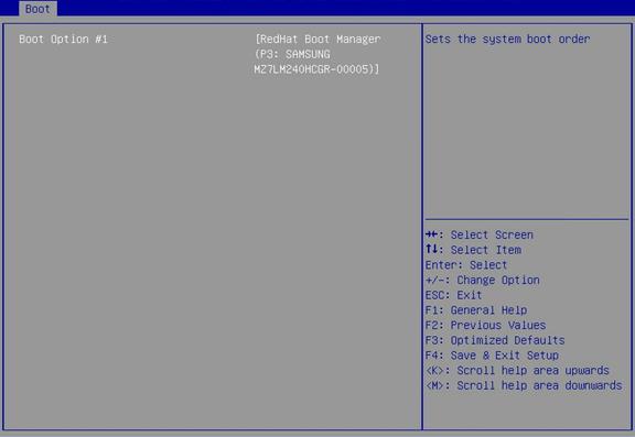
Table 138 Items on the UEFI Hard Disk Drive BBS Priorities submenu screen
|
Item |
Description |
|
Boot Option #1 |
Select a hard disk as the first boot option. To disable this boot option, select Disabled. |
|
The number of available options varies by server configuration. |
|
Figure 188 UEFI CDROM/DVD Drive BBS Priorities screen menu
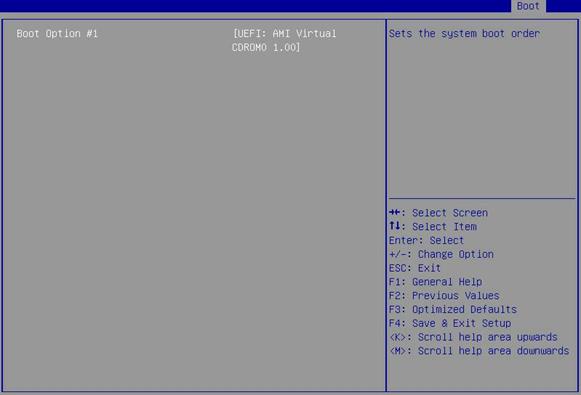
Table 139 Items on the UEFI CDROM/DVD Drive BBS Priorities submenu screen
|
Item |
Description |
|
Boot Option #1 |
Select a CD- or DVD-ROM drive as the first boot option. To disable this boot option, select Disabled. |
|
The number of available options varies by server configuration. |
|
Figure 189 UEFI Network Drive BBS Priorities submenu screen
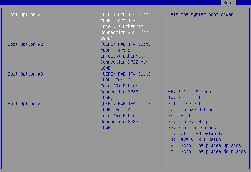
Table 140 Items on the UEFI Network Drive BBS Priorities submenu screen
|
Item |
Description |
|
Boot Option #1 |
Select a PXE boot device as the first boot option. To disable this boot option, select Disabled. |
|
Boot Option #2 |
Select a PXE boot device as the second boot option. To disable this boot option, select Disabled. |
|
Boot Option #3 |
Select a PXE boot device as the third boot option. To disable this boot option, select Disabled. |
|
Boot Option #4 |
Select a PXE boot device as the fourth boot option. To disable this boot option, select Disabled. |
|
The number of available options varies by server configuration. |
|
Figure 190 UEFI Other Drive BBS Priorities submenu screen
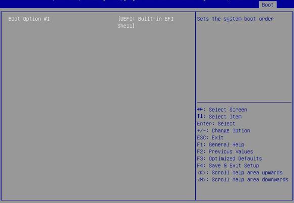
Table 141 Items on the UEFI Other Drive BBS Priorities submenu screen
|
Item |
Description |
|
Boot Option #1 |
Select the other type of boot devices as the first boot option. To disable this boot option, select Disabled. |
|
The number of available options varies by server configuration. |
|
Save & Exit menu
Figure 191 shows the Save & Exit menu, on which you can save the BIOS parameter settings and exit BIOS.
The menu items are described in Table 142.
Figure 191 Save & Exit menu screen
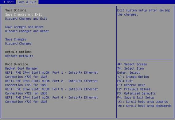
Table 142 Items on the Save & Exit menu screen
|
Item |
Description |
|
Save Options |
|
|
Exit with changes saved. |
|
|
Discard Changes and Exit |
Exit without saving changes. |
|
Save Changes and Reset |
Restart the server with changes saved. |
|
Discard Changes and Reset |
Restart the server without saving changes. |
|
Save Changes |
Save changes without exiting the BIOS. |
|
Discard Changes |
Discard changes without exiting the BIOS. |
|
Default Options |
|
|
Restore Defaults |
Restore the factory-default settings. |
|
Select a boot device option and press Enter to boot from that device. This setting is a one-time setting that takes effect only at the next boot. Subsequent boots will use the boot order configured on the Boot menu screen. |
|
|
UEFI: PXE IPv4 Slot9 mLOM: Port x – Intel(R) Ethernet Connection X722 for 1GbE |
This item is available only in UEFI boot mode. Select this item as a boot option for one-time boot override. |
|
IBA 40G Slot 3D00 v1066 |
This item is available only in legacy boot mode. Select this item as a boot option for one-time boot override. |
Acronyms and abbreviations
Table 143 Acronyms and abbreviations
|
Term |
Definition |
|
A |
|
|
ACPI |
Advanced Configuration and Power Interface |
|
ADR |
Asynchronous Dram Refresh |
|
AHCI |
Advanced Host Controller Interface |
|
B |
|
|
BIOS |
Basic Input Output System |
|
C |
|
|
COD |
Cluster On Die |
|
CFG |
Configure |
|
CSM |
Compatibility Support Module |
|
D |
|
|
DCU |
Drive Control Unit |
|
DMA |
Direct Memory Access |
|
DRAM |
Dynamic Random Access Memory |
|
DCPMM |
Intel® Optane™ DC PMEM module |
|
E |
|
|
ECC |
Error Checking and Correcting |
|
EFI |
Extensible Firmware Interface |
|
EIST |
Enhanced Intel SpeedStep Technology |
|
EMS |
Emergency Management Services |
|
EMCA |
Enhanced Machine Check Architecture |
|
G |
|
|
GPU |
Graphics Processing Unit |
|
H |
|
|
HBA |
Host Bus Adapter |
|
HDM |
H3C Device Management |
|
IDE |
Integrated Drive Electronics |
|
IIO |
Integrated I/O Module |
|
IMC |
Integrated Memory Controller |
|
IRQ |
Interrupt Request |
|
iSCSI |
Internet Small Computer System Interface |
|
L |
|
|
LLC |
Last Level Cache |
|
LLDP |
Link Layer Discovery Protocol |
|
LUN |
Logical Unit Number |
|
M |
|
|
MAC |
Media Access Control |
|
MCTP |
Management Component Transport Protocol |
|
ME |
Management Engine |
|
MMIO |
Memory mapping I/O |
|
MRC |
Memory Reference Code |
|
N |
|
|
NIC |
Network Interface Controller |
|
NMI |
Non-Maskable Interrupt |
|
NUMA |
Non Uniform Memory Access |
|
O |
|
|
OS |
Operating System |
|
PCH |
Platform Controller Hub |
|
PCI |
Peripheral Component Interface |
|
PCIe |
Peripheral Component Interconnect Express |
|
PCU |
Power Controller Unit |
|
PECI |
Platform Environment Control Interface |
|
PK |
Platform Key |
|
POR |
Plan Of Record |
|
POST |
|
|
PXE |
Preboot Execute Environment |
|
R |
|
|
RAID |
Redundant Arrays of Independent Disks |
|
RAPL |
Running Average Power Limit |
|
RAS |
Reliability, Availability, Serviceability |
|
RFO |
Request For Ownership |
|
ROM |
Read-Only Memory |
|
RTS/CTS |
Request To Send/Clear To Send |
|
S |
|
|
SAS |
Serial Attached SCSI |
|
SATA |
Serial Advanced Technology Attachment |
|
SCSI |
Small Computer System Interface |
|
SEL |
System Event Log |
|
SMI |
System Management Interrupt |
|
SR-IOV |
Single-Root I/O Virtualization |
|
SMBIOS |
System Management BIOS |
|
T |
|
|
TCM |
Trusted Cryptography Module |
|
TDP |
Thermal Design Power |
|
TPM |
Trusted Platform Module |
|
TXT |
Trusted Execution Technologies |
|
U |
|
|
UEFI |
Unified Extensible Firmware Interface |
|
UID |
Unit Identification |
|
UPI |
Ultra Path Interconnect |
|
V |
|
|
VT-d |
Intel Virtualization Technology For Directed I/O |
|
VGA |
Video Graphics Array |
|
X |
|
|
eXtensible Host Controller Interface |
|
