- Released At: 08-05-2025
- Page Views:
- Downloads:
- Table of Contents
- Related Documents
-
|
|
|
Hardening Comware 7 H3C MSR & VSR & SR6600[SR6600-X] Router Series |
|
|
|
|
|
|
Copyright © 2019 New H3C Technologies Co., Ltd. All rights reserved.
No part of this manual may be reproduced or transmitted in any form or by any means without prior written consent of New H3C Technologies Co., Ltd.
Except for the trademarks of New H3C Technologies Co., Ltd., any trademarks that may be mentioned in this document are the property of their respective owners.
The information in this document is subject to change without notice.
Contents
Threats to the management and control planes
Hardening the management plane
Securing console/AUX/USB access
User management and access control
Using RBAC to control user access permissions
Using AAA to secure user access and user management
Using command authorization to secure command access
Disabling password recovery capability·
Configuring memory alarm thresholds
Securing spanning tree networks
Enabling dynamic ARP entry check
Preventing ARP spoofing attacks
Source MAC-based ND attack detection
DHCP starvation attack protection
DHCP relay entry management on the DHCP relay agent
DHCP proxy on the DHCP relay agent
Disabling the TCP Timestamps option encapsulation
Securing IGMP snooping and MLD snooping
Control plane packet rate limiting and packet-drop logging
ADVPN VAM protocol packet security
Authentication and encryption algorithms
Hardware and feature compatibility
Enabling CAPWAP tunnel encryption
Configuring WLAN client access control
Configuring WLAN authentication to secure user access
Managing user access rights for AC hierarchy networks
Authenticating high availability protocol packets
Securing VRRP packet authentication
BFD control packet authentication
Configuring the NTP access right
Configuring security association and tunnel encryption for NEMO
Suppressing storms and controlling storms
Dropping unknown multicast data packets
MAC address security management
Configuring blackhole MAC address entries·
Disabling MAC address learning
Configuring GRE security mechanisms·
Configuring IPsec to secure ADVPN packets·
Configuring IPsec to secure mGRE packets·
Packet filtering & Traffic filtering
Configuring the voice VLAN security mode
DoS attack detection and defense
About this document
This document helps you improve the overall network security by hardening the Comware 7 network devices.
Audience
This document is intended for:
· Network planners.
· Field technical support and servicing engineers.
· Network administrators.
Port numbering in examples
The port numbers in this document are for illustration only and might be unavailable on your device.
Prerequisites
This document is not restricted to specific software or hardware versions.
The configuration examples were created and verified in a lab environment, and all the devices were started with the factory default configuration. When you are working on a live network, make sure you understand the potential impact of every command on your network.
This document provides only generic technical information, some which might not apply to your devices.
Overview
The functions of Comware 7 network devices are categorized into the management plane, control plane, and data plane. This document helps you improve the overall network security by hardening the security of these three planes.
Security threats
Threats to the management and control planes
The management plane manages administrative access to the device through applications and protocols such as Telnet, SSH, Web, and SNMP. Protecting the management plane against unauthorized access and attacks is essential to the security of the entire network. If the management plane is breached,
The control plane contains applications and protocols that are running between devices to maintain the functionality of the network architecture and facilitate the functions of the data plane. For example, routers run routing protocols such as OSPF or BGP between them to learn about routes and switches run protocols such as spanning tree protocols to learn about various paths.
Security threats to the management and control planes of a network device come from various sources, including malicious users, compromised remote network devices, and an inappropriate security policy.
The following are common security threats to the management and control planes:
· Unauthorized access.
An attacker can gain access to the device by forging the identity of the administrator or launching management session replay attacks or man-in-the-middle attacks.
To protect administrative sessions to the device, configure strong identity authentication, establish secure access channels, and perform anti-replay and message integrity check. In addition, enable operations and security event logging to record and audit administrative behavior of users.
· Weak password.
A weak password is easy to crack. As a best practice, configure a password policy to require strong passwords for administrative access.
· Sensitive information leaking
Important or confidential information might be eavesdropped on the transmission path. Stored contents might be leaked when the storage device is transferred or replaced.
To guarantee the confidentiality of sensitive information:
¡ Avoid establishing insecure administrative sessions to the device by using protocols such as Telnet, FTP, TFTP, or HTTP. Instead, establish secure administrative sessions by using protocols such as SSH, IPsec, SFTP, and HTTPS.
¡ Encrypt the startup configuration file.
¡ Format the removed storage devices before you dispose of them, making sure the removed data cannot be restored.
· Message tampering and forging.
An attacker might tamper with or replay messages on the transmission path to inject malicious data or tamper with data on a network device. For example, attackers can tamper with routing protocol packets to influent the path of packets.
To protect the control plane, configure security services including integrity check and anti-replay.
· Distributed denial of service (DDoS) attacks.
In a DDoS attack, the attacker sends a large number of packets to exhaust the device resources, including CPU, memory, sessions, and bandwidth. Busy with handling illegitimate packets, the victim network device will be unable to provide forwarding services to users.
To protect a network device against DDoS attacks:
¡ Use a whitelist to identify trusted remote devices.
¡ Use a blacklist to block traffic from suspicious remote devices.
¡ Limit the rate at which traffic is sent to the control plane.
· Misconfiguration.
Misconfiguration might result in incorrect access control, permission assignment, or authorization.
To avoid security risks introduced because of misconfiguration:
¡ Verify the configuration before deploying it.
¡ Constantly audit the device behavior after the configuration is deployed, for example, by reviewing the operation log or system log.
Threats to the data plane
The data plane forwards data from source to destination. If the data plane was attacked, the forwarding performance would downgrade significantly and in the worst case, malicious packets would spread in the network.
Common security threats to the data plane include:
· Malformed packet attacks.
Attackers can exploit the packet processing vulnerabilities in the data plane to attack the device, causing the device to malfunction or crash.
To detect and prevent potential malformed packet attacks, enable attack detection and prevention.
· DDoS attacks.
DDoS attack occurs when an attacker sends a large number of packets to exhaust the device resources, including CPU, memory, connections, and bandwidth.
To protect the device against such attacks, configure resource usage thresholds to ensure that the device always has resources for normal services. In addition, authenticate users, identify illegitimate traffic, and limit the traffic of unrecognizable users.
· Identity spoofing.
Identity spoofing is part of many attacks. Identifying spoofed identities can effectively prevent attacks. However, the openness of the network makes this job very difficult, especially on the data plane.
To identify spoofed identifies on the data plane, you can use security features such as IP source guard, SYN Cookie, ARP attack protection, and ND attack defense.
· Message tampering and forging.
Message integrity is critical to network functionality. False data might cause network failure or even network paralysis.
As a best practice, use security protocols such as IPsec and MACsec to protect data flows in the network. Securing mechanisms include integrity check, confidentiality offset, and identity authentication.
Security architecture
Figure 1 shows the security architecture of Comware.
Figure 1 Comware security architecture
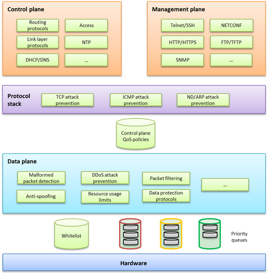
This security architecture offers multilayer protection to ensure overall security.
If a device offers hardware forwarding, its hardware layer uses whitelist and priority queuing mechanisms to protect the control and management planes from DoS or DDoS attacks. These mechanisms handle packets destined for the local device as follows before delivering them from the hardware layer to the CPU:
¡ Whitelist—If a source is trustworthy and a session has been established to it, the source is added to the whitelist. The hardware layer preferentially delivers all its packets to the CPU.
¡ Priority queues—If a packet is not from a source in the whitelist, the hardware layer enques the packet in a priority queue depending on its protocol. Packets in any priority queues have lower priority than packets from a whitelist source.
· On the forwarding plane, Comware provides a variety of security features, including:
¡ Malformed packet detection.
¡ Packet filtering.
¡ Anti-spoofing, for example uRPF and IP source guard.
¡ DDoS attack defense.
¡ Resource usage limits, including connection limit and ARP/ND table entry limit.
¡ Data protection protocols, such as IPsec and MACsec.
· On the control and management planes, Comware provides security features including:
¡ QoS policy configurable to limit or filter traffic delivered to the control or management plane. For example, you can limit the rate of traffic sent to the control plane. You can also configure application security features to protect the control plane against attacks such as TCP attacks, ICMP/ICMPv6 attacks, ARP attacks, and ND attacks.
¡ Security protocols or options specific to service modules for enhanced service protection.
Basic hardening principles
Enforcing security features aligned with your network environment, security needs, and protected objects is critical to the effective protection of your network. Hardening a network device with as many security features as you have would increase costs, add configuration complexities, and impact device performance without making it more secure.
To effectively protect a network device:
1. Identify major threats and risks that the network device is facing and sort them by their impact on your business.
2. Select and phase in security features to protect the network device against the identified threats and risks by their significance.
3. Constantly evaluate the protection effect after a security feature or a set of security features is introduced.
4. Depending on the evaluation conclusion, change or phase in security features until the security risks to the business are mitigate to an acceptable or minimum level.
Hardening the management plane
Device access control
Securing console/AUX/USB access
Hardware and feature compatibility
|
Hardware |
USB login compatibility |
|
SR6600 router series SR6600-X router series |
Yes |
|
MSR router series |
Yes |
|
VSR virtual routers |
No |
Security threats
(Devices that have both console and AUX ports.) By default, console login and AUX login are both enabled. Console login does not require authentication. AUX login requires password authentication but the password is null, which allows you to log in by pressing Enter at the prompt for a password. The user role is network-admin for a console user and is network-operator for an AUX user.
(Devices that have an AUX port but do not have a console port.) By default, AUX login and USB login are enabled and do not require authentication. The user role is network-admin for an AUX or USB user.
Hardening recommendations
Configure one of the following authentication modes in user line view or line class view immediately after you log in to the device for the first time:
· Password authentication—Requires a password for authentication. A user must provide the correct password at login. This authentication mode is not supported in FIPS mode.
· Scheme authentication—Uses the AAA module to provide local or remote login authentication. A user must provide the correct username and password at login.
After configuring password or scheme authentication, keep the password or username and password securely.
Restrictions and guidelines
A console, AUX, or USB login configuration change takes effect only on users who log in after the change is made. It does not affect users who are already online when the change is made.
In FIPS mode, the device supports only scheme authentication. You cannot disable authentication or configure password authentication.
Examples
· Secure console login:
# Configure password authentication in console line view.
<Sysname> system-view
[Sysname] line console 0
[Sysname-line-console0] authentication-mode password
# Specify a password.
[Sysname-line-console0] set authentication password simple Plat&0631!
Alternatively:
# Configure scheme authentication in console line view.
<Sysname> system-view
[Sysname] line console 0
[Sysname-line-console0] authentication-mode scheme
[Sysname-line-console0] quit
# Configure authentication methods for login users in ISP domain view.
To use local authentication, configure a local user and set the relevant attributes. To use remote authentication, configure a RADIUS, HWTACACS, or LDAP scheme. For more information, see AAA in Security Configuration Guide.
· Secure AUX login:
# Configure password authentication in AUX line view.
<Sysname> system-view
[Sysname] line aux 0
[Sysname-line-aux0] authentication-mode password
# Specify a password.
[Sysname-line-aux0] set authentication password simple Plat&0631!
Alternatively:
# Configure scheme authentication in AUX line view.
<Sysname> system-view
[Sysname] line aux 0
[Sysname-line-aux0] authentication-mode scheme
# Configure authentication methods for login users in ISP domain view.
To use local authentication, configure a local user and set the relevant attributes. To use remote authentication, configure a RADIUS, HWTACACS, or LDAP scheme. For more information, see AAA in Security Configuration Guide.
· Secure USB login:
# Configure password authentication in USB line view.
<Sysname> system-view
[Sysname] line usb 0
[Sysname-line-usb0] authentication-mode password
# Specify a password.
[Sysname-line-usb0] set authentication password simple Plat&0631!
# Configure scheme authentication in USB line view.
<Sysname> system-view
[Sysname] line usb 0
[Sysname-line-usb0] authentication-mode scheme
# Configure authentication methods for login users in ISP domain view.
To use local authentication, configure a local user and set the relevant attributes. To use remote authentication, configure a RADIUS, HWTACACS, or LDAP scheme. For more information, see AAA in Security Configuration Guide.
Securing Stelnet access
Security threats
Stelnet users might face the following security threats:
· An attacker might scan for and obtain the SSH service port number, and then try to Stelnet to the device again and again to log in to the device.
· The device supports a limited number of concurrent SSH users. An attacker might use spoofed IP addresses and valid usernames and passwords to Stelnet to the device, making legal users unable to Stelnet to the device.
Hardening recommendations
To protect the device against the security threats, you can use the following security policies:
· Password authentication
The SSH server authenticates a client by using the AAA mechanism. The password authentication process is as follows:
a. The client sends the server an authentication request that includes the encrypted username and password.
b. The server decrypts the request, verifies the username and password locally or through remote AAA authentication, and informs the client of the authentication result.
· Publickey authentication
The SSH server authenticates a client by verifying the digital signature of the client. The publickey authentication process is as follows:
c. The client sends the server a publickey authentication request that includes the username, public key, and public key algorithm name.
If the digital certificate of the client is required in authentication, the client also encapsulates the digital certificate in the authentication request. The digital certificate carries the public key information of the client.
d. The server verifies the client's public key.
- If the public key is invalid, the server informs the client of the authentication failure.
- If the public key is valid, the server requests the digital signature of the client. After receiving the signature, the server uses the public key to verify the signature and informs the client of the authentication result.
· Password-publickey authentication
The SSH server requires SSH2 clients to pass both password authentication and publickey authentication. An SSH1 client only needs to pass either authentication.
· Disabling the Stelnet service
Disable the Stelnet service when it is not required. The SSH service port number is easy to be found by a scanning attacker.
· Changing the SSH service port number to a non-well-known port number
By default, the SSH service port number is well-known port number 22, which is an easy target. Changing the SSH service port number reduces the risk to be attacked.
· Configuring SSH access control
Apply an ACL to control access to the SSH server, so only IPv4 SSH clients permitted by the ACL can access the SSH server.
· Limiting the number of concurrent SSH users
If the maximum number of concurrent SSH users is reached, the SSH server rejects additional connection requests.
Restrictions and guidelines
A Stelnet login configuration change takes effect only on users who log in after the change is made. It does not affect users who are already online when the change is made.
Examples
· # Configure password authentication for an SSH user.
<Sysname> system-view
[Sysname] ssh user client001 service-type stelnet authentication-type password
# For local authentication, configure a local user on the SSH server. For remote authentication, configure an SSH user on a remote authentication server, for example, a RADIUS server. For more information, see AAA in Security Configuration Guide.
· # Configure publickey authentication for an SSH user.
<Sysname> system-view
[Sysname] ssh user client002 service-type stelnet authentication-type publickey assign publickey clientkey
# Create a local user that uses the same username and assign a working directory and user roles to the user. For more information, see AAA in Security Configuration Guide.
· # Disable the Stelnet service.
<Sysname> system-view
[Sysname] undo ssh server enable
· # Change the SSH service port number to a non-well-known port number.
<Sysname> system-view
[Sysname] ssh server port 1025
· # Apply an ACL to permit only SSH access from 1.1.1.1.
<Sysname> system-view
[Sysname] acl basic 2001
[Sysname-acl-ipv4-basic-2001] rule permit source 1.1.1.1 0
[Sysname-acl-ipv4-basic-2001] quit
[Sysname] ssh server acl 2001
· # Set the maximum number of concurrent SSH users.
<Sysname> system-view
[Sysname] aaa session-limit ssh 16
Securing modem dial-in
Hardware and feature compatibility
|
Hardware |
Modem dial-in compatibility |
|
SR6600 router series SR6600-X router series |
Yes |
|
MSR router series |
Yes |
|
VSR virtual routers |
No |
Security threats
The device supports using a pair of modems to remotely connect the serial port of a PC to the console or AUX port of the device over PSTN. The user lines for modem dial-in users are AUX lines. By default, modem dial-in to the console port is enabled and does not require authentication. Modem dial-in to the AUX port is enabled and requires password authentication. However, the password is null, and you can log in by pressing Enter at the prompt for a password. Attackers might remotely dial in to the device and manage the device.
Hardening recommendations
Configure one of the following authentication modes in console and AUX user line views or line class views immediately after you log in to the device for the first time:
· Password authentication—Requires a password for authentication. A user must provide the correct password at login. This authentication mode is not supported in FIPS mode.
· Scheme authentication—Uses the AAA module to provide local or remote login authentication. A user must provide the correct username and password at login.
After configuring password or scheme authentication, keep the password or username and password securely.
Restrictions and guidelines
An AUX login configuration change takes effect only on users who log in after the change is made. It does not affect users who are already online when the change is made.
In FIPS mode, the device supports only scheme authentication. You cannot disable authentication or configure password authentication.
Examples
# Configure password authentication in AUX line view.
<Sysname> system-view
[Sysname] line aux 0
[Sysname-line-aux0] authentication-mode password
# Specify a password.
[Sysname-line-aux0] set authentication password simple Plat&0631!
Alternatively:
# Configure scheme authentication in AUX line view.
<Sysname> system-view
[Sysname] line aux 0
[Sysname-line-aux0] authentication-mode scheme
# Configure authentication methods for login users in ISP domain view.
To use local authentication, configure a local user and set the relevant attributes. To use remote authentication, configure a RADIUS, HWTACACS, or LDAP scheme. For more information, see AAA in Security Configuration Guide.
Securing SNMP access
Security threats
The device might face the following threats when it acts as an SNMP agent:
· An attacker might steal SNMPv1 or SNMPv2c community names and use them to access the device.
· An attacker might eavesdrop on and tamper with SNMP packets.
· Legal users of NMSs might perform tasks mistakenly, causing the device unable to operate correctly.
Hardening recommendations
To protect the device against the security threats, you can use the following security policies:
· Disabling the SNMP agent when it is not required. By default, the SNMP agent is disabled.
· Using SNMPv3, which is more secure than SNMPv1 and SNMPv2c. SNMPv3 uses a user-based security model to secure SNMP communication. You can configure authentication and privacy mechanisms to authenticate and encrypt SNMP packets for integrity, authenticity, and confidentiality.
· Using the following modes to control access to MIB objects:
¡ View-based Access Control Model—VACM mode controls access to MIB objects by assigning MIB views to SNMP communities or users.
¡ Role based access control—RBAC mode controls access to MIB objects by assigning user roles to SNMP communities or users.
RBAC mode controls access on a per MIB object basis, and VACM mode controls access on a MIB view basis. As a best practice to enhance MIB security, use the RBAC mode.
· Applying an ACL to permit only legal NMSs to access the SNMP agent.
· Encapsulating security parameters in notifications to allow only NMSs that satisfy the requirements can receive the notifications.
Restrictions and guidelines
For an NMS to connect to the device, make sure they use the same SNMP version and community name (or username and password).
Examples
· Disable the SNMP agent:
# Disable the SNMP agent.
<Sysname> system-view
[Sysname] undo snmp-agent
· Enable SNMPv3 on the device and use a user role to control access to MIB nodes:
# Enable SNMPv3.
<Sysname> system-view
[Sysname] snmp-agent sys-info version v3
# Configure a user role that has only the following rights:
¡ Read right to objects of node snmpMIB (OID=1.3.6.1.6.3.1) and node system (OID=1.3.6.1.2.1.1).
¡ Read and write rights to objects of node interfaces (OID=1.3.6.1.2.1.2). These rights enable the device to report interface status changes to the NMS.
[Sysname] role name test
[Sysname-role-test] rule 1 permit read oid 1.3.6.1.6.3.1
[Sysname-role-test] rule 2 permit read oid 1.3.6.1.2.1.1
[Sysname-role-test] rule 3 permit read write oid 1.3.6.1.2.1.2
[Sysname-role-test] quit
# Create an SNMPv3 user, assign the configured user role to the user, and specify the authentication and encryption algorithms and passwords.
[Sysname] snmp-agent usm-user v3 RBACtest user-role test simple authentication-mode sha 123456TESTauth&! privacy-mode aes128 123456TESTencr&!
· Apply an ACL to control access to the SNMP agent.
# Create an SNMPv3 group, add a user to the group, and specify the authentication and encryption algorithms and passwords. Configure an ACL to permit only SNMPv3 access from 1.1.1.1.
<Sysname> system-view
[Sysname] acl basic 2000
[Sysname-acl-ipv4-basic-2000] rule permit source 1.1.1.1 0
[Sysname-acl-ipv4-basic-2000] rule deny source any
[Sysname-acl-ipv4-basic-2000] quit
[Sysname] snmp-agent group v3 testGroup authentication
[Sysname] snmp-agent usm-user v3 testUser testGroup simple authentication-mode sha 123456TESTauth&! privacy-mode aes128 123456TESTencr&! acl 2000
· Enable SNMP notifications.
# Enable SNMP notifications, specify the SNMP notification target host and username, and select the authentication with privacy security model.
<Sysname> system-view
[Sysname] snmp-agent trap enable
[Sysname] snmp-agent target-host trap address udp-domain 1.1.1.2 params securityname testUser v3 privacy
Securing Web access
Hardware and feature compatibility
|
Hardware |
Web access compatibility |
|
SR6600 router series SR6600-X router series |
No |
|
MSR router series |
Yes |
|
VSR virtual routers |
No |
Hardening recommendations
As a best practice, use HTTPs for Web access, which is more secure than HTTP. HTTPS uses SSL to ensure the integrity and security of data exchanged between the client and the server.
By default, the device uses a self-signed certificate and the default SSL settings. To secure Web access, you can configure an SSL server policy for HTTPS.
You can also define a certificate-based access control policy to allow only legal clients to access the Web interface.
Examples
# Configure an SSL server policy. (Details not shown. For more information, see SSL configuration in Security Configuration Guide.)
# Configure a certificate-based access control policy and add rules. (Details not shown. For more information, see PKI configuration in Security Configuration Guide.)
# Apply the SSL server policy to the HTTPS service.
<Sysname> system-view
[Sysname] ip https ssl-server-policy myssl
# Apply the certificate-based access control policy to the HTTPS service.
[Sysname] ip https certificate access-control-policy myacp
# Enable the HTTPS service.
[Sysname] ip https enable
# Configure authentication methods for login users in ISP domain view.
To use local authentication, configure a local user and set the relevant attributes. To use remote authentication, configure a RADIUS, HWTACACS, or LDAP scheme. For more information, see AAA in Security Configuration Guide.
Securing file access
Security threats
Commonly used file transfer protocols FTP and TFTP transfer files in plain text. Attackers can capture the transferred packets easily.
Hardening recommendations
To protect the device against the security threat, use Secure FTP (SFTP). Based on SSH2, SFTP uses SSH connections to provide secure file transfer. The device can act as an SFTP server, allowing a remote user to log in to the SFTP server for secure file management and transfer. The device can also act as an SFTP client, enabling a user to log in from the device to a remote device for secure file transfer.
To secure file transfer, SFTP uses the following security policies:
· Password authentication
The SSH server authenticates a client by using the AAA mechanism. The password authentication process is as follows:
a. The client sends the server an authentication request that includes the encrypted username and password.
b. The server decrypts the request, verifies the username and password locally or through remote AAA authentication, and informs the client of the authentication result.
· Publickey authentication
The SSH server authenticates a client by verifying the digital signature of the client. The publickey authentication process is as follows:
c. The client sends the server a publickey authentication request that includes the username, public key, and public key algorithm name.
If the digital certificate of the client is required in authentication, the client also encapsulates the digital certificate in the authentication request. The digital certificate carries the public key information of the client.
d. The server verifies the client's public key.
- If the public key is invalid, the server informs the client of the authentication failure.
- If the public key is valid, the server requests the digital signature of the client. After receiving the signature, the server uses the public key to verify the signature and informs the client of the authentication result.
· Password-publickey authentication
The SSH server requires SSH2 clients to pass both password authentication and publickey authentication. An SSH1 client only needs to pass either authentication.
· Changing the SSH service port number to a non-well-known port number
By default, the SSH service port number is well-known port number 22, which is an easy target. Changing the SSH service port number reduces the risk to be attacked.
· Configuring SSH access control
Apply an ACL to control access to the SSH server, so only IPv4 SSH clients permitted by the ACL can access the SSH server.
· Limiting the number of concurrent SSH users
If the maximum number of concurrent SSH users is reached, the SSH server rejects additional connection requests.
Examples
· # Enable the SFTP server, and configure an SSH user that uses password authentication.
<Sysname> system-view
[Sysname] sftp server enable
[Sysname] ssh user client001 service-type sftp authentication-type password
# For local authentication, configure a local user on the SSH server. For remote authentication, configure an SSH user on a remote authentication server, for example, a RADIUS server. For more information, see AAA in Security Configuration Guide.
· # Enable the SFTP server, and configure an SSH user that uses publickey authentication.
<Sysname> system-view
[Sysname] sftp server enable
[Sysname] ssh user client002 service-type sftp authentication-type publickey assign publickey clientkey
# Create a local user that uses the same username and assign a working directory and user roles to the user. For more information, see AAA in Security Configuration Guide.
· # Change the SSH service port number to a non-well-known port number.
<Sysname> system-view
[Sysname] ssh server port 1025
· # Apply an ACL to permit only SSH access from 1.1.1.1.
<Sysname> system-view
[Sysname] acl basic 2001
[Sysname-acl-ipv4-basic-2001] rule permit source 1.1.1.1 0
[Sysname-acl-ipv4-basic-2001] quit
[Sysname] ssh server acl 2001
· # Set the maximum number of concurrent SSH users.
<Sysname> system-view
[Sysname] aaa session-limit ssh 16
User management and access control
Using RBAC to control user access permissions
Role-based access control (RBAC) controls access permissions of users based on user roles, enabling granular control of access to the device.
With RBAC, you create user roles for different job functions (for example, different security purposes). Then, assign each user role the permission to access a set of features and system resources.
For more information about RBAC, see Fundamentals Configuration Guide.
Using AAA to secure user access and user management
Authentication, Authorization, and Accounting (AAA) provides a uniform framework for implementing network access management. This feature specifies the following security functions:
· Authentication—Identifies users and verifies their validity.
· Authorization—Grants different users different rights, and controls the users' access to resources and services. For example, you can permit office users to read and print files and prevent guests from accessing files on the device.
· Accounting—Records network usage details of users, including the service type, start time, and traffic. This function enables time-based and traffic-based charging and user behavior auditing.
AAA has various implementations, including RADIUS, HWTACACS, and LDAP. RADIUS is most often used.
HWTACACS and RADIUS have many features in common, such as using a client/server model, using shared keys for data encryption, and providing flexibility and scalability. However, HWTACACS has the following advantages compared with RADIUS:
· Uses TCP, which provides reliable network transmission.
· Encrypts the entire packet except for the HWTACACS header.
· Uses complicated protocol packets and separates authorization from authentication. Authentication and authorization can be deployed on different HWTACACS servers.
· Supports authorization of configuration commands. Access to commands depends on both the user's roles and authorization. A user can use only commands that are permitted by the user roles and authorized by the HWTACACS server.
Using command authorization to secure command access
Hardening recommendations
By default, commands available for a user depend only on the user's user roles. When the authentication mode is scheme, you can configure the command authorization feature to further control a user's access to commands.
When command authorization is enabled, a user can use only commands that are permitted by both the AAA scheme and user roles.
Examples
# Enable command authorization.
<Sysname> system-view
[Sysname] line vty 0 4
[Sysname-line-vty0-4] authentication-mode scheme
[Sysname-line-vty0-4] command authorization
# Configure command authorization methods in ISP domain view. The command authorization methods can be the same as or different from the user login authorization methods. For more information about the authorization methods, see AAA configuration in Security Configuration Guide.
Password control
Security threats
A user password on the device might pose security threats in the following situations:
· If the password is short and simple, and the number of login attempts is not limited, the password might be easily cracked through a dictionary attack.
· If the password has no aging time and is idle for a long period, it can be cracked through continuous attempts.
· If the password is the initial password, it will be cracked easily. Because an initial password might be a weak password created by a single rule.
Hardening recommendations
Password control allows you to implement the following features:
· Password length, composition, and complexity.
¡ Minimum password length.
¡ Password composition policy.
¡ Password complexity checking policy.
· Password updating and expiration.
¡ Password updating.
¡ Password expiration.
¡ Early notice on pending password expiration.
¡ Login with an expired password.
¡ Password history.
· User login control.
¡ First login control.
¡ Limit on number of login attempts
¡ Maximum account idle time.
For more information about local users, see AAA in Security Configuration Guide. For information about super passwords, see RBAC in Fundamentals Configuration Guide. For more information about password control, see Security Configuration Guide.
Hardening in password setting
The device supports the following forms of passwords (or keys):
· Plaintext form—Users enter their passwords in plaintext form, and the device stores the passwords in encrypted form or hashed form.
· Encrypted form—Users enter their passwords in encrypted form, and the device stores the passwords in encrypted form.
· Hashed form—Users enter their passwords in encrypted form, and the device stores the passwords in hashed form.
To improve the system security and maintainability, follow these guidelines to harden passwords:
· Use long and complicated passwords instead of weak passwords.
· Use a unique password for each service to prevent collateral threats to other services caused by the cracking of a service password.
· For successful password setting, make sure passwords set in encrypted or hashed form can be decrypted by the device. Typically, passwords in encrypted or hashed form are used for tests or configuration recovery. Do not use passwords in these forms for normal services.
Device management
Disabling password recovery capability
Hardware and feature compatibility
|
Hardware |
Disabling password recovery compatibility |
|
SR6600 router series SR6600-X router series |
Yes |
|
MSR router switches |
No |
|
VSR virtual routers |
Yes |
Security threats
By default, password recovery capability is enabled. If you forget the console login password or fails console login authentication, you can press Ctrl+B during device startup to access the BootWare menu and solve the issue. However, attackers can exploit this capability to access the device through the console port.
Hardening recommendations
Disable password recovery capability so console users must restore the factory-default configuration before they can configure new passwords. Restoring the factory-default configuration deletes the next-startup configuration files.
Examples
# Disable password recovery capability.
<Sysname> system-view
[Sysname] undo password-recovery enable
Disabling USB interfaces
Hardware and feature compatibility
|
Hardware |
Disabling USB interfaces compatibility |
|
SR6600 router series SR6600-X router series |
No |
|
MSR router series |
Yes |
|
VSR virtual routers |
No |
Security threats
By default, all USB interfaces are enabled. A user can use USB interfaces to upload or download files or to connect a 3G modem. Important files might be illegally copied and USB disks might carry viruses.
Hardening recommendations
Enable USB interfaces only when necessary, and disable USB interfaces immediately after you finish using USB interfaces.
Restrictions and guidelines
If a USB disk is partitioned, you must use the umount command to unmount all USB partitions before you can disable USB interfaces.
Examples
# Disable USB interfaces.
<Sysname> system-view
[Sysname] usb disable
Configuring memory alarm thresholds
Security threats
When the device is running out of memory, features might not be able to install table entries or save important data, affecting correct system operation.
Hardening recommendations
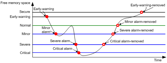
To ensure correct operation and improve memory efficiency, the device monitors the amount of free memory space in real time. If the amount of free memory space reaches the minor, severe, or critical alarm threshold, the system issues an alarm to affected service modules and processes.
The early warning feature warns you of an approaching insufficient-memory condition.
As shown in Table 1 and Figure 2, the device supports the following free-memory thresholds:
· Sufficient-memory threshold.
· Early-warning threshold.
· Normal state threshold.
· Minor alarm threshold.
· Severe alarm threshold.
· Critical alarm threshold.
Table 1 Memory alarm notifications and memory alarm-removed notifications
|
Notification |
Triggering condition |
Remarks |
|
Early-warning notification |
The amount of free memory space decreases below the early-warning threshold. |
After generating and sending an early-warning notification, the system does not generate and send any additional early-warning notifications until the early warning is removed. |
|
Minor alarm notification |
The amount of free memory space decreases below the minor alarm threshold. |
After generating and sending a minor alarm notification, the system does not generate and send any additional minor alarm notifications until the minor alarm is removed. |
|
Severe alarm notification |
The amount of free memory space decreases below the severe alarm threshold. |
After generating and sending a severe alarm notification, the system does not generate and send any additional severe alarm notifications until the severe alarm is removed. |
|
Critical alarm notification |
The amount of free memory space decreases below the critical alarm threshold. |
After generating and sending a critical alarm notification, the system does not generate and send any additional critical alarm notifications until the critical alarm is removed. |
|
Critical alarm-removed notification |
The amount of free memory space increases above the severe alarm threshold. |
N/A |
|
Severe alarm-removed notification |
The amount of free memory space increases above the minor alarm threshold. |
N/A |
|
Minor alarm-removed notification |
The amount of free memory space increases above the normal state threshold. |
N/A |
|
Early-warning-removed notification |
The amount of free memory space increases above the sufficient-memory threshold. |
N/A |
Figure 2 Memory alarm notifications and alarm-removed notifications
Restrictions and guidelines
If a memory alarm occurs, delete unused configuration items or disable some features to increase the free memory space. Because the memory space is insufficient, some configuration items might not be able to be deleted.
The VSR virtual routers do not support setting alarm thresholds in percentages.
Examples
# Set the minor, severe, and critical free-memory alarm thresholds to 20%, 10%, 5%, respectively. Set the normal state threshold to 20%.
<Sysname> system-view
[Sysname] memory-threshold ratio minor 20 severe 10 critical 5 normal 20
Configuration encryption
Hardening recommendations
To protect the startup configuration file, use configuration encryption. This feature enables the device to encrypt a startup configuration file automatically when it saves the running configuration to the file. All devices running Comware 7 software use the same private key or public key to encrypt configuration files.
Any devices running Comware 7 software can decrypt the encrypted configuration files. To prevent an encrypted file from being decoded by unauthorized users, make sure the file is accessible only to authorized users.
Restrictions and guidelines
You cannot use the more command or display commands to view the contents of an encrypted configuration file. However, you can use the display saved-configuration command to display the contents of the encrypted next-startup configuration file.
Examples
# Enable the public-key method for configuration encryption.
<Sysname> system-view
[Sysname] configuration encrypt public-key
# Enable the private-key method for configuration encryption.
<Sysname> system-view
[Sysname] configuration encrypt private-key
Security logs
Hardening recommendations
Security logs are very important for locating and troubleshooting network problems. Generally, security logs are output together with other logs. It is difficult to identify security logs among all logs.
To resolve this issue, you can configure the device to save security logs to the security log file. After you configure this feature, the system encapsulates security-related information as both standard system logs and security logs. The standard system logs are sent to console, monitor terminal, log buffer, log host, or other destinations as configured. The security logs are sent only to the security log file.
Restrictions and guidelines
To save security logs to the security log file, configure the following features:
· Enable saving security logs to the security file.
· Set the interval at which security logs are sent to the security log file.
· Set the maximum size of the security log file.
· Set an alarm threshold for the security log file usage ratio.
To manage the security log file, you must have the security-audit user role. This user role has permissions only to security log file management operations, including the following:
· Change the directory of the security log file.
· Manually save the security logs in the security log file buffer to the security log file.
Examples
· Save security logs to the security log file:
# Enable saving security logs to the security log file.
<Sysname> system-view
[Sysname] info-center security-logfile enable
# Set the security log file saving interval to 600 seconds.
[Sysname] info-center security-logfile frequency 600
# Set the maximum size to 2 MB for the security log file.
[Sysname] info-center security-logfile size-quota 2
· Manage the security log file:
# Log in to the device with the security-audit user role.
# Set the security log file directory to flash:/test.
<Sysname> mkdir test
Creating directory flash:/test... Done.
<Sysname> system-view
[Sysname] info-center security-logfile directory flash:/test
[Sysname] quit
# Manually save the security logs in the security log file buffer to the security log file.
<Sysname> security-logfile save
The contents in the security log file buffer have been saved to the file flash:/seclog/seclog.log.
VXLAN
Securing MAC address learning
Security threats
In a VXLAN network, VTEPs might learn incorrect remote MAC addresses from the forged VXLAN packets sent by attackers.
Hardening recommendations
To secure MAC address learning, you can disable remote-MAC address learning to prevent the device from learning incorrect remote MAC addresses. You can manually add static remote-MAC address entries or configure the device to learn remote MAC addresses from EVPN MAC/IP advertisement routes.
Examples
# Disable remote-MAC address learning.
<Sysname> system-view
[Sysname] vxlan tunnel mac-learning disable
Securing ARP learning
Security threats
If attackers send spoofed or malformed ARP or ND packets in an EVPN VXLAN network, VTEPs and gateways will learn incorrect ARP or ND entries and cannot forward traffic correctly.
Hardening recommendations
To secure ARP or ND learning, you can disable remote ARP or ND learning for VTEPs and gateways to learn ARP or ND information from EVPN MAC/IP advertisement routes.
Restrictions and guidelines
The hardening recommendations only apply to EVPN VXLAN networks.
Examples
# Disable remote ARP learning for VXLANs.
<Sysname> system-view
[Sysname] vxlan tunnel arp-learning disable
Confining traffic flooding
Hardware and feature compatibility
|
Hardware |
Confining traffic flooding compatibility |
|
SR6600 router series SR6600-X router series |
Yes |
|
MSR router series |
Yes |
|
VSR virtual routers |
No |
Security threats
In a VXLAN network, a VTEP floods broadcast, unknown unicast, and unknown multicast frames received from the local site to the following interfaces in the frame's VXLAN:
· All site-facing interfaces except for the incoming interface.
· All VXLAN tunnel interfaces.
When receiving broadcast, unknown unicast, and unknown multicast frames on VXLAN tunnel interfaces, the device floods the frames to all site-facing interfaces in the frames' VXLAN.
Hardening recommendations
To confine a kind of flood traffic, disable flooding for that kind of traffic on the VSI bound to the VXLAN.
Examples
# Disable flooding of local broadcast traffic to remote sites for VSI vsi1.
<Sysname> system-view
[Sysname] vsi vsi1
[Sysname-vsi-vsi1] flooding disable broadcast
# Disable flooding unknown unicast traffic received from an AC or VXLAN tunnel interface to any other ACs and VXLAN tunnel interfaces of VSI vsi1.
<Sysname> system-view
[Sysname] vsi vsi1
[Sysname-vsi-vsi1] flooding disable unknown-unicast all-direction
Hardening the control plane
Layer 2 protocols
Securing spanning tree networks
Hardware and feature compatibility
|
Hardware |
Spanning tree compatibility |
|
SR6600 router series SR6600-X router series |
Yes |
|
MSR router series |
Yes |
|
VSR virtual routers |
No |
Security threats
· BPDU attack
Access ports can directly connect to user terminals (such as PCs) or file servers. The access ports are configured as edge ports to allow rapid transition. When these ports receive configuration BPDUs, the system automatically sets the ports as non-edge ports and starts a new spanning tree calculation process. This causes a change of network topology. Under normal conditions, these ports should not receive configuration BPDUs. However, if a malicious user uses configuration BPDUs to attack the devices, the network will become unstable.
· Root bridge attack
Due to possible configuration errors or malicious attacks in the network, the legal root bridge might receive a configuration BPDU with a higher priority. Another device supersedes the current legal root bridge, which causes an undesired change of the network topology. The traffic that should go over high-speed links is switched to low-speed links, resulting in network congestion.
· TC-BPDU attack
If an attacker uses TC-BPDUs to attack the device, the device will receive a large number of TC-BPDUs within a short time. Then, the device is busy with forwarding address entry flushing. This affects network stability.
Hardening recommendations
To secure spanning tree networks, you can use the following features:
· BPDU guard
The BPDU guard feature protects the system against BPDU attacks.
· Root guard
The root guard feature keeps the designated role of a port on the root bridge to prevent frequent root bridge changes.
· TC-BPDU guard
TC-BPDU guard allows you to set the maximum number of immediate forwarding address entry flushes performed within 10 seconds after the device receives the first TC-BPDU. For TC-BPDUs received in excess of the limit, the device performs a forwarding address entry flush when the time period expires. This prevents frequent flushing of forwarding address entries.
Examples
· Configure BPDU guard.
# Enable BPDU guard globally.
<Sysname> system-view
[Sysname] stp bpdu-protection
· Enable root guard on an interface.
<Sysname> system-view
[Sysname] interface gigabitethernet 1/0/1
[Sysname-GigabitEthernet1/0/1] stp root-protection
· Set the maximum number of forwarding address entry flushes that the device can perform every 10 seconds.
<Sysname> system-view
[Sysname] stp tc-protection threshold 10
ARP attack protection
Enabling dynamic ARP entry check
Security threats
The sender MAC address of valid ARP packets is a unicast address. An attacker can forge ARP packets in which the sender MAC addresses are multicast addresses. If the gateway learns ARP entries for the multicast addresses and then forwards packets based on the ARP entries, the network resources will be heavily occupied.
Hardening recommendations
To avoid such a threat, enable the dynamic ARP entry check feature.
This feature prevents the device from learning dynamic ARP entries for multicast MAC addresses. Additionally, you cannot manually add static ARP entries for multicast MAC addresses.
Examples
# Enable dynamic ARP entry check.
<Sysname> system-view
[Sysname] arp check enable
Preventing ARP flooding
Configuring unresolvable IP attack protection
Security threats
If a device receives a large number of unresolvable IP packets from a host, the following threats occur:
· The device sends a large number of ARP requests, overloading the target subnets.
· The device keeps trying to resolve the destination IP addresses, overloading its CPU.
Hardening recommendations
To protect the device from such IP attacks, you can configure the following features:
· ARP source suppression—Stops resolving packets from an IP address if the number of unresolvable IP packets from the IP address exceeds the upper limit within 5 seconds. The device continues ARP resolution when the interval elapses. This feature is applicable if the attack packets have the same source addresses.
· ARP blackhole routing—Creates a blackhole route destined for an unresolved IP address. The device drops all matching packets until the blackhole route is deleted. A blackhole route is deleted when its aging timer is reached or the route becomes reachable.
After a blackhole route is created for an unresolved IP address, the device immediately starts the first ARP blackhole route probe by sending an ARP request. If the resolution fails, the device continues probing according to the probe settings. If the IP address resolution succeeds in a probe, the device converts the blackhole route to a normal route. If an ARP blackhole route ages out before the device finishes all probes, the device deletes the blackhole route and does not perform the remaining probes.
This feature is applicable regardless of whether the attack packets have the same source addresses.
Examples
· # Enable the ARP source suppression, and set the maximum number to 100 for unresolvable packets that can be processed per source IP address within 5 seconds.
<Sysname> system-view
[Sysname] arp source-suppression enable
[Sysname] arp source-suppression limit 100
· # Enable ARP blackhole routing, set the number of ARP blackhole route probes to 5 for each unresolved IP address, and set the probe interval to 3 seconds.
<Sysname> system-view
[Sysname] arp resolving-route enable
[Sysname] arp resolving-route probe-count 5
[Sysname] arp resolving-route probe-interval 3
Configuring source MAC-based ARP attack detection
Hardware and feature compatibility
|
Hardware |
Source MAC-based ARP attack detection compatibility |
|
SR6600 router series SR6600-X router series |
No |
|
MSR router series |
Yes |
|
VSR virtual routers |
No |
Security threats
If the device receives a large number of ARP packets from the same MAC address, resource exhaustion will occur and the device will fail to learn new ARP entries.
Hardening recommendations
To avoid such a threat, enable the source MAC-based ARP attack detection feature.
This feature enables the device to count the number of ARP packets delivered to the CPU. If the number of packets from the same MAC address within 5 seconds exceeds a threshold, the device generates an ARP attack entry for the MAC address. If the ARP logging feature is enabled, the device handles the attack by using either of the following methods before the ARP attack entry ages out:
· Monitor—Only generates log messages.
· Filter—Generates log messages and filters out subsequent ARP packets from the MAC address.
Restrictions and guidelines
When you change the handling method from monitor to filter, the configuration takes effect immediately. When you change the handling method from filter to monitor, the device continues filtering packets that match existing attack entries.
You can exclude the MAC addresses of the gateways and servers from this detection. The device does not inspect ARP packets from those excluded devices even if they send a large number of ARP packets.
Examples
# Enable source MAC-based ARP attack detection, and specify the handling method as filter.
<Sysname> system-view
[Sysname] arp source-mac filter
To enable source MAC-based ARP attack detection and specify the monitor handling method, use the arp source-mac monitor command.
# Set the threshold for source MAC-based ARP attack detection to 30.
[Sysname] arp source-mac threshold 30
# Set the aging timer for ARP attack entries to 60 seconds.
[Sysname] arp source-mac aging-time 60
# Exclude MAC address 001e-1200-0213 from source MAC-based ARP attack detection.
[Sysname] arp source-mac exclude-mac 001e-1200-0213
# Enable logging for source MAC-based ARP attack detection.
[Sysname] arp source-mac log enable
Configuring ARP packet rate limit
Hardware and feature compatibility
|
Hardware |
ARP packet rate limit compatibility |
|
SR6600 router series SR6600-X router series |
Yes |
|
MSR router series |
No |
|
VSR virtual routers |
No |
Security threats
Processing excessive ARP packets will cause entry resource exhaustion and will make the device malfunction or even crash.
Hardening recommendations
To solve this problem, configure ARP packet rate limit on an interface. When the receiving rate of ARP packets on the interface exceeds the rate limit, new incoming packets are discarded.
You can also enable sending notifications to the SNMP module or enable logging for ARP packet rate limit.
· If notification sending is enabled, the device sends the highest threshold-crossed ARP packet rate within the sending interval in a notification to the SNMP module. You must use the snmp-agent target-host command to set the notification type and target host. For more information about notifications, see SNMP commands in Network Management and Monitoring Command Reference.
· If logging for ARP packet rate limit is enabled, the device sends the highest threshold-crossed ARP packet rate within the sending interval in a log message to the information center. You can configure the information center module to set the log output rules. For more information about information center, see Network Management and Monitoring Configuration Guide.
Examples
# Enable SNMP notifications for ARP packet rate limit.
<Sysname> system-view
[Sysname] snmp-agent trap enable arp rate-limit
# Enable logging for ARP packet rate limit.
[Sysname] arp rate-limit log enable
# Set the notification and log message sending interval to 120 seconds.
[Sysname] arp rate-limit log interval 120
# Enable the ARP packet rate limit feature on GigabitEthernet 1/0/1, and set the maximum ARP packet rate to 50 pps.
[Sysname] interface gigabitethernet 1/0/1
[Sysname-GigabitEthernet1/0/1] arp rate-limit 50
Preventing ARP spoofing attacks
Security threats
An attacker may launch user spoofing attack or gateway spoofing attack.
· User spoofing attack—If an attacker sends a falsified ARP packet that deceives the gateway into adding a false IP-to-MAC address binding for a valid client, the client fails to receive packets from the gateway.
· Gateway spoofing attack—If an attacker sends a falsified ARP packet that deceives valid clients into adding a false IP-to-MAC binding for the gateway, the clients fail to access the gateway.
Enabling IP conflict notification
Hardening recommendations
Use the IP conflict notification feature to prevent gateway spoofing attacks.
This feature enables the device to detect and record user IP address conflicts. A conflict occurs if an incoming non-gratuitous ARP packet has the same sender IP address as an existing ARP entry but a different sender MAC address. The device generates a user IP address conflict record, logs the conflict, and sends the log to the information center.
Examples
# Enable IP conflict notification.
<Sysname> system-view
[Sysname] arp ip-conflict log prompt
Enabling ARP packet source MAC consistency check
Hardening recommendations
The ARP packet source MAC consistency check feature filters out ARP packets whose source MAC address in the Ethernet header is different from the sender MAC address in the message body. This feature ensures that the device learns correct ARP entries.
Examples
# Enable ARP packet source MAC consistency check.
<Sysname> system-view
[Sysname] arp valid-check enable
Configuring ARP active acknowledgment
Hardening recommendations
Use the ARP active acknowledgment feature to prevent user spoofing attacks.
This feature enables the device to perform validity checks before creating an ARP entry to prevent the device from generating incorrect ARP entries.
The strict mode enables the device to perform more strict validity checks as follows:
· Upon receiving an ARP request destined for the device, the device sends an ARP reply but does not create an ARP entry.
· Upon receiving an ARP reply, the device determines whether it has resolved the sender IP address:
¡ If yes, the device performs active acknowledgment. When the ARP reply is verified as valid, the gateway creates an ARP entry.
¡ If no, the device discards the packet.
Examples
# Enable strict ARP active acknowledgment in mode.
<Sysname> system-view
[Sysname] arp active-ack strict enable
Configuring authorized ARP
Hardening recommendations
Use the authorized ARP feature to prevent user spoofing attacks and to allow only authorized clients to access network resources.
This feature enables the device to generate authorized ARP entries based on the DHCP clients' address leases on the DHCP server or dynamic client entries on the DHCP relay agent. For more information about DHCP server and DHCP relay agent, see Layer 3—IP Services Configuration Guide.
Examples
# Enable authorized ARP on GigabitEthernet 1/0/1.
<Sysname> system-view
[Sysname] interface gigabitethernet 1/0/1
[Sysname-GigabitEthernet1/0/1] arp authorized enable
Configuring ARP attack detection
Hardware and feature compatibility
|
Hardware |
ARP attack detection compatibility |
|
SR6600 router series SR6600-X router series |
Yes |
|
MSR router series |
Yes |
|
VSR virtual routers |
No |
Hardening recommendations
· User validity check—This feature enables the device to perform user validity check on ARP untrusted interface. Upon receiving an ARP request, the device compares the sender IP and sender MAC in the ARP packet with the matching criteria in the following items:
¡ User validity check rules.
¡ Static IP source guard bindings.
¡ 802.1X security entries.
¡ DHCP snooping entries.
If a match is found, the device forwards the ARP packet. If no match is found, the device discards the ARP packet.
· ARP packet validity check—This feature enables the device to perform ARP packet validity check on ARP untrusted interface. You can configure the device to check the following items in ARP packets:
¡ Sender MAC address—Checks whether the sender MAC address in the message body is identical to the source MAC address in the Ethernet header. If they are identical, the packet is forwarded. Otherwise, the packet is discarded.
¡ Target MAC address—Checks the target MAC address of ARP replies. If the target MAC address is all-zero, all-one, or inconsistent with the destination MAC address in the Ethernet header, the packet is considered invalid and discarded.
¡ Sender and target IP addresses—Checks the sender and target IP addresses of ARP replies, and the sender IP address of ARP requests. All-one or multicast IP addresses are considered invalid and the corresponding packets are discarded.
· ARP restricted forwarding—This feature controls the forwarding of ARP packets that are received on untrusted interfaces and have passed user validity check as follows:
¡ If the packets are ARP requests, they are forwarded through the trusted interface.
¡ If the packets are ARP replies, they are forwarded according to their destination MAC address. If no match is found in the MAC address table, they are forwarded through the trusted interface.
These features does not affect ARP trusted interfaces.
Examples
· # Configure a user validity check rule numbered 0. This rule is used to guide the device to forward only ARP packets of which the source IP address is 10.1.1.1 with subnet mask 255.255.0.0 and the source MAC address is 0001-0203-0405 with subnet mask ffff-ffff-0000.
<Sysname> system-view
[Sysname] arp detection rule 0 permit ip 10.1.1.1 255.255.0.0 mac 0001-0203-0405 ffff-ffff-0000
# Enable ARP attack detection in VLAN 10.
[Sysname] vlan 10
[Sysname-vlan10] arp detection enable
[Sysname-vlan10] quit
# Configure GigabitEthernet 1/0/1 as an ARP trusted interface.
[Sysname] interface gigabitethernet 1/0/1
[Sysname-GigabitEthernet1/0/1] arp detection trust
· # Enable ARP packet validity check by checking the target MAC addresses and IP addresses of ARP packets.
<Sysname> system-view
[Sysname] arp detection validate dst-mac ip src-mac
# Enable ARP attack detection in VLAN 10.
[Sysname] vlan 10
[Sysname-vlan10] arp detection enable
[Sysname-vlan10] quit
# Configure GigabitEthernet 1/0/1 as an ARP trusted interface.
[Sysname] interface gigabitethernet 1/0/1
[Sysname-GigabitEthernet1/0/1] arp detection trust
· # Enable ARP restricted forwarding in VLAN 2.
<Sysname> system-view
[Sysname] vlan 2
[Sysname-vlan2] arp restricted-forwarding enable
Configuring ARP scanning and fixed ARP
Hardware and feature compatibility
|
Hardware |
ARP scanning and fixed ARP compatibility |
|
SR6600 router series SR6600-X router series |
No |
|
MSR router series |
Yes |
|
VSR virtual routers |
Yes |
Hardening recommendations
ARP scanning is typically used together with the fixed ARP feature in small-scale and stable networks.
ARP scanning automatically creates ARP entries for devices in an address range. The device performs ARP scanning in the following steps:
1. Sends ARP requests for each IP address in the address range.
2. Obtains their MAC addresses through received ARP replies.
3. Creates dynamic ARP entries.
Fixed ARP converts existing dynamic ARP entries (including those generated through ARP scanning) to static ARP entries. These static ARP entries are of the same attributes as the ARP entries that are manually configured. This feature prevents ARP entries from being modified by attackers.
Restrictions and guidelines
You can set the ARP packet sending rate if the scanning range has a large number of IP addresses. This setting can avoid high CPU usage and heavy network load caused by a burst of ARP traffic.
Due to the limit on the total number of static ARP entries, some dynamic ARP entries might fail the conversion.
Examples
# Start an ARP scanning on GigabitEthernet 1/0/1.
<Sysname> system-view
[Sysname] interface gigabitethernet 1/0/1
[Sysname-GigabitEthernet1/0/1] arp scan
[Sysname-GigabitEthernet1/0/1] quit
# Convert existing dynamic ARP entries to static ARP entries.
[Sysname] arp fixup
Configuring ARP gateway protection
Hardware and feature compatibility
|
Hardware |
ARP gateway protection compatibility |
|
SR6600 router series SR6600-X router series |
No |
|
MSR router series |
Yes |
|
VSR virtual routers |
No |
Hardening recommendations
To prevent gateway spoofing attacks, configure the ARP gateway protection feature on interfaces that are not connected with a gateway.
When an interface enabled with this feature receives an ARP packet, it checks whether the sender IP address in the packet is consistent with that of any protected gateway. If yes, it discards the packet. If not, it handles the packet correctly.
Restrictions and guidelines
Do not configure both ARP gateway protection and ARP filtering on an interface.
Examples
# Enable ARP gateway protection for the gateway at 1.1.1.1 on GigabitEthernet 1/0/1.
<Sysname> system-view
[Sysname] interface gigabitethernet 1/0/1
[Sysname-GigabitEthernet1/0/1] arp filter source 1.1.1.1
Configuring ARP filtering
Hardware and feature compatibility
|
Hardware |
ARP filtering compatibility |
|
SR6600 router series SR6600-X router series |
Yes |
|
MSR router series |
No |
|
VSR virtual routers |
No |
Hardening recommendations
To prevent gateway spoofing and user spoofing attacks, enable the ARP filtering feature.
An interface enabled with this feature checks the sender IP and MAC addresses in a received ARP packet against permitted entries. If a match is found, the packet is handled correctly. If not, the packet is discarded.
Restrictions and guidelines
Do not configure both ARP gateway protection and ARP filtering on an interface.
Examples
# Enable ARP filtering and configure an ARP permitted entry on GigabitEthernet 1/0/1.
<Sysname> system-view
[Sysname] interface gigabitethernet 1/0/1
[Sysname-GigabitEthernet1/0/1] arp filter binding 1.1.1.1 0e10-0213-1023
ND attack defense
Source MAC-based ND attack detection
Security threats
When the device receives excessive ND attack packets with fixed MAC addresses, it creates ND entries for them and cannot learn valid ND entries.
Hardening recommendations
To protect the device against excessive ND attack packets with fixed MAC addresses, use the source MAC-based ND attack detection. This feature checks the number of ND messages delivered to the CPU. If the number of messages from the same MAC address within the check interval exceeds the threshold, the device generates an ND attack entry for the MAC address. The processing of the ND messages sent from the MAC address in this entry depends on the detection mode. With ND logging enabled, source MAC-based ND attack detection processes the messages as follows:
· Filter mode—Filters out subsequent ND messages sent from the MAC address, and generates log messages.
· Monitor mode—Only generates log messages.
During the ND attack defense period, the device monitors the number of dropped packets in an entry within the aging time:
· If the number of dropped packets is higher than or equal to a calculated value, the device resets the aging time for the entry when the entry ages out.
· If the number of dropped packets is lower than the calculated value, the system deletes the entry when the entry ages out and marks MAC address in the entry as a common MAC address.
Restrictions and guidelines
When you change the detection mode from monitor to filter, the filter mode takes effect immediately. When you change the detection mode from filter to monitor, the device continues filtering ND messages that match existing attack entries.
You can exclude certain MAC addresses from source MAC-based ND attack detection on gateways and servers that might receive large numbers of ND messages. Source MAC-based ND attack detection does not drop ND messages sent from the excluded MAC addresses even if it detects attacks launched from these MAC addresses. Please exclude MAC addresses with caution and make sure no attack packets are sent from these MAC addresses.
Examples
# Enable source MAC-based ND attack detection and set the detection mode to monitor.
<Sysname> system-view
[Sysname] ipv6 nd source-mac monitor
To set the filter mode, execute the ipv6 nd source-mac filter command.
# Set the check interval to 30 seconds for source MAC-based ND attack detection.
[Sysname] ipv6 nd source-mac check-interval 30
# Set the threshold to 100 for source MAC-based ND attack detection.
[Sysname] ipv6 nd source-mac threshold 100
# Set the aging time to 100 seconds for source MAC-based ND attack detection entries.
[Sysname] ipv6 nd source-mac aging-time 100
# Exclude the MAC address 001e-1200-0213 from source MAC-based ND attack detection.
[Sysname] ipv6 nd source-mac exclude-mac 001e-1200-0213
# Enable ND logging.
[Sysname] ipv6 nd check log enable
Access services
Securing PPP
Configuring PPP authentication
Hardening recommendations
To secure PPP, you can configure PPP authentication. By cooperating with AAA, PPP supports the following authentication methods:
· PAP—PAP is a two-way handshake authentication protocol using the username and password.
PAP sends username/password pairs in plain text over the network. If authentication packets are intercepted in transit, network security might be threatened. For this reason, it is suitable only for low-security environments.
· CHAP—CHAP is a three-way handshake authentication protocol.
CHAP transmits usernames but not passwords over the network. It transmits the result calculated from the password and random packet ID by using the MD5 algorithm. It is more secure than PAP. The authenticator may or may not be configured with a username. As a best practice, configure a username for the authenticator, which makes it easier for the peer to verify the identity of the authenticator.
· MS-CHAP—MS-CHAP is a three-way handshake authentication protocol.
MS-CHAP differs from CHAP as follows:
¡ MS-CHAP uses CHAP Algorithm 0x80.
¡ MS-CHAP provides authentication retry. If the peer fails authentication, it is allowed to retransmit authentication information to the authenticator for reauthentication. The authenticator allows a peer to retransmit a maximum of three times.
· MS-CHAP-V2—MS-CHAP-V2 is a three-way handshake authentication protocol.
MS-CHAP-V2 differs from CHAP as follows:
¡ MS-CHAP-V2 uses CHAP Algorithm 0x81.
¡ MS-CHAP-V2 provides two-way authentication by piggybacking a peer challenge on the Response packet and an authenticator response on the Acknowledge packet.
¡ MS-CHAP-V2 supports authentication retry. If the peer fails authentication, it is allowed to retransmit authentication information to the authenticator for reauthentication. The authenticator allows a peer to retransmit a maximum of three times.
¡ MS-CHAP-V2 supports password change. If the peer fails authentication because of an expired password, it will send the new password entered by the user to the authenticator for reauthentication.
Restrictions and guidelines
For local AAA authentication, the username and password of the peer must be configured on the authenticator. For remote AAA authentication, the username and password of the peer must be configured on the remote AAA server.
· PAP
The username and password configured for the peer must be the same as those configured on the peer by using the ppp pap local-user command.
· CHAP authentication (authenticator name is configured)
When you configure the authenticator, the username and password configured for the peer must meet the following requirements:
¡ The username configured for the peer must be the same as that configured on the peer by using the ppp chap user command.
¡ The passwords configured for the authenticator and peer must be the same.
When you configure the peer, the username and password configured for the authenticator must meet the following requirements:
¡ The username configured for the authenticator must be the same as that configured on the authenticator by using the ppp chap user command.
¡ The passwords configured for the authenticator and peer must be the same.
The peer does not support the CHAP authentication password configured by using the ppp chap password command. CHAP authentication (authenticator name is configured) will apply even if the authentication name is configured.
· CHAP authentication (authenticator name is not configured)
The username and password configured for the peer must meet the following requirements:
¡ The username configured for the peer must be the same as that configured on the peer by using the ppp chap user command.
¡ The password configured for the peer must be the same as that configured on the peer by using the ppp chap password command.
· MS-CHAP or MS-CHAP-V2 authentication
The device can only act as an authenticator for MS-CHAP or MS-CHAP-V2 authentication.
L2TP supports only MS-CHAP authentication.
MS-CHAP-V2 authentication supports password change only when using RADIUS.
As a best practice, do not set the authentication method for PPP users to none when MS-CHAP-V2 authentication is used.
The username and password of the peer configured on the authenticator or remote AAA server must be the same as those configured on the peer.
If authentication name is configured, the username configured for the authenticator on the peer must be the same as that configured on the authenticator by using the ppp chap user command.
Examples
· PAP authentication
¡ Configuring the authenticator
# Configure the authenticator to authenticate the peer by using PAP.
<Sysname> system-view
[Sysname] interface virtual-template 1
[Sysname-Virtual-Template1] ppp authentication-mode pap domain system
# Configure local or remote AAA authentication.
For more information about AAA authentication, see Security Configuration Guide.
¡ Configuring the peer
# Configure the PAP username and password sent from the peer to the authenticator when the peer is authenticated by the authenticator by using PAP.
<Sysname> system-view
[Sysname] interface virtual-template 1
[Sysname-Virtual-Template1] ppp pap local-user userb password simple passb
· Configuring CHAP authentication (authenticator name is configured)
¡ Configuring the authenticator
# Configure the authenticator to authenticate the peer by using CHAP.
<Sysname> system-view
[Sysname] interface virtual-template 1
[Sysname-Virtual-Template1] ppp authentication-mode chap domain system
# Configure a username for the CHAP authenticator.
[Sysname-Virtual-Template1] ppp chap user usera
# Configure local or remote AAA authentication.
For more information about AAA authentication, see Security Configuration Guide.
¡ Configuring the peer
# Configure a username for the CHAP peer.
<Sysname> system-view
[Sysname] interface virtual-template 1
[Sysname-Virtual-Template1] ppp chap user userb
# Configure local or remote AAA authentication.
For more information about AAA authentication, see Security Configuration Guide.
· Configuring CHAP authentication (authenticator name is not configured)
¡ Configuring the authenticator
# Configure the authenticator to authenticate the peer by using CHAP.
<Sysname> system-view
[Sysname] interface virtual-template 1
[Sysname-Virtual-Template1] ppp authentication-mode chap domain system
# Configure local or remote AAA authentication.
For more information about AAA authentication, see Security Configuration Guide.
¡ Configuring the peer
# Configure a username for the CHAP peer.
<Sysname> system-view
[Sysname] interface virtual-template 1
[Sysname Virtual-Template1] ppp chap user userb
# Set the CHAP authentication password.
[Sysname-Virtual-Template1] ppp chap password simple hello&358
· Configuring MS-CHAP or MS-CHAP-V2 authentication (authenticator name is configured)
¡ Configuring the peer
# Configure the authenticator to authenticate the peer by using MS-CHAP or MS-CHAP-V2.
<Sysname> system-view
[Sysname] interface virtual-template 1
[Sysname-Virtual-Template1] ppp authentication-mode ms-chap domain system
[Sysname-Virtual-Template1] ppp authentication-mode ms-chap-v2 domain system
# Configure a username for the MS-CHAP or MS-CHAP-V2 authenticator.
[Sysname-Virtual-Template1] ppp chap user usera
# Configure local or remote AAA authentication.
For more information about AAA authentication, see Security Configuration Guide.
· Configuring MS-CHAP or MS-CHAP-V2 authentication (authenticator name is not configured)
¡ Configuring the peer
# Configure the authenticator to authenticate the peer by using MS-CHAP or MS-CHAP-V2.
<Sysname> system-view
[Sysname] interface virtual-template 1
[Sysname-Virtual-Template1] ppp authentication-mode ms-chap domain system
[Sysname-Virtual-Template1] ppp authentication-mode ms-chap-v2 domain system
# Configure local or remote AAA authentication.
For more information about AAA authentication, see Security Configuration Guide.
Enhancing management and control for PPP users
Hardware and feature compatibility
|
Hardware |
Compatibility with PPP user enhanced management and control |
|
SR6600 router series SR6600-X router series |
Yes |
|
MSR router series |
Yes |
|
VSR virtual routers |
No |
Security threats
In a PPP network, a user might user illegal IP addresses to access network resources.
Hardening recommendations
To avoid the security threats above, you can configure IP segment match for PPP users. This feature enables the local interface to check whether its IP address and the IP address of the remote interface are in the same network segment. If they are not, IPCP negotiation fails.
Examples
# Enable the IP segment match feature on Virtual-Template 1.
<Sysname> system-view
[Sysname] interface virtual-template 1
[Sysname-Virtual-Template1] ppp ipcp remote-address match
Securing PPPoE
Enhancing management and control for PPPoE users
Hardware and feature compatibility
|
Hardware |
Compatibility with PPPoE user enhanced management and control |
|
SR6600 router series SR6600-X router series |
No |
|
MSR router series |
Yes |
|
VSR virtual routers |
Yes |
Security threats
The following security threats exist in a PPP network:
· When a large number of users frequently come online and go offline, the device processing performance will be affected.
· A single user establishes a large number of PPPoE sessions, which will occupy too many session resources and cause other users to fail to come online.
Hardening recommendations
To avoid the security threats above, you can configure the following security features on the device to enhance management and control for PPPoE users:
· Limiting the rate at which a user creates PPPoE sessions
This feature limits the rate at which a user (identified by MAC address) can create PPPoE sessions on an interface. If the number of PPPoE requests within the monitoring time exceeds the configured threshold, the device discards the excessive requests, and outputs log messages. If the blocking time is set to 0, the device does not block any requests, and it only outputs log messages.
· Limiting the maximum number of PPPoE sessions
PPPoE can establish a session when none of the following limits are reached:
¡ Limit for a user on an interface.
¡ Limit for a VLAN on an interface.
¡ Limit on an interface.
¡ (Distributed devices in standalone mode.) (Distributed devices in IRF mode.) Limit on a card.
¡ (Centralized IRF devices.) Limit on an IRF member device.
¡ (Centralized devices.) Limit on a device.
The maximum number of PPPoE sessions on a device or on a card is also limited by the device specification. If the configured number is larger than the device specification, the device specification applies. The device specification varies by device model.
Restrictions and guidelines
· Maximum number of PPPoE sessions
PPPoE can establish a session when none of the limits are reached.
If the configured limit is smaller than the number of existing online sessions on the interface, the configuration succeeds. The configuration does not affect the existing online sessions. However, new sessions cannot be established on the interface.
The maximum number of PPPoE sessions supported by a device varies by license or device model.
(Centralized devices.)The maximum number of PPPoE sessions set for a device cannot be greater than the maximum number of PPPoE sessions supported by the device.
(Distributed devices.) (Centralized IRF devices.) The total maximum number of PPPoE sessions set for all cards or IRF member devices cannot be greater than the maximum number of PPPoE sessions supported by the device.
Examples
· Limiting the rate at which a user can create PPPoE sessions
# Limit the rate at which a user can create PPPoE sessions on GigabitEthernet 1/0/1.
<Sysname> system-view
[Sysname] interface gigabitethernet 1/0/1
[Sysname-GigabitEthernet1/0/1] pppoe-server throttle per-mac 100 80 10
· Setting the maximum number of PPPoE sessions
¡ Set the maximum number of PPPoE sessions for a user on an interface
# Set the maximum number of PPPoE sessions for a user on GigabitEthernet 1/0/1 to 50.
<Sysname> system-view
[Sysname] interface gigabitethernet 1/0/1
[Sysname-GigabitEthernet1/0/1] pppoe-server session-limit per-mac 50
¡ Setting the maximum number of PPPoE sessions on a VLAN
# Set the maximum number of PPPoE sessions for a VLAN on GigabitEthernet 1/0/1.1 to 50.
<Sysname> system-view
[Sysname] interface gigabitethernet 1/0/1.1
[Sysname-GigabitEthernet1/0/1.1] pppoe-server session-limit per-vlan 50
¡ Setting the maximum number of PPPoE sessions on an interface
# Set the maximum number of PPPoE sessions on GigabitEthernet 1/0/1 to 50.
<Sysname> system-view
[Sysname] interface gigabitethernet 1/0/1
[Sysname-GigabitEthernet1/0/1] pppoe-server session-limit 50
¡ Setting the maximum number of PPPoE sessions on a device
# (Centralized devices.) Set the maximum number of PPPoE sessions on a device to 3000.
<Sysname> system-view
[Sysname] pppoe-server session-limit total 3000
# (Distributed devices in standalone mode.) (Centralized IRF devices.) Set the maximum number of PPPoE sessions on slot 2 to 3000.
[Sysname] pppoe-server session-limit slot 2 total 3000
# (Distributed devices in IRF mode.) Set the maximum number of PPPoE sessions on slot 2 of IRF member device 1 to 3000.
[Sysname] pppoe-server session-limit chassis 1 slot 2 total 3000
Securing PPPoE protocol packets
Security threats
The following security threats exist in a PPPoE network:
· An illegal user initiates attacks through protocol packets to occupy a large number of system resources, and causes DoS on the device.
· When the device is being rebooted or upgrading the software, some users might fail to come online properly if the online requests from a large number of PPPoE users affects the CPU processing performance of the device.
Hardening recommendations
To avoid the security threats above, you can configure PADI/PADR packet check on the device to enhance security management for PPPoE protocol packets. When PADI/PADR packet check is enabled, upon receiving a PADI or a PADR packet from a PPPoE client, the PPPoE server compares its service name with the service-name tag field of the packet. The server accepts the session establishment request only if the field matches the service name.
Restrictions and guidelines
You can configure a maximum of 8 service names on an interface.
Examples
# Set the service name to pppoes for the PPPoE server on GigabitEthernet 1/0/1.
<Sysname> system-view
[Sysname] interface gigabitethernet 1/0/1
[Sysname-GigabitEthernet1/0/1] pppoe-server tag service-name pppoes
Securing L2TP
Configuring L2TP user authentication
Hardening recommendations
To secure L2TP, configure L2TP user authentication. By cooperating with AAA, L2TP provides the following security authentication methods for users:
· AAA authentication on an LAC
You can configure AAA authentication an LAC to authenticate the remote dialup users and initiate a tunneling request only for qualified users. A tunnel will not be established for unqualified users.
For local AAA authentication, create a local user and configure a password for each remote user on the LAC. For remote AAA authentication, configure the remote username and password of each user.
· AAA authentication on an LNS
After you configure AAA authentication on an LNS, the LNS can authenticate the usernames and passwords of remote access users. If a user passes AAA authentication, the user can communicate with the LNS to access the private network.
For local AAA authentication, create a local user and configure a password for each remote user on the LAC. For remote AAA authentication, configure the remote username and password of each user.
An LNS can be configured to authenticate a user that has passed authentication on the LAC to increase security. In this case, the user is authenticated once on the LAC and once on the LNS. An L2TP tunnel can be established only when both authentications succeed.
An LNS provides the following authentication methods in ascending order of priority:
¡ Proxy authentication—The LNS uses the LAC as an authentication proxy. The LAC sends the LNS all user authentication information from users and the authentication method configured on the LAC itself. The LNS then checks the user validity according to the received information and the locally configured authentication method.
¡ Mandatory CHAP authentication—The LNS uses CHAP authentication to reauthenticate users who have passed authentication on the LAC.
¡ LCP renegotiation—The LNS ignores the LAC proxy authentication information and performs a new round of LCP negotiation with the user.
Restrictions and guidelines
When you configure AAA authentication on the LNS, follow these restrictions and guidelines:
· The mandatory CHAP authentication and LCP renegotiation methods are effective only on NAS-initiated L2TP tunnels.
· If you configure both LCP renegotiation and mandatory CHAP authentication, the LNS uses LCP renegotiation.
· If you configure neither LCP renegotiation nor mandatory CHAP authentication, the LNS uses the LAC for proxy authentication.
· When you configure mandatory CHAP authentication, follow these restrictions and guidelines
¡ For mandatory CHAP authentication to take effect, you must also configure CHAP authentication for the PPP users on the VT interface of the LNS.
¡ For users that do not support a new round of authentication, as a best practice, do not configure this feature. Otherwise, the L2TP tunnels cannot be established because the users fail to pass CHAP authentication on the LNS.
· With mandatory LCP renegotiation enabled, if the corresponding VT interface is not configured with authentication, the LNS does not perform a new round of authentication for users. In this case, the users are authenticated only once on the LAC.
Examples
· Configuring AAA on an LAC
For more information about configuring AAA authentication, see Security Configuration Guide.
To enable AAA authentication on an LAC, you also need to configure PAP or CHAP authentication for PPP users on the user access interfaces. For information about configuring PAP or CHAP, see Layer 2—WAN Access Configuration Guide.
· Configuring AAA on an LNS
For more information about configuring AAA authentication, see Security Configuration Guide.
¡ Configuring mandatory LCP renegotiation
# Force an LNS to perform LCP negotiation with users.
<Sysname> system-view
[Sysname] l2tp-group 1 mode lns
[Sysname-l2tp1] mandatory-lcp
¡ Configuring mandatory CHAP authentication
# Force the LNS to perform CHAP authentication for users.
<Sysname> system-view
[Sysname] l2tp-group 1 mode lns
[Sysname-l2tp1] mandatory-chap
# Enter VT interface view and configure the interface to authentication PPP users by using CHAP.
For more information about VT interfaces, see Layer 2—WAN Access Configuration Guide.
Securing L2TP tunnel data
Security threats
The following security threats exist in an L2TP network:
· An illegal peer establishes a tunnel to the local end to get internal data of the local end.
· An illegal user gets the AVP data (for example, tunnel negotiation parameters, session negotiation parameters, and user authentication information) transferred in plaintext.
Hardening recommendations
To avoid the security threats above, you can configure the following security features on the device:
· L2TP tunnel authentication
Tunnel authentication allows the LAC and LNS to authenticate each other. Either the LAC or the LNS can initiate a tunnel authentication request. A tunnel can be established between them only when both authentications succeed. To ensure tunnel security, enable tunnel authentication.
· Transferring AVP data in hidden mode
L2TP uses Attribute Value Pairs (AVPs) to transmit tunnel negotiation parameters, session negotiation parameters, and user authentication information. Transferring AVP data in hidden mode can hide sensitive AVP data such as user passwords.
Restrictions and guidelines
· Configuring tunnel authentication
Modifying the tunnel authentication key does not affect the normal communication of current tunnels. The tunnel authentication key change takes effect at next tunnel establishment.
· Transferring AVP data in hidden mode
This configuration takes effect only when the tunnel authentication feature is enabled.
Examples
· Configuring tunnel authentication
# Enable L2TP tunnel authentication.
<Sysname> system-view
[Sysname] l2tp-group 1 mode lns
[Sysname-l2tp1] tunnel authentication
# Specify the tunnel authentication key as &569pass1.
[Sysname-l2tp1] tunnel password simple &569pass1
· Transferring AVP data in hidden mode
# Enable L2TP tunnel authentication.
<Sysname> system-view
[Sysname] l2tp-group 1 mode lac
[Sysname-l2tp1] tunnel authentication
# Specify the tunnel authentication key as &569pass1.
[Sysname-l2tp1] tunnel password simple &569pass1
# Enable transferring AVP data in hidden mode.
[Sysname-l2tp1] tunnel avp-hidden
Securing LAC/LNS device performance
Security threats
In an L2TP network, an LNS might encounter the following security threats:
· When a user comes online, the LNS creates a VA interface for the user to exchange data with the LAC. After the user goes offline, the VA interface must be deleted. Creating and deleting VA interfaces consumes certain system resources. When the device is attacked by a large number of users frequently coming online and going offline, the device processing capability will be insufficient, and a DoS attack occurs.
· When a large number of L2TP users come online, the device performance will be affected.
· When a large number of disordered packets are processed, the device performance will be affected.
· When the number of packets received on the local end exceeds the processing capability of the local end, some users might fail to come online.
Hardening recommendations
To avoid the security threats above, you can configure the following security features on the device to reduce the influence on the device performance and ensure L2TP users can come online stably:
· Configuring a VA pool
A VA pool contains a group of VA interfaces. You can configure a VA pool to improve the performance of establishing or terminating L2TP connections. The LNS selects a VA interface from the pool for a requesting user and releases the VA interface when the user goes offline. In this way, the L2TP tunnel establishment and termination rates are improved, and the influence on the device performance when a large number of users come online or go offline is reduced.
· Setting the receiving window size for L2TP
To enable the device to process a larger number of disordered packets, use this feature to enlarge the receiving window size for an L2TP tunnel.
The device uses a receiving window to reorder disordered packets based on packet sequence numbers.
If the sequence number of a packet is within the receiving window but does not equal the minimum value of the window, the device performs the following operations:
a. The device buffers the packet.
b. The minimum value and maximum value of the receiving window increment by one.
c. The device continues to check the next arriving packet.
If the sequence number of a packet equals the minimum value of the receiving window, the device performs the following operations:
a. The device processes the packet.
b. The minimum value and maximum value of the receiving window increment by one.
c. The device checks buffered packets for a packet with the sequence number equal to the new minimum value of the receiving window.
d. If no required packet is found, the device checks the next arriving packet.
If the sequence number of a packet is not within the receiving window, the device drops the packet.
· Setting the sending window size for L2TP
The packet processing capability of a peer end might mismatch the receiving window size of the peer end in some networks. For example, the actual packet processing capability of the peer end is 10, but the receiving window size of the peer end is 20. To ensure stable L2TP services, you can adjust the sending window size for the device to match the actual packet processing capability of the peer end.
Restrictions and guidelines
· Configuring a VA pool
A VT interface can be associated with only one VA pool. To change the capacity of a VA pool, delete the previous configuration and reconfigure the VA pool.
Creating or deleting a VA pool takes time. During the process of creating or deleting a VA pool, users can come online or go offline, but the VA pool does not take effect.
The system might create a VA pool that contains VA interfaces less than the specified number because of insufficient resources. To view the number of available VA interfaces and the current state of the VA pool, use the display l2tp va-pool command.
Create a VA pool with an appropriate capacity, because a VA pool occupies much system memory.
Deleting a VA pool does not log off the users who are using VA interfaces in the VA pool.
· Setting the receiving window size for L2TP
In the L2TP tunnel establishment process, the device uses the value specified in L2TP group view as the receiving window size. Changing the receiving window size after an L2TP tunnel is established does not affect the established L2TP tunnel.
· Setting the sending window size for L2TP
The sending window size set in L2TP group view is obtained in the L2TP tunnel establishment process.
¡ If the sending window size is 0, the device uses the default sending window size.
¡ If the sending window size is not 0, the device uses the specified value as the sending window size.
Changing the sending window size after an L2TP tunnel is established does not affect the established L2TP tunnel.
Examples
· Configuring a VA pool
# Create a VA pool with a capacity of 1000 VA interfaces for Virtual-template 2.
<Sysname> system-view
[Sysname] l2tp virtual-template 2 va-pool 1000
· Setting the receiving window size for L2TP
# Set the receiving window size for L2TP group 1 to 128.
<Sysname> system-view
[Sysname] l2tp-group 1 mode lac
[Sysname-l2tp1] tunnel window receive 128
· Setting the sending window size for L2TP
# Set the sending window size for L2TP group 1 to 128.
<Sysname> system-view
[Sysname] l2tp-group 1 mode lac
[Sysname-l2tp1] tunnel window send 128
Configuring 802.1X
802.1X quiet function
Hardware and feature compatibility
|
Hardware |
802.1X quiet compatibility |
|
SR6600 router series SR6600-X router series |
No |
|
MSR router series |
Yes |
|
VSR virtual routers |
No |
Security threats
The device authenticates clients that have failed 802.1X authentication immediately after they initiate a reauthentication. The device might be overwhelmed if it receives a large number of messages that contain incorrect authentication information (for example, incorrect username or password) in a short time.
Hardening recommendations
To protect the device against malicious 802.1X clients, enable the quiet timer. The quiet timer enables the device to wait a period of time before it processes any reauthentication request from a client that has failed 802.1X authentication.
Set the quiet timer depending on the network conditions.
· In a vulnerable network, set the quiet timer to a high value.
· In a high-performance network with quick authentication response, set the quiet timer to a low value.
Examples
# Enable the quiet timer and set the quiet timer to 100 seconds.
<Sysname> system-view
[Sysname] dot1x quiet-period
[Sysname] dot1x timer quiet-period 100
Online user handshake security
Security threats
Online 802.1X users can use illegal client software to bypass iNode security check, such as proxy detection and dual network interface cards (NICs) detection.
Hardening recommendations
Enable online user handshake security on a port to identify users that are using the iNode client to exchange handshake packets with the device. If a user fails the handshake security checking, the device sets the user to the offline state.
Restrictions and guidelines
To use the online user handshake security feature, you must enable the online user handshake feature.
The online user handshake security feature takes effect only on a network where the iNode client and IMC server are used.
Examples
# Enable online user handshake security on GigabitEthernet 1/0/1.
<Sysname> system-view
[Sysname] interface gigabitethernet 1/0/1
[Sysname-GigabitEthernet1/0/1] dot1x handshake
[Sysname-GigabitEthernet1/0/1] dot1x handshake secure
Configuring port security
The following compatibility matrix shows the support of the hardware for port security:
|
Hardware |
Port security compatibility |
|
SR6600 router series SR6600-X router series |
Yes |
|
MSR router series |
Yes |
|
VSR virtual routers |
No |
Port security combines and extends 802.1X and MAC authentication to provide MAC-based network access control. Use port security on a port if its attached network contains both 802.1X and MAC authentication users.
Port security provides the following security features:
· Need to know (NTK)—This feature prevents traffic interception by checking the destination MAC address in the outbound frames. The feature ensures that frames are sent only to the following hosts:
¡ Hosts that have passed authentication.
¡ Hosts whose MAC addresses have been learned or configured on the device.
· Intrusion protection—This feature checks the source MAC address in inbound frames for illegal frames, and takes a predefined action on each detected illegal frame. The action can be disabling the port temporarily, disabling the port permanently, or blocking frames from the illegal MAC address for a period set by the MAC block timer.
A frame is illegal if its source MAC address cannot be learned in a port security mode or it is from a client that has failed authentication.
· Port security modes—Port security supports the following categories of security modes:
¡ MAC learning control—Includes two modes: autoLearn and secure. MAC address learning is permitted on a port in autoLearn mode and disabled in secure mode.
¡ Authentication—Security modes in this category perform MAC authentication, 802.1X authentication, or a combination of these two authentication methods.
Upon receiving a frame, the port in a security mode searches the MAC address table for the source MAC address. If a match is found, the port forwards the frame. If no match is found, the port learns the MAC address or performs authentication, depending on the security mode. If the frame is illegal, the port takes the predefined NTK or intrusion protection action, or sends SNMP notifications. Outgoing frames are not restricted by port security's NTK action unless they trigger the NTK feature.
Table 2 describes how to use the port security modes in combination with the security features to fulfill your security purposes.
|
Purpose |
Security mode |
Features that can be triggered |
|
|
Turning off the port security feature |
noRestrictions (the default mode) In this mode, port security is disabled on the port and access to the port is not restricted. |
N/A |
|
|
Controlling MAC address learning |
autoLearn |
NTK/intrusion protection |
|
|
secure |
|||
|
Performing 802.1X authentication |
userLogin |
N/A |
|
|
userLoginSecure |
NTK/intrusion protection |
||
|
userLoginSecureExt |
|||
|
userLoginWithOUI |
|||
|
Performing MAC authentication |
macAddressWithRadius |
NTK/intrusion protection |
|
|
Performing a combination of MAC authentication and 802.1X authentication |
Or |
macAddressOrUserLoginSecure |
NTK/intrusion protection |
|
macAddressOrUserLoginSecureExt |
|||
|
Else |
macAddressElseUserLoginSecure |
||
|
macAddressElseUserLoginSecureExt |
|||
For more information about port security, see Security Configuration Guide.
Securing portal
Controlling portal user access
Hardware and feature compatibility
|
Hardware |
Compatibility with per-user redirection session limit |
Compatibility with portal safe-redirect |
Compatibility with blocking authentication failed portal users |
Compatibility with allowing only DHCP users to pass portal authentication |
|
SR6600 router series SR6600-X router series |
Yes |
Yes |
Yes |
Yes |
|
MSR router series |
No |
Yes |
No |
Yes |
|
VSR virtual routers |
No |
No |
No |
No |
Security threats
On a portal network, the following security threats might exist:
· If an attacker frequently initiates HTTP or HTTPS requests, the device needs to redirect a large number of HTTP or HTTPS requests, which causes resource insufficiency.
· If an attacker sends a large number of HTTP or HTTPS requests, the resources on the portal server exhaust, and the server cannot respond to authentication requests from valid users.
· An invalid user makes exhaustive password cracking attempts to guess the password of valid users.
· An invalid user accesses the network.
Hardening recommendations
To defense against the above security threats, configure the following features on the device:
· Portal HTTP and HTTPS attack defense
¡ Limiting the number of per-user redirection sessions—This feature limits the number of portal redirection sessions for a single user. If the HTTP or HTTPS redirection sessions for a user exceeds the limit, the device denies new redirection requests from the user.
¡ Portal safe-redirect—This feature filters HTTP and HTTPS requests by request method, browser type, and destination URL, and redirects only the permitted HTTP and HTTPS requests. This reduces the risk that the portal Web server cannot respond to HTTP and HTTPS requests because of overload.
· Blocking portal users that fail portal authentication—This feature blocks a portal user if the user consecutively fails authentication for the specified times within the failure detection period. All authentication requests from the user are dropped by the device till the blocking times out. The blocked portal user can perform portal authentication again when the blocking timeout time expires.
· Allowing only DHCP users to pass portal authentication—This feature allows only users with DHCP-assigned IP addresses to pass portal authentication. Users with static IP addresses cannot pass portal authentication to come online. This feature ensures that only users with valid IP addresses can access the network.
Restrictions and guidelines
The allowing only DHCP users to pass portal authentication feature takes effect only on a network where the access device also acts as the DHCP server.
In an IPv6 portal network, terminal device users might use temporary IPv6 addresses to access the network. To ensure that these IPv6 users can pass portal authentication when only users with DHCP-assigned IP addresses to pass portal authentication is enabled, disable the temporary IPv6 address feature on terminal devices.
Portal preauthentication users will not be blocked even though they consecutively fail authentication for the specified times within the failure detection period.
In wireless networks, the maximum number of portal redirection sessions for a single user takes effect only in centralized forwarding mode.
Examples
· Configure portal HTTP and HTTPS attack defense:
# Enable portal HTTP and HTTPS attack defense.
<Sysname> system-view
[Sysname] portal http-defense enable
# Set portal HTTP and HTTPS attack defense parameters: set the blocking timer to 5 minutes, the statistical interval to 2 minutes, and the blocking threshold to 200 packets.
[Sysname] portal http-defense block-timeout 5 statistics-interval 2 threshold 200
# Set the maximum number of destination IP addresses to 2000 for portal HTTP and HTTPS attack defense.
[Sysname] portal http-defense max-ip-number 2000
· Configure portal HTTP and HTTPS attack defense
¡ Limit the number of per-user redirection sessions:
# Set the maximum number of portal redirect sessions for a single user to 128.
<Sysname> system-view
[Sysname] portal redirect max-session per-user 128
¡ Configure portal safe-redirect:
# Enable portal safe-redirect.
<Sysname> system-view
[Sysname] portal safe-redirect enable
# Specify the GET request method for portal safe-redirect.
[Sysname] portal safe-redirect method get
# Specify browser types Chrome and Safari for portal safe-redirect.
[Sysname] portal safe-redirect user-agent Chrome
[Sysname] portal safe-redirect user-agent Safari
# Specify http://www.abc.com as a portal safe-redirect forbidden URL.
[Sysname] portal safe-redirect forbidden-url http://www.abc.com
# Specify .jpg as a portal safe-redirect forbidden filename extension.
[Sysname] portal safe-redirect forbidden-file .jpg
# Configure the default action as permit for portal safe-redirect.
[Sysname] portal safe-redirect default-action permit
# Specify http://www.abc.com as a portal safe-redirect permitted URL.
[Sysname] portal safe-redirect permit-url http://www.abc.com
· Block portal users that fail portal authentication:
# Configure the device to block a portal user if the user consecutively fails portal authentication twice within 100 minutes.
<Sysname> system-view
[Sysname] portal user-block failed-times 2 period 100
# Set the portal user blocking timeout time to 20 minutes.
[Sysname] portal user-block reactive 20
· Allow only DHCP users to pass portal authentication:
# Allow only users with DHCP-assigned IP addresses on GigabitEthernet 1/0/1 to pass portal authentication.
<Sysname> system-view
[Sysname] interface gigabitethernet 1/0/1
[Sysname-GigabitEthernet1/0/1] portal user-dhcp-only
Enabling validity check on wireless clients
Hardware and feature compatibility
|
Hardware |
Wireless client validity check compatibility |
|
SR6600 router series SR6600-X router series |
No |
|
MSR router series |
Yes |
|
VSR virtual routers |
No |
Hardening recommendations
In wireless networks where the AP forwards client traffic, the AC does not have ARP entries for clients. Therefore, the AC cannot use ARP entries to check the validity of portal clients. To ensure that valid users can perform portal authentication, you must enable wireless client validity check on the AC.
This feature enables the AC to validate a client by looking up the client information in the WLAN snooping table, DHCP snooping table, and ARP table. If the client information exists, the AC determines the client to be valid for portal authentication.
Examples
# Enable validity check on wireless clients.
<Sysname> system-view
[Sysname] portal host-check enable
Limiting the number of portal users
Hardware and feature compatibility
|
Hardware |
Portal user number limit compatibility |
|
SR6600 router series SR6600-X router series |
No |
|
MSR router series |
Yes |
|
VSR virtual routers |
Yes |
Hardening recommendations
Control the total number of portal users to prevent system resource inefficiency caused by excessive users. When the number of online portal users exceeds the limit, the system denies authentication requests from new users.
Restrictions and guidelines
Make sure the maximum combined number of IPv4 and IPv6 portal users specified on all interfaces or service templates does not exceed the system-allowed maximum number. Otherwise, the exceeding number of portal users will not be able to log in to the device.
Examples
· Limit the global number of portal users:
# Set the maximum number of portal users allowed by the system to 100.
<Sysname> system-view
[Sysname] portal max-user 100
· Limit the number of portal users on an interface:
¡ IPv4:
# Set the maximum number to 100 for IPv4 portal users on GigabitEthernet 1/0/1.
<Sysname> system-view
[Sysname] interface gigabitethernet 1/0/1
[Sysname-GigabitEthernet1/0/1] portal ipv4-max-user 100
¡ IPv6:
# Set the maximum number to 100 for IPv6 portal users on GigabitEthernet 1/0/1.
<Sysname> system-view
[Sysname] interface gigabitethernet 1/0/1
[Sysname-GigabitEthernet1/0/1] portal ipv6-max-user 100
· Limit the number of portal users on a service template:
¡ IPv4:
# Set the maximum number to 100 for IPv4 portal users on service template service1.
<Sysname> system-view
[Sysname] wlan service-template service1
[Sysname-wlan-st-service1] portal ipv4-max-user 100
¡ IPv6:
# Set the maximum number to 100 for IPv6 portal users on service template service1.
<Sysname> system-view
[Sysname] wlan service-template service1
[Sysname-wlan-st-service1] portal ipv6-max-user 100
Enabling strict checking on portal authorization information
Hardware and feature compatibility
|
Hardware |
Compatibility with strict checking on portal authorization information |
|
SR6600 router series SR6600-X router series |
No |
|
MSR router series |
No |
|
VSR virtual routers |
Yes |
Hardening recommendations
The strict checking feature allows a portal user to stay online only when the authorization information for the user is successfully deployed. The strict checking fails if the authorized ACL or user profile does not exist on the device or the device fails to deploy the authorized ACL or user profile.
You can enable strict checking on the authorized ACL, authorized user profile, or both. If you enable both ACL checking and user profile checking, the user will be logged out if either checking fails.
Examples
# Enable strict checking on authorized ACLs on GigabitEthernet 1/0/1.
<Sysname> system-view
[Sysname] interface gigabitethernet 1/0/1
[Sysname–GigabitEthernet1/0/1] portal authorization acl strict-checking
Configuring SSL VPN
The following compatibility matrix shows the support of the hardware for SSL VPN:
|
Hardware |
SSL VPN compatibility |
|
SR6600 router series SR6600-X router series |
No |
|
MSR router series |
No |
|
VSR virtual routers |
Yes |
SSL VPN provides SSL-based secure remote access services through an SSL VPN gateway. Users from anywhere on the Internet can establish a secure connection to an SSL VPN gateway through an SSL-enabled browser to access protected resources behind the gateway.
To allow remote user access to protected resources behind an SSL VPN gateway, you must first configure these resources on the gateway. Remote users can access only the resources authorized to them.
SSL VPN operates as follows:
1. The remote user establishes an HTTPS connection to the SSL VPN gateway.
In this process, the remote user and the SSL VPN gateway perform SSL certificate authentication.
2. The remote user enters the username and password.
3. The SSL VPN gateway authenticates the credentials that the user entered, and authorizes the user to access a range of resources.
4. The user selects a resource to access.
An access request for that resource is sent to the SSL VPN gateway through the SSL connection.
5. The SSL VPN gateway resolves the request and forwards the request to the corresponding internal server.
6. The SSL VPN gateway forwards the server's reply to the user through the SSL connection.
For more information about SSL VPN, see VPN Configuration Guide.
DHCP security
DHCP starvation attack protection
Security threats
A DHCP starvation attack occurs when an attacker constantly sends forged DHCP requests using different MAC addresses in the chaddr field to a DHCP server. This exhausts the IP address resources of the DHCP server so legitimate DHCP clients cannot obtain IP addresses. The DHCP server might also fail to work because of exhaustion of system resources.
Hardening recommendations
To relieve a DHCP starvation attack that uses DHCP packets encapsulated with different source MAC addresses, set the MAC learning limit and disable unknown frame forwarding when the MAC learning limit is reached.
To prevent a DHCP starvation attack that uses DHCP requests encapsulated with the same source MAC address, enable MAC address check on the DHCP device (DHCP relay agent). This feature compares the chaddr field of a received DHCP request with the source MAC address in the frame header. If they are the same, the DHCP device verifies this request as legal and processes it. If they are not the same, the device discards the DHCP request.
Examples
# Enable MAC address check on the DHCP relay agent.
<Sysname> system-view
[Sysname] interface gigabitethernet 1/0/1
[Sysname-GigabitEthernet1/0/1] dhcp relay check mac-address
DHCP user class whitelist
Security threats
DHCP supports allocating IP addresses by user class. The DHCP server assigns an IP address in an address range to a client based on the user class of the client. If the client is an attack source, it can initiate an attack after obtaining an IP address.
Hardening recommendations
To allow the DHCP server to process requests only from specific clients, use the DHCP user class whitelist.
Restrictions and guidelines
· If a user class is not on the whitelist, all clients that match the user class cannot obtain IP addresses.
· The whitelist does not take effect on clients who request static IP addresses, and the server always processes their requests.
Examples
# Enable the DHCP user class whitelist in DHCP address pool 0.
<Sysname> system-view
[Sysname] dhcp server ip-pool 0
[Sysname-dhcp-pool-0] verify class
# Add user classes test1 and test2 to the user class whitelist in DHCP address pool 0.
[Sysname-dhcp-pool-0] valid class test1 test2
DHCP relay entry management on the DHCP relay agent
Security threats
The gateway device cannot work correctly if illegal clients use forged packets to attack it.
Hardening recommendations
· Recording DHCP relay entries
For some security features to use the clients' IP-to-MAC bindings on the DHCP relay agent for security check, use the recording DHCP relay entries. This feature automatically records clients' IP-to-MAC bindings (relay entries) after they obtain IP addresses through DHCP.
Some security features can use the relay entries to check incoming packets and block packets that do not match any entry. In this way, illegal hosts are not able to access external networks through the relay agent. Examples of the security features are ARP address check, authorized ARP, and IP source guard.
· Periodic refresh of dynamic relay entries
To allow the DHCP relay agent to maintain dynamic relay entries in a timely manner, use the periodic refresh of dynamic relay entries. This feature uses the IP address of a relay entry to periodically send a DHCP-REQUEST message to the DHCP server. It maintains the relay entries depending on what it receives from the DHCP server:
¡ If the server returns a DHCP-ACK message or does not return any message within an interval, the DHCP relay agent removes the relay entry. In addition, upon receiving the DHCP-ACK message, the relay agent sends a DHCP-RELEASE message to release the IP address.
¡ If the server returns a DHCP-NAK message, the relay agent keeps the relay entry.
· Client offline detection
To enable the DHCP relay agent to detect the user online status based on the ARP entry, use the client offline detection. When an ARP entry ages out, this feature deletes the relay entry for the IP address and sends a RELEASE message to the DHCP server.
Restrictions and guidelines
The client offline detection feature does not function if an ARP entry is manually deleted.
Examples
# Enable the relay agent to record relay entries.
<Sysname> system-view
[Sysname] dhcp relay client-information record
# Enable periodic refresh of dynamic relay entries.
[Sysname] dhcp relay client-information refresh enable
# Set the refresh interval to 100 seconds.
[Sysname] dhcp relay client-information refresh interval 100
# Enable client offline detection.
[Sysname] interface gigabitethernet 1/0/1
[Sysname-GigabitEthernet1/0/1] dhcp client-detect
DHCP proxy on the DHCP relay agent
Security threats
The DHCP server cannot work correctly when illegal clients send attack packets to it.
Hardening recommendations
To isolate DHCP servers from DHCP clients and protect DHCP servers against attacks, use the DHCP proxy feature.
Upon receiving a response from the server, the DHCP proxy modifies the server's IP address as the relay interface's IP address before sending out the response. The DHCP client takes the DHCP relay agent as the DHCP server.
Examples
# Enable DHCP proxy on GigabitEthernet 1/0/1.
<Sysname> system-view
[Sysname] interface gigabitethernet 1/0/1
[Sysname-GigabitEthernet1/0/1] dhcp select relay proxy
DHCP snooping
The following compatibility matrix shows the support of the hardware for DHCP snooping:
|
Hardware |
DHCP snooping compatibility |
|
SR6600 router series SR6600-X router series |
No |
|
MSR router series |
Yes |
|
VSR virtual routers |
No |
DHCP snooping is a security feature for DHCP.
DHCP snooping works between the DHCP client and server, or between the DHCP client and DHCP relay agent. It guarantees that DHCP clients obtain IP addresses from authorized DHCP servers. Also, it records IP-to-MAC bindings of DHCP clients (called DHCP snooping entries) for security purposes.
DHCP snooping defines trusted and untrusted ports to make sure clients obtain IP addresses only from authorized DHCP servers.
· Trusted—A trusted port can forward DHCP messages correctly to make sure the clients get IP addresses from authorized DHCP servers.
· Untrusted—An untrusted port discards received DHCP-ACK and DHCP-OFFER messages to prevent unauthorized servers from assigning IP addresses.
DHCP snooping reads DHCP-ACK messages received from trusted ports and DHCP-REQUEST messages to create DHCP snooping entries. A DHCP snooping entry includes the MAC and IP addresses of a client, the port that connects to the DHCP client, and the VLAN. DHCP snooping entries can be used by ARP detection and IP source guard. For more information about DHCP snooping and DHCPv6 snooping, see Layer 3—IP Services Configuration Guide.
DNS security
Security threats
When an attacker assigns incorrect DNS suffixes and DNS server addresses to the device through DHCP, the device will fail the domain name resolution or get incorrect resolution result.
Hardening recommendations
To protect the device against attackers that act as the DHCP server to assign incorrect DNS suffix and domain name server address, specify a DNS trusted interface. This feature ensures that the device use only the DNS suffix and domain name server information obtained through the trusted interface. Information obtained through untrusted interface cannot be used for domain name resolution.
Examples
# Specify GigabitEthernet 1/0/1 as a DNS trusted interface.
<Sysname> system-view
[Sysname] dns trust-interface gigabitethernet 1/0/1
ICMP security
Security threats
The IP and transport layer protocols use ICMP error messages to report errors. If an attacker uses ICMP error messages to initiate attacks, the forwarding path of packets will be changed.
Hardening recommendations
To prevent ICMP message attacks, disable the device from sending the following ICMP error messages: ICMP redirect messages, ICMP time exceeded messages, and ICMP destination unreachable messages.
Examples
· Configure ICMPv4 security features
# Disable the device from sending ICMP redirect messages.
<Sysname> system-view
[Sysname] undo ip redirects enable
# Disable the device from sending ICMP time exceeded messages.
[Sysname] undo ip ttl-expires enable
# Disable the device from sending ICMP destination unreachable messages.
[Sysname] undo ip unreachables enable
· Configure ICMPv6 security features
# Disable the device from sending ICMPv6 destination unreachable messages.
<Sysname> system-view
[Sysname] undo ipv6 unreachables enable
# Disable the device from sending ICMPv6 time exceeded messages.
[Sysname] undo ipv6 hoplimit-expires enable
# Disable the device from sending ICMPv6 redirect messages.
[Sysname] undo ipv6 redirects enable
TCP security
SYN Cookie
Security threats
In a SYN flood attack, an attacker sends a large number of SYN packets, but they do not respond to the SYN ACK packets from the server. As a result, the server establishes a large number of TCP semi-connections and cannot handle normal services.
Hardening recommendations
SYN Cookie can protect the server from SYN flood attacks. When the server receives a SYN packet, it responds to the request with a SYN ACK packet without establishing a TCP semi-connection.
The server establishes a TCP connection and enters ESTABLISHED state only when it receives an ACK packet from the sender.
Examples
# Enable SYN Cookie.
<Sysname> system-view
[Sysname] tcp syn-cookie enable
Disabling the TCP Timestamps option encapsulation
Security threats
Devices at each end of the TCP connection can calculate the RTT value by using the TCP Timestamps option carried in TCP packets. In some networks, intermediate devices can obtain the option information and learns the time of the connection establishment. The TCP connection is insecure if the attacker is located on an intermediate device.
Hardening recommendations
For security purpose, disable the TCP Timestamps option encapsulation at one end of the TCP connection.
Examples
# Disable the device from encapsulating the TCP Timestamps option in outgoing TCP packets.
<Sysname> system-view
[Sysname] undo tcp timestamps enable
Routing protocols
Securing RIP/RIPng
Security threats
When an attacker acts as a fake RIP/RIPng neighbor or modifies RIP/RIPng routes, incorrect route learning or network interruption might occur.
Hardening recommendations
· Enable zero field check on incoming RIPv1 and RIPng messages.
Some fields in the RIPv1 and RIPng messages must be set to zero. These fields are called "zero fields." If a zero field of a message contains a non-zero value, RIP or RIPng does not process the message if zero field check is enabled.
· Enable source IP address check on incoming RIP updates.
Upon receiving a message on an interface, RIP compares the source IP address of the message with the IP address of the interface. If they are not in the same network segment, RIP discards the message.
· Configure RIPv2 message authentication.
Message authentication enables a RIPv2 router to carry authentication information in outgoing messages and validate authentication information in incoming messages. The router drops the messages that fail the validation to ensure that it receives only the RIPv2 messages from trusted sources.
· Enable RIPng to authenticate packets by using an IPsec profile.
An IPsec profile contains inbound and outbound security parameter indexes (SPIs). RIPng compares the inbound SPI defined in the IPsec profile with the outbound SPI in the received packets. Two RIPng devices accept the packets from each other and establish a neighbor relationship only if the SPIs are the same and the relevant IPsec profiles match. For more information about IPsec profiles, see IPsec configuration in Security Configuration Guide.
Examples
# Enable zero field check on RIPv1 messages for RIP process 1.
<Sysname> system-view
[Sysname] rip
[Sysname-rip-1] checkzero
# Enable source IP address check on inbound RIP routing updates.
<Sysname> system-view
[Sysname-rip] rip 100
[Sysname-rip-100] validate-source-address
# Configure MD5 authentication on GigabitEthernet 1/0/1, and specify a plaintext key 154&rose in the format defined in RFC 2453.
<Sysname> system-view
[Sysname] interface gigabitethernet 1/0/1
[Sysname-GigabitEthernet1/0/1] rip version 2
[Sysname-GigabitEthernet1/0/1] rip authentication-mode md5 rfc2453 plain 154&rose
# Enable zero field check on RIPng packets for RIPng 100.
<Sysname> system-view
[Sysname] ripng 100
[Sysname-ripng-100] checkzero
# Apply IPsec profile profile001 to GigabitEthernet 1/0/1.
<Sysname> system-view
[Sysname] interface gigabitethernet 1/0/1
[Sysname-GigabitEthernet1/0/1] ripng ipsec-profile profile001
Securing OSPF/OSPFv3
Hardening recommendations
Configure OSPF/OSPFv3 authentication to prevent routing information leakage and attacks on routers. When establishing neighbor relationships, OSPF/OSPFv3 adds authentication information into sent packets and authenticates received packets. Only packets that pass the authentication can be received. An OSPF/OSPFv3 neighbor relationship cannot be established if the exchanged packets fail the authentication.
Configure OSPFv3 packet authentication by using an IPsec profile. For more information about IPsec profiles, see IPsec configuration in Security Configuration Guide.
Configure Generalized TTL Security Mechanism (GTSM) to protect a device by comparing the TTL value of an incoming OSPF packet against a valid TTL range. If the TTL value is out of the valid TTL range, the packet is discarded. The valid TTL range is 255 – the configured hop count + 1 to 255.
Examples
# Enable MD5 authentication for OSPF area 0, and set the key ID and plaintext key string to 15 and abc, respectively.
<Sysname> system-view
[Sysname] ospf 100
[Sysname-ospf-100] area 0
[Sysname-ospf-100-area-0.0.0.0] authentication-mode md5 15 plain abc
# Enable MD5 authentication for GigabitEthernet 1/0/1, and set the key ID and plaintext key string to 15 and Ab&123456, respectively.
<Sysname> system-view
[Sysname] interface gigabitethernet 1/0/1
[Sysname-GigabitEthernet1/0/1] ospf authentication-mode md5 15 plain Ab&123456
# Configure OSPFv3 area 1 to use keychain test for packet authentication.
<Sysname> system-view
[Sysname] ospfv3 1
[Sysname-ospfv3-1] area 1
[Sysname-ospfv3-1-area-0.0.0.1] authentication-mode keychain test
# Apply IPsec profile profile001 to area 0 in OSPFv3 process 1.
<Sysname> system-view
[Sysname] ospfv3 1
[Sysname-ospfv3-1] area 0
[Sysname-ospfv3-1-area-0.0.0.0] enable ipsec-profile profile001
# Enable OSPF GTSM for GigabitEthernet1/0/1 and set the hop limit to 254.
<Sysname> system-view
[Sysname] interface gigabitethernet 1/0/1
[Sysname-GigabitEthernet1/0/1] ospf ttl-security hops 254
Securing IS-IS
Hardening recommendations
Configure IS-IS authentication to add authentication information into sent packets and authenticate received packets. A packet is received only when it passes the authentication. IS-IS authentication includes the following:
· Neighbor relationship authentication—Authenticates hello packets to prevent IS-IS from establishing neighbor relationships with untrusted routers.
· Area authentication—Authenticates Level-1 LSPs, CSNPs, and PSNPs to prevent installing routing information learned from untrusted routers into the Level-1 LSDB.
· Routing domain authentication—Authenticates Level-2 LSPs, CSNPs, and PSNPs to prevent installing routing information learned from untrusted routers into a routing domain.
Examples
# Enable simple authentication for GigabitEthernet 1/0/1, and set the plaintext key string to Ab&123456.
<Sysname> system-view
[Sysname] interface gigabitethernet 1/0/1
[Sysname-GigabitEthernet1/0/1] isis authentication-mode simple plain Ab&123456
# Enable simple authentication for IS-IS process 1, and set the plaintext key string to Ab&123456.
<Sysname> system-view
[Sysname] isis 1
[Sysname-isis-1] area-authentication-mode simple plain Ab&123456
# Enable simple routing domain authentication, and set the plaintext key to Ab&123456.
<Sysname> system-view
[Sysname] isis 1
[Sysname-isis-1] domain-authentication-mode simple plain Ab&123456
Securing BGP
Limiting the number of routes that can be received from a peer or peer group
Security threats
An attacker might send a large number of BGP routes to waste system resources and interrupt the network.
Hardening recommendations
Configure the maximum number of routes that can be received from a peer or peer group and the action to take when the maximum number is reached. The following actions are available:
· Tears down the BGP session to the peer or peer group and does not re-establish the session.
· Retains the session to the peer or peer group, continues to receive routes from the peer or peer group, and generates a log message.
· Retains the session to the peer or peer group, discards excessive routes, and generates a log message.
· Tears down the BGP session to the peer or peer group and re-establishes a BGP session to the peer or peer group after a specific period of time.
Examples
# In BGP IPv4 unicast address family view, set the maximum number of routes that can be received from peer 1.1.1.1 to 10000, and enable the router to tear down the session to the peer if the number is exceeded.
<Sysname> system-view
[Sysname] bgp 109
[Sysname-bgp-default] address-family ipv4 unicast
[Sysname-bgp-default-ipv4] peer 1.1.1.1 route-limit 10000
Establishing reliable BGP sessions
Security threats
An attacker might establish BGP sessions with devices, intercept and tamper with BGP packets, and affect BGP route learning.
Hardening recommendations
Configure MD5 or keychain authentication to enhance the security of the TCP connection established between BGP peers.
With MD5 authentication configured, BGP peers can establish TCP connections only when they use the same password. The MD5 algorithm is used to ensure that packets exchanged over the TCP connection between BGP peers are intact.
With keychain authentication configured, BGP peers can establish TCP connections only when the following conditions are met:
· Keychain authentication is enabled on both BGP peers.
· The keys used by the BGP peers at the same time have the same ID.
· The keys with the same ID use the same authentication algorithm and key string.
Examples
# In BGP instance view, perform MD5 authentication on the TCP connection between local router 10.1.100.1 and peer router 10.1.100.2, and set the authentication password to 358$aabbcc in plaintext form.
<Sysname> system-view
[Sysname] bgp 100
[Sysname-bgp-default] peer 10.1.100.2 password simple 358$aabbcc
# In BGP instance view, enable peer 10.1.1.1 to use keychain abc for authentication.
<Sysname> system-view
[Sysname] bgp 100
[Sysname-bgp-default] peer 10.1.1.1 as-number 100
[Sysname-bgp-default] peer 10.1.1.1 keychain abc
Configuring BGP GTSM
Hardware and feature compatibility
|
Hardware |
BGP GTSM compatibility |
|
SR6600 router series SR6600-X router series |
No |
|
MSR router series |
Yes |
|
VSR virtual routers |
Yes |
Security threats
An attacker might send a large number of valid IP packets to a device to exhaust the CPU resources of the device.
Hardening recommendations
Configure Generalized TTL Security Mechanism (GTSM) to protect a BGP session by comparing the TTL value of an incoming packet against a valid TTL range. If the TTL value is out of the valid TTL range, the packet is discarded. The valid TTL range is 255 – the configured hop count + 1 to 255. After GTSM is configured, packets sent by BGP have an initial TTL of 255.
Restrictions and guidelines
GTSM can provide the best protection for directly connected EBGP peers. As for IBGP peers or indirectly connected EBGP peers, the TTL of packets might be altered by intermediate devices, so the effect of GTSM depends on the security of intermediate devices.
Examples
# In BGP instance view, enable GTSM for BGP peer group test and set the maximum number of hops to a peer in the peer group to 1.
<Sysname> system-view
[Sysname] bgp 100
[Sysname-bgp-default] peer test ttl-security hops 1
Configuring IPsec for IPv6 BGP
Hardening recommendations
Configure IPsec for IPv6 BGP to prevent routing information leakage and attacks. IPsec can provide privacy, integrity, and authentication for IPv6 BGP packets exchanged between BGP peers.
When two IPv6 BGP peers are configured with IPsec (for example, Device A and Device B), Device A encapsulates an IPv6 BGP packet with IPsec before sending it to Device B. If Device B successfully receives and de-encapsulates the packet, it establishes an IPv6 BGP peer relationship with Device A or learns IPv6 BGP routes from Device A. If Device B receives but fails to de-encapsulate the packet, or receives a packet not protected by IPsec, it discards the packet.
Examples
# Configure an IPsec transform set and a manual IPsec profile. (Details not shown.) For more information, see IPsec configuration in Security Configuration Guide.
# In BGP instance view, apply IPsec profile profile001 to peer group test.
<Sysname> system-view
[Sysname] bgp 100
[Sysname-bgp-default] peer test ipsec-profile profile001
Multicast security
Securing IGMP snooping and MLD snooping
Hardware and feature compatibility
|
Hardware |
IGMP snooping/MLD snooping compatibility |
|
SR6600 router series SR6600-X router series |
Yes |
|
MSR router series |
Yes |
|
VSR virtual routers |
No |
Configuring a multicast group policy
Security threats
The device cannot provide multicast services to legal users when it has a large number of invalid multicast entries that are created based on IGMP or MLD reports from malicious users.
Hardening recommendations
To control the multicast groups that hosts can join, configure a multicast group policy on the Layer 2 device that is enabled with IGMP snooping or MLD snooping. When a host sends an IGMP or MLD report to request a multicast program, the Layer 2 device uses the multicast group policy to filter the report. The Layer 2 device adds the port of the host to the outgoing port list only if the report is permitted by the multicast group policy.
Examples
# Configure a multicast group policy for VLAN 2 so that hosts in VLAN 2 can join only multicast group 225.1.1.1.
<Sysname> system-view
[Sysname] acl basic 2000
[Sysname-acl-ipv4-basic-2000] rule permit source 225.1.1.1 0
[Sysname-acl-ipv4-basic-2000] quit
[Sysname] igmp-snooping
[Sysname-igmp-snooping] group-policy 2000 vlan 2
# Configure an IPv6 multicast group policy for VLAN 2 so that hosts in VLAN 2 can join only IPv6 multicast group FF03::101.
<Sysname> system-view
[Sysname] acl ipv6 basic 2000
[Sysname-acl-ipv6-basic-2000] rule permit source ff03::101 128
[Sysname-acl-ipv6-basic-2000] quit
[Sysname] mld-snooping
[Sysname-mld-snooping] group-policy 2000 vlan 2
# On GigabitEthernet 1/0/1, configure a multicast group policy for VLAN 2 so that hosts in VLAN 2 can join only multicast group 225.1.1.1.
<Sysname> system-view
[Sysname] acl basic 2000
[Sysname-acl-ipv4-basic-2000] rule permit source 225.1.1.1 0
[Sysname-acl-ipv4-basic-2000] quit
[Sysname] interface gigabitethernet1/0/1
[Sysname-GigabitEthernet1/0/1] igmp-snooping group-policy 2000 vlan 2
# On GigabitEthernet 1/0/1, configure an IPv6 multicast group policy for VLAN 2 so that hosts in VLAN 2 can join only IPv6 multicast group FF03::101.
<Sysname> system-view
[Sysname] acl ipv6 basic 2000
[Sysname-acl-ipv6-basic-2000] rule permit source ff03::101 128
[Sysname-acl-ipv6-basic-2000] quit
[Sysname] interface gigabitethernet1/0/1
[Sysname-GigabitEthernet1/0/1] mld-snooping group-policy 2000 vlan 2
Disabling a port from becoming a dynamic router port
Hardware and feature compatibility
|
Hardware |
Compatibility with disabling a port from becoming a dynamic router port |
|
SR6600 router series SR6600-X router series |
No |
|
MSR router series |
Yes |
|
VSR virtual routers |
No |
Security threats
A receiver host might send IGMP general queries or PIM hello messages for testing purposes. On the Layer 2 device, the port that receives IGMP general queries or PIM hello messages becomes a dynamic router port. Before the aging timer for the port expires, the following problems might occur:
· All multicast data for the VLAN to which the port belongs flows to the port. Then, the port forwards the data to attached receiver hosts. The receiver hosts will receive multicast data that they do not want to receive.
· The port forwards the IGMP general queries or PIM hello messages to its upstream Layer 3 devices. These messages might affect the multicast routing protocol state (such as the IGMP querier or DR election) on the Layer 3 devices. This might further cause network interruption.
The same security threats also exist in an IPv6 multicast network.
Hardening recommendations
To resolve the issue, disable a port that receives IGMP/MLD general queries or IPv4/IPv6 PIM hello message from becoming a dynamic router port. The port will not become a dynamic router port even if it receives such messages. This feature improves network security and enhances the control over receiver hosts.
Examples
# Disable GigabitEthernet 1/0/1 from becoming a dynamic router port in VLAN 2.
<Sysname> system-view
[Sysname] interface gigabitethernet 1/0/1
[Sysname-GigabitEthernet1/0/1] igmp-snooping router-port-deny vlan 2
# Disable GigabitEthernet 1/0/1 from becoming a dynamic router port in VLAN 2.
<Sysname> system-view
[Sysname] interface gigabitethernet 1/0/1
[Sysname-GigabitEthernet1/0/1] mld-snooping router-port-deny vlan 2
Securing IGMP and MLD
Enhancing management and control on multicast users
Security threats
Traditional IP multicast services allow users to join any multicast group to receive multicast data. Illegal or unauthorized multicast accesses are not controlled.
Hardening recommendations
To enhance the management and control on multicast users, configure the following features:
· Multicast access control—Enables multicast access control on interfaces of the device where you want to control the downstream users' access to multicast traffic, the device will deny reports from illegal users.
· IGMP or MLD user access policy—Enables the device to filter IGMP or MLD reports by using an ACL that specifies the multicast groups in a user profile. An IGMP or MLD report is permitted only if it matches by the policy.
Restrictions and guidelines
Make sure the device does not run IGMPv1. If the device runs IGMPv1, no IGMP querier will be elected.
The multicast access control feature takes effect only on local online users. Non-local users and offline users are not affected.
The multicast access control feature is supported only on the BRAS.
Examples
· Configure multicast access control
# Enable the multicast access control feature on GigabitEthernet 1/0/1.
<Sysname> system-view
[Sysname] interface gigabitethernet 1/0/1
[Sysname-GigabitEthernet1/0/1] igmp authorization-enable
# Enable the IPv6 multicast access control feature on GigabitEthernet 1/0/1.
<Sysname> system-view
[Sysname] interface gigabitethernet 1/0/1
[Sysname-GigabitEthernet1/0/1] mld authorization-enable
· Configure an IGMP or MLD user access policy
# Configure an IGMP user access policy in user profile abc to authorize IGMP users to join multicast group 225.1.1.2.
<Sysname> system-view
[Sysname] acl basic 2000
[Sysname-acl-ipv4-basic-2000] rule permit source 225.1.1.2 0
[Sysname-acl-ipv4-basic-2000] quit
[Sysname] user-profile abc
[Sysname-user-profile-abc] igmp access-policy 2000
# Configure an MLD user access policy in user profile abc to authorize MLD users to join IPv6 multicast group FF03::101.
<Sysname> system-view
[Sysname] acl ipv6 basic 2000
[Sysname-acl-ipv6-basic-2000] rule permit source ff03::101 128
[Sysname-acl-ipv6-basic-2000] quit
[Sysname] user-profile abc
[Sysname-user-profile-abc] mld access-policy 2000
Securing PIM and IPv6 PIM
Configuring a PIM hello policy
Security threats
In a PIM domain, each PIM-enabled interface on the device periodically multicasts PIM hello messages to discover PIM neighbors for maintaining the neighbor relationship and SPT. If the device receives a large number of invalid PIM hello messages, PIM neighbor relationship cannot be correctly established.
Hardening recommendations
To ensure the security of received PIM protocol packets, configure a PIM hello policy. This policy enables the device to filter PIM hello messages by using an ACL that specifies the packet source addresses. Malicious attack PIM packets are dropped.
Examples
# Configure a PIM hello policy on GigabitEthernet 1/0/1 so that only the devices on subnet 10.1.1.0/24 can become PIM neighbors of this device.
<Sysname> system-view
[Sysname] acl basic 2000
[Sysname-acl-ipv4-basic-2000] rule permit source 10.1.1.0 0.0.0.255
[Sysname-acl-ipv4-basic-2000] quit
[Sysname] interface gigabitethernet1/0/1
[Sysname-GigabitEthernet1/0/1] pim neighbor-policy 2000
# Configure an IPv6 PIM hello policy on GigabitEthernet 1/0/1 so that only the devices on subnet FE80:101::101/64 can become IPv6 PIM neighbors of this device.
<Sysname> system-view
[Sysname] acl ipv6 basic 2000
[Sysname-acl-ipv6-basic-2000] rule permit source fe80:101::101 64
[Sysname-acl-ipv6-basic-2000] quit
[Sysname] interface gigabitethernet1/0/1
[Sysname-GigabitEthernet1/0/1] ipv6 pim neighbor-policy 2000
Securing MSDP
Hardening recommendations
To enhance MSDP security, enable MD5 authentication for both MSDP peers to establish a TCP connection. If the MD5 authentication fails, the TCP connection cannot be established.
Restrictions and guidelines
For the TCP connection to be successfully established, you must configure the same key for MD5 authentication on both MSDP peers.
Examples
# Configure the device to perform MD5 authentication when establishing a TCP connection with MSDP peer 10.1.100.1 and set the key to 850$aabbcc in plaintext on the public network.
<Sysname> system-view
[Sysname] msdp
[Sysname-msdp] peer 10.1.100.1 password simple 850$aabbcc
MPLS
Securing LDP sessions
Security threats
LDP messages are prone to be eavesdropped and tempered with. An attacker might send spoofed LDP messages to the device to establish a TCP connection to the device. The attacker then can capture important information from the device.
Hardening recommendations
To improve security for LDP sessions, you can configure MD5 authentication for the underlying TCP connections to check the integrity of LDP messages.
Examples
# Enable LDP MD5 authentication for peer 3.3.3.3 on the public network, and set key pass in plaintext form.
<Sysname> system-view
[Sysname] mpls ldp
[Sysname-ldp] md5-authentication 3.3.3.3 plain pass
Securing RSVP messages
Hardening recommendations
To prevent fake resource reservation requests from occupying network resources, enable RSVP authentication at both ends of a link. The devices must use the same authentication key in order to exchange RSVP messages successfully.
Restrictions and guidelines
RSVP authentication can be configured in the following views:
· RSVP view—The configuration applies to all RSVP security associations.
· RSVP neighbor view—The configuration applies only to RSVP security associations established with the specified RSVP neighbor.
· Interface view—The configuration applies only to RSVP security associations established on the current interface.
Configurations in RSVP neighbor view, interface view, and RSVP view are in descending order of priority.
Examples
# Enable RSVP authentication globally in RSVP view, and configure the authentication key as plaintext string @aa2019.
<Sysname> system-view
[Sysname] rsvp
[Sysname-rsvp] authentication key plain @aa2019
# Enable RSVP authentication for neighbor 1.1.1.9, and configure the authentication key as plaintext string @aa2019.
<Sysname> system-view
[Sysname] rsvp
[Sysname-rsvp] peer 1.1.1.9
[Sysname-rsvp-peer-1.1.1.9] authentication key plain @aa2019
# Enable RSVP authentication on GigabitEthernet 1/0/1, and configure the authentication key as plaintext string @aa2019.
<Sysname> system-view
[Sysname] interface gigabitethernet 1/0/1
[Sysname-GigabitEthernet1/0/1] rsvp authentication key plain @aa2019
Control plane packet rate limiting and packet-drop logging
Protocol packet rate limiting
Security threats
The units at the control plane are processing units running most routing and switching protocols. They are responsible for protocol packet resolution and calculation, such as CPUs. The control plane units allow for great packet processing flexibility but have lower throughput. If a large number of protocol packets are sent to the CPU at the same time, the CPU will be busy processing them and cannot process other services. As a result, the device might be overloaded and crash.
Hardening recommendations
To rate limit protocol packets sent to the CPU for correct CPU operation, configure a QoS policy as follows:
1. Define a traffic class and specify the protocol packet match criterion.
2. Configure rate limiting in the traffic behavior.
3. Apply the QoS policy to the control plane.
Examples
# Define a match criterion for traffic class c to match DHCP packets on the control plane.
<Sysname> system-view
[Sysname] traffic classifier c
[Sysname-classifier-c] if-match control-plane protocol dhcp
[Sysname-classifier-c] quit
# Create a traffic behavior named b and configure the traffic behavior to rate limit the protocol packets sent to the CPU to 500 pps.
[Sysname] traffic behavior b
[Sysname-behavior-b] packet-rate 500
[Sysname-behavior-b] quit
# Create a QoS policy named p, and associate traffic class c with traffic behavior b in QoS policy p.
[Sysname] qos policy p
[Sysname-qospolicy-p] classifier c behavior b
[Sysname-qospolicy-p] quit
# (Centralized devices.) Apply QoS policy p to the control plane.
[Sysname] control-plane
[Sysname-cp] qos apply policy p inbound
# (Distributed devices in standalone mode.) (Centralized IRF devices.) Apply QoS policy p to the control plane of the specified slot.
[Sysname] control-plane slot 1
[Sysname-cp-slot1] qos apply policy p inbound
# (Distributed devices in IRF mode.) Apply QoS policy p to the control plane of the specified slot on the specified member device.
[Sysname] control-plane chassis 1 slot 1
[Sysname-cp-chassis1-slot1] qos apply policy p inbound
ADVPN VAM protocol packet security
Configuring a preshared key
Hardening recommendations
To ensure that a VAM client establishes tunnels with legal VAM clients and secure data transmission, configure a preshared key for the VAM server and VAM clients in an ADVPN domain. The server and clients use the preshared key to generate initial encryption and authentication keys during connection initialization. They also use the preshared key to generate encryption and authentication keys for subsequent packets if encryption and authentication are needed.
Restrictions and guidelines
The VAM server and the VAM clients in the same ADVPN domain must have the same preshared key.
Examples
# Set the preshared key to SdU$123 in plaintext form for the VAM server in ADVPN domain 1.
<Sysname> system-view
[Sysname] vam server advpn-domain 1
[Sysname-vam-server-domain-1] pre-shared-key simple SdU$123
# Set the preshared key to SdU$123 in plaintext form for VAM client abc.
<Sysname> system-view
[Sysname] vam client name abc
[Sysname-vam-client-abc] pre-shared-key simple SdU$123
Authentication and encryption algorithms
Hardening recommendations
To secure ADVPN VAM protocol packets between a VAM server and client, specify packet authentication and encryption algorithms and their priorities on the VAM server.
The VAM server uses the specified algorithms to negotiate with the VAM client.
The VAM server and client use SHA-1 and AES-CBC-128 during connection initialization, and use the negotiated algorithms after connection initialization.
Restrictions and guidelines
The algorithm specified earlier in a command line has a higher priority.
The configuration of the commands that specify authentication and encryption algorithms does not affect registered VAM clients. It applies to subsequently registered VAM clients.
Examples
# Specify the authentication algorithms as MD5, SHA-1, and SHA-256 in descending order of priority for ADVPN domain 1.
<Sysname> system-view
[Sysname] vam server advpn-domain 1 id 1
[Sysname-vam-server-domain-1] authentication-algorithm md5 sha-1 sha-256
# Specify the encryption algorithms as AES-CBC-128 and 3DES-CBC for ADVPN domain 1, where AES-CBC-128 has a higher priority.
<Sysname> system-view
[Sysname] vam server advpn-domain 1 id 1
[Sysname-vam-server-domain-1] encryption-algorithm aes-cbc-128 3des-cbc
Identity authentication
Hardening recommendations
To prevent illegal VAM clients from registering with the VAM server in an ADVPN domain or modifying legal client information, configure AAA authentication on the server to authenticate VAM clients.
A VAM client submits its username and password to the VAM server for identity authentication during the registration process. Only VAM clients that pass identity authentication can access the ADVPN domain.
The VAM server supports PAP and CHAP methods for AAA authentication. For information about AAA configuration on the VAM server, see Security Configuration Guide.
Restrictions and guidelines
If the specified authentication ISP domain does not exist, the authentication will fail.
A newly configured authentication method does not affect registered VAM clients. It applies to subsequently registered VAM clients.
Examples
# Configure the VAM server to use CHAP to authenticate clients in ADVPN domain 1. The authentication ISP domain is the system default ISP domain.
<Sysname> system-view
[Sysname] vam server advpn-domain 1 id 1
[Sysname-vam-server-domain-1] authentication-method chap
# Configure the username as user and password as &192Qtest in plaintext form for VAM client abc.
<Sysname> system-view
[Sysname] vam client name abc
[Sysname-vam-client-abc] user user password simple &192Qtest
WLAN access and management
Hardware and feature compatibility
|
Hardware |
Compatibility with WLAN access and management |
|
SR6600 router series SR6600-X router series |
No |
|
MSR router series |
Yes |
|
VSR virtual routers |
No |
Enabling CAPWAP tunnel encryption
Security threats
Packets transmitted in unencrypted CAPWAP tunnels are prone to be attacked or intercepted.
Hardening recommendations
CAPWAP tunnel encryption uses the Datagram Transport Layer Security (DTLS) protocol to encrypt control and data packets transmitted over a CAPWAP tunnel.
When CAPWAP control tunnel encryption is enabled for an AP, the AC and the AP communicate as follows:
1. The AC sends a discovery response with the encryption flag to the AC.
2. The AP performs a DTLS handshake with the AC and then establishes a CAPWAP tunnel with the AC.
3. The AC and the AP encrypt control packets transmitted in the CAPWAP control tunnel.
When CAPWAP data tunnel encryption is enabled for an AP, the AC and the AP communicate as follows:
4. The AP exchanges encryption information including keys with the AC over the CAPWAP control tunnel upon receiving the first keepalive packet from the AC.
5. The AC and the AP encrypt data packets transmitted in the CAPWAP data tunnel. Keepalive packets are not encrypted.
Examples
# Enable CAPWAP control tunnel encryption.
<Sysname> system-view
[Sysname] wlan ap ap1 model WA4320i-ACN
[Sysname-wlan-ap-ap1] tunnel encryption enable
This operation will restart the AP. Continue? [Y/N]
# Enable CAPWAP data tunnel encryption.
<Sysname> system-view
[Sysname] wlan ap ap1 model WA4320i-ACN
[Sysname-wlan-ap-ap1] data-tunnel encryption enable
This operation will restart the AP. Continue? [Y/N]
Configuring WLAN client access control
Security threats
Allowing rogue clients to access a WLAN might cause user information leakage and attacks on APs, such as flood attacks.
Hardening recommendations
You can configure whitelist-, blacklist-, or ACL-based access control to allow specific clients to access the WLAN.
Restrictions and guidelines
If the idle period before client reauthentication is configured, the system adds clients redirected from MAC authentication to Web authentication to the dynamic blacklist. This reduces authentication failures if the IP addresses assigned to the clients have not expired.
You can configure the dynamic blacklist to take effect on the AC or on APs. If the dynamic blacklist takes effect on the AC, all APs connected to the AC will reject clients in the dynamic blacklist. If the dynamic blacklist takes effect on APs, the AP that adds a client to the dynamic blacklist will reject the client, but the client can still associate with other APs connected to the AC.
An entry in the dynamic blacklist is removed when its aging timer expires.
As a best practice, configure the dynamic blacklist to take effect on the AC in high-density environments.
The configured aging timer takes effect only on entries newly added to the dynamic blacklist.
If the whitelist and blacklists are configured, only the whitelist takes effect.
Examples
· Configure whitelist- and blacklist-based client access control:
# Add a MAC address to the whitelist.
<Sysname> system-view
[Sysname] wlan whitelist mac-address 001c-f0bf-9c92
# Add a MAC address to the static blacklist.
[Sysname] wlan static-blacklist mac-address 001c-f0bf-9c92
# Configure the dynamic blacklist to take effect on the AC.
[Sysname] undo wlan dynamic-blacklist active-on-ap
# Set the idle period before client reauthentication to 100 seconds.
[Sysname] wlan client reauthentication-period 100
# Set the aging time for dynamic blacklist entries to 3600 seconds.
[Sysname] wlan dynamic-blacklist lifetime 3600
· Configure ACL-based client access control:
# Create Layer 2 ACL 4000, and create ACL rules to permit only MAC address 001e-35b2-000e and clients with OUI 000e-35.
<Sysname> system-view
[Syname] acl mac 4000
[Syname-acl-mac-4000] rule 0 permit source-mac 001e-35b2-000e ffff-ffff-ffff
[Syname-acl-mac-4000] rule 1 permit source-mac 000e-35b2-000f ffff-ff00-0000
[Syname-acl-mac-4000] rule 2 deny
[Syname-acl-mac-4000] quit
# Bind ACL 4000 to AP ap1.
[Sysname] wlan ap ap1 model WA4320i-ACN
[Sysname-wlan-ap-ap1] access-control acl 4000
# Bind ACL 4000 to service template service1.
[Sysname] wlan service-template service1
[Sysname-wlan-st-service1] access-control acl 4000
Configuring WLAN authentication to secure user access
WLAN authentication is a user-based access security mechanism. This mechanism performs MAC-based identity authentication on WLAN clients to ensure access security.
WLAN authentication includes the following authentication methods:
· 802.1X authentication—Uses Extensible Authentication Protocol (EAP) to transport authentication information for the client, the authenticator, and the authentication server.
|
|
NOTE: The "client" in this section refers to a wireless endpoint unless otherwise stated. |
· MAC authentication—Controls network access by authenticating source MAC addresses. MAC authentication does not require installing authentication client software on wireless clients. The authenticator initiates a MAC authentication when it detects an unknown source MAC address without requiring the client to enter a username and password. If the MAC address passes authentication, the client can access authorized network resources. If the authentication fails, the authenticator marks the MAC address as a silent MAC address and prevents the client from accessing the network.
· OUI authentication—Examines the OUIs in the MAC addresses of clients. A client passes OUI authentication if the client's OUI matches one of the OUIs configured on the authenticator.
|
|
NOTE: An OUI is a 24-bit number that uniquely identifies a vendor, manufacturer, or organization. In MAC addresses, the first three octets are the OUI. |
Table 3 shows the WLAN authentication modes.
Table 3 WLAN authentication modes
|
Authentication mode |
Working mechanism |
Whether intrusion protection can be triggered |
|
bypass (the default) |
Does not perform authentication. A client can access the network without being authenticated. |
No |
|
dot1x |
Performs 802.1X authentication only. A client must pass 802.1X authentication before they can access the network. |
Yes |
|
mac |
Performs MAC authentication only. A client must pass MAC authentication before they can access the network. |
Yes |
|
mac-then-dot1x |
Performs MAC authentication first, and then 802.1X authentication. If a client passes MAC authentication, 802.1X authentication is not performed. A client can access the network if it passes either MAC authentication or 802.1X authentication. |
Yes |
|
dot1x-then-mac |
Performs 802.1X authentication first, and then MAC authentication. If a client passes 802.1X authentication, MAC authentication is not performed. A client can access the network if it passes either 802.1X authentication or MAC authentication. |
Yes |
|
oui-then-dot1x |
Performs OUI authentication first, and then 802.1X authentication. If a client passes OUI authentication, 802.1X authentication is not performed. A client can access the network if it passes either OUI authentication or 802.1X authentication. |
Yes |
For more information about WLAN authentication for user access, see WLAN Configuration Guide.
Configuring WLAN security
Wireless networks are prone to attacks and packet snooping. WLAN security provides link layer authentication, data encryption, and client authentication to enhance security performance.
WLAN security mechanisms include Pre Robust Security Network Association (Pre-RSNA), 802.11i, and 802.11w.
Pre-RSNA defines the original security mechanism, which is vulnerable to security attacks. To enhance WLAN security, 802.11i was introduced, but it encrypts only WLAN data traffic. Based on the 802.11i framework, 802.11w offers management frame protection to prevent attacks such as forged de-authentication and disassociation frames.
· The pre-RSNA mechanism uses the open system and shared key algorithms for authentication and uses WEP for data encryption.
· The 802.11i mechanism (the RSNA mechanism) provides WPA and RSN security modes. WPA implements a subset of an 802.11i draft to provide enhanced security over WEP and RSN implements the full 802.11i.
· 802.11w management frame protection protects a set of robust management frames, such as de-authentication, disassociation, and some robust action frames.
For more information about WLAN security, see WLAN Configuration Guide.
WAPI
WLAN Authentication and Privacy Infrastructure (WAPI) is developed by the China Broadband Wireless Internet Protocol Standard Group based on 802.11 wireless protocols.
WAPI uses digital certificates and preshared keys (PSKs) to authenticate clients, and it protects the traffic between clients and AC through the USK negotiation and MSK advertisement mechanisms.
WAPI includes the following components:
· WLAN Authentication Infrastructure—WAI provides identity authentication and key management for WLANs.
· WLAN Privacy Infrastructure—WPI provides a security solution for data transmission in WLANs, including data encryption, data decryption, and anti-replay.
For more information about WAPI, see WAPI configuration in WLAN Configuration Guide.
WIPS
Rogue devices in a WLAN bring security vulnerabilities and might be exploited by attackers. To protect a WLAN, configure Wireless Intrusion Prevention System (WIPS) to monitor channels, detect behaviors and devices that bring security vulnerabilities, interrupt network services, and affect network performance. WIPS can also take countermeasures against rogue devices.
For more information about WIPS, see WIPS configuration in WLAN Configuration Guide.
Managing user access rights for AC hierarchy networks
Security threats
In an AC hierarchy network, network issues and severe security problems will arise if every administrator is able to view or configure devices in all branches and the headquarters.
Hardening recommendations
Access right management allows you to assign different rights to administrators by configuring location identifiers for service templates, AP groups, and RRM holddown groups.
An administrator can view and manage only service templates, AP groups, and RRM holddown groups whose location identifiers are accessible to his or her user role from the CLI or Web interface. The default location identifier default-location is accessible to all user roles.
Examples
1. Configure the central AC:
# Enable the Telnet server and AAA authentication.
<CentralAC> system-view
[CentralAC] telnet server enable
[CentralAC] line vty 0 5
[CentralAC-line-vty0-5] authentication-mode scheme
[CentralAC-line-vty0-5] quit
# Create local AC localac-b, and specify the AC model and serial ID.
[CentralAC] wlan local-ac name localac-b model WX3520H
[CentralAC-wlan-local-ac-localac-b] serial-id 210235A1BSC123000050
[CentralAC-wlan-local-ac-localac-b] quit
# Create local AC localac-c, and specify the AC model and serial ID.
[CentralAC] wlan local-ac name localac-c model WX3520H
[CentralAC-wlan-local-ac-localac-c] serial-id 210235A1BSC123000051
[CentralAC-wlan-local-ac-localac-c] quit
# Create manual AP ap1, and specify the AP model and serial ID.
[CentralAC] wlan ap ap1 model WA4320i-ACN
[CentralAC-wlan-ap-ap1] serial-id 210235A29G007C000020
# Enable AC rediscovery.
[CentralAC-wlan-ap-ap1] control-address enable
[CentralAC-wlan-ap-ap1] quit
# Create manual AP ap2, and specify the AP model and serial ID.
[CentralAC] wlan ap ap1 model WA4320i-ACN
[CentralAC-wlan-ap-ap1] serial-id 210235A29G007C000022
# Enable AC rediscovery.
[CentralAC-wlan-ap-ap1] control-address enable
[CentralAC-wlan-ap-ap1] quit
# Create manual AP ap3, and specify the AP model and serial ID.
[CentralAC] wlan ap ap1 model WA4320i-ACN
[CentralAC-wlan-ap-ap1] serial-id 210235A29G007C000024
# Enable AC rediscovery.
[CentralAC-wlan-ap-ap1] control-address enable
[CentralAC-wlan-ap-ap1] quit
# Create manual AP ap4, and specify the AP model and serial ID.
[CentralAC] wlan ap ap1 model WA4320i-ACN
[CentralAC-wlan-ap-ap1] serial-id 210235A29G007C000026
# Enable AC rediscovery.
[CentralAC-wlan-ap-ap1] control-address enable
[CentralAC-wlan-ap-ap1] quit
# Create VLAN-interface 100 and assign an IP address to it.
[CentralAC] interface vlan-interface 100
[CentralAC-Vlan-interface100] ip address 10.0.0.1 24
[CentralAC-Vlan-interface100] quit
# Create location identifiers areab and areac.
[CentralAC] wlan location areab
[CentralAC] wlan location areac
# Create user role b.
[CentralAC] role name b
# Configure an XML element rule and a Web menu rule.
[CentralAC-role-b] rule 1 permit read write execute xml-element
[CentralAC-role-b] rule 2 permit read write execute web-menu
# Configure location identifier areab to be accessible to user role b.
[CentralAC-role-b] location policy deny
[CentralAC-role-b-locationpolicy] permit location areab
[CentralAC-role-b-locationpolicy] quit
[CentralAC-role-b] quit
# Create user role c.
[CentralAC] role name c
# Configure an XML element rule and a Web menu rule.
[CentralAC-role-c] rule 1 permit read write execute xml-element
[CentralAC-role-c] rule 2 permit read write execute web-menu
# Configure location identifier areac to be accessible to user role c.
[CentralAC-role-c] location policy deny
[CentralAC-role-c-locationpolicy] permit location areac
[CentralAC-role-c-locationpolicy] quit
[CentralAC-role-c] quit
# Add local user admin.
[CentralAC] local-user admin
# Authorize user admin to use HTTP and HTTPS services.
[CentralAC-luser-manage-admin] service-type http https
[CentralAC-luser-manage-admin] quit
# Add local user b-admin.
[CentralAC] local-user b-admin
# Authorize user b-admin to use HTTP and HTTPS services.
[CentralAC-luser-manage-b-admin] service-type http https
# Configure a password for the user.
[CentralAC-luser-manage-b-admin] password simple badmin$321
# Assign user role b to user b-admin as an authorized user role.
[CentralAC-luser-manage-b-admin] authorization-attribute user-role b
# Delete the default user role.
[CentralAC-luser-manage-b-admin] undo authorization-attribute user-role network-operator
[CentralAC-luser-manage-b-admin] quit
# Add local user c-admin.
[CentralAC] local-user c-admin
# Authorize user c-admin to use HTTP and HTTPS services.
[CentralAC-luser-manage-c-admin] service-type http https
# Configure a password for the user.
[CentralAC-luser-manage-c-admin] password simple cadmin$321
# Assign user role c to user c-admin.
[CentralAC-luser-manage-c-admin] authorization-attribute user-role c
# Delete the default user role.
[CentralAC-luser-manage-c-admin] undo authorization-attribute user-role network-operator
[CentralAC-luser-manage-c-admin] quit
# Create AP group groupb, and add AP 1 and AP 2 to the AP group.
[CentralAC] wlan ap-group groupb
[CentralAC-wlan-ap-group-groupb] ap ap1 ap2
# Specify location identifier areab for the AP group.
[CentralAC-wlan-ap-group-groupb] location areab
[CentralAC-wlan-ap-group-groupb] quit
# Create AP group groupc, and add AP 3 and AP 4 to the AP group.
[CentralAC] wlan ap-group groupc
[CentralAC-wlan-ap-group-groupc] ap ap3 ap4
# Specify location identifier areac for the AP group.
[CentralAC-wlan-ap-group-groupc] location areac
[CentralAC-wlan-ap-group-groupc] quit
2. Configure local AC B:
# Create VLAN-interface 100, and assign an IP address to it.
<LocalAC-B> system-view
[LocalAC-B] interface vlan-interface 100
[LocalAC-B-Vlan-interface100] ip address 10.0.0.2 24
[LocalAC-B-Vlan-interface100] quit
# Enable local AC.
[LocalAC-B] wlan local-ac enable
# Specify a central AC for the local AC.
[LocalAC-B] wlan central-ac ip 10.0.0.1
3. Configure local AC C:
# Create VLAN-interface 100, and assign an IP address to it.
<LocalAC-C> system-view
[LocalAC-C] interface vlan-interface 100
[LocalAC-C-Vlan-interface100] ip address 10.0.0.3 24
[LocalAC-C-Vlan-interface100] quit
# Enable local AC.
[LocalAC-C] wlan local-ac enable
# Specify a central AC for the local AC.
[LocalAC-C] wlan central-ac ip 10.0.0.1
To verify the configuration from the Web interface:
# Use super username admin to log in to the central AC from the Web interface. (Details not shown.)
# Verify that you can view and manage all APs.
Figure 3 Super user page view
# Use local username b-admin to log in to the central AC from the Web interface.
# Verify that you can view and manage only APs in area B.
Figure 4 User b-admin page view
# Use local username c-admin to log in to the central AC from the Web interface.
# Verify that you can view and manage only APs in area C.
Figure 5 User c-admin page view
Configuring WLAN DRS
DPI report statistics (DRS) classifies and stores user application and URL session information detected by DPI and sends the information to the Oasis server as configured. This allows users to monitor user applications and URL sessions from the Oasis platform, preventing malicious applications and URLs from attacking the WLAN.
For more information about WLAN DRS, see WLAN Configuration Guide.
Configuring PMM
Packet monitor management (PMM) enables the device to perform the following tasks:
1. Capture packets from the uplink interface.
2. Decode the packets and encapsulate them in the required format.
3. Send the packets to the designated server for audit.
The supported audit servers include exands, SURFILTER, and xwtone servers.
For more information about PMM, see WLAN Configuration Guide.
Authenticating high availability protocol packets
DLDP packet authentication
Hardening recommendations
After you configure packet authentication, the receiving side examines received DLDP packets and drops the packets containing different authentication information than the local configuration. Three authentication modes are available: non-authentication, plaintext authentication, and MD5 authentication.
By configuring an appropriate authentication mode, you can prevent network attacks and malicious probes.
Examples
# Configure plaintext authentication and set the password to 1458abc$3 (assuming that Device A and Device B are connected by a DLDP link).
· Configure Device A:
<DeviceA> system-view
[DeviceA] dldp authentication-mode simple
[DeviceA] dldp authentication-password simple 1458abc$3
· Configure Device B:
<DeviceB> system-view
[DeviceB] dldp authentication-mode simple
[DeviceB] dldp authentication-password simple 1458abc$3
Securing VRRP packet authentication
Security threats
An unauthorized user might construct VRRP advertisement packets to attack a VRRP group, causing the VRRP group to operate incorrectly.
Hardening recommendations
To avoid attacks from unauthorized users, VRRP member routers add authentication keys in VRRP packets to authenticate one another. VRRP provides the following authentication methods:
· Simple authentication
The sender fills an authentication key into the VRRP packet, and the receiver compares the received authentication key with its local authentication key. If the two authentication keys match, the received VRRP packet is legitimate. If the keys do not match, the received packet is illegitimate.
· MD5 authentication
The sender computes a digest for the VRRP packet by using the authentication key and MD5 algorithm, and saves the result to the authentication header of the packet. The receiver performs the same operation with the authentication key and MD5 algorithm, and compares the result with the content in the authentication header. If the results match, the received VRRP packet is legitimate. If the results do not match, the received packet is illegitimate.
Restrictions and guidelines
Compared with simple authentication, MD5 authentication provides higher security and requires more system resources for digest computation.
You can configure different authentication modes and authentication keys for VRRP groups on an interface. Members of the same VRRP group must use the same authentication mode and authentication key.
IPv4 VRRPv3 does not support VRRP packet authentication. In VRRPv3, authentication mode and authentication key settings do not take effect.
Examples
# Set the authentication mode to simple and the authentication key to Sysname for VRRP group 1 on GigabitEthernet 1/0/1.
<Sysname> system-view
[Sysname] interface gigabitethernet 1/0/1
[Sysname-GigabitEthernet1/0/1] vrrp vrid 1 authentication-mode simple plain Sysname
BFD control packet authentication
Security threats
If the device receives forged BFD packets, for example, a BFD packet with incorrect state information, the BFD session flaps.
Hardening recommendations
Configure an authentication mode for BFD control packets. The device encapsulates authentication information in BFD control packets. If the authentication information does not match the configured settings on the remote device, the BFD session cannot be established.
Examples
# Enable GigabitEthernet 1/0/1 to perform simple authentication for single-hop BFD control packets, setting the authentication key ID to 1 and plaintext key to &Pk123456.
<Sysname> system-view
[Sysname] interface gigabitethernet 1/0/1
[Sysname-GigabitEthernet1/0/1] bfd authentication-mode simple 1 plain &Pk123456
# Configure the simple authentication mode for multihop BFD control packets, setting the authentication key ID to 1 and key to &Pk123456.
<Sysname> system-view
[Sysname] bfd multi-hop authentication-mode simple 1 plain &Pk123456
NTP/SNTP access control
Configuring the NTP access right
Security threats
On a network that uses NTP for time synchronization, unauthorized time servers can send time synchronization information to the device, causing the device to synchronize to an incorrect time.
Hardening recommendations
To protect the device from synchronizing to an unauthorized time server, configure the NTP access right. The NTP access right associated with ACLs limits the access of peer devices to the NTP services on the local device. The NTP access rights are in the following order, from the least restrictive to the most restrictive:
· Peer—Allows time requests and NTP control queries (such as alarms, authentication status, and time server information) and allows the local device to synchronize itself to a peer device.
· Server—Allows time requests and NTP control queries, but does not allow the local device to synchronize itself to a peer device.
· Synchronization—Allows only time requests and denies control queries.
· Query—Allows only NTP control queries.
When the device receives an NTP request, it matches the request against the access rights in order from the least restrictive to the most restrictive: peer, server, synchronization, and query.
· If no NTP access control is configured, the peer access right applies.
· If the IP address of the peer device matches a permit statement in an ACL, the access right is granted to the peer device. If a deny statement or no ACL is matched, no access right is granted.
· If no ACL is specified for an access right or the ACL specified for the access right is not created, the access right is not granted.
· If none of the ACLs specified for the access rights is created, the peer access right applies.
· If none of the ACLs specified for the access rights contains rules, no access right is granted.
This feature provides minimal security for a system running NTP. A more secure method is NTP authentication.
Examples
# Create and configure an ACL for NTP access control.
For information about configuring an ACL, see ACL and QoS configuration Guide.
# Configure the NTP access right (ACL 2001 for example).
<Sysname> system-view
[Sysname] ntp-service peer acl 2001
Authenticating NTP messages
Security threats
When the device uses NTP for time synchronization, it might get time information from an unauthorized time server and synchronize to an incorrect time.
Hardening recommendations
To protect the device from synchronizing to an unauthorized time server, configure NTP authentication. This feature authenticates the NTP messages for security purposes. The device receives an NTP message and gets time synchronization information from it only when the message is authenticated. If the message fails authentication, the device discards the message. This function ensures that the device does not synchronize to an unauthorized time server.
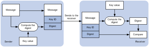
As shown in Figure 6, NTP authentication proceeds as follows:
1. The sender uses the key identified by the key ID to calculate a digest for the NTP message through the specified algorithm. Then it sends the calculated digest together with the NTP message and key ID to the receiver.
2. Upon receiving the message, the receiver performs the following actions:
a. Finds the key according to the key ID in the message.
b. Uses the key and the specified algorithm to calculate the digest for the message.
c. Compares the digest with the digest contained in the NTP message.
- If they are different, the receiver discards the message.
- If they are the same, the receiver determines whether the sender is allowed to use the authentication ID on the local end. If the sender is allowed to use the authentication ID, the receiver accepts the message. If the sender is not allowed to use the authentication ID, the receiver discards the message
Restrictions and guidelines
You can configure NTP authentication in client/server mode, symmetric active/passive mode, broadcast mode, or multicast mode. To ensure a successful NTP authentication, configure the same authentication key ID, algorithm, and key on the local device and time server. Make sure the time server is allowed to use the key ID for authentication on the local device.
NTP authentication results differ when different settings are configured on the local device and time server, as shown in Table 4, Table 5, Table 6, and Table 7. (N/A in the table means that whether the configuration is performed or not does not make any difference.)
Table 4 Results of NTP authentication in client/server mode
|
Client |
Server |
||||
|
Enable NTP authentication |
Specify the server and key |
Trusted key |
Enable NTP authentication |
Trusted key |
|
|
Successful authentication |
|||||
|
Yes |
Yes |
Yes |
Yes |
Yes |
|
|
Failed authentication |
|||||
|
Yes |
Yes |
Yes |
Yes |
No |
|
|
Yes |
Yes |
Yes |
No |
N/A |
|
|
Yes |
Yes |
No |
N/A |
N/A |
|
|
Authentication not performed |
|||||
|
Yes |
No |
N/A |
N/A |
N/A |
|
|
No |
N/A |
N/A |
N/A |
N/A |
|
Table 5 Results of NTP authentication in symmetric active/passive peer mode
|
Active peer |
Passive peer |
||||
|
Enable NTP authentication |
Specify the peer and key |
Trusted key |
Stratum level |
Enable NTP authentication |
Trusted key |
|
Successful authentication |
|||||
|
Yes |
Yes |
Yes |
N/A |
Yes |
Yes |
|
Failed authentication |
|||||
|
Yes |
Yes |
Yes |
N/A |
Yes |
No |
|
Yes |
Yes |
Yes |
N/A |
No |
N/A |
|
Yes |
No |
N/A |
N/A |
Yes |
N/A |
|
No |
N/A |
N/A |
N/A |
Yes |
N/A |
|
Yes |
Yes |
No |
Larger than the passive peer |
N/A |
N/A |
|
Yes |
Yes |
No |
Smaller than the passive peer |
Yes |
N/A |
|
Authentication not performed |
|||||
|
Yes |
No |
N/A |
N/A |
No |
N/A |
|
No |
N/A |
N/A |
N/A |
No |
N/A |
|
Yes |
Yes |
No |
Smaller than the passive peer |
No |
N/A |
Table 6 Results of NTP authentication in broadcast mode
|
Broadcast server |
Broadcast client |
|||
|
Enable NTP authentication |
Specify the server and key |
Trusted key |
Enable NTP authentication |
Trusted key |
|
Successful authentication |
||||
|
Yes |
Yes |
Yes |
Yes |
Yes |
|
Failed authentication |
||||
|
Yes |
Yes |
Yes |
Yes |
No |
|
Yes |
Yes |
Yes |
No |
N/A |
|
Yes |
Yes |
No |
Yes |
N/A |
|
Yes |
No |
N/A |
Yes |
N/A |
|
No |
N/A |
N/A |
Yes |
N/A |
|
Authentication not performed |
||||
|
Yes |
Yes |
No |
No |
N/A |
|
Yes |
No |
N/A |
No |
N/A |
|
No |
N/A |
N/A |
No |
N/A |
Table 7 Results of NTP authentication in multicast mode
|
Multicast server |
Multicast client |
|||
|
Enable NTP authentication |
Specify the server and key |
Trusted key |
Enable NTP authentication |
Trusted key |
|
Successful authentication |
||||
|
Yes |
Yes |
Yes |
Yes |
Yes |
|
Failed authentication |
||||
|
Yes |
Yes |
Yes |
Yes |
No |
|
Yes |
Yes |
Yes |
No |
N/A |
|
Yes |
Yes |
No |
Yes |
N/A |
|
Yes |
No |
N/A |
Yes |
N/A |
|
No |
N/A |
N/A |
Yes |
N/A |
|
Authentication not performed |
||||
|
Yes |
Yes |
No |
No |
N/A |
|
Yes |
No |
N/A |
No |
N/A |
|
No |
N/A |
N/A |
No |
N/A |
Examples
· Configuring NTP authentication in client/server mode
The following configuration example uses Device A as the client and Device B as the server.
a. Configure Device A.
# Enable NTP authentication.
<DeviceA> system-view
[DeviceA] ntp-service authentication enable
# Create a plaintext NTP authentication key, specifying the key ID as 42 and key value as aNiceKey.
[DeviceA] ntp-service authentication-keyid 42 authentication-mode md5 simple aNiceKey
# Configure key 42 as a trusted key.
[DeviceA] ntp-service reliable authentication-keyid 42
# Associate key 42 with NTP server 1.1.1.1 (IP address of Device B).
[DeviceA] ntp-service unicast-server 1.1.1.1 authentication-keyid 42
b. Configure Device B.
# Enable NTP authentication.
<DeviceB> system-view
[DeviceB] ntp-service authentication enable
# Create a plaintext NTP authentication key, specifying the key ID as 42 and key value as aNiceKey.
[DeviceB] ntp-service authentication-keyid 42 authentication-mode md5 simple aNiceKey
# Configure key 42 as a trusted key.
[DeviceB] interface gigabitethernet 1/0/1
[DeviceB-GigabitEthernet1/0/1] ntp-service broadcast-server authentication-keyid 42
· Configuring NTP authentication in symmetric active/passive mode
The following configuration example uses Device A as the active peer and Device B as the passive peer.
a. Configure Device A.
# Enable NTP authentication.
<DeviceA> system-view
[DeviceA] ntp-service authentication enable
# Create a plaintext NTP authentication key, specifying the key ID as 42 and key value as aNiceKey.
[DeviceA] ntp-service authentication-keyid 42 authentication-mode md5 simple aNiceKey
# Configure key 42 as a trusted key.
[DeviceA] ntp-service reliable authentication-keyid 42
# Associate key 42 with passive peer 1.1.1.1 (IP address of Device B).
[DeviceA] ntp-service unicast-peer 1.1.1.1 authentication-keyid 42
b. Configure Device B.
# Enable NTP authentication.
<DeviceB> system-view
[DeviceB] ntp-service authentication enable
# Create a plaintext NTP authentication key, specifying the key ID as 42 and key value as aNiceKey.
[DeviceB] ntp-service authentication-keyid 42 authentication-mode md5 simple aNiceKey
# Configure key 42 as a trusted key.
[DeviceB] ntp-service reliable authentication-keyid 42
· Configuring NTP authentication in broadcast mode
The following configuration example uses Device A as the broadcast client and Device B as the broadcast server.
a. Configure Device A.
# Enable NTP authentication.
<DeviceA> system-view
[DeviceA] ntp-service authentication enable
# Create a plaintext NTP authentication key, specifying the key ID as 42 and key value as aNiceKey.
[DeviceA] ntp-service authentication-keyid 42 authentication-mode md5 simple aNiceKey
# Configure key 42 as a trusted key.
[DeviceA] ntp-service reliable authentication-keyid 42
b. Configure Device B.
# Enable NTP authentication.
<DeviceB> system-view
[DeviceB] ntp-service authentication enable
# Create a plaintext NTP authentication key, specifying the key ID as 42 and key value as aNiceKey.
[DeviceB] ntp-service authentication-keyid 42 authentication-mode md5 simple aNiceKey
# Configure key 42 as a trusted key.
[DeviceB] ntp-service reliable authentication-keyid 42
# Configure Device B to operate in NTP broadcast server mode and associate key 42 with the broadcast server.
[DeviceB] ntp-service broadcast-server authentication-keyid 42
· Configuring NTP authentication in multicast mode
The following configuration example uses Device A as the multicast client and Device B as the multicast server.
a. Configure Device A.
# Enable NTP authentication.
<DeviceA> system-view
[DeviceA] ntp-service authentication enable
# Create a plaintext NTP authentication key, specifying the key ID as 42 and key value as aNiceKey.
[DeviceA] ntp-service authentication-keyid 42 authentication-mode md5 simple aNiceKey
# Configure key 42 as a trusted key.
[DeviceA] ntp-service reliable authentication-keyid 42
b. Configure Device B.
# Enable NTP authentication.
<DeviceB> system-view
[DeviceB] ntp-service authentication enable
# Create a plaintext NTP authentication key, specifying the key ID as 42 and key value as aNiceKey.
[DeviceB] ntp-service authentication-keyid 42 authentication-mode md5 simple aNiceKey
# Configure key 42 as a trusted key.
[DeviceB] ntp-service reliable authentication-keyid 42
# Configure Device B to operate in multicast server mode and associate key 42 with the multicast server.
[DeviceB] interface gigabitethernet 1/0/1
[DeviceB-GigabitEthernet1/0/1] ntp-service multicast-server 224.0.1.1 authentication-keyid 42
Authenticating SNTP messages
Security threats
When the device uses SNTP for time synchronization, it might get time information from an unauthorized time server and synchronize to an incorrect time.
Hardening recommendations
To protect the device from an unauthorized time server, configure SNTP authentication. This feature authenticates SNTP messages for security purposes. The device receives an SNTP message and gets time synchronization information from it only when the message is authenticated. If the message fails authentication, the device discards the message. This function ensures that the device does not synchronize to an unauthorized time server.
Figure 7 SNTP authentication
As shown in Figure 6, SNTP authentication proceeds as follows:
1. The sender uses the key identified by the key ID to calculate a digest for the SNTP message through the specified algorithm. Then it sends the calculated digest together with the SNTP message and key ID to the receiver.
2. Upon receiving the message, the receiver performs the following actions:
a. Finds the key according to the key ID in the message.
b. Uses the key and the specified algorithm to calculate the digest for the message.
c. Compares the digest with the digest contained in the SNTP message.
- If they are different, the receiver discards the message.
- If they are the same, the receiver determines whether the sender is allowed to use the authentication ID on the local end. If the sender is allowed to use the authentication ID, the receiver accepts the message. If the sender is not allowed to use the authentication ID, the receiver discards the message
Restrictions and guidelines
On the SNTP client, associate the specified key with the NTP server. Make sure the server is allowed to use the key ID for authentication on the client.
With authentication disabled, the SNTP client can synchronize with the NTP server regardless of whether the NTP server is enabled with authentication.
Examples
The following configuration example uses Device A as the SNTP client and Device B as the NTP server.
1. Configure Device A.
# Enable SNTP authentication.
<DeviceA> system-view
[DeviceA] sntp-service authentication enable
# Create a plaintext NTP authentication key, specifying the key ID as 42 and key value as aNiceKey.
[DeviceA] sntp-service authentication-keyid 42 authentication-mode md5 simple aNiceKey
# Configure key 42 as a trusted key.
[DeviceA] sntp-service reliable authentication-keyid 42
# Specify the NTP server (Device B) and associate key 42 with the NTP server.
[DeviceA] sntp-service unicast-server 1.1.1.1 authentication-keyid 42
2. Configure Device B.
# Enable NTP authentication.
<DeviceB> system-view
[DeviceB] ntp-service authentication enable
# Create a plaintext NTP authentication key, specifying the key ID as 42 and key value as aNiceKey
[DeviceB] ntp-service authentication-keyid 42 authentication-mode md5 simple aNiceKey
# Configure key 42 as a trusted key.
[DeviceB] ntp-service reliable authentication-keyid 42
Configuring security association and tunnel encryption for NEMO
Hardware and feature compatibility
|
Hardware |
Compatibility with configuring security association and tunnelencryption for NEMO |
|
SR6600 router series SR6600-X router series |
No |
|
MSR router series |
Yes |
|
VSR virtual routers |
No |
Hardening recommendations
To associate with the home agent, a mobile router sends a registration request that carries the security parameter index (SPI) and authentication data to the home agent. Only mobile routers that pass the authentication can associate with the home agent.
You can configure IPsec on the tunnel between a mobile router and the home agent to protect exchanged data.
Examples
# Configure an IPsec policy, and specify security parameters for the policy, such as security protocol, encryption algorithm, authentication algorithm, and packet encapsulation mode. (Details not shown.) For more information about IPsec, see Security Configuration Guide.
# Configure a security association that contains the home agent address 2.2.2.2, SPI 100, and the plaintext key @1abcdefg. Make sure the same security association is configured on the home agent.
[Sysname] ip mobile secure home-agent 2.2.2.2 spi 100 key ascii simple @1abcdefg
# Apply IPsec policy policy1 to the tunnel interface of the mobile IP tunnel.
[Sysname] ip mobile router
[Sysname-mobile-router] ipsec policy policy1
Hardening the data plane
Configuring port isolation
Hardware and feature compatibility
|
Hardware |
Port isolation compatibility |
|
SR6600 router series SR6600-X router series |
Yes |
|
MSR router series |
Yes |
|
VSR virtual routers |
No |
Security threats
If one of the hosts connected to interfaces of a device has security threats and is attacked, the host might send a large number of unicast, multicast, or broadcast packets and even spread the virus to other hosts in the same VLAN. This will affect other hosts and occupy network bandwidth.
Hardening recommendations
To avoid this security threat, configure port isolation. Port isolation allows you to add interfaces to an isolation group. Interfaces in the same isolation group cannot communicate with each other at Layer 2. Therefore, the attack against an interface is limited to the scope of the interface, and the network security is improved.
For more information about port isolation, see Layer 2—LAN Switching Configuration Guide.
Suppressing storms and controlling storms
Configuring storm suppression
Security threats
If the device receives broadcast, multicast, or unknown unicast traffic, it forwards the traffic to all interfaces except the receiving interface in the broadcast domain. This might cause broadcast storm, which degrades the forwarding performance of the device.
Hardening recommendations
Use storm suppression to monitor and control incoming broadcast, multicast, or unknown unicast traffic.
The storm suppression feature ensures that the size of a particular type of traffic (broadcast, multicast, or unknown unicast traffic) does not exceed the threshold on an interface. When the broadcast, multicast, or unknown unicast traffic on the interface exceeds this threshold, the system discards packets until the traffic drops below this threshold.
Examples
# On GigabitEthernet 1/0/1, enable broadcast, multicast, and unknown unicast storm suppression, and set the suppression threshold for these types of traffic to 10000 kbps.
<Sysname> system-view
[Sysname] interface gigabitethernet 1/0/1
[Sysname-GigabitEthernet1/0/1] broadcast-suppression kbps 10000
[Sysname-GigabitEthernet1/0/1] multicast-suppression kbps 10000
[Sysname-GigabitEthernet1/0/1] unicast-suppression kbps 10000
# Set the broadcast, multicast, and unknown unicast suppression bandwidth all to 100 kbps for VSI vpn1.
<Sysname> system-view
[Sysname] vsi vpn1
[Sysname-vsi-vpn1] restrain broadcast 100
[Sysname-vsi-vpn1] restrain multicast 100
[Sysname-vsi-vpn1] restrain unknown-unicast 100
Dropping unknown multicast data packets
Security threats
Unknown multicast data refers to multicast data for which no forwarding entries exist in the IGMP snooping or MLD snooping forwarding table. If the device receives unknown multicast data, it floods the data in the VLAN to which the data belongs. This might causes broadcast storm, which degrades the forwarding performance of the device.
Hardening recommendations
To avoid broadcast storm caused by flooding unknown multicast data packets, enable the dropping unknown multicast data packets feature. This feature enables the device to forward unknown multicast data only to the router port. If the device does not have a router port, unknown multicast data will be dropped.
Examples
# Enable dropping unknown IPv4 multicast data packets globally.
<Sysname> system-view
[Sysname] igmp-snooping
[Sysname-igmp-snooping] drop-unknown
# Enable dropping unknown IPv6 multicast data packets globally.
<Sysname> system-view
[Sysname] mld-snooping
[Sysname-mld-snooping] drop-unknown
# In VLAN 2, enable IGMP snooping and dropping unknown multicast data packets.
<Sysname> system-view
[Sysname] igmp-snooping
[Sysname-igmp-snooping] quit
[Sysname] vlan 2
[Sysname-vlan2] igmp-snooping enable
[Sysname-vlan2] igmp-snooping drop-unknown
# In VLAN 2, enable MLD snooping and dropping unknown IPv6 multicast data packets.
<Sysname> system-view
[Sysname] mld-snooping
[Sysname-mld-snooping] quit
[Sysname] vlan 2
[Sysname-vlan2] mld-snooping enable
[Sysname-vlan2] mld-snooping drop-unknown
MAC address security management
Configuring blackhole MAC address entries
Hardening recommendations
To block all frames destined for or sourced from a suspicious MAC address, configure the MAC address as a blackhole MAC address entry. The device drops all frames with a source or destination MAC address that matches a blackhole MAC address entry.
Examples
# Configure 000f-e201-0101 as a blackhole MAC address entry.
<Sysname> system-view
[Sysname] mac-address blackhole 000f-e201-0101 vlan 2
Disabling MAC address learning
Hardware and feature compatibility
|
Hardware |
Disabling MAC address learning compatibility |
|
SR6600 router series SR6600-X router series |
No |
|
MSR router series |
No |
|
VSR virtual routers |
Yes |
Hardening recommendations
MAC address learning is enabled by default. To prevent the MAC address table from being saturated when the device is under attack, disable MAC address learning. For example, you can disable MAC address learning to prevent the device from being attacked by a large number of frames with different source MAC addresses.
Examples
# Disable global MAC address learning
<Sysname> system-view
[Sysname] undo mac-address mac-learning enable
# Disable MAC address learning on VLAN 10.
<Sysname> system-view
[Sysname] vlan 10
[Sysname-vlan10] undo mac-address mac-learning enable
# Disable MAC address learning on GigabitEthernet 1/0/1.
<Sysname> system-view
[Sysname] interface gigabitethernet 1/0/1
[Sysname-GigabitEthernet1/0/1] undo mac-address mac-learning enable
# Disable MAC address learning on VSI vpn1.
<Sysname> system-view
[Sysname] vsi vpn1
[Sysname-vsi-vpn1] undo mac-learning enable
Data flow protection
Configuring MACsec
Media Access Control Security (MACsec) secures data communication on the MAC sublayer of the data link layer. MACsec provides services such as data encryption, frame integrity check, and data origin validation.
MACsec provides the following mechanisms to secure frames:
· Data encryption—MACsec enables a port to encrypt outbound frames and decrypt MACsec-encrypted inbound frames. The keys for encryption and decryption are obtained through MKA negotiation.
· Integrity check—MACsec performs integrity check when the device receives a MACsec-encrypted frame. The integrity check uses the following process:
a. Uses a key negotiated by MKA to calculate an integrity check value (ICV) for the frame.
b. Compares the calculated ICV with the ICV in the frame trailer.
- If the ICVs are the same, the device determines that the frame is legal.
- If the ICVs are different, the device determines whether to drop the frame based on the validation mode.
· Replay protection—When MACsec frames are transmitted over the network, frame disorder might occur. MACsec replay protection allows the device to accept the out-of-order packets within the replay protection window size and drop other out-of-order packets.
For more information about MACsec, see Security Configuration Guide.
Configuring IPsec
IPsec provides interoperable, high-quality, cryptography-based security for IP communications. IPsec is a security framework that includes the following protocols:
· Authentication Header (AH).
· Encapsulating Security Payload (ESP).
· Internet Key Exchange (IKE).
· Internet Key Exchange Version 2 (IKEv2).
AH and ESP are security protocols that provide security services. IKE and IKEv2 implement automatic key exchange. For more information about IPsec, see Security Configuration Guide.
Configuring group domain VPN
Most of the network data protection technologies are designed to protect unicast data. There are fewer multicast and broadcast data protection technologies. Severe security threats exist in multicast and broadcast data transmission (for example, transmission of audio and video broadcasts and multicast file transmission).
Group Domain Virtual Private Network (group domain VPN) provides a point-to-multipoint tunnel-less VPN solution. It is mainly used to protect multicast traffic.
Group domain VPN uses a group-based IPsec model. Members in a group use a common IPsec policy, which includes security protocols, algorithms, and keys.
For more information about group domain VPN, see Security Configuration Guide.
Configuring GRE security mechanisms
Security threats
The device might suffer unpredictable attacks when the device receives tampered GRE packets or GRE packets forged by illegal clients.
Hardening recommendations
GRE supports the GRE key and GRE checksum security mechanisms.
· GRE key—GRE keys ensure packet validity. The sender adds a GRE key into a packet. The receiver compares the GRE key with its own GRE key. If the two keys are the same, the receiver accepts the packet. If the two keys are different, the receiver drops the packet.
· GRE checksum—GRE checksums ensure packet integrity. The sender calculates a checksum for the GRE header and payload and sends the packet containing the checksum to the tunnel peer. The receiver calculates a checksum for the received packet and compares it with that carried in the packet. If the checksums are the same, the receiver considers the packet intact and continues to process the packet. If the checksums are different, the receiver discards the packet.
Examples
# Enable GRE checksum on GRE tunnel interface 2.
<Sysname> system-view
[Sysname] interface tunnel 2 mode gre
[Sysname-Tunnel2] gre checksum
# Configure the GRE key as @bd123 for GRE tunnel interface 2.
<Sysname> system-view
[Sysname] interface tunnel 2 mode gre
[Sysname-Tunnel2] gre key @bd123
Configuring IPsec to secure ADVPN packets
Security threats
Auto Discovery Virtual Private Network (ADVPN) enables enterprise branches that use dynamic public addresses to establish a VPN network. ADVPN uses the VPN Address Management (VAM) protocol to collect, maintain, and distribute dynamic public addresses.
By default, ADVPN does not protect packets transmitted within a dynamically established VPN network. These packets are vulnerable to attacks such as eavesdropping and tampering.
Hardening recommendations
Use IPsec profiles to secure data and control packets in ADVPN tunnels.
Examples
# Configure IPsec transform sets to specify the security protocols, authentication and encryption algorithms, and the encapsulation mode. For more information, see IPsec in Security Configuration Guide.
# Configure an IKE-mode IPsec profile that uses the IPsec transform sets.
# Apply the IPsec profile to ADVPN tunnel interface 1.
<Sysname> system-view
[Sysname] interface tunnel 1 mode advpn gre
[Sysname-Tunnel1] tunnel protection ipsec profile prf1
Configuring IPsec to secure mGRE packets
Hardware and feature compatibility
|
Hardware |
IPsec for mGRE compatibility |
|
SR6600 router series SR6600-X router series |
Yes |
|
MSR router series |
No |
|
VSR virtual routers |
No |
Security threats
Multipoint Generic Routing Encapsulation (mGRE) is a dynamic VPN technology that uses the Next Hop Resolution Protocol (NHRP).
Typically, mGRE does not protect packets transmitted within a dynamically established VPN network. These packets are vulnerable to attacks such as eavesdropping and tampering.
Hardening recommendations
Use IPsec profiles to secure data and control packets in mGRE tunnels.
Examples
# Configure IPsec transform sets to specify the security protocols, authentication and encryption algorithms, and the encapsulation mode. For more information, see IPsec in Security Configuration Guide.
# Configure an IKE-based IPsec profile that uses the IPsec transform sets.
# Apply the IKE-based IPsec profile to mGRE tunnel interface 0.
<Sysname> system-view
[Sysname] interface tunnel 0 mode mgre
[Sysname-Tunnel0] tunnel protection ipsec profile abc
Packet filtering & Traffic filtering
ACL
An access control list (ACL) is a set of rules for identifying traffic. ACLs work with other modules, such as packet filtering, QoS, and routing. These modules use ACLs to identify traffic and enforce predefined polices on the identified traffic to control network access and improve bandwidth efficiency.
Table 8 shows different ACL types based on criteria.
|
Type |
ACL number |
IP version |
Match criteria |
|
WLAN client ACL |
100 to 199 |
IPv4 and IPv6 |
SSID. |
|
WLAN AP ACL |
200 to 299 |
IPv4 and IPv6 |
AP MAC address and AP serial ID. |
|
Basic ACLs |
2000 to 2999 |
IPv4 |
Source IPv4 address. |
|
IPv6 |
Source IPv6 address. |
||
|
Advanced ACLs |
3000 to 3999 |
IPv4 |
Source IPv4 address, destination IPv4 address, packet priority, protocol number, and other Layer 3 and Layer 4 header fields. |
|
IPv6 |
Source IPv6 address, destination IPv6 address, packet priority, protocol number, and other Layer 3 and Layer 4 header fields. |
||
|
Layer 2 ACLs |
4000 to 4999 |
IPv4 and IPv6 |
Layer 2 header fields, such as source and destination MAC addresses, 802.1p priority, and link layer protocol type. |
|
User-defined ACLs |
5000 to 5999 |
IPv4 and IPv6 |
User specified matching patterns in protocol headers. |
For more information about ACLs, see ACL and QoS Configuration Guide.
Traffic filtering
Security threats
The device might be overloaded or become abnormal due to external attacks, which eventually render services unavailable. This feature protects the network against attack traffic by denying the attack traffic.
Hardening recommendations
Traffic filtering is implemented through a QoS policy. You can takes a traffic filtering action (permit or deny) on a traffic class by applying the QoS policy to an interface, globally, or VLANs. For example, you can deny packets sourced from an IP address according to network status.
Examples
# Create advanced ACL 3000, and configure a rule to match packets with source IP address 10.0.0.2.
<Device> system-view
[Device] acl advanced 3000
[Device-acl-ipv4-adv-3000] rule permit ip source 10.0.0.2 0
[Device-acl-ipv4-adv-3000] quit
# Create a traffic class named classifier_1, and use ACL 3000 as the match criterion in the traffic class.
[Device] traffic classifier classifier_1
[Device-classifier-classifier_1] if-match acl 3000
[Device-classifier-classifier_1] quit
# Create a traffic behavior named behavior_1, and configure the traffic filtering action to drop packets.
[Device] traffic behavior behavior_1
[Device-behavior-behavior_1] filter deny
[Device-behavior-behavior_1] quit
# Create a QoS policy named policy, and associate traffic class classifier_1 with traffic behavior behavior_1 in the QoS policy.
[Device] qos policy policy
[Device-qospolicy-policy] classifier classifier_1 behavior behavior_1
[Device-qospolicy-policy] quit
# Apply QoS policy policy to the incoming traffic of GigabitEthernet 1/0/1.
[Device] interface gigabitethernet 1/0/1
[Device-GigabitEthernet1/0/1] qos apply policy policy inbound
Configuring IP source guard
IP source guard (IPSG) prevents spoofing attacks by using an IPSG binding table to filter out illegitimate packets.
This feature is typically configured on user-side interfaces.
For more information about IPSG, see IP source guard configuration in Security Configuration Guide.
ASPF
The following compatibility matrix shows the support of the hardware for ASPF:
|
Hardware |
ASPF compatibility |
|
SR6600 router series SR6600-X router series |
Yes |
|
MSR router series |
No |
|
VSR virtual routers |
Yes |
A packet-filter firewall permits only trusted traffic. For a device to receive the return traffic for its requests, a packet-filter firewall must permit both the request and return traffic. In this situation, a malicious user might send attack packets or illegal requests to the device.
Advanced Stateful Packet Filter (ASPF) addresses the issues that a packet-filter firewall cannot solve. At the border of a network, ASPF can work with a packet-filter firewall to provide the network with a more comprehensive security policy that better meets the actual needs. The packet-filter firewall permits or denies packets according to ACL rules. The ASPF records information about the permitted packets to ensure that their return packets can pass through the packet-filter firewall.
For more information about ASPF, see Security Configuration Guide.
uRPF
The following compatibility matrix shows the support of the hardware for uRPF:
|
Hardware |
uRPF compatibility |
|
SR6600 router series SR6600-X router series |
Yes |
|
MSR router series |
No |
|
VSR virtual routers |
Yes |
Attackers send packets with a forged source address to access a system that uses IPv4-based authentication, in the name of authorized users or even the administrator. Even if the attackers or other hosts cannot receive any response packets, the attacks are still disruptive to the attacked target.
Attackers can also send packets with different forged source addresses or attack multiple servers simultaneously to block connections or even break down the network.
To prevent these source address spoofing attacks, use uRPF. This feature checks whether an interface that receives a packet is the output interface of the FIB entry that matches the source address of the packet. If not, uRPF considers it a spoofing attack and discards the packet.
For more information about uRPF, see Security Configuration Guide.
SMA
State Machine Based Anti-Spoofing (SMA) prevents IPv6 snooping attacks between autonomous systems by verifying source IPv6 addresses and SMA tags.
For more information about SMA, see Security Configuration Guide.
Configuring the voice VLAN security mode
Hardware and feature compatibility
|
Hardware |
Voice VLAN security mode compatibility |
|
SR6600 router series SR6600-X router series |
Yes |
|
MSR router series |
Yes |
|
VSR virtual routers |
No |
Security threats
When voice VLAN operates in normal mode, the port receives voice-VLAN-tagged packets and forwards them in the voice VLAN without examining their MAC addresses. If the PVID of the port is the voice VLAN and the port operates in manual VLAN assignment mode, the port forwards all the received untagged packets in the voice VLAN. In this mode, voice VLANs are vulnerable to traffic attacks. Malicious users might send a large number of forged voice-VLAN-tagged or untagged packets to affect voice communication.
Hardening recommendations
To protect voice traffic in an unsafe network, you can configure the voice VLANs to operate in security mode. In this mode, the port uses the source MAC addresses of voice packets to match the OUI addresses of the device. Packets that fail the match will be dropped. The security mode improves the security.
Restrictions and guidelines
As a best practice, do not transmit both voice traffic and non-voice traffic in a voice VLAN. If you must transmit different traffic in a voice VLAN, make sure the voice VLAN security mode is disabled.
Examples
# Enable the voice VLAN security mode.
<Sysname> system-view
[Sysname] voice-vlan security enable
Connection limits
A connection is an end-to-end flow identified by the quintuple (source IP address, source port number, destination IP address, destination port number, and protocol type). The connection limit feature enables the device to monitor and limit the number of established connections in the following situations:
· An external host initiates a large number of connections to an internal server and occupies server resources. The server cannot provide services for other users.
· An external host initiates a large number of connections to the device, which degrades in performance.
· An internal host initiates a large number of connections to an external server and occupies entry resources (for example, NAT entries) of the gateway device. Other internal hosts cannot communicate with the external network.
The device uses ACLs to define the connection range to limit. In addition, you can use source IP addresses, destination IP addresses, services, or any combination of them to further limit the connections. You can also limit the connection rate.
For more information about connection limits, see Security Configuration Guide.
Attack detection and defense
DoS attack detection and defense
The gateway device deployed on the public network and its downstream hosts and servers are vulnerable to DoS attacks. Victim devices cannot respond to user requests normally.
The device supports prevents the following DoS attacks:
· Single-packet attacks—ICMP redirect, ICMP destination unreachable, ICMP type, ICMPv6 type, Land, large ICMP packet, large ICMPv6 packet, IP options, IP option abnormal, IP fragment, IP impossible packet, tiny fragment, smurf, TCP flag, Traceroute, Winnuke, UDP bomb, UDP snork, UDP fraggle, Teardrop, ping of death, and IPv6 ext-header abnormal.
· Scanning attacks—IP sweep, port scan, and distributed port scan.
· Flooding attacks—SYN flood, ACK flood, SYN-ACK flood, FIN flood, RST flood, DNS flood, DNS reply flood, HTTP flood, SIP flood, ICMP flood, ICMPv6 flood, and UDP flood.
For more information about DoS attack detection and prevention, see Attack Detection and Prevention in Security Configuration Guide.
DDoS attack defense
Hosts or servers on the Internet can initiate distributed denial of service (DDoS) attacks to crash the target network temporarily or permanently. DDoS attacks have greater volume of attack traffic than traditional DoS attacks and the DDoS attack sources are more difficult to be discovered.
To protect the system against DDoS attacks, use DDoS attack defense. In the DDoS attack defense architecture, the detection and cleaner devices are responsible for detecting and cleaning attack traffic, respectively. By using the anti-DDoS zone based cleaning policy, the DDoS attack defense feature detects and filters out DDoS traffic at different tiers to effectively defend against various types of DDoS attacks.
For more information about DDoS attack defense, see Security Configuration Guide.
Configuring security policies
The following compatibility matrix shows the support of the hardware for security policy:
|
Hardware |
Security policy compatibility |
|
SR6600 router series SR6600-X router series |
Yes |
|
MSR router series |
No |
|
VSR virtual routers |
Yes |
A security policy defines a set of rules for forwarding control and Deep Packet Inspection (DPI). It matches packets against the rules and takes the action stated in the rules on the matched packets.
Security policies can provide the same 5-tuple filtering functions as packet filtering, and support precise network management of packets transmitted between specific security zones based on application, protocol, and user. By partnering with DPI, it can also provide security protection services such as intrusion protection, URL filtering, data filtering, file filtering, and antivirus.
For more information about security policies, see Security Configuration Guide.
