| Title | Size | Downloads |
|---|---|---|
| 15-H3C EIA 802.1X Authentication and Anti-Proxy Configuration Examples-book.pdf | 1.58 MB |
- Table of Contents
- Related Documents
-
| Title | Size | Download |
|---|---|---|
| book | 1.58 MB |
|
|
|
H3C EIA 802.1X Authentication and Anti-Proxy Configuration Examples |
|
|
|
|
Software version: EIA (E6203)
Document version: 5W103-20240226
Copyright © 2024 New H3C Technologies Co., Ltd. All rights reserved.
No part of this manual may be reproduced or transmitted in any form or by any means without prior written consent of New H3C Technologies Co., Ltd.
Except for the trademarks of New H3C Technologies Co., Ltd., any trademarks that may be mentioned in this document are the property of their respective owners.
The information in this document is subject to change without notice.
Introduction
Anti-IE proxy and anti-proxy server features are used to prevent unauthorized user access to the network. For example, a computer has special access permissions (such as Internet access, using instant messaging software QQ and MSN), while other computers do not. However, these other computers can illegally obtain such special access permissions through the proxy server installed on the first computer. The iNode client, Intelligent Management Center (IMC), and access device can collaborate to provide anti-proxy features.
Feature usage guidelines
Application scenarios
The following information applies to networks that need to block the access of users who use an IE proxy or a proxy server.
Prerequisites
Endpoint users must use the iNode client to establish a connection to the network.
Example: Configuring 802.1X authentication and anti-proxy features
Network configuration
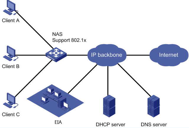
As shown in Figure 1, deploy the EIA as an 802.1X authentication server to authenticate Internet access users on the network and configure anti-proxy features on EIA to prevent users from accessing the Internet by using an IE proxy or a proxy server.
In this example, the IP address of the EIA server is 192.168.7.196. The IP address of the access device is 172.19.254.177. The user has a PC installed with the iNode client, Internet Explorer (IE) browser, and proxy server software CCProxy.
Restrictions and guidelines
In a cluster deployment, specify the northbound service virtual IP as the IP address of the EIA server. Do not specify the node IP address of the EIA server.
To identify the northbound service virtual IP of the EIA server in a cluster deployment:
1. Enter https://ip_address:8443/matrix/ui in the address bar of the browser to open the Matrix page. ip_address represents the northbound service virtual IP or node IP address.
2. On the top navigation bar, click DEPLOY.
3. From the left navigation pane, select Clusters.
4. Click the Cluster Parameters tab. Use the IP address in the Northbound Service Virtual IP field as the IP address of the EIA server.
Software versions used
This configuration example was created and verified on the following software and hardware:
· EIA server: EIA (E6203)
· Access device: H3C S5560-54C-PWR-EI Comware Software, Version 7.1.045, Release 1122P01
· iNode client: iNode PC 7.3 (E0558)
Procedures
Configuring the EIA server
Configure the following items on the EIA server:
· Access device
· Access policy
· Access service
· Access user
· Proxy server detection parameters
Adding an access device
You must add an access device to the EIA server before the EIA server can work with the access device for authentication.
To add an access device to the EIA server:
1. On the top navigation bar, click Automation.
2. From the left navigation pane, select User > Access Service. Click the Access Device Management tab.

3. On the Access Device tab, click Add.
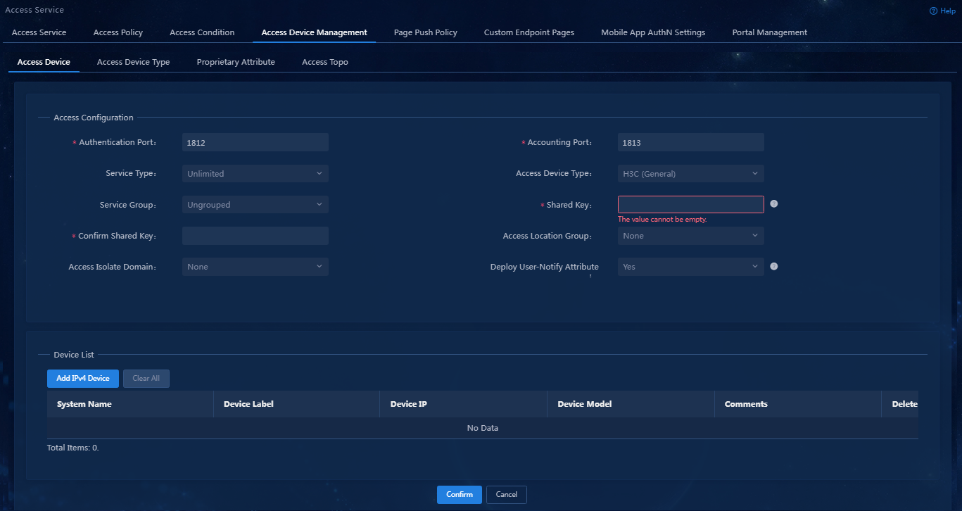
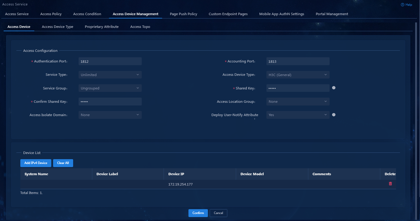
Figure 3 Adding an access device
Access configuration parameters
¡ Authentication Port/Accounting Port: Specify the RADIUS authentication/accounting service port on the EIA server. It must be the same as that specified on the access device. This example uses the default authentication service port 1812 and default accounting service port 1813.
|
|
IMPORTANT: You must use the EIA server to provide both authentication and accounting services. You cannot use the EIA server as the authentication server and another server as the accounting server. |
¡ Access Device Type: Select the access device type from list. Options include STANDARD (standard), pre-defined, vendor-specific types, and administrator-defined, vendor-specific types. You can select STANDARD for any access devices that support the standard RADIUS protocol. The system predefined vendor-specific types include H3C(General), 3COM(General), HUAWEI(General), CISCO(General), RG(General), HP(MSM), HP(Comware), MICROSOFT(General), JUNIPER(General), HP(ProCurve) and ARUBA(General). This example uses H3C(General).
¡ Service Group: Select a service group for the access device for hierarchical management.
¡ Shared Key/Confirm Shared Key: Enter a shared key in the Shared Key field. If the system is configured to display keys in cipher text, you must enter the key again in the Confirm Shared Key field for confirmation. The shared key is used for secure communication between the server and the access device. The shared key specified on the EIA server must be the same as that specified on the access device. You only need to enter the shared key once if you selected Plaintext for the Displays Key in field in system parameter settings on the Automation > User > Service Parameters > Access Parameters > System Settings page. In this example, the shared key is expert.
¡ Access Location Group: Select an access location group for the access device. You can select an existing access location group or None. The access device group is one of the user access conditions.
4. Click Add IPv4 Device in the device list to manually add an access device. In the window that opens, configure the parameters for the access device, and then click Confirm.
When you specify the IP address of the access device, examine the applicable RADIUS scheme on the access device to identify the IP address to specify.
¡ If the RADIUS scheme contains a NAS IP specified by using the nas-ip command for the access device, specify that IP address as the access device IP on the EIA server.
¡ If the RADIUS scheme does not contain a NAS IP, specify the IP address of the Layer 3 Ethernet interface or VLAN interface that connects the access device to the EIA server.
Figure 4 Manually adding an access device
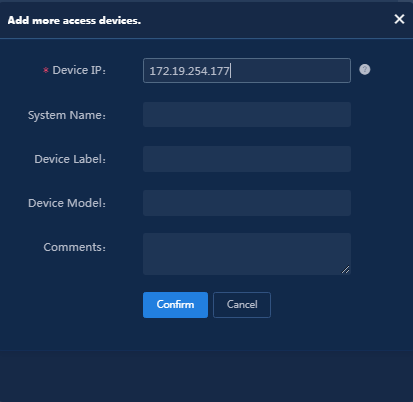
Figure 5 Access device parameter configuration
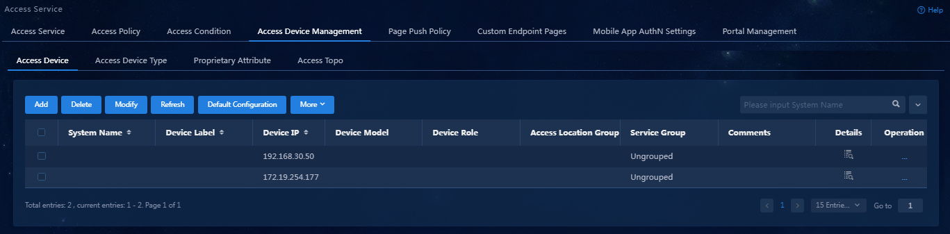
5. Click Confirm. Verify that the access device has been added to the access device list.
Figure 6 Viewing the newly added access device
Configuring an access policy
This configuration example adds an access policy that contains anti-IE proxy and anti-proxy server settings.
Add an access policy as follows:
1. On the top navigation bar, click Automation.
2. From the left navigation pane, select User > Access Service. Click the Access Device Management > Access Policy tab.

3. Click Add to enter the page for adding an access policy.
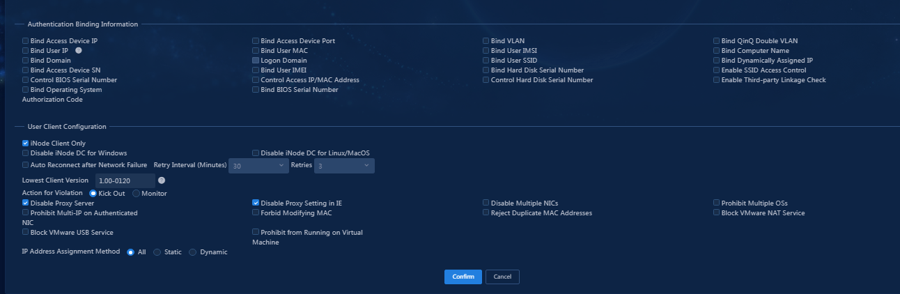
¡ In the Basic Information area, enter the name of the access policy.
¡ In the User Client Configuration area:
- Select iNode Client Only.
- Select Disable Proxy Server and Disable Proxy Settings in IE.
- Use the default settings for other parameters.
Figure 8 Adding an access policy

Access policy parameters
¡ Access Period: Select an access period policy from the list. A user using the access policy can access the network only in the time ranges defined in the access period policy.
¡ Allocate IP: Specify whether to assign IP addresses to users.
¡ Upstream Rate (Kbps)/Downstream Rate (Kbps): Specify the maximum upstream rate and downstream rate for users that match the access policy.
¡ Priority: Specify the traffic priority during network congestion. A smaller value indicates a higher priority. Select a priority value from the priority values supported by the device. An invalid value might result in failures of endpoint users to access the network.
¡ Authentication Type/Subtype: Select an EAP authentication type. During EAP authentication, the RADIUS server deploys this EAP authentication type to the client. Options include EAP-MD5, EAP-TLS, EAP-TTLS, and EAP-PEAP. If you select the EAP-TTLS or EAP-PEAP authentication type, select EAP-MSCHAPv2, EAP-MD5, or EAP-GTC as the subtype.
- EAP-MD5: CHAP-based EAP authentication.
- EAP-TLS: Certificate-based identity authentication, which uses the TLS protocol to implement identity authentication and requires PKI for certificate management. The server and client use certificates for identity authentication. If authentication succeeds, the two sides negotiate a shared key, session ID, and cipher suite (encryption, compression, and data integrity check) to set up a secure and reliable communication channel. . EAP-TLS uses the session ID for fast reauthentication, which greatly simplifies the authentication process. It also supports fragmentation of large TLS packets..
- EAP-TTLS: Certificate-based identity authentication, which initiates subauthentication within the security channel set up by TLS authentication between the client and EIA. The authentication method protects the user identity and the EAP authentication negotiation process. Subauthentication types include EAP-MSCHAPv2, EAP-MD5, and EAP-GTC. If you select the EAP-TTLS authentication type, you must also select an EAP subtype on EIA. However, in the actual authentication process, an endpoint can ignore EIA configuration and use the endpoint's configuration for authentication if it uses a non-EAP subtype, such as PAP.
- EAP-PEAP: Certificate-based identity authentication, which initiates EAP authentication within the security channel set up by TLS authentication between the client and EIA. The authentication method protects the user identity and the EAP authentication negotiation process. EIA only supports EAP-MSCHAPv2, EAP-MD5, and EAP-GTC authentication types.
¡ EAP Auto Negotiate: Specify whether to enable automatic negotiation of EAP authentication types when the EAP authentication types specified on the client and EIA are different. With this feature enabled, EIA permits the client's authentication request without considering the EAP type configured on the client. With this feature disabled, EIA rejects the client's authentication request if the EAP authentication types specified on the client and EIA are different.
¡ Maximum Online Duration for a Logon (Minutes): Specify the maximum online duration in minutes for a successfully authenticated user that uses the access policy. The value is an integer in the range of 1 to 1440. If you leave this field empty, the online duration is not limited. If you specify a value and the online duration of an access user exceeds the specified value, EIA forces the user to go offline.
¡ Deploy VLAN: Specify a VLAN ID or name for deployment to users. After passing authentication, users can access resources in the specified VLAN only. On the access device, configure the VLAN assignment mode as integer or string type accordingly:
- If the type of the access device is H3C (General), HUAWEI (General), HP (Comware), or 3COM (General), you can enter a VLAN ID or VLAN name. EIA takes any integer in the range of 1 to 4094 as an integer-type VLAN ID and deploys it to the access device. Any other character string is taken as a string-type VLAN name and deployed to the access device.
- If the access device is none of the previous types, EIA always deploys the entered value to the access device as a string-type VLAN name.
¡ Deploy Address Pool: Enter an address pool name to be deployed to the access device. The access device will use this address pool to assign IP addresses to users. For successful address assignment, make sure an address pool with the same name exists on the access device..
¡ Deploy User Profile: Specify the name of the user profile to be deployed to the access device. The access device will use the user profile to perform user-based QoS functions. This feature takes effect only when the user profile to be deployed has been configured on the device.
¡ Deploy User Group: Specify the name of the user group to which the users belong after they pass authentication. You can enter multiple user groups, separated by semi-colons (;). This feature takes effect only when EIA works with an SSL VPN device or collaborates with ACG 1000.
¡ Deploy ACL: Manually enter an ACL or select an ACL from the ACL list. You can configure the ACL list on the Access Policy > Access ACL page.
¡ Offline Check Period (Hours): Specify the offline check interval for mute terminals, in hours. The value must be an integer in the range of 0 to 596523. After a mute terminal passes authentication, EIA deploys the configuration to the device and the device checks whether the mute terminal is offline at the specified periods. If you leave this field empty or set the value to 0, offline check will not be performed.
¡ Authentication Binding Information: EIA cooperates with the access device to check the binding information for each user account to be authenticated, including the IP address, port, VLAN, QinQ double VLAN, and SN of the access device, and the IP address, MAC address, IMSI, IMEI, wireless user SSID and the hard disk serial number of the user endpoint. The iNode client cooperates with the policy server to check the following binding information of the user: user IP address, MAC address, computer name, computer domain, logon domain and hard disk serial number. Among the binding items, user MAC address and IMSI are mutually exclusive and cannot be bound at the same time. You can configure binding information for an access policy and apply the access policy in an access service. If a user uses an access service that applies an access policy without binding information, auto learning is adopted. In this case, EIA binds the parameters used in the first login of a user. For example, if a user uses 10.100.10.10 for the first login through the service, the user must always use the IP address for future authentication.
- Control Hard Disk Serial Number: With this feature enabled, EIA checks the hard disk serial number of a user endpoint when the user attempts to come online. If the serial number is permitted or EIA cannot obtain the hard disk serial number, the user is allowed to come online. Otherwise, the access is denied. This feature must work with the iNode PC client.
- Enable SSID Access Control: When you enable this feature and set the SSID filter to Permit, EIA maintains an SSID allowlist. Users can access the network when they connect to an SSID on the SSID access control list. When you enable this feature and set the SSID filter to Deny, EIA maintains an SSID denylist. Users cannot access the network when they connect to an SSID on the SSID access control list. This feature must work with the iNode PC client. The client receives the SSID access control configuration from EIA and saves it to the PC. The configuration also applies to the Windows built-in 802.1X application.
|
|
NOTE: To deploy authorization information, make sure the attributes are supported on the device. For the authentication binding information to take effect, you must configure the corresponding information in the RADIUS attributes on the device. In this example, you do not need to deploy authorization information. The default settings apply. |
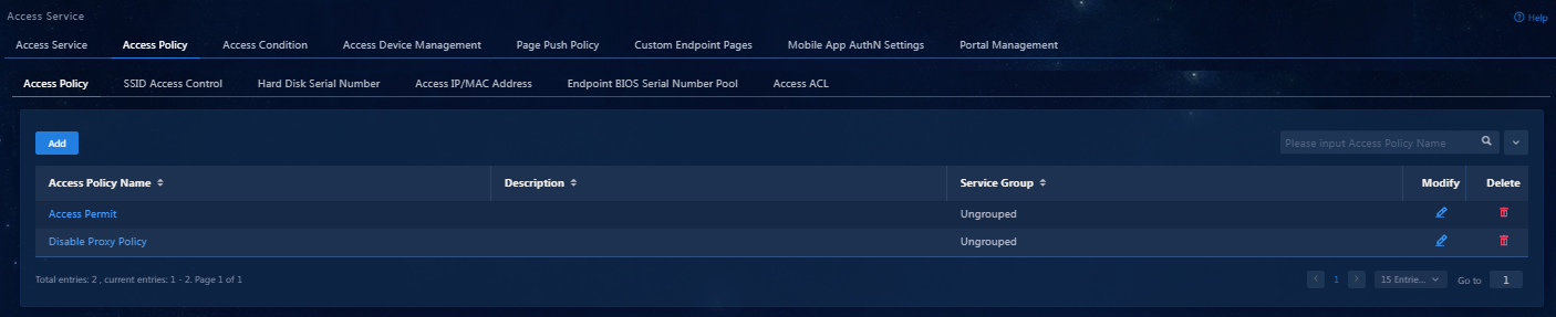
4. Click Confirm. Verify that the access policy has been added to the access policy list.
Figure 9 Viewing the added access policy
Adding an access service
An access service is a collection of policies for user authentication and authorization. This example adds a simple access service that does not contain any access control settings.
To add an access service:
1. On the top navigation bar, click Automation.
2. From the left navigation pane, select User > Access Service.
3. Click Add. On the page that opens, configure the following parameters:
¡ Service Name: Specify a service name. A service name uniquely identifies an access service in EIA. In this example, 802.1X Service is used.
¡ Service Suffix: Enter a service suffix, which identifies the name of the domain to be used for user authentication. The service suffix, authentication username, authentication domain, and the device's RADIUS scheme command are closely related to each other. For more information about the matrix of these elements, see Table 1.
¡ Default Access Policy: Specify an access policy as the default access policy.
¡ Transparent Authentication: Specify whether to support transparent portal authentication. In this example, this option is selected. With this option selected, when the user accesses the network for the first time, the user must perform authentication. Before the endpoint aging time expires, the user does not need to re-authenticate if the user goes offline and then comes online again. If this option is not selected, the user has to authenticate every time it comes online.
¡ Default Proprietary Attribute Assignment Policy: Specify the default proprietary attribute assignment policy. If a user that uses the service does not match an access device group when the user accesses the network, the system deploys proprietary attributes to the access device according to the configuration of the default proprietary attribute assignment policy.
¡ Default Max. Devices for Single Account: Specify the number of endpoints to be bound to the same user account in access scenarios that are not included in the service. This field is available only when the EIP component is deployed.
- EIA checks the maximum number of bound endpoint devices for a single account in the following order:
-
Matched access scenario: Checks the number of bound
endpoint devices against the maximum number limit specified in the scenario. If
the number reaches the limit, EIA denies the user authentication.
- Scenarios in all services: Checks the number of bound endpoint devices in scenarios of all assigned services for the account. If the number reaches the value of Max. Device for Single Account specified in user endpoint settings on the Automation > User > Service Parameters > Access Parameters > System Settings page, EIA denies the user authentication.
¡ Default Max. Number of Online Endpoints: Specify the maximum number of online endpoints using the same user account in access scenarios that are not included in the service.
¡ Daily Max. Online Duration: Specify the total duration in a day that an account can access the network by using the service. When the limit is reached, the account is forced offline and cannot access the network this day. The value can be an integer in the range of 0 to 1440 minutes. A value of 0 means no limit.
¡ Description: Enter a description for the access service.
|
Authentication Username |
Authentication Domain |
Device's RADIUS Scheme Command |
Service Suffix on EIA |
|
X@Y |
Y |
user-name-format with-domain |
Y |
|
user-name-format without-domain |
No suffix |
||
|
X |
[Default Domain] Default domain on the device |
user-name-format with-domain |
[Default Domain] |
|
user-name-format without-domain |
No suffix |
Figure 11 Adding an access service

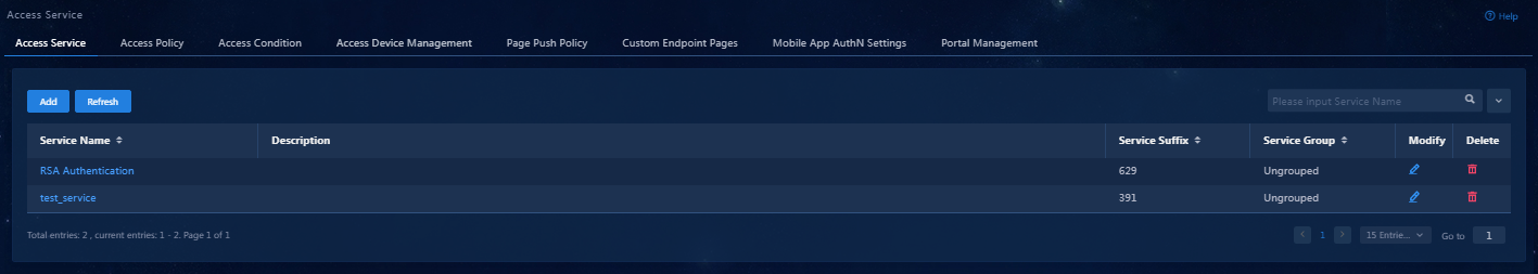
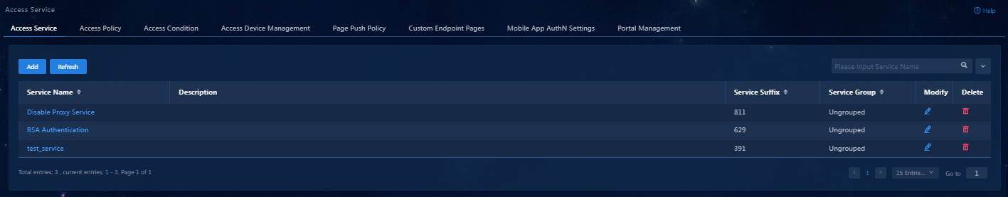
4. Click Confirm. Verify that the added access service has been added to the access service list.
Figure 12 Viewing the added access service
Adding an access user
You must configure the identification information of an access user on EIA, including the username, password, access service, and other information.
To add an access user:
1. On the top navigation bar, click Automation.
2. From the left navigation pane, select User > Access User.
3. Click Add. On the page that opens, configure the access user parameters.
¡ User Name: Specify a username for the
access user. In this example, the user name is user.
Identity Number: Specify an identity number for the
access user. In this example, the user identity number is 111111.
¡ Account Name: Specify an account name to uniquely identify the access user. The access user can use the account name to subscribe to and use services. The account name can contain a maximum of 200 characters and cannot include the TAB character or any of characters #+/?%&=*'@\"[]()<>`. In this example, the account name is user.
¡ Password/Password Confirm: Enter the password for authentication and enter the password again for confirmation.
¡ Access Service: Select the access service added in "Adding an access service."
¡ Use the default settings for other parameters.
Figure 14 Access user configuration

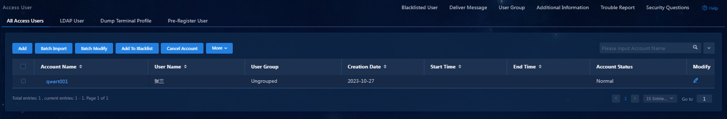
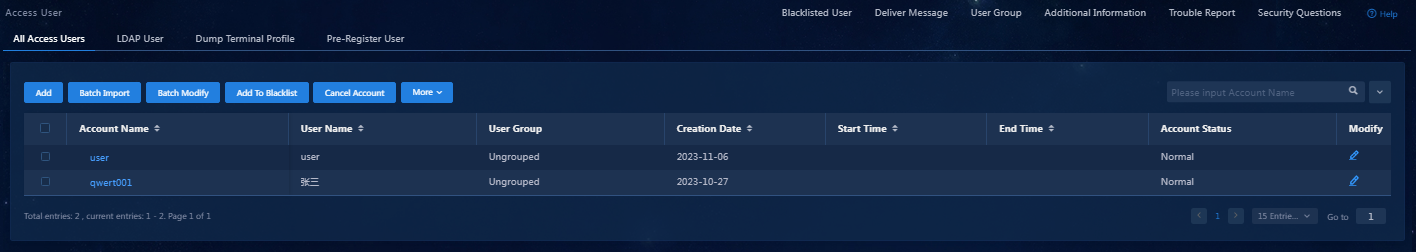
4. Click Confirm. Verify that the added access user has been added to the access user list.
Figure 15 Verifying that the added access user has been added
Configuring the proxy server detection parameters
Generally, a host enabled with a proxy service will forward a large number of packets to other hosts. EIA has defined the parameters for detecting the proxy server. These parameters are issued to the iNode client, which determines whether the host has enabled with proxy server.
In this example, some users send internal network packets from non-local network segments via proxy servers. To detect such events, it's required to specify the internal network segments to be detected.
To configure the proxy server detection parameters:
1. On the top navigation bar, click Automation.
2. From the navigation pane, select User > Service Parameters > Access Parameters.
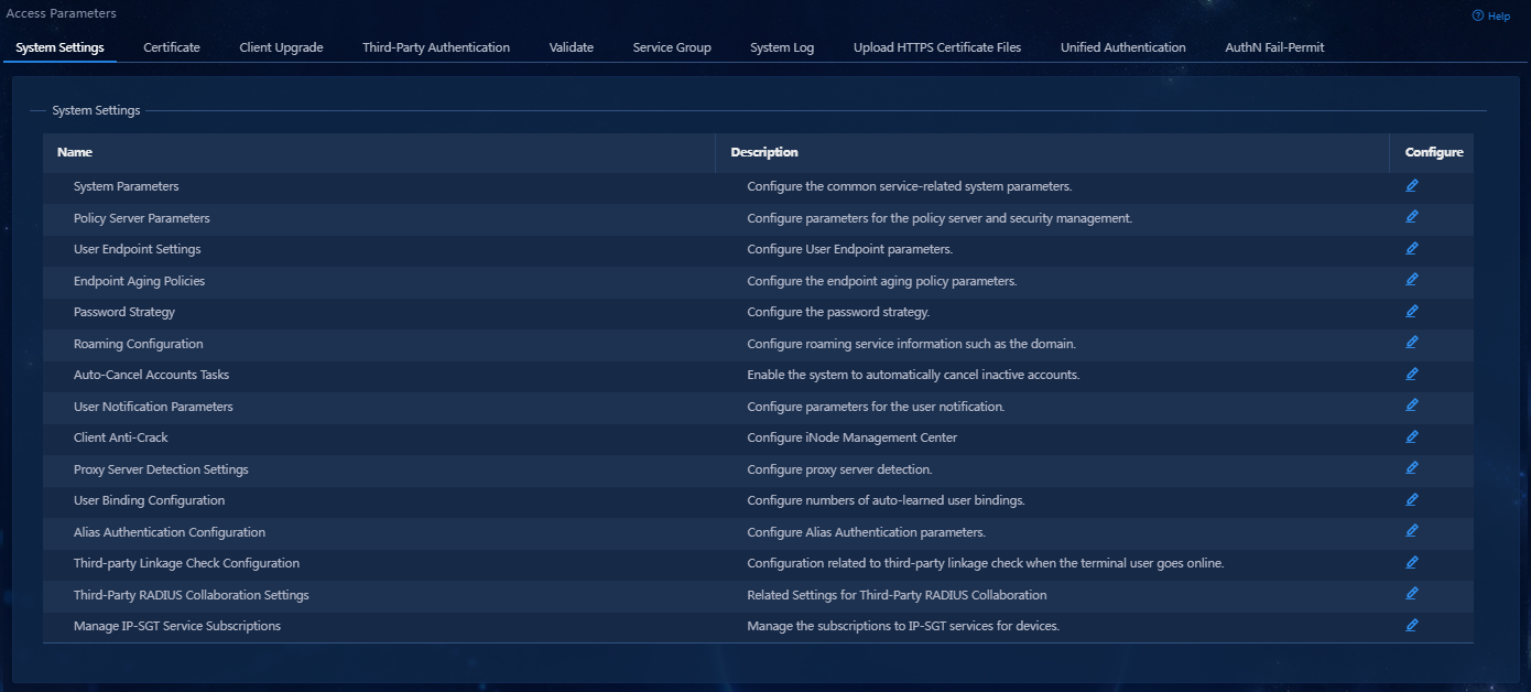
3. On the System Settings
tab, click the Configure icon ![]() for the Proxy Server Detection Settings
item.
for the Proxy Server Detection Settings
item.
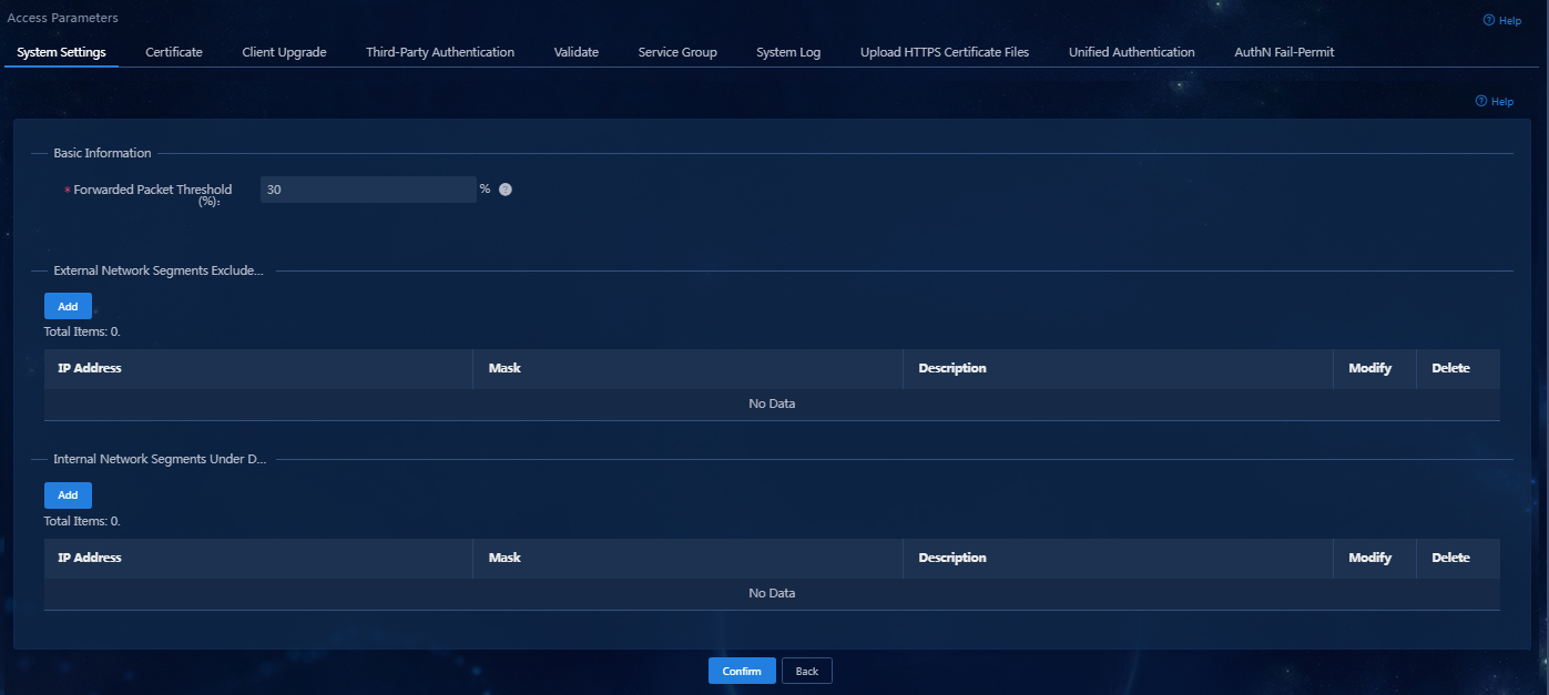
On the page that opens, configure the Forwarded Packet Threshold, External Network Segments Excluded from Detection, and Internal Network Segments Under Detection settings.
¡ By default, no network segments are configured. The iNode client counts all packets coming from the external network on the authenticated NIC, as well as packets transmitted to the local host’s network segments through this NIC. For example, if the IP address of the host where the iNode client is located is 192.168.1.1/24, all packets from the external network and those sent to the 192.168.1.0/24 network segment will be counted by the iNode client.
¡ The iNode client does not count packets coming from the network segments added to the External Network Segments Excluded from Detection list.
¡ The iNode client will count packets sent to the network segments added to the Internal Network Segments Under Detection list.
Figure 17 Proxy server detection parameters
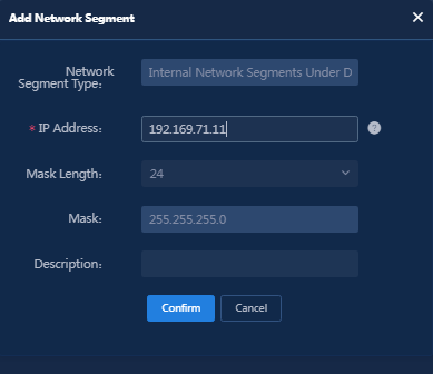
4. Click Add in the Internal Network Segments Under Detection area. On the page that opens, enter the IP address and select the mask length.
Figure 18 Adding a network segment to be detected
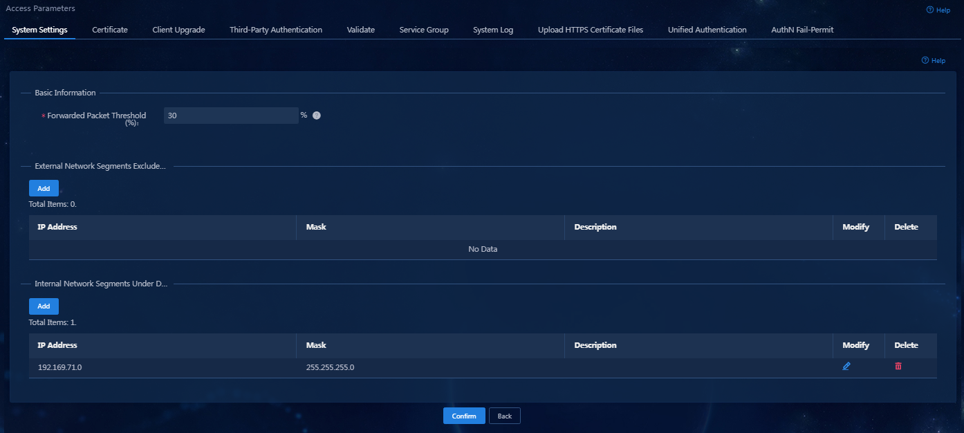
5. Click Confirm. Verify that the network segment has been added to the Internal Network Segments Under Detection list.
Figure 19 Internal network segments to be detected
Configuring the access device
Configure the access device to perform RADIUS-based 802.1X authentication on users to make sure only users who have passed authentication can access the network.
Log in to the CLI of the access device, for example, through Telnet:
<H3C>system-view
System View: return to User View with Ctrl+Z.
[H3C]radius scheme zz
New RADIUS scheme
[H3C-radius-zz]primary authentication 192.168.7.196 1812
[H3C-radius-zz]primary accounting 192.168.7.196 1813
//Specify the EIA server as the primary authentication server and primary accounting server. Make sure the authentication port and accounting port are the same as those specified on the EIA server in "Adding an access device."
[H3C-radius-zz]key authentication simple movie
[H3C-radius-zz]key accounting simple movie
//Make sure the shared keys are the same as those specified on the EIA server in "Adding an access device."
[H3C-radius-zz]user-name-format with-domain
//Include domain names in the usernames sent to the RADIUS server. For more information about the configuration matrix of related elements configured on EIA and the access device, see Table 1.
[H3C-radius-zz]quit
[H3C]domain 811
New Domain added.
Make sure the domain name is the same as the service suffix specified on the EIA server.
[H3C-isp-811]authentication lan-access radius-scheme zz
[H3C-isp-811]authorization lan-access radius-scheme zz
[H3C-isp-811]accounting lan-access radius-scheme zz
//The ISP domain uses RADIUS scheme zz for authentication, authorization, and accounting.
[H3C-isp-811]quit
[H3C]dot1x
[H3C]interface GigabitEthernet 1/0/39
[H3C-GigabitEthernet 1/0/39]dot1x
[H3C-GigabitEthernet 1/0/39]quit
[H3C]dot1x authentication-method chap
//For the 802.1X feature to take effect on an interface, you must enable the feature both globally and on that interface.
Verifying the configuration
Verify that the user can pass 802.1X authentication by entering the authentication username and password on the iNode PC client.
Installing the iNode client
Install an iNode client with the 802.1X connection function.
|
|
NOTE: The EIA server is compatible with all versions of iNode clients. |
Setting an IE proxy and initiating authentication
After a user performs authentication on the iNode client and comes online, the iNode client automatically checks if the user has set an IE proxy and continuously monitors the user's behaviors. If it detects that the user has set an IE proxy, the user will be forced offline even if the user does not use the IE proxy.
1. Enable the IE proxy function.
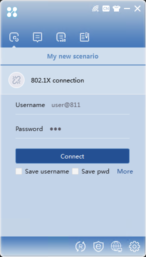
2. Open the iNode client, and select 802.1X connection. Enter the username and password, and then click Connect.
Figure 20 802.1X authentication connection page
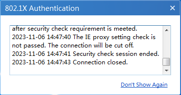
3. After the authentication succeeds, the iNode client detected that the user has set up an IE proxy, so it forces the user to go offline, as shown in Figure 21.
Figure 21 IE proxy setting check failed
Enabling the proxy server to provide proxy services
After a user performs authentication on the iNode client and comes online, the iNode client automatically checks if the user has provided the proxy service and continuously monitors the user's behaviors. If it detects that the user has provide a proxy service, the user will be forced offline.
|
|
CAUTION: If the proxy server is enabled but not providing proxy services, EIA will not force the user to go offline. |
1. Use the 802.1X connection on the iNode client to initiate authentication and successfully pass the authentication to come online.
2. On the user host, enable the proxy server and provide proxy services to external users.
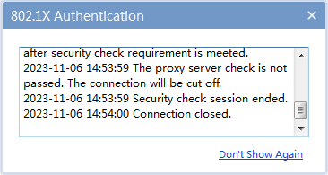
In the authentication information area of the iNode client, you can see that the iNode client has detected the proxy server and forced the user to go offline, as shown in Figure 22.
Figure 22 The proxy server check failed