| Title | Size | Downloads |
|---|---|---|
| 11-H3C EIA 802.1X Authentication and PC Binding Configuration Examples-book.pdf | 1.67 MB |
- Table of Contents
- Related Documents
-
| Title | Size | Download |
|---|---|---|
| book | 1.67 MB |
H3C EIA 802.1X Authentication and PC Binding
Configuration Examples
Product Version: EIA (E6604)
Document version: 5W103-20240226
Copyright © 2024 New H3C Technologies Co., Ltd. All rights reserved.
No part of this manual may be reproduced or transmitted in any form or by any means without prior written consent of New H3C Technologies Co., Ltd.
Except for the trademarks of New H3C Technologies Co., Ltd., any trademarks that may be mentioned in this document are the property of their respective owners.
The information in this document is subject to change without notice.
Introduction
PC binding enables you to associate the access account with the endpoint computer name, IP address, domain user, and other identity information. This feature can enhance the security of user authentication and prevent unauthorized access and theft of access accounts.
Feature usage guidelines
Application scenarios
The following information applies to enterprise networks or campus networks requiring access accounts to bind devices or endpoints.
Prerequisites
The endpoint user must use the iNode client to connect to the network.
Example: Configuring 802.1X authentication and PC binding
Network configuration
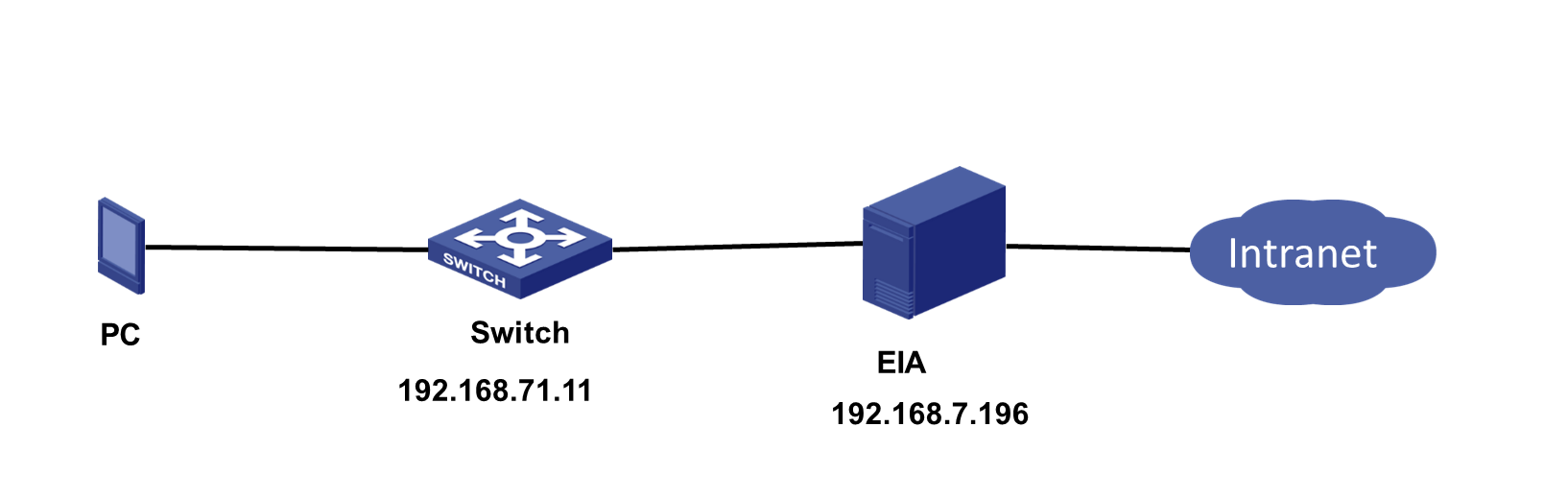
This case uses 802.1X authentication as an example to demonstrate the configuration process for binding access accounts to endpoint IP and MAC addresses, as shown in Figure 2.
· The IP address of the EIA server is 192.168.7.196. In a cluster deployment, specify the northbound service virtual IP as the IP address of the EIA server. Do not specify the node IP address of the EIA server. To identify the northbound service virtual IP of the EIA server in a cluster deployment:
a. Enter https://ip_address:8443/matrix/ui in the address bar of the browser to open the Matrix page. ip_address represents the northbound service virtual IP or node IP address.
b. On the top navigation bar, click DEPLOY. From the left navigation pane, select Clusters. Click the Cluster Parameters tab. Use the IP address in the Northbound Service Virtual IP field as the IP address of the EIA server.
· IP address of the access device: 192.168.71.11
· The PC is using the Windows operating system and has the iNode client installed.
Software versions used
This configuration example was created and verified on the following software and hardware:
· EIA: EIA (E6604)
· Access device: H3C S5560-54C-PWR-EI Comware Software,Version 7.1.045,Release 1122P01
· iNode: iNode PC 7.3 (E0585)
Procedures
Configuring the EIA server
Configure the following items on the EIA server:
Adding an access device
You must add an access device to the EIA server before the EIA server can work with the access device for authentication.
To add a device:
1. On the top navigation bar, click Automation.
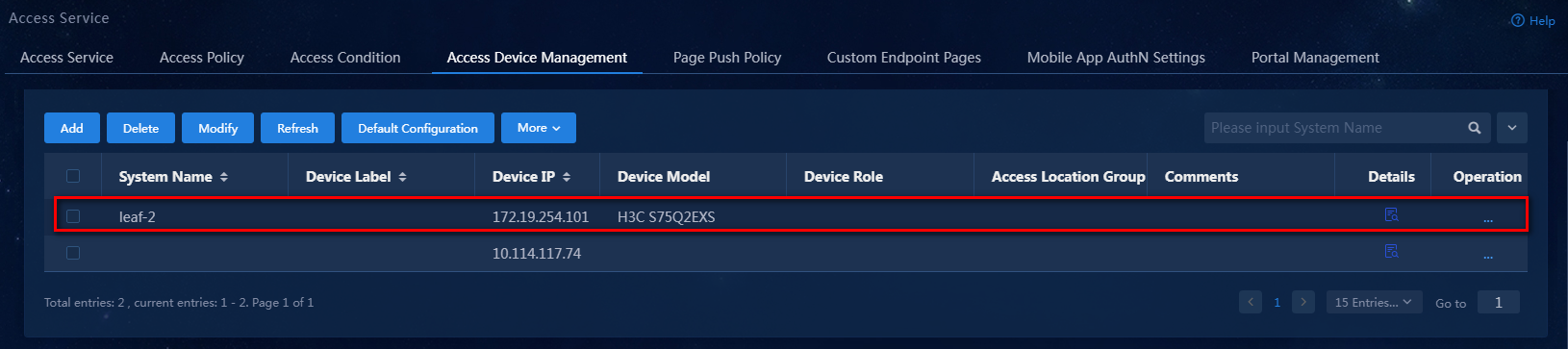
2. From the navigation pane, select User > Access Service > Access Device Management.
Figure 2 Access device configuration page
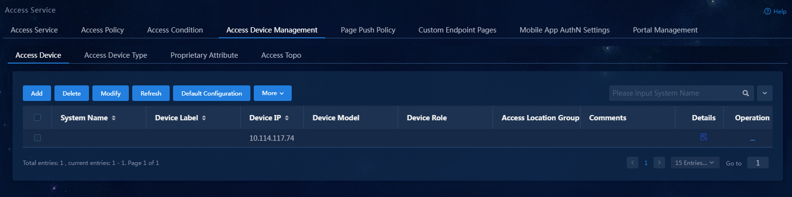
3. Click Add.
Figure 3 Adding an access device

4. Configure the access device.
The IP address of the access device must meet the following requirements:
¡ If the RADIUS scheme contains a NAS IP specified by using the nas ip command for the access device, specify that IP address on the EIA server.
¡ If the RADIUS scheme does not contain a NAS IP, specify the IP address of the Layer 3 Ethernet interface or VLAN interface that connects the access device to the EIA server.
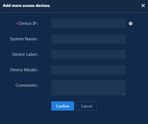
To configure the access device:
Click Add IPv4 Device in the Device List area. In the window that opens, enter the IP address of the access device in the Device IP field, and then click Confirm.
Figure 4 Adding an access device
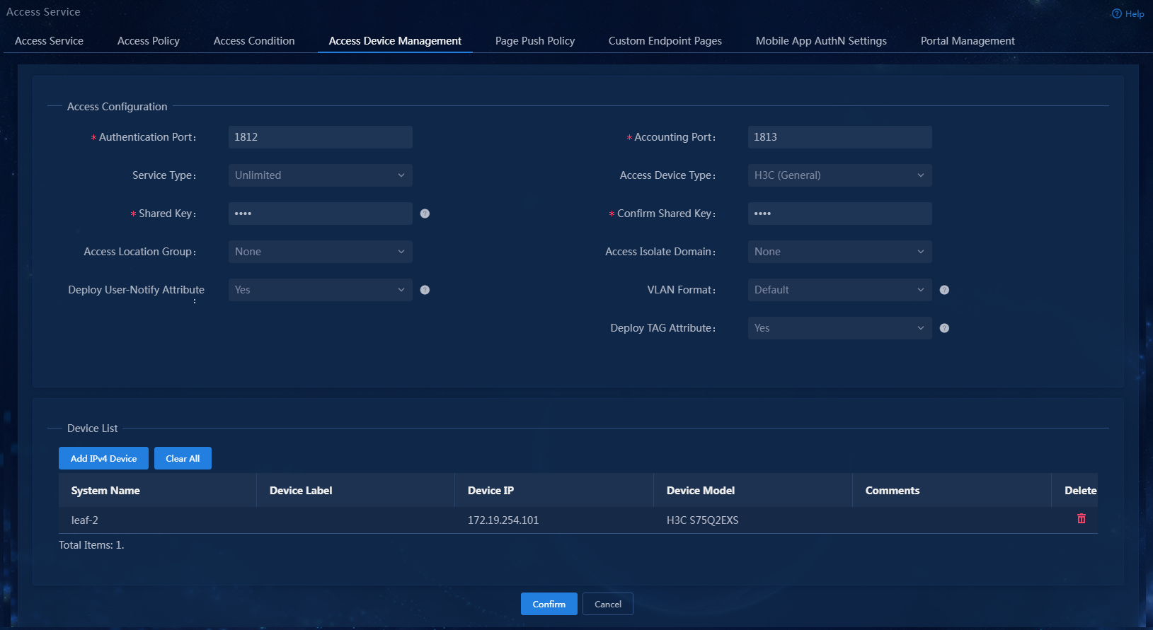
5. Configure the following common parameters:
¡ Authentication Port: Specify a port number for EIA to listen for RADIUS authentication packets. The authentication port must be the same as that specified in the RADIUS scheme on the access device. Typically, use the default port 1812.
¡ Accounting Port: Specify a port for EIA to listen for RADIUS accounting packets. The accounting port must be the same as that specified in the RADIUS scheme on the access device. Typically, use the default port 1813.
|
|
NOTE: You must use the EIA server to provide both authentication and accounting services. You cannot use the EIA server as the authentication server and another server as the accounting server. |
¡ Service Type: Specify the type of service supported by the access device. Options include Unlimited and Device Management Service. The former is for user access and network usage, while the latter is for device administrators to log in and manage the device.
¡ Access Device Type: Select the vendor or protocol type of the access device. Available options include STANDARD (Standard), predefined vendors and types, and administrator-defined vendors and types. The STANDARD (Standard) type requires the RADIUS RADIUS protocol compatibility. The predefined vendors include H3C (General), 3COM (General), HUAWEI (General), CISCO (General), RG (General), HP (MSM), HP (Comware), MICROSOFT (General), JUNIPER (General), HP (ProCurve) and ARUBA (General).
¡ Shared Key/Confirm Shared Key: Specify a shared key and confirm it. The access device and the EIA server use the shared key to validate each other. The shared key must be the same as that configured in the RADIUS scheme on the access device. You only need to enter the shared key once if you selected Plaintext for the Displays Key in field in system parameter settings on the Automation > User > Service Parameters > Access Parameters > System Settings page.
¡ Access Location Group: Select an access location group for the access device. Options include the existing access location groups on EIA and None. Access location group is one of the access conditions used to distinguish endpoint users.
¡ Service Group: Select a service group for the service. The service group ensures privilege management of the access device. The administrators and maintainers can configure access devices in service groups to which they have the management privileges.
¡ Deploy User-Notify Attribute: Select whether to enable the device to deploy configurations to endpoints through the User-Notify attribute. The deployed configurations enable the endpoints to perform tasks such as initiating security checks. As a best practice, enable this feature for H3C, Huawei, and 3Com devices, and disable it for Cisco, Ruijie, and some Huawei devices that are configured with the User-Notify attribute.
In this example, configure only the shared key and use the default settings for other parameters.
Figure 5 Configuring common parameters
6. Click Confirm. Verify that the access device has been added to the access device list.
Figure 6 Verifying that the access device has been added
Access policies
Configure the PC authentication information for users in an access policy.
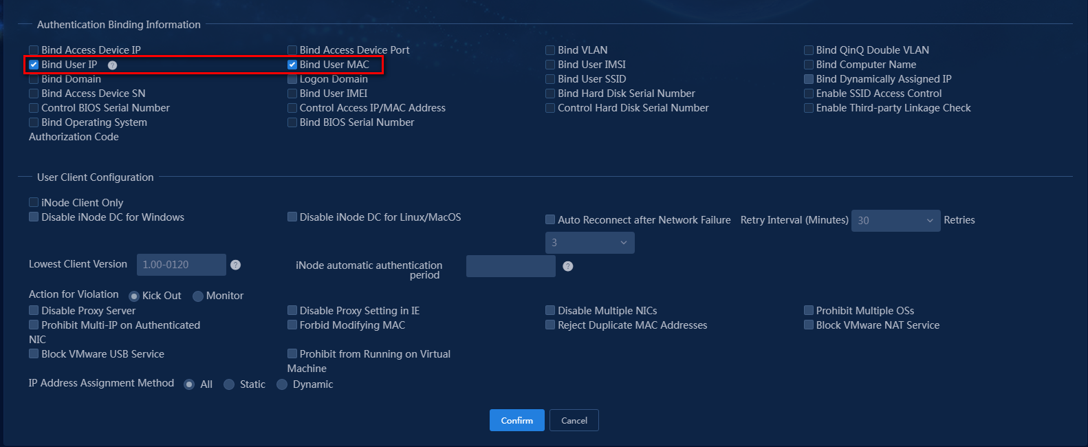
For PC binding, you can enable binding authentication information including the user IP address, user MAC address, and computer name. In this example, configure the access policy to bind the user IP address and MAC address.
To add an access policy:
1. On the top navigation bar, click Automation.
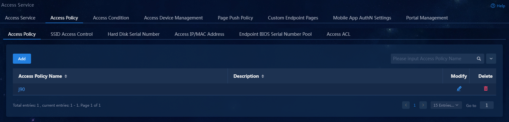
2. From the left navigation pane, select User > Access Service > Access Policy.
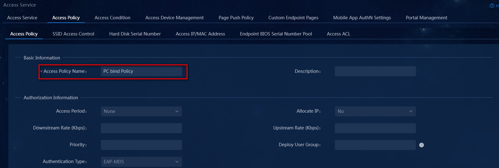
3. Click Add to access the page for adding a Access policy.
a. In the Basic Information area, enter the name of the access policy and select the service group to which the policy belongs.
b. In the Authentication Information area, select the Bind User IP and Bind User MAC options.
c. Use the default settings for other parameters.
The configuration result is as shown in Figure 8.
Figure 8 Adding an access policy
4. Click Confirm. The system returns to the Access Policy page. You can view the newly added access policy in the list.
Adding an access service
An access service is a collection of policies for user authentication and authorization. This example only requires PC binding access control for users.
To add an access service:
1. On the top navigation bar, click Automation.
2. From the navigation pane, select User > Access Service.

3. Click Add.
Figure 10 Adding an access service
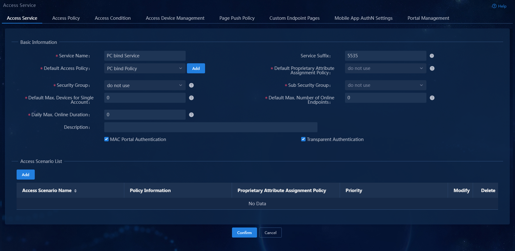
4. Configure the basic parameters for the access service:
¡ Service Name: Enter a service name. Make sure the name is unique on the EIA server.
¡ Service Suffix: Enter a service suffix, which identifies the name of the domain to be used for user authentication. The service suffix, authentication username, authentication domain, and the device's RADIUS scheme command are closely related to each other. For more information about the matrix of these elements, see Table 1.
¡ Default Access Policy: Specify an access policy as the default access policy.
¡ Use the default settings for other parameters.
|
Authentication username |
Authentication domain on the device |
RADIUS scheme command on the device |
Service suffix on EIA |
|
X@Y |
Y |
user-name-format with-domain |
Y |
|
user-name-format without-domain |
No suffix |
||
|
X |
[Default Domain] Default domain on the device |
user-name-format with-domain |
[Default Domain] |
|
user-name-format without-domain |
No suffix |
5. Click Confirm. The system returns to the Access Service page. You can view the newly added access service in the list.
Access user
An access user is the identity used when a user accesses the network, including information such as account name, password, and access services used.
To add an access user:
1. On the top navigation bar, click Automation.
2. From the left navigation pane, select User > Access User.
3. Click Add.
Figure 12 Adding an access user
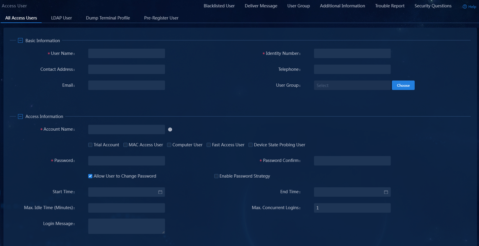
4. Configure basic information, access information, and access services:
¡ User Name and Identity Number: The name and ID of the user.
¡ Account Name: Specify an account name to uniquely identify the access user.
¡ Password/Password Confirm: Enter the password for authentication and enter the password again for confirmation.
¡ Access Service: Select the previously added access service.
¡ Use the default settings for other parameters.
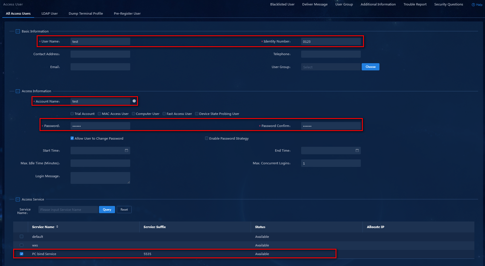
Configure the access user as shown in Figure 13.
Figure 13 Access user configuration information
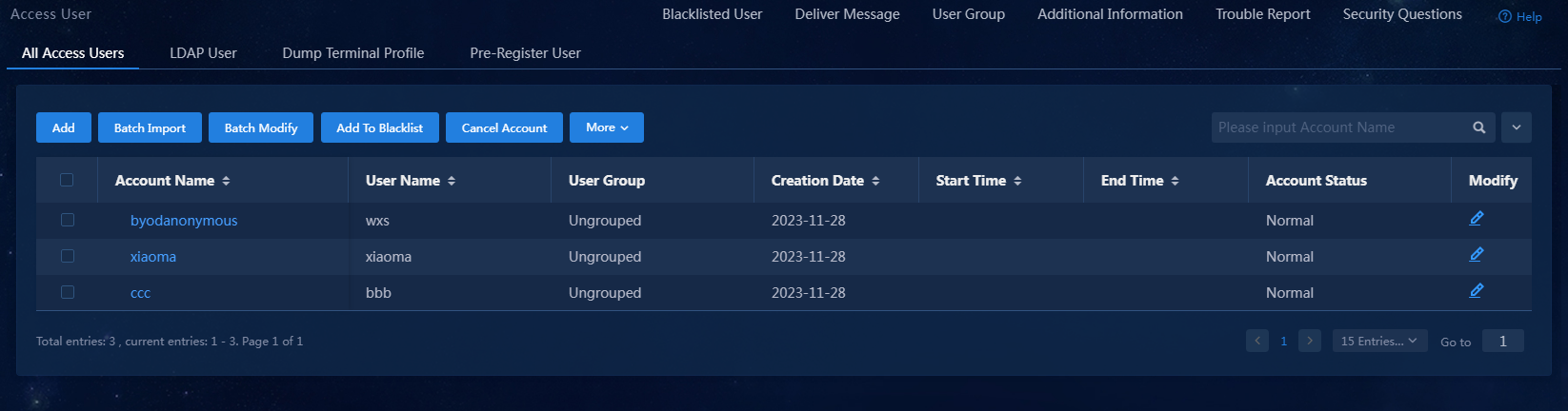
5. Click Confirm. Verify that the access user has been added to the access user list.
Figure 14 Viewing the newly added access user
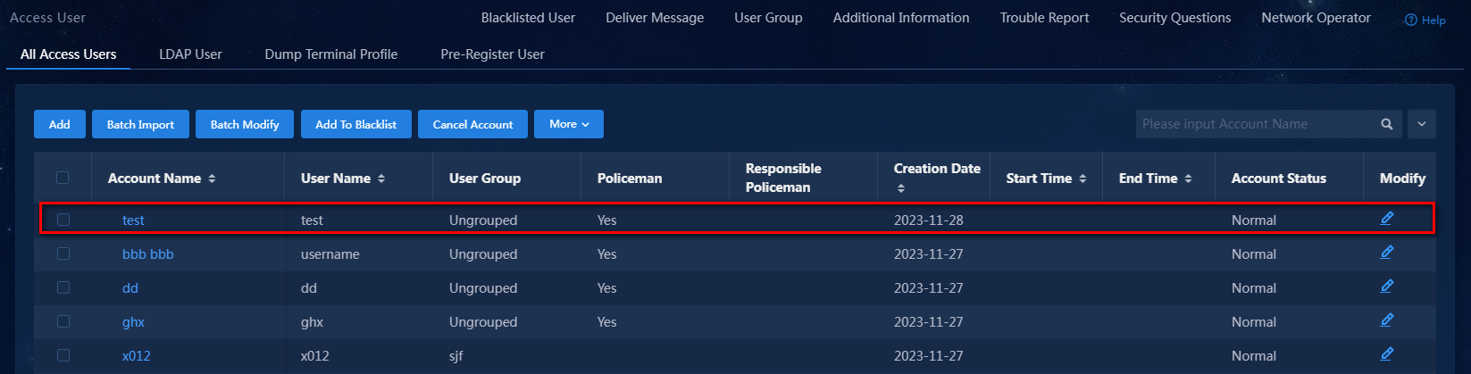
In the access user list, click the account name link to view detailed information about the access user. Verify that the endpoint IP address and MAC address are left empty for the newly added access user, as shown in Figure 15.
Figure 15 Viewing detailed information about the newly added access user

Configure the access device
The access device is used to control user access. Authenticated users can access the network, while unauthenticated users cannot access the network.
As a best practice to configure the access device, perform the following tasks in order:
3. Enabling 802.1X authentication
In this example, log in to the access device through Telnet from the Windows CLI and configure it.
Creating a RADIUS scheme
<Device>system-view
# Configure RADIUS scheme pcbind. # Specify the EIA server as the authentication and accounting server. Configure the authentication port, accounting port, and shared key as those configured on EIA, as described in "Adding an access device."
[Device]radius scheme pcbind
New RADIUS scheme
[Device-radius-pcbind]primary authentication 192.168.7.196 1812
[Device-radius-pcbind]primary accounting 192.168.7.196 1813
[Device-radius-pcbind]key authentication simple expert
[Device-radius-pcbind]key accounting simple expert
# Include domain names in the usernames sent to the RADIUS server. For more information, see Table 1.
[Device-radius-pcbind]user-name-format with-domain
[Device-radius-pcbind]quit
Creating a domain
# According to Table 1, configure a domain name the same as the service suffix configured in "Adding an access service."
[Device]domain 5535
# Configure the domain to use RADIUS scheme pcbind for authentication, authorization, and accounting.
[Device-isp-5535]authentication lan-access radius-scheme pcbind
[Device-isp-5535]authorization lan-access radius-scheme pcbind
[Device-isp-5535]accounting lan-access radius-scheme pcbind
[Device-isp-5535]quit
Enabling 802.1X authentication
# Enable 802.1X both globally and on GigabitEthernet 1/0/39. For 802.1X authentication to take effect, you must enable it both globally and on the interface that users access.
[Device]dot1x
[Device] interface GigabitEthernet 1/0/39
[H3C-GigabitEthernet 1/0/39]dot1x
[H3C-GigabitEthernet 1/0/39]quit
# Set an 802.1X authentication method. Supported 802.1X authentication methods include PAP, CHAP, and EAP. To perform certificate-based authentication, you must set the authentication method to EAP.
[Device]dot1x authentication-method chap
Verifying the configuration
Use the iNode client to access the network through 802.1X authentication. If the authentication is successfully passed, the configuration is correct. If the authentication fails, the configuration is incorrect.
Installing the iNode client
Install the iNode client with 802.1X connection function.
|
|
NOTE: EIA supports all versions of iNode. You can select an iNode version as needed. |
Using the iNode client for 802.1X authentication
1. Open the iNode PC client, and select 802.1X connection.
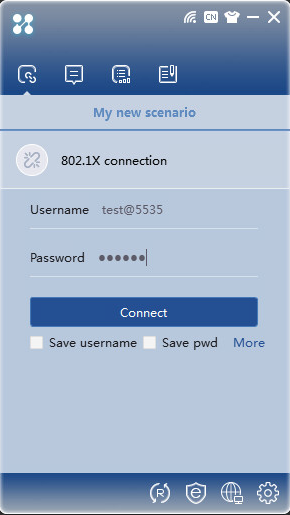
2. Entering the correct username and password, and then click Connect. Once authenticated, you can view online users on the Online User page of EIA.
|
|
NOTE: To make sure that EIA can obtain the IP address of the iNode client, select the Upload IPv4 address/Upload IPv6 address option in the properties of the 802.1X connection. |
Viewing online users on EIA
On the top navigation bar, click Monitor. From the left navigation pane, select Monitor List > Online User.
Viewing the endpoint binding information of the access user
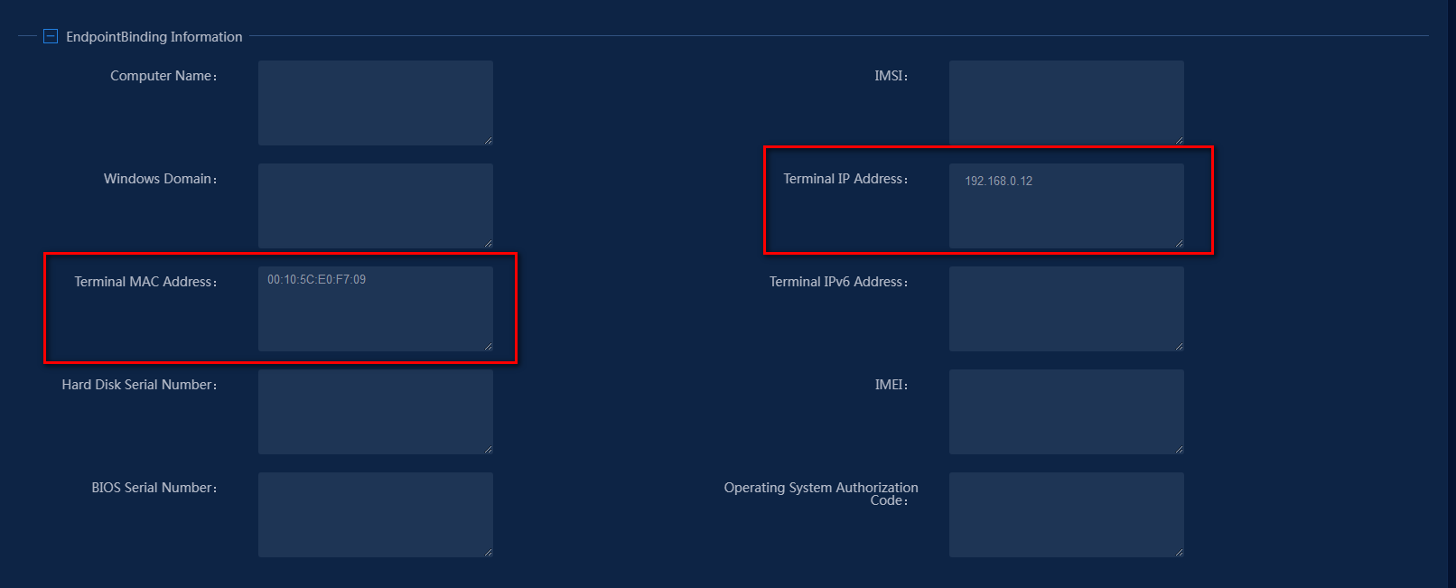
After successful authentication, EIA learns the IP address and MAC address bound to the endpoint. Verify that the endpoint's IP address and MAC address are displayed in the endpoint binding information of the access user, as shown in Figure 17.
Figure 17 Viewing the endpoint binding information of the access user
Authentication failure upon unmatched binding information (using IP address as an example)
After successful authentication, if you change the IP address of the endpoint and authenticate again, authentication fails. iNode client prompts that the static IP address binding check has failed.
The failure is because that the IP address of the access user has changed and is inconsistent with the endpoint IP address bound to the access user in the EIA server.
