Country / Region
- Products and Solutions
- Industry Solutions
- Services
- Support
- Training & Certification
- Partners
- About Us
- Contact Sales
- Become a Partner
-
 Login
Login
Country / Region
MDC White Paper
Copyright © 2018 New H3C Technologies Co., Ltd. All rights reserved. No part of this manual may be reproduced or transmitted in any form or by any means without prior written consent of New H3C Technologies Co., Ltd. The information in this document is subject to change without notice. |
|
Contents
Default MDC and non-default MDC
Layer 2 forwarding within an MDC
Layer 3 forwarding within an MDC
Overview
Technical background
With the deployment of server virtualization technologies in data centers, requirements for network device virtualization emerged. For example, a company has added a new department. You can build background applications by configuring servers and deploy network devices for the department. Deploying new network devices increases the budget. To cut down the budget, you can use the Multitenant Device Context (MDC) technology to create a virtual network device on a deployed physical device.
The MDC technology is a 1:N virtualization technology. It can virtualize a physical network device or an IRF fabric into multiple logical network devices called MDCs. It virtualizes the control plane, the data plane, and the management plane. It supports independent starting and running of processes within each MDC. All MDCs on a physical device share the same kernel, but each MDC has its separate data space. Each MDC operates and provides services like a standalone physical device.
MDC provides hardware resource virtualization. It supports authorizing MDCs to use interface cards, assigning physical interfaces to MDCs, and limiting resource usages of MDCs by specifying CPU weights, memory space quotas, and disk space percentages. This makes MDCs very much like standalone physical devices.
An MDC functions as a physical device and has separate software environment, data, and hardware resources. In addition, you can reboot an individual MDC without affecting the operation of other MDCs in the same physical device.
Benefits
MDC provides the following benefits:
Sharing—MDCs on a physical device share the physical resources of the physical device. This improves the efficiency of the physical resources.
Isolation—MDCs are isolated from each other. Each MDC forwards network data by using only the interfaces assigned to it. An MDC has its own resources.
Control plane that enables independent routing calculation within the MDC.
Layer 2, Layer 3, and MPLS forwarding entries.
Management plane that enables independent user rights control.
Easy management—On the physical device (the default MDC), you can create, start, stop, and delete non-default MDCs. From the default MDC, you can log in to any non-default MDC to manage the non-default MDC. You can also remotely log in to a non-default MDC to manage it.
MDC implementation
Concepts
MDC achieves the following objectives:
Realizes virtualization on the network service level, and the per-MDC services give users the feeling that the MDCs are separated devices.
Enables users to adjust and allocate hardware resources among MDCs to improve resource efficiency.
Enables the device administrator to manage and maintain non-service level resources only in the default MDC without virtualizing them.
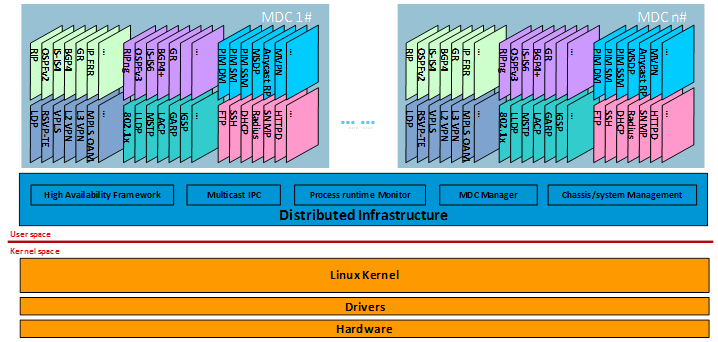
Figure 1 shows the MDC software architecture. The modular architecture of the Comware V7 platform ensures that the processes run on a per-MDC basis. The control planes of MDCs are completely isolated and run independently.
The Comware V7 platform uses the operating system-level virtualization technology, which simulates multiple containers for running applications. The operating-system level managements, such as process management, memory management, and disk management, are virtualized on per-MDC basis.
Compared with the 1:N virtualization technologies Hypervisor and Bare-metal, MDC enables all MDCs to share the kernel, has the best management performances in operating system virtualization, and consumes less resources.
Figure 1 Modular architecture of Comware V7
MDCs on a distributed device
A typical distributed device (including IRF fabrics) has multiple MPUs and multiple interface cards. After you create MDCs on the device, each interface card must support operating of multiple MDCs, depending on how you assign interface cards and interfaces to the MDCs. When you create/start an MDC, the MDC is created/started on every MPU.
When you create MDCs, the system creates a virtual context for each MDC on each MPU and each interface card that the MDC is authorized to use. Each virtual context is called an MDC-OS, as shown in Figure 2. An MDC-OS contains all processes and data used to support the MDC on the card. All MDC-OSes of an MDC constitute the MDC.
Figure 2 MDCs on a distributed device
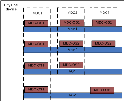
When you log in to an MDC, you can configure the resources assigned to it. For example, if you log in to MDC 1, you can configure and manage the interface cards with MDC-OS1s. Data synchronization between the MDC-OSes of an MDC occurs only on the MPUs and the interface cards that the MDC is authorized to use. Other cards are not affected.
You can stop an MDC on an interface card at the CLI. Then, the MDC has only non-virtual processes running on the card and has only a little data to synchronize.
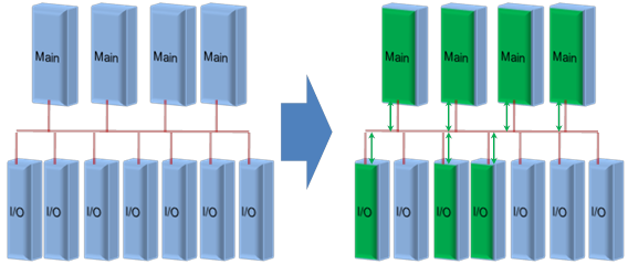
As shown in Figure 3, data is synchronized among the interface cards assigned to the same MDC. You can assign an interface card to only one MDC, and the resources on this interface card belong to this MDC. In this way, the interface card has the same specifications as provided when the device operates independently.
Figure 3 MDC data synchronization
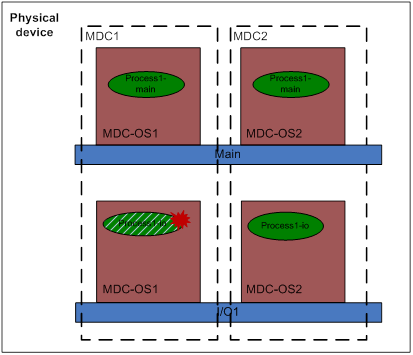
On an interface card, the processes and data of an MDC are isolated from those of other MDCs. As shown in Figure 4, if process 1-io is restarted to recover from a failure, process 1-io of MDC 2 is not affected. After you assign CPU weights to MDCs, when process 1-io of MDC 1 has a high CPU requirement, process 1-io is not affected.
Figure 4 Process virtualization on interface cards
MDC functions
Default MDC and non-default MDC
A device supporting the MDC technology is an MDC itself, and is called the "default MDC." The default MDC always uses the name Admin and the ID 1. You cannot delete it or change its name or ID.
When you log in to the physical device, you are logged in to the default MDC. To configure the physical device is to configure the default MDC.
From the default MDC, you can manage the whole physical device, create and delete non-default MDCs, and assign interface, CPU, storage space (Flash and CF card), and memory space resources to non-default MDCs.
No MDCs can be created on a non-default MDC. Administrators of non-default MDCs can only manage and maintain their respective MDCs.
A non-default MDC can use only the resources assigned to it. It cannot use the resources assigned to other MDCs or the remaining resources on the physical device. Resources that are not assigned to any non-default MDC belong to the default MDC.
MDC management
There are four types of MDC management operations: creating MDCs, starting MDCs, stopping MDCs, and deleting MDCs. Only an administrator with the network-admin role can perform MDC management operations.
Creating an MDC
Creating an MDC is to use some resources on the device to construct a logical device. Immediately after being created, a non-default MDC is not started and is placed in inactive state. You can allocate resources for it, but cannot switch to or log in to it.
Once you assign resources to a non-default MDC, the default MDC cannot use the resources anymore.
Starting an MDC
Starting an MDC is to "power on" the logical device. An MDC must be started to operate. A started non-default MDC is in active state and is ready to provide services. You can switch to it from the default MDC or log in to it remotely to configure it.
The start process of an MDC is similar to that of a physical device. When you start an MDC, the device starts the MDC's MDC-OSes, initiates its processes, restores its configuration, and enables its interfaces. After startup, the MDC uses the resources assigned to it to operate. To revoke resources assigned to a started MDC, make sure the MDC does not use the resources anymore.
Stopping an MDC
Stopping an MDC places the MDC to inactive state, deletes all its MDC-OSes, and disables its processes from providing services, but does not release the resources assigned to it. Stopping an MDC is equivalent to "power off" the logical device. A stopped MDC can be re-started.
You can only stop an MDC that is already started.
Deleting an MDC
After being deleted, an MDC does not exist anymore, and all resources assigned to it were returned to the default MDC.
You can delete an MDC in active or inactive state. Deleting an MDC in active state equals stopping the MDC and then deleting the MDC.
Resource Allocation
Only an administrator of the default MDC who has the network-admin user role can allocate resources for non-default MDCs. The resources that can be allocated include:
Interface cards
An interface card can support multiple MDCs. You can use the location slot command to authorize multiple MDCs to use the same interface card. If you authorize an inactive MDC to use an interface card, the device creates an MDC-OS for the MDC on the interface card, but does not start the MDC-OS. If you authorize an active MDC to use an interface card, the device creates an MDC-OS for the MDC on the interface card and starts the MDC-OS. After being started, an MDC uses the interfaces assigned to it to provide services.
By default, the default MDC is started on all interface cards. If you assign all resources on an interface card to a non-default MDC, however, you must stop the default MDC on the interface card. As a result, the default MDC has only non-virtual processes running on the interface card and occupies a little CPU and memory resources.
Interfaces
Interfaces are the most important resources. You can use the allocate interface command to assign interfaces to non-default MDCs. If possible, assign interfaces to an MDC when the MDC is inactive to reduce frequent system changes. When you assign an interface to an MDC, the device restores the default settings of the interface and reconfigures the interface for the MDC.
CPU weights
Use the limit-resource cpu weight command to assign CPU weights to non-default MDCs. The setting for an MDC takes effect on all cards where the MDC's MDC-OSes run. MDCs share and compete for CPU resources. If an MDC needs a lot of CPU resources while the other MDCs are relatively idle, the MDC can get more CPU weights. If all MDCs need a lot of CPU weights, the device assigns CPU resources to MDCs according to their CPU weights.
Memory space
By default, a non-default MDC share the memory space with other MDCs and can use all free memory space. You can use the limit-resource memory command to limit the amount of memory space that each MDC can use, including the default MDC.
Disk space
When an MDC is created, the device creates a directory for the MDC on the storage medium to save the MDC's files, such as configuration files and log files. By default, MDCs on a device share and compete for the device’s storage space. You can use the limit-resource disk command to assign disk space percentages to MDCs.
Layer 2 forwarding within an MDC
Each MDC has its own Layer 2 ports, MAC address entries, and VLAN resources. As shown in Figure 5, Layer 2 ports P1 and P2 belong to MDC A and MDC B, respectively.
VLANs on different MDCs can use the same VLAN ID. For example, both MDC A and MDC B can have a "VLAN 2."
If you connect a PC with the MAC address MACA to P1 and P2, two MAC address entries are created.
Because P1 belongs to MDC A, the MAC address entry MACA-VLAN2-P1 is created for MDC A on the interface card. The entry is then synchronized to all the other interface cards where the other ports in the same VLAN of MDC A reside.
Because P2 belongs to MDC B, the MAC address entry MACA-VLAN2-P2 is created for MDC B on the interface card. The entry is then synchronized to all the other interface cards where the other ports in the same VLAN of MDC A reside.
The two entries are independent of each other.
Figure 5 Layer 2 forwarding within an MDC
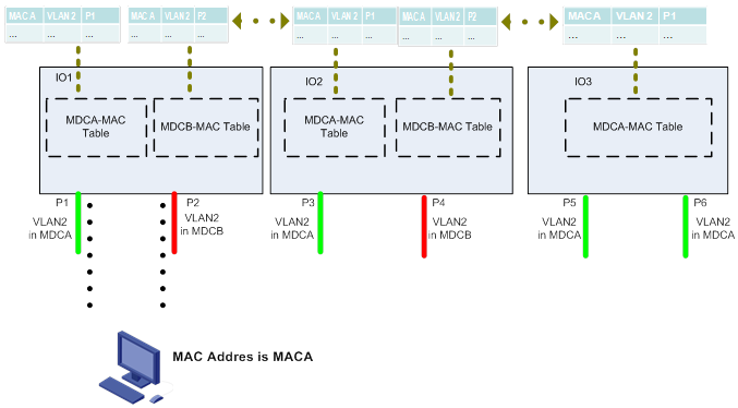
If an interface card is assigned to only one MDC, the maximum number of MAC address entries the interface card can learn equals that the physical device can learn.
Layer 2 protocols, such as MSTP and LACP support virtualization. They determine that each MDC is a standalone device and assign different MDCs different bridge MAC addresses for MSTP calculation. LACP aggregation cannot occur across two MDCs because they are considered different devices.
Layer 3 forwarding within an MDC
An MDC supports multiple VPN instances. The maximum number of VPN instances that a device can support equals the maximum number of MDCs the device supports multiplied by the maximum number of VPN instances the device supports.
Figure 6 Layer 3 forwarding with an MDC
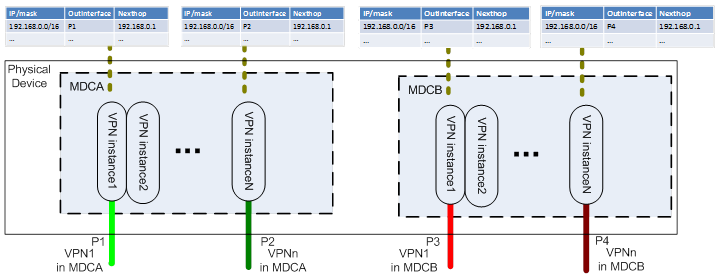
As shown in Figure 6, VPN instances on different MDCs can use the same VPN instance number. In different VPN instances, there can be the same private IP addresses.
Each VPN on an MDC maintains its own Layer 3 FIB entries.
When a packet arrives at a port, the device first examines to which MDC the port belongs and to which VPN the port belongs. Then, the device searches the FIB. If a matching entry is found, the device forwards the packet based on the entry.
Rational allocation of resources among MDCs makes entries isolated and each MDC get more entries, which equals to enlarging the specifications of the physical device.
Figure 7 FIB entry specifications among MDCs
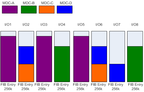
As shown in Figure 7, MDC-A and MDC-B have more Layer 3 applications, and therefore have more FIB entries. A good practice is to deploy a separate interface card for each of them so they can use the FIB entry space exclusively. MDC-D needs more Layer-3 forwarding entries. Query FIB entry specifications and you can find out that there are more available FIB entries on interface cards IO2, IO6, and IO7, then you can assign these interface cards to MCD-D.
Non-default MDC management
Login channels
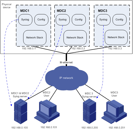
When a non-default MDC is created, the system automatically creates a management interface for the MDC. The management interfaces of all non-default MDCs use the same type and number and the same physical port and link as that of the default MDC, but they have different MAC addresses and you must assign them different IP addresses so administrators of different MDCs can access and manage their respective MDCs through the management interfaces.
As shown in Figure 8, the user of MDC 2 manages MDC 2 by establishing a connection through the virtual management interface of MDC 2.
Figure 8 Virtualized network management channels
Management methods
As shown in Figure 8, each MDC has a separate configuration module, provides a separate CLI and a separate Web interface, and supports SNMP access. Administrators of an MDC can access the MDC through the virtual Ethernet management interface of the MDC.
The syntaxes and execution effects of commands provided by an MDC are the same as those provided by a standalone device.
Syslog output
As shown in Figure 8, each MDC outputs its own syslog information. You can configure MDCs to output their syslog information to the same syslog server or different syslog servers.
Upon a device-level change, such as installation, removal, or restart of an MPU, a piece of syslog information is created on each MDC.
When logged in to the default MDC, you can view only syslog information generated on the default MDC. To view the syslog information generated on a non-default MDC, you must switch to the non-default MDC first.
Configuration file
Each MDC has its own configuration files. Saving and restoring configuration on an MDC does not affect other MDCs. An administrator of an MDC can restart only the MDC. After a reboot, the MDC retrieves its own configuration. Resource allocation commands performed on the default MDC affects the involved non-default MDCs. Before revoking resources from a non-default MDC, make sure the MDC is not using the resources.
User role management
Comware V7 manages user rights based on user-roles. After you assign user roles to a user, the user can execute only commands allowed by the user roles.
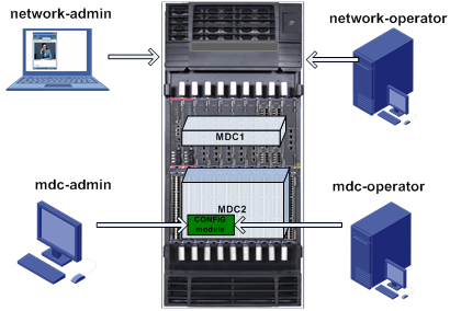
As shown in Figure 9, an MDC-capable device provides four user roles, which fall into two levels:
Physical device level
network-admin—Manages all functions and resources of the device, and creates or deletes MDCs.
network-operator—Displays the operation of all functions and the usage of all resources, switches from the default MDC to a non-default MDC, and displays the resources on the MDC.
MDC level
mdc-admin—Manages all functions and resources of the MDC. This user role does not provide the right to create/delete MDCs or switch to another MDC.
mdc-operator—Displays the operation of all functions and the usage of all resources on the MDC.
A non-default MDC supports only the two MDC-level user roles, and operations of a login user is effective only for the MDC itself. Other MDCs are not affected.
Each MDC can add its own users. The administrator of an MDC can log in to and manage only this MDC. The management and configuration of an MDC does not affect any other MDCs. This simplifies the management environment and reduces the difficulty of maintenance.
IRF-based MDC
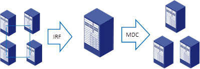
IRF is an N:1 virtualization technology that virtualizes multiple devices into one logical fabric.
Comware V7 supports implementing MDCs on an IRF fabric. You can first merge multiple physical devices into one IRF fabric, and then virtualize the IRF fabric into multiple MDCs.
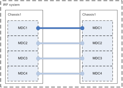
As shown in Figure 10, connect and configure the four devices to set up an IRF fabric. Then, create three MDCs in the IRF fabric. You can allocate all physical resources of IRF member devices among the MDCs.
You can assign interface cards of different physical devices to the same MDC. Packets from one interface card in one chassis are sent to the same MDC in another chassis through IRF links, just like they are forwarded on one physical device.
Advantages
IRF-based MDC provides the following advantages:
High device efficiency—IRF-based MDC allows you to integrate device resources to the maximum extent and virtualize the devices into MDCs as required.
High system availability—Using both virtualization technologies together, you can obtain benefits of both technologies. For example, IRF-based MDC enables each MDC to get the 1:N redundancy protection.
High system expandability and resiliency—You can add more ports, more bandwidth, and more processing capability to the IRF fabric, increasing the capabilities of IRF-based MDCs without changing the network deployment. To deploy MDCs in an IRF application scenario, you can configure MDCs on the IRF fabric, without affecting existing networks or redeploying the existing networks.
Deployment considerations
Cross-chassis traffic of MDCs brings great pressure to the IRF link between the chassis. To balance cross-chassis traffic, you can deploy multiple IRF links between chassis and allocate IRF links on a per-MDC-basis. As shown in Figure 11, MDC 1 is the default MDC. The IRF link of MDC 1 carries both data packets and control packets, while those of non-default MDCs carry only their respective data packets.
Figure 11 MDCs in an IRF fabric
High availability and ISSU
High availability of MDC internal processes
Comware V7 uses the graceful restart technology to implement high availability of processes. A process regularly backs up its runtime data. When it restarts, the relevant software and hardware keep the process's runtime data. After startup, the process can restore its runtime data and communicate with the relevant software and hardware to synchronize its runtime data. The process cannot provide services for new users only during the reboot time. As soon as the process restarts up, the process provides services correctly. During the reboot time, other processes in the MDC provide services without being affected.
For a process-based service, an MDC starts an active process on the active MPU and one standby process on each standby MPU. Each MDC has a separate, build-in high-availability control policy. When an active/standby switchover occurs on an MDC, processes of other MDCs are not affected.
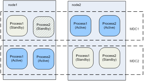
As shown in Figure 12 and Figure 13, the active and standby processes run on per-MDC basis. The active process 1 of MDC 1 is on node 2, and the active process 1 of MDC 2 is on node 1. An active/standby switchover for process 2 of MDC 1 does not affect the active and standby processes of MDC 2.
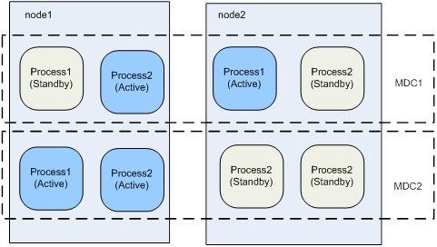
Figure 13 Processes after an active/standby switchover
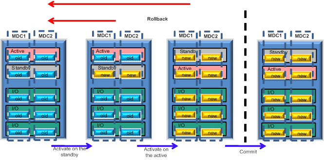
ISSU for MDCs
All MDCs of the same physical device run the same copy of startup software. Software upgrade takes place only on the default MDC As shown in Figure 14, all non-default MDCs are upgraded after the default MDC is upgraded.