Country / Region
- Products and Solutions
- Industry Solutions
- Services
- Support
- Training & Certification
- Partners
- About Us
- Contact Sales
- Become a Partner
-
 Login
Login
Country / Region
EVB Technology White Paper
Copyright © 2018 New H3C Technologies Co., Ltd. All rights reserved. No part of this manual may be reproduced or transmitted in any form or by any means without prior written consent of New H3C Technologies Co., Ltd. The information in this document is subject to change without notice. |
|
Contents
Overview
Edge Virtual Bridging (EVB) is an automatic network deployment technology that applies to data centers. It simplifies traffic forwarding, controls network switching, traffic management, and policy deployment for virtual machines (VMs), and automatically migrates network control and management policies upon a VM migration.
Physical switches and servers used in EVB are called EVB bridges and EVB stations. This document describes EVB implementation on bridges.
Technical background
The fast expansion of data centers brings management problems. Data center virtualization solves these problems by improving resource efficiency (such as CPU utilization and storage capacity), decreasing system power consumption, and reducing design, operation, management, and maintenance costs.
Data center virtualization includes network virtualization, storage virtualization, and server virtualization. Server virtualization uses specific virtualization software such as VMware to create VMs on a single physical server. As shown in Figure 1, each VM operates independently and has its own operating system, applications, and virtual hardware environments.
Figure 1 Server virtualization
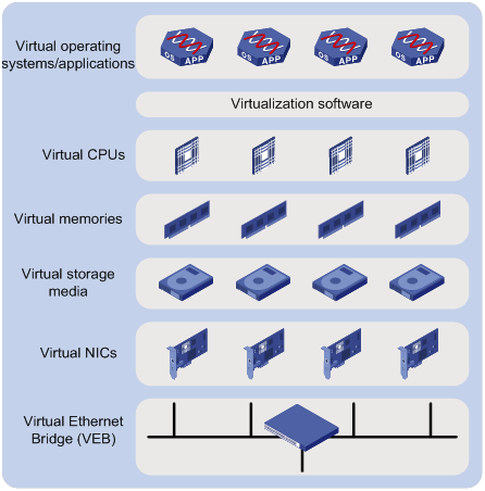
VMs on a physical server communicate with each other or with the external network through a Virtual Ethernet Bridge (VEB). VEBs are implemented through software or hardware such as NICs. Both implementation methods have the following limitations:
Lack of traffic monitoring capabilities such as packet statistics collection, traffic mirroring, and NetStream.
Lack of network policy enforcement capabilities, such as QoS.
Lack of management scalability, especially in unified deployment of the internal network and the external switching network.
EVB solves these limitations. It uses an EVB bridge to switch traffic for VMs on a directly connected EVB station. EVB implements traffic monitoring, network policy enforcement, and unified network deployment and management for VMs.
Benefits
EVB provides the following benefits:
Reducing the station's CPU and memory utilization.
Unified deployment and management of internal and external networks.
Separation of VM network service policies and VM location. A policy server controls network service policies for VMs in the entire network, so the policies can be automatically re-deployed when a VM migration occurs.
EVB implementation
Concepts
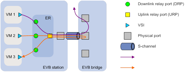
Figure 2 shows the components on the EVB station and EVB bridge.
ER
An Edge Relay (ER) (the Virtual Ethernet Bridge in Figure 1) resides on the server side, and forwards traffic for the physical server. An ER has one or multiple DRPs and one URP. Both the URP and DRPs are called ER ports.
ERs are implemented through software or hardware, and can operate in VEB mode or VEPA mode.
RR mode
Reflective Relay (RR) mode, also called hair-pin mode, is an operation mode in which a received frame on a port that supports this function can be forwarded out of the same port. As shown in Figure 2, the EVB bridge uses this mode to forward traffic among VMs on an EVB station.
The RR mode is not supported by traditional switches, which means a frame cannot be forwarded out of the same port on which it is received to avoid loops.
If the RR mode is supported on an EVB bridge, traffic among VMs on an EVB station can be forwarded by the EVB bridge through physical ports or an S-channel of a physical port.
VEB
VEB, one type of ER operations, requires RR mode to be disabled on the EVB bridge port. In a VEB ER implementation, the Virtual Ethernet Bridge can forward traffic among VMs in the same EVB station, and the EVB bridge forwards traffic between VMs and the external network.
VEB provides the traffic bridging function, and has the same limitations as the Virtual Ethernet Bridge as described in "Technical background."
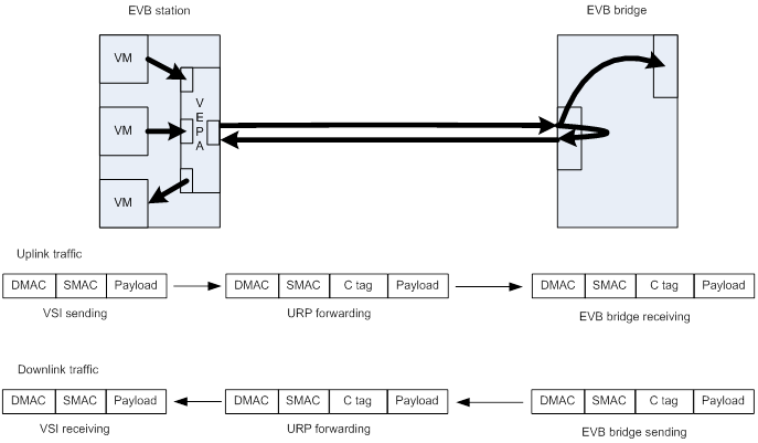
VEPA
VEPA, another type of ER operations, requires the RR mode to be enabled on the EVB bridge port. It forwards all traffic, including traffic among VMs in an EVB station through its URP. VEPA facilitates traffic control and management, and policy deployment and application of the entire network because the server does not consume many resources and traffic switching is handled by the EVB bridge.
A VEPA has a URP and a DRP. The URP connects to the EVB bridge, and the DRP connects to the virtual NIC of the corresponding VM. VEPA directly forwards frames received on a DRP to the URP, but first searches the forwarding table for the destination MAC first for frames received on a URP.
The VM MAC learning mechanism for VEPA is beyond the scope of this document.
VEPA does not change the frame format when forwarding frames.
Figure 3 VEPA mechanism
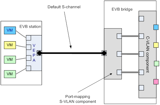
S-channel
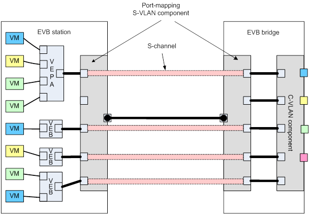
A physical server might require multiple ERs. To separate traffic on a physical port, EVB uses a point-to-point S-VLAN established between a Port-mapping S-VLAN component in an EVB station and a Port-mapping S-VLAN component in an EVB bridge. Such an S-VLAN is called an S-channel.
An S-channel is identified by the S-VLAN Identifier (SVID) and the S-channel Identifier (SCID), and the two values together are called an (SCID, SVID) pair. On an EVB station, an S-channel corresponds to the URP of an ER. On an EVB bridge, the end point of an S-channel is known as an S-channel interface.
EVB uses CDCP to establish an S-channel, and exchanges EVB TLVs to negotiate EVB capabilities such as RR and other parameters for the S-channel.
Figure 4 S-channel architecture overview
EVB can be implemented no matter whether both the EVB station and EVB bridge support S-channels or only the EVB bridge supports S-channels.
Supported by both the EVB station and EVB bridge
The S-VLAN component in the EVB station adds an S-tag upon receiving the uplink traffic, and the EVB bridge removes the S-tag when it forwards the traffic to the external network. The S-VLAN component in the EVB bridge adds an S-tag when receiving the downlink traffic, and the S-VLAN component in the EVB station removes the S-tag when the traffic leaves the station.
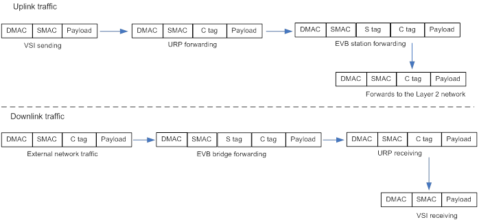
Supported only by the EVB bridge
If the EVB station requires only one ER to forward VM traffic, the EVB station does not necessarily need to support the S-VLAN component, so an S-channel is unnecessary either. When the EVB station connects to the EVB bridge that supports S-channels, the EVB bridge considers the traffic from the default S-channel, and does not change the frame format.
Figure 6 S-channel supported only by EVB bridge
S-channel interface
An S-channel interface is a virtual end point of an S-channel on an EVB bridge. Each S-channel interface associates with an S-channel on a physical port on the bridge to differentiate and handle traffic for different S-channels from the station.
An S-channel interface is a subchannel of an Ethernet port with EVB enabled. An S-channel interface ID is in the format of X/Y/Z: m, where X represents the slot number of the card where the interface resides, Y represents the subslot number of the subcard, Z represents the number of the physical port, and m represents an S-channel ID. An S-channel ID is the same as the S-channel ID that the station requests, and the S-VLAN ID associated with an S-channel interface is assigned by the bridge. For example, a station sends a CDCP request to apply for S-channel 5, with the (SCID, SVID) pair as (5, 0) in the TLV. The bridge assigns an S-channel with SVID 10 based on the current SVID usage, and replies a CDCP TLV with (5, 10).
Also, the station sends a CDCP request to delete an S-channel interface by removing the (SCID, SVID) pair from the CDCP TLV. The bridge deletes the S-channel interface upon receiving the TLV.
You can manually create or delete an S-channel interface by specifying the SCID and SVID of the corresponding S-channel.
A bridge automatically creates a default S-channel interface for an EVB-enabled port, without negotiating with the station. When EVB is enabled on an Ethernet port, a default S-channel interface is automatically created, and the default interface is deleted only after EVB is disabled on the Ethernet port. In EVB, the (SCID, SVID) pair for a default S-channel interface must be (1, 1).
VSI
A Virtual Station Interface (VSI), which can be considered an interface of a virtual NIC on a VM, directly connects to the DRP of an ER.
A VSI is associated with a logical entity called VSI instance, which is identified by the VSI Instance Identifier (VSIID). A VSI is associated with a virtual interface called VSI interface on the EVB bridge port to implement VM traffic management and policy configuration.
A VSI interface is a subinterface of an S-channel interface, in the format of X/Y/Z:m.n. X/Y/Z:m indicates an S-channel interface ID, and n represents a VSI interface ID that is assigned by the bridge.
If the station sends a VDP associate or pre-associate request to the bridge, the bridge sends the request and suggested VSI interface ID (the value of n) to the VSI manager. The VSI manager notifies the bridge to create the VSI interface and applies the management or traffic control policies to the VSI interface.
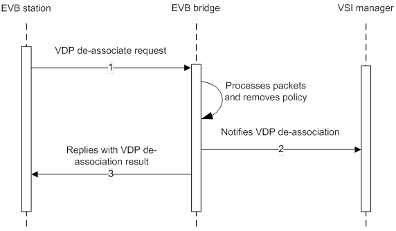
If the station sends a VDP de-associate request to the bridge, the bridge deletes the VSI interface, and informs the VSI manager the VM is successfully removed.
VSI filters
A VSI filter identifies VSI traffic for a VM. EVB supports the following filter info formats:
VLAN ID
VLAN ID + MAC
Group ID + VLAN ID
Group ID + VLAN ID + MAC
MAC must be a valid unicast MAC address. VLAN ID in the range of 1 to 4094 is a valid C-VLAN ID. Group ID classifies VLAN IDs. When the number of VLANs is bigger than 4095, Group ID and VLAN ID together identify a VLAN.
An EVB bridge must use the VSI filter to identify VSI traffic on a VM to apply management or control policies to VSIs.
One VSI can have multiple VSI filters, which are mutually exclusive. For example, a VSI is not allowed to have the same VLAN ID both in the format of VLAN ID and in the format of VLAN ID + MAC.
Protocol mechanism
CDCP
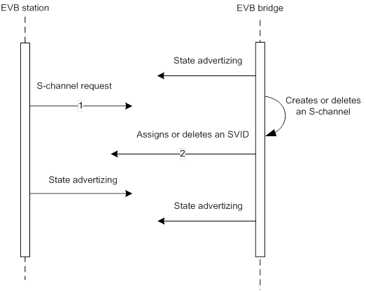
EVB uses the S-Channel Discovery and Configuration Protocol (CDCP) to configure an S-channel between an EVB station and EVB bridge. When a station creates or deletes an S-channel, CDCP sends a CDCP TLV in an LLDP packet that is addressed using the Nearest non-TPMR Bridge address to the bridge. The bridge creates or deletes the S-channel.
Exchange process
As shown in Figure 7, the CDCP exchange process proceeds as follows:
1. The station sends a request (message 1) to the bridge to create an S-channel or delete an existing S-channel.
2. The bridge assigns an SVID or releases the existing SVID, creates or deletes the S-channel interface, and sends a response (message 2) to the station to notify the station of the assigned SVID.
3. The station advertises the current S-channel state in subsequent messages.
Message format
A CDCP TLV contains the fields as shown in Figure 8.
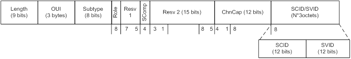
Type—Takes the value of 127.
Subtype—Takes the value of 0x0E.
Role—A value of 1 indicates the sender is operating as a station, and 0 indicates the sender is operating as a bridge.
Resv—Transmitted as zero and ignored on receipt.
SComp—A value of 1 indicates an S-VLAN component is supported, and 0 indicates an S-VLAN component is not supported.
Chncap—Number of S-channels that are supported by the device.
SCID/SVID—SCID indicates the index number of the S-channel, and the default S-channel must be (1, 1). The station assigns up to 167 S-channels, including the default S-channel.
For example, a station sends a CDCP request with an (a, 0) pair to the bridge. If the S-channel is successfully created, the bridge replies with an (a, b) pair, where b is a valid VLAN ID. If the S-channel is not created, the bridge replies with the (a, 0) pair. If the station sends a request in which a valid (SCID, SVID) pair is deleted, the bridge will delete the corresponding S-channel.
EVB TLV negotiation
EVB TLVs are exchanged through LLDP to negotiate EVB capabilities for an S-channel after the S-channel is established, such as RR, ECP parameters, and VDP parameters.
Exchange process
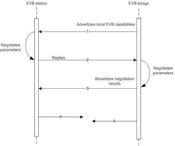
Both a station and bridge can advertise their EVB capabilities to each other. In Figure 9, a bridge advertises its EVB capabilities first. If the station advertises its EVB capabilities first, the TLV exchange process is the same. (Details not shown.)
The EVB TLV exchange uses the following process:
1. The bridge advertises its EVB capabilities by sending a TLV to the station.
2. The station selects an operating value, for example, ECP maximum retries, and sends the larger one of the values configured on the station and bridge in the TLV to the bridge.
3. The bridge compares the remote value and its local value, and sends the larger one in the TLV to advertise the negotiation result.
4. The station and bridge continue to exchange this TLV for maintaining further communications through the S-channel.
Message format
Figure 10 EVB TLV
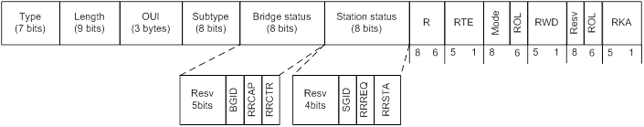
Type—Takes the value of 127.
Subtype—Takes the value of 0x0D.
Bridge status—Includes 3 types of states. For more information, see Table 1.
Field | Value | Description |
BGID | 1 | The EVB bridge controls VID assignment and uses GroupID in VDP exchanges. |
0 | The EVB bridge does not support Group ID in VDP exchanges. | |
RRCAP | 1 | The EVB bridge supports the RR mode. |
0 | The EVB bridge does not support the RR mode. | |
RRCTR | 1 | RR is enabled for the S-channel interface. |
0 | RR is disabled for the S-channel interface. |
Station status—Includes 3 types of states. For more information, see Table 2.
Field | Value | Description |
SGID | 1 | The EVB station supports the use of GroupID in VDP exchanges. |
0 | The EVB station does not support the use of GroupID in VDP exchanges. | |
RRREQ | 1 | The EVB station requests to enable the RR service. |
0 | The EVB station requests to disable the RR service. | |
RRSTAT (2bits) | 11/10 | The EVB station does not know if the EVB bridge supports the RR service. |
01 | RR is enabled on the S-channel. |
R—The value of ECP maximum retries. Both sides use the larger one of the two values of R.
RTE—ECP retransmission exponent. The retransmission timer is calculated as:
10 × 2RTE ms
If neither the station nor the bridge receives an acknowledgement for the ECP request from the other after the retransmission timer expires, the request must be resent. Both sides use the larger one of the two values of RTE for this calculation.
Mode—A value of 1 indicates the device is an EVB bridge, and 2 indicates the device is an EVB station.
ROL + RWD—The exponent value that the station or bridge proposes for determining the value of the VDP resource wait delay variable. On the bridge side, the value is calculated as:
10 × 2RWD μs
ROL flag indicates whether the remote RWD value is in use (takes a value of 1) or the local value is in use (takes a value of 0).
For example, the station sends an EVB TLV, where ROL = 0, RWD = 21. The initial configuration by the bridge is RWD = 20. Upon receiving the request from the station, the bridge sends its EVB TLV, where ROL = 1, RWD = 21.
ROL+RKA—The exponent value in use by the EVB station for determining the value of the VDP Reinit Keep Alive variable. On the bridge side, the value is calculated as:
[ 2RKA + (2 × R + 1) × 2RTE] × 10 μs
ROL flag indicates whether the remote RKA value is in use (takes a value of 1) or the local value is in use (takes a value of 0). (This formula is from draft 1.6, the formula after draft 2.0 is multiplied by 1.5.)
VDP
VSI Discovery and Configuration Protocol (VDP) associates a VSI with a bridge port. When a station creates, deletes, or migrates a VM, it sends a request to the bridge to create or delete a VSI interface on the bridge.
Issued by a station, VDP requests include pre-associate, pre-associate with resource reservation, associate, de-associate. A bridge replies only to a corresponding VDP request.
When a station creates a VM, it sends a VDP pre-associate or associate request to the bridge. A successful pre-association prepares for a subsequent associate request, and the associate request creates and activates an association between the station and bridge. The bridge sends and forwards the VM traffic only after the association is established.
When a station shuts down a VM, it sends a VDP de-associate request to the bridge. The bridge removes the association with the station for traffic forwarding.
When a VM migrates, a new VM is in pre-associate state, and waits for the VM management center (vCenter) to notify the original VM to send a de-associate request. After the original VM sends the de-associate request, the new VM sends an associate request to replace the original VM for traffic receiving and forwarding.
Exchange process
Figure 11 VDP association establishment
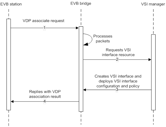
Figure 12 VDP pre-association and association establishment
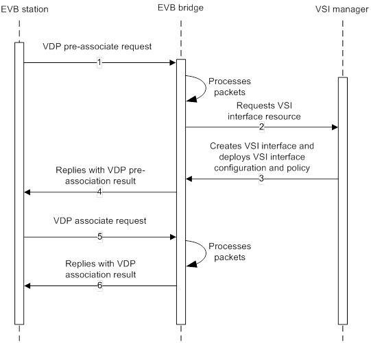
Figure 13 VDP de-association process
Message format
VDP uses ECP to carry VDP TLVs. A VDP TLV contains VSI manager ID TLV and VDP association TLV. A VSI manager ID TLV appears as the first TLV in an ECPDU. One or more of the VDP association TLVs can appear in an ECPDU following the VSI manager ID TLV.
Figure 14 VSI Manager ID TLV

Type—Takes the value of 0x05.
Manager ID—Represented as an IPv6 address. All 0s means the station does not know what VSI Manager ID to use, indicating that the bridge must select a default value.
Figure 15 VDP association TLV
![]()
Type—The value represents different VDP requests:
¡ 0x01—A VDP pre-association request.
¡ 0x02—A VDP pre-association request with resource reservation.
¡ 0x03—A VDP association request.
¡ 0x04—A VDP de-association request.
Reason—Comprises two parts: the first 4 bits is the error type code, and the last 4 bits represents the reason status. For more information about the reason status, see Table 3.
Field | Value | Description |
0Reason-Status Code (bit0 to bit3) | 0x00 | The VDP request is successfully completed by the bridge. |
0x01 | The VDP TLV format is invalid. | |
0x02 | The bridge does not have enough resources to complete the VDP operation successfully. | |
0x03 | The VSI manager is unreachable. | |
0x04 | The operation has failed for other reasons. | |
0x05 | The operation has failed because of an invalid VID, GroupID, or MAC address. | |
Others | Reserved. | |
M Flag (bit4) | 1 | The user of the VSI (the VM) is migrating. |
0 | The VM is not migrating. | |
S Flag (bit5) | 1 | The VM is suspended. |
0 | The VM is not suspended. | |
Req/Ack Flag (bit6) | 1 | The TLV contains a request by the station. |
0 | The TLV contains a response by the bridge. | |
Reserve (bit7) | NA | Reserved. |
VSI Type ID—Identifies a VSI type for which the VSI manager defines the corresponding policies, and can be applied to multiple VSIs.
VSI Type Version—Allows a VSI Manager Database to contain multiple versions of a given VSI Type.
VSI ID Format—For information about available VSI ID formats, see Table 4.
Field | Value | Description |
VSI ID format | 0x01 | An IPv4 address |
0x02 | An IPv6 address | |
0x03 | A MAC address | |
0x04 | The interpretation of the VSIID is locally defined. | |
0x05 | A UUID. | |
Others | Reserved. |
VSI ID—An identifier for the VSI instance. The VSIID remains constant during virtual station migration.
Filter Format—For information about available filter formats, see Table 5.
Field | Value | Description |
VSI filter format | 0x01 | VLAN (C-VLAN) |
0x02 | MAC + VLAN | |
0x03 | Group ID + VLAN | |
0x04 | Group ID + MAC+ VLAN | |
Others | Reserved. |
Filter Info—Contains information from which a filter can be constructed.
ECP
Edge Control Protocol (ECP) provides a transmit procedure with an acknowledgement mechanism for upper-layer application, and exchanges VDP TLVs between the EVB station and EVB bridge.
Exchange process
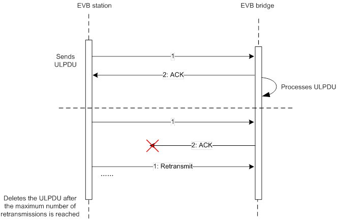
As shown in Figure 16, ECP works as follows:
1. ECP adds a sequence number to the TLV sent by VDP, encapsulates the TLV, and sends it to the bridge.
2. The bridge sends an ACK that contains the sequence number to the station.
If the station does not receive any ACKs after the timer expires, the station re-sends the message until the maximum number of retransmissions is reached.
If the bridge initiates the ECP exchange process, the process is the same.
Message format
Figure 17 ECP data unit structure
![]()
Eth Type—Contains the Ethernet type (0x8940).
Version—Identifies the protocol version, and takes a value of 0x01.
Operation Type—A value of 0x00 indicates an ECP request, and 0x01 indicates an ECP acknowledgement.
Subtype—A value of 0x0001 represents VDP, and is ignored for an acknowledgement.
Sequence Number—The starting sequence number can start anywhere for the first ECPDU, but the sequence number for each subsequent new request ECPDU is incremented by 1.
Operating mechanism
Network architecture
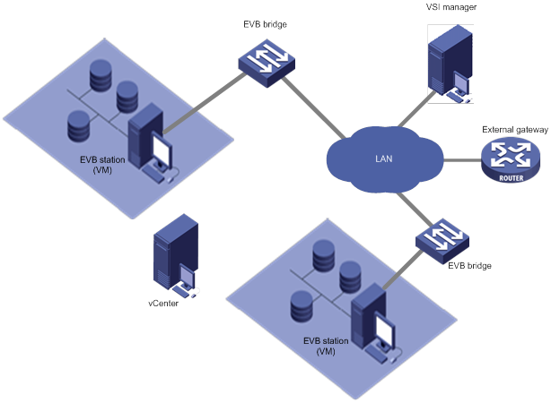
As shown in Figure 18, the data center network that supports EVB contains EVB stations (VMs), EVB bridges, the vCenter, and IMC (VSI manager).
Figure 18 Network architecture
EVB station
An EVB station contains one or more ERs, and transmits CDCP TLVs and EVB-TLVs through LLDP to negotiate the S-channel creation and EVB capabilities. It must support VDP and ECP to instruct the bridge to create, migrate, or delete a VM.
For more information about EVB stations, see IEEE P802.1Qbg.
EVB bridge
An EVB bridge negotiates EVB capabilities, such as ECP retransmission times, with a station.
If S-channels are required, the bridge needs to:
Create, maintain, and delete the S-channel.
Implement the RR service for the S-channel.
Add or remove an S-tag for a message that is received or sent by the station.
The bridge exchanges the current VM status with the station through ECP/VDP, notifies the VSI manager, and sends the result as a reply to the station.
After VMs are successfully created, the VSI manager notifies the bridge to create a VSI interface, and apply traffic management policies according to VSI filters on the VSI. When the station shuts down a VM, the bridge deletes all corresponding policies, and shuts down the VSI interface.
VSI manager
A VSI manager stores a database that holds traffic policies and management policies for VSIs, and deploys these policies when a VM connects to the switching network. This implements unified VSI policy management.
You can create a VSI management database on an NMS. The database contains information about the VSI type, VSI type version, and the corresponding network policies for the VSI type. For information about the network policies, see Table 6.
Table 6 Network policy contents
QoS | Traffic classification based on quintuple, Ethernet header information, and Layer-4 information. |
Priority tag based on VM traffic classification. | |
Line rate based on VM traffic classification. | |
ACL | VM-based access control and traffic filtering. Hardware line rate filtering is supported. |
Mirroring | Traffic mirroring based on VMs and traffic classification. Sampling is supported. |
Statistics | VM-based traffic classification statistics. |
vCenter
You can query the VSI management database on an NMS and configure and create VMs and its VSI instance, assign a VSIID for the VSI instance, specify VSI type ID, and configure VSI filters on the vCenter according to the information retrieved from the database.
During a VM migration, the vCenter notifies the original VM to send a de-associate request and the new VM to change its status from pre-associate to associate, and instructs the VM to notify the network devices in the data center to refresh the MAC addresses of frames during the migration.
VM creation
Figure 19 Creating a VM and automatically deploying network policies
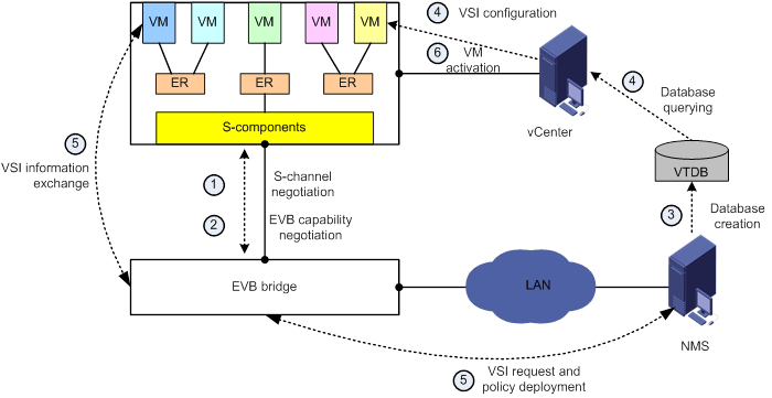
As shown in Figure 19, a VM association involves six phases: S-channel negotiation, EVB capability negotiation, VTDB creation, VSI instance creation, VSI creation and policy application, and VM activation.
S-channel negotiation
After EVB is enabled on an Ethernet port, the station exchanges CDCP TLVs with the bridge to negotiate whether S-channel is supported, and what S-channels are required:
If neither the station nor the bridge supports S-channels, no S-tag is added to or removed from the frames sent between VMs and the bridge, and EVB TLVs, ECP, and VDP operate on the Ethernet port.
If the station does not support S-channels, the bridge considers all traffic from a default S-channel, and EVB TLVs, ECP, and VDP operate on the default S-channel interface. No S-tag is added to or removed from the frames sent between VMs and the bridge.
If both the station and bridge support S-channels, CDCP TLVs sent by the station contain the ID of the S-channel to be created. The bridge assigns an SVID for the S-channel, and creates a corresponding S-channel interface.
EVB capability negotiation
If an S-channel (including the default S-channel) is created, the station and bridge negotiate EVB capabilities through the S-channel. If no S-channel is created, the negotiation is performed through an Ethernet port.
Parameters that are negotiated include whether the station requests the RR service for the S-channel, the bridge decides whether to enable RR, the maximum value of ECP retransmission times, RTE, VDP RWD, and VDP RKA.
After the negotiation, the bridge determines whether to configure RR for the S-channel based on the negotiation results.
VTDB creation
You can create a VSI Type database (VTDB) on an NMS, where you specify the version of a VSI type and VSI type ID.
Each VSI type has its corresponding network traffic policies such as QoS and security policies.
VSI instance creation
To create a VSI instance, query the VTDB for the VSI type and corresponding traffic policies and select a VSI type ID for the newly-created VM. A VSI instance is an object of a VSI type, and a VSIID is a globally unique number in 16 bytes.
Then, you configure the VTID, VSI type version, and VSI ID on the VM, associate the VSI filter with the VSI, and enable VDP on the station.
VSI creation and policy application
1. A VM sends a VDP request that contains VSI type ID, VSI type version, VSI ID, VSI ID format, and VSI filters to the bridge after being created.
2. After verifying the validity of the message, the bridge adds a local ID of the VSI interface in the request and sends it to the VSI manager.
3. The VSI manager queries the VTDB according to the VSI type ID and VSI type version in the request, notifies the corresponding bridge (identified by local ID) to create the VSI interface, and associates the VSI filter with the VSI interface. After the VSI interface is created, the VSI manager applies the policy for the VSI type to the VSI interface on the bridge to validate the VSI interface.
4. The VSI manager notifies the bridge that the VSI interface is successfully created, and the bridge sends a reply to the VM.
If the policy configuration fails, the VSI manager notifies the bridge, which sends an association failure reply to the VM.
5. The VM periodically sends VDP association requests as keepalive messages to the bridge.
VM activation
After the association request is successfully processed, the vCenter activates the VM to process traffic.
VM migration
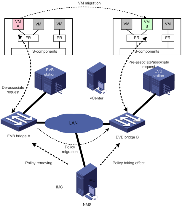
Figure 20 shows a VM migration process. A VM migration process might involve service data and status copying between the original and new VMs. This document does not describe the data copying process among VMs.
Creating a VSI instance on the new VM
On the vCenter, create a VSI instance on VM B by using the same VSI type ID, VSI type version, and VSI ID as VM A, associate the VSI instance with VSI filters, and enable VDP for the station where VM B resides.
VSI pre-association and policy application for the new VM
1. VM B sends a VDP pre-associate request to EVB bridge B that directly connects to VM B. The request contains the VSI type ID, VSI type version, VSI ID, VSI ID format, and VSI filters.
2. After verifying the validity of the request, EVB bridge B adds a local ID of the VSI in the request and sends the request to the VSI manager.
Because VM migrations can be accomplished on different bridges, the local IDs of VM A and VM B can be the same or different.
3. The VSI manager searches the VTDB for the VSI type ID and VSI type version, notifies EVB bridge B to create a VSI interface, and associates the VSI filter with the VSI interface. Then the VSI manager notifies EVB bridge B that the VSI interface is in pre-association mode.
After the VSI interface is created, the VSI manager applies the policy for the VSI type in the VTDB to the VSI on EVB bridge B, but the policy does not take effect immediately.
4. The VSI manager notifies EVB bridge B that the VSI has been successfully pre-associated.
5. EVB bridge B sends a reply to VM B.
Shutting down the original VM
1. The vCenter notifies VM A to delete the association with EVB bridge A, and VM A sends a de-associate request to EVB bridge A.
2. EVB bridge A deletes the VSI interface, clears the policy configuration on the VSI interface, notifies the VSI manager of shutting down VM A, and sends a reply to VM A. The de-association is successfully processed.
Creating a new VM
1. The vCenter notifies VM A to delete the association with EVB bridge A, and notifies VM B to prepare for the association with EVB bridge B. VM B sends an associate request to EVB bridge B.
2. EVB bridge B transits the VSI interface to the association state, and the corresponding policies take effect. Meanwhile EVB bridge B notifies VM B that the association request is successfully processed.
3. The vCenter instructs VM A to send MAC address refresh frames during the de-association process. After the de-association request is successfully processed, the vCenter activates VM B to transmit traffic.
4. VM B periodically sends VDP association requests as keepalive messages to EVB bridge B.
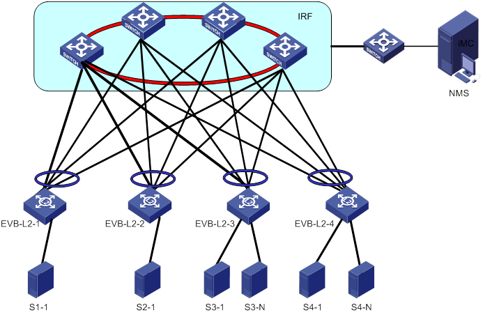
Application scenarios
An EVB implementation enables VMs to access the Layer 2 network of a data center, and can manage VM traffic and apply relevant policies to the VMs. As shown in Figure 21, EVB ensures automatic network policy re-deployment during a VM migration. This greatly reduces network management costs.
References
IEEE P802.1Qbg, Virtual Bridged Local Area Networks—Amendment: Edge Virtual Bridging.