Country / Region
- Products and Solutions
- Industry Solutions
- Services
- Support
- Training & Certification
- Partners
- About Us
- Contact Sales
- Become a Partner
-
 Login
Login
Country / Region
TRILL Technology White Paper
Copyright © 2018 New H3C Technologies Co., Ltd. All rights reserved. No part of this manual may be reproduced or transmitted in any form or by any means without prior written consent of New H3C Technologies Co., Ltd. The information in this document is subject to change without notice. |
|
Contents
Challenges facing Layer 2 networks
TRILL implementation on H3C devices
Overview
Background
The fast expansion of data centers brings problems such as low utilization of hardware resources, and growth of power consumption and management costs. Server virtualization aims at solving these problems.
Server virtualization enables a physical server to run multiple applications that were run on multiple physical servers.
With server virtualization, servers might be relocated, which requires the support of a flexible Layer 2 network. In addition, the Layer 2 network must be highly scalable to provide enough bandwidth for the increasing number of servers.
The tradition Layer 2 network structure is designed to provide high availability for static applications. It cannot satisfy those needs brought by server virtualization.
Challenges facing Layer 2 networks
Traditional Layer 2 networks use STP to eliminate loops. STP is not suitable for data center networks because of the following limitations:
Waste of bandwidth—Redundant links are blocked to avoid loops.
Restricted scope—The STP network is divided through Layer 3 networks to avoid broadcast storms, so the Layer 2 network size is restricted.
Excessive MAC learning—Switches on STP links must learn the MAC addresses of all terminals.
All these limitations restrict the size of STP networks.
Figure 1 Traditional STP network
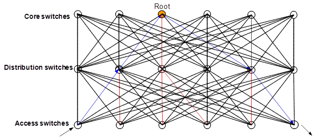
Layer 2 switching has good flexibility but has above-mentioned limitations. Layer 3 routing has good stability, scalability, and performance but requires complicated configurations and lacks flexibility. New technologies such as virtualization cannot be easily deployed on traditional data center networks and most of their configurations are not replicable. All these things impact the development of data centers.
Transparent Interconnection of Lots of Links (TRILL) integrates the advantages of Layer 3 routing into Layer 2 networks. TRILL is suitable for building large flat Layer 2 networks for data centers, featuring good flexibility, high expandability, high scalability, and high performance.
Benefits
TRILL provides the following benefits.
Simplified configuration and reduced management costs—TRILL simplifies configuration and reduces management costs in the following aspects:
H3C RBs need few configurations, which include enabling TRILL and configuring link types for ports (a trunk port connects to a distribution switch, and an access port connects to terminals). Other parameters do not need configuration. Nicknames of RBs are automatically assigned.
TRILL uses a single control protocol to complete unicast forwarding, multicast forwarding, and VLAN pruning, which reduces management and configuration workloads.
When servers are moved or changed, TRILL can dynamically adapt to the changes, while IP networks must be reconfigured.
Mature IS-IS—TRILL uses the mature link state protocol IS-IS to implement fast routing convergence and support large Layer 2 networks. TRILL uses a TTL field to mitigate loop issues and uses RPF to remove loops.
High efficiency and high performance—TRILL provides high efficiency and high performance in the following aspects:
TRILL can fully utilize links between RBs through ECMP.
TRILL forwards frames to their destinations through a shortest path tree to improve forwarding efficiency.
Distribution layer devices do not need to learn the MAC addresses of terminals.
TRILL fundamentals
Terminology
RBridge—Routing bridge (RB) that runs TRILL. RBs are classified into ingress RBs, transit RBs, and egress RBs, depending on their positions in the TRILL network. A frame enters the TRILL network through an ingress RB, travels along transit RBs, and leaves the TRILL network through an egress RB.
TRILL network—A Layer 2 network that contains RBs.
System ID—Unique identifier of an RB in the TRILL network. The system ID is 6 bytes in length.
Nickname—Address of an RB in the TRILL network. The nickname is 2 bytes in length.
Designated Routing Bridge (DRB)—Similar to the designated IS (DIS) in IS-IS, a DRB exists in a broadcast network. It helps simplify network topology, and assigns AVFs and appointed ports for the VLANs on each RB in the broadcast network.
Appointed VLAN-x Forwarder (AVF) and appointed port—To avoid loops, TRILL requires all traffic of a VLAN on a broadcast network to enter and leave the TRILL network through the same port of an RB. The RB is the VLAN's AVF, and the port is the VLAN's appointed port.
Link State Protocol Data Unit (LSPDU) —An LSP describes local link state information and is advertised between neighbor devices.
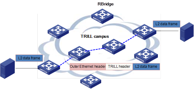
TRILL overview
In a TRILL campus as shown in Figure 2, each RB uses a link state protocol to learn topology information, and uses SPF to compute shortest unicast routes to other RBs and multicast routes. When an ingress RB receives an Ethernet frame, it looks up the MAC address table. If a match is found, the RB encapsulates the Ethernet frame into a TRILL frame, and forwards it through a TRILL unicast route. If no match is found, the RB encapsulates the frame (unknown unicast, multicast, or broadcast) into a TRILL frame and forwards it through a TRILL multicast route. When the egress RB receives the TRILL frame, it de-encapsulates it and forwards the original Ethernet frame.
TRILL adds a TTL field into the TRILL header to mitigate loop issues. When the TTL expires, the frame is discarded.
TRILL control protocol
TRILL uses extended IS-IS to advertise reachability information and uses SPF to compute routes based on the IS-IS LSDB.
Nickname assignment
TRILL uses a two-byte nickname to uniquely identify a RB. The nickname is a simplified IS-IS ID of the RB. A TRILL frame carries the nicknames of the ingress and egress RBs in the frame header.
RBs advertise their nicknames in LSPs. If an RB receives an LSP that has the same nickname as its own, the RB compares its nickname priority and system ID with those of the advertising RB. The RB with a higher priority uses the nickname. If they have the same priority, the RB with a higher system ID uses the nickname. The loser must re-select a nickname.
DRB election
On a broadcast network, TRILL elects a DRB to create pseudonodes and generate LSPs for them. To avoid loops, the DRB also appoints an AVF for each VLAN.
Upon startup, each RB considers itself as the DRB until it receives a TRILL hello from a higher-priority RB. If an RB does not receive any TRILL hellos from the DRB for a certain time, it re-considers itself as the DRB. To ensure stable neighbor relationships, DRB election is started after two hello intervals since startup.
DRB election considers only priority and MAC without considering whether the link is bidirectional (a link is unidirectional if the neighbor list in a TRILL hello received does not contain the receiving RB). This mechanism ensures that only one DRB exists on a broadcast network to avoid loops. However, an LSP carries only neighbors that have bidirectional links to the advertising RB.
AVF selection and suppression
To avoid loops, a broadcast network only has one AVF to forward traffic for a VLAN. The AVF is appointed by the DRB. The DRB advertises AVF information in TRILL hellos. During network oscillation, a VLAN might have multiple AVFs. AVF suppression is used to avoid this problem.
When the root bridge is changed (triggered by STP BPDU), an RB that is the AVF of some VLANs suppresses the AVF for 30 seconds (default). During the suppression interval, the RB does not forward traffic for those VLANs. If the RB receives a hello that has new AVF information from the DRB within the suppression interval, the RB updates AVF information for those VLANs and stops AVF suppression. If the RB does not receive new AVF information until the suppression timer expires, it stops AVF suppression and forwards traffic for those VLANs as their AVF.
If RB 1, the AVF of VLAN X, receives a hello from another RB that declares itself as the AVF of VLAN X (the hello is originated from VLAN X), RB 1 stops acting as the AVF of VLAN X by moving VLAN X from the forwarded-VLAN list to the suppressed-VLAN list and starts a suppression timer. The suppression interval is five times the hello interval (the suppression interval must be longer than the hello interval on the DRB). If a hello that carries new AVF information for VLAN X is received from the DRB within the suppression interval, the RB removes VLAN X and the suppression timer. If no new AVF information is received for VLAN X before the suppression timer expires, the RB stops suppression and acts as the AVF of VLAN X.
Multi-port AVF identification
If a DRB sends a hello that appoints an RB as the AVF of a VLAN and the appointed RB has multiple ports on the broadcast network, all those ports of the RB can receive the hello. In this case, the RB selects one of those ports as the AVF of that VLAN to avoid loops. The RB uses the pseudo ID in hello frames to determine whether they are from the same source, and considers the ports that receive the same hello as a port group.
TRILL route generation
TRILL generates both unicast and multicast routes. Unicast routes direct forwarding of known unicast traffic, and multicast routes direct forwarding of unknown unicast, broadcast, and multicast traffic.
Unicast route generation
RBs advertise nickname information in LSPs. Each RB uses SPF to generate a shortest path tree with itself as the root, and then generates unicast routes according to the shortest path tree and nicknames of other RBs. TRILL unicast routes support ECMP to implement load sharing for traffic destined for the same egress RB.
Multicast route generation
RBs advertise their nickname, root priority, multicast calculation capability, AVF, multicast routers, and multicast receivers in LSPs. Each RB prioritizes received nicknames by root priority and generates a specified number of multicast trees. The number is specified by the RB with the highest root priority and cannot exceed the lowest multicast calculation capability.
Then each RB uses SPF to generate a shortest path tree with the specified root and generates multicast routes according to the shortest path tree, AVF, multicast routers, and multicast receivers. A multicast route contains an ID and a list of egress ports. The ID indicates whether the local network of the RB has multicast receivers. If yes, the RB de-encapsulates received TRILL data frames. The port list contains one or multiple egress ports. Each port connects to a downstream RB that has multicast receivers on its network.
TRILL data forwarding
Upon receiving an Ethernet frame, TRILL adds a TRILL header and an outer Ethernet header and forwards the TRILL frame through the TRILL routing table. The egress RB de-encapsulates the TRILL frame and forwards the original Ethernet frame. TRILL frames are classified into known unicast frames and multicast frames (unknown unicast, broadcast, and multicast frames).
The ingress RB forwards an unknown unicast frame through the multicast route table. Upon receiving the frame, the egress RB uses the source MAC address of the frame and the ingress nickname to create a MAC address entry for the ingress RB. After a request-reply process, the ingress RB and egress RB both learn a MAC-RB binding and forward subsequent frames through the unicast route. The ingress RB adds the nickname of the RB that matches the destination MAC address into the Egress RB field, adds its own nickname into the Ingress RB field, sets the M bit to 0, and forwards the frame.
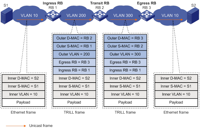
Upon receiving a known unicast frame, a transit RB checks whether it is the egress RB in the frame. If yes, it de-encapsulates the frame. If not, it uses the egress RB to look up the TRILL unicast route table and the next hop table, updates the outer Ethernet header (changes the destination MAC address to the MAC address of the next hop and changes the source MAC address to its own MAC address), and sends the frame through the specified port. During forwarding, the TRILL header only has the Hop Count field changed. Figure 4 shows how a frame is forwarded through a TRILL network.
Figure 3 TRILL frame format in Ethernets
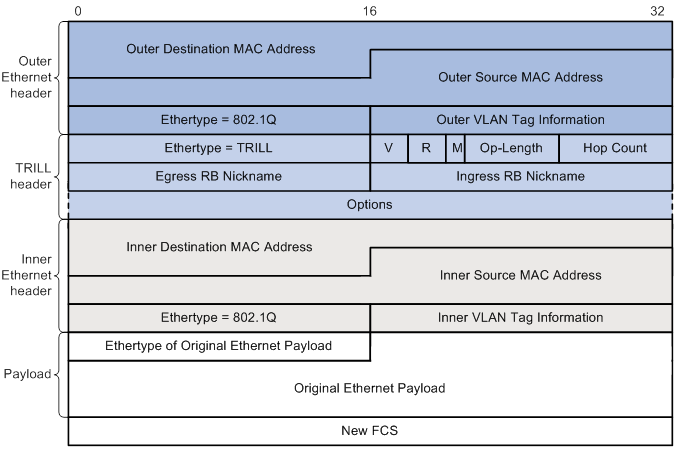
Figure 4 Forwarding of a known unicast frame
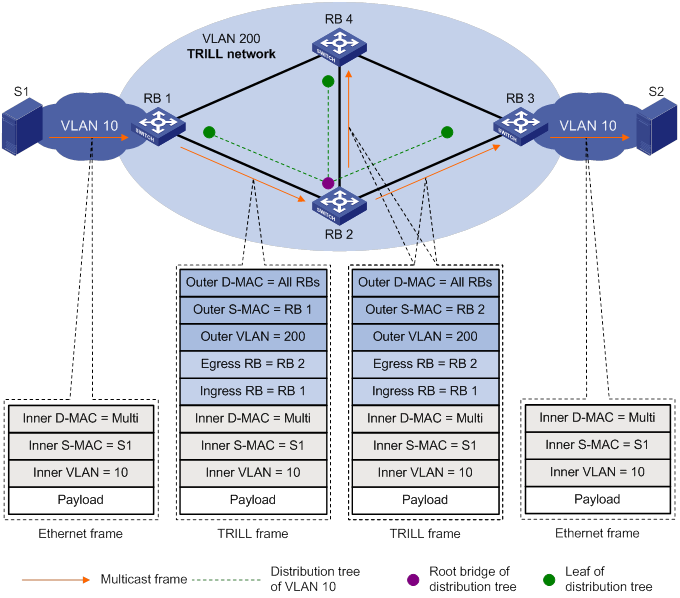
Upon receiving a multicast frame (an unknown unicast, a broadcast, or a multicast frame), the ingress RB selects a multicast tree root according to the configured rules such as VLAN-based load sharing. Then the ingress RB adds the nickname of the root to the Egress RB field of the TRILL header, adds its own nickname to the Ingress RB field, and sets the M bit to 1. In the outer Ethernet header, the destination MAC address is fixed to the All-RBridges address 01-80-C2-00-00-40, and the source MAC address is changed on each transit RB.
The matching multicast entry is found by using RB+VLAN+MAC, RB+VLAN, and RB as the key in turn. The frame is forwarded through the ports specified in the multicast entry. If the matching multicast entry has an Egress flag, the RB also de-encapsulates the frame and forwards it to the local network. Figure 5 shows how a multicast frame is forwarded through the TRILL network.
Figure 5 Forwarding of a multicast frame
Different from IP routing that needs complicated configurations, TRILL automatically assigns addresses (nicknames) to RBs and uses the nicknames to generate a routing table that directs the forwarding of unicast and multicast packets. TRILL integrates the advantages of routing into Layer 2 networks. A TRILL network has both the simplicity and flexibility of Layer 2 networks and the stability and scalability of Layer 3 networks.
TRILL implementation on H3C devices
H3C TRILL-capable switches are the basis of new-generation data centers featuring good scalability, high performance, and good manageability. Together with H3C proprietary IRF technology, TRILL can simplify and expand the infrastructures of data centers. TRILL supports ECMP routes and provides optimal bandwidth between any two RBs. The size of a TRILL network is not restricted. Theoretically, a TRILL network can be infinitely expanded.
Typical TRILL applications
Large Layer 2 data center networks
Generally, a large data center is divided into multiple subnets because of the limitations of STP. As shown in Figure 6, Data Center A has two subnets that communicate with the core devices through Layer 3 routing. To add uplink bandwidth for the subnets, you can create virtual switches by using H3C IRF technology. IRF can avoid loops without needing STP and implement load sharing, but IRF is not suitable when many switches needed to be virtualized. Therefore, the uplink bandwidth becomes the bottleneck. In addition, the subnets are restricted in size because of STP, and servers cannot be easily moved because of complex configurations.
Figure 6 Conventional data center network
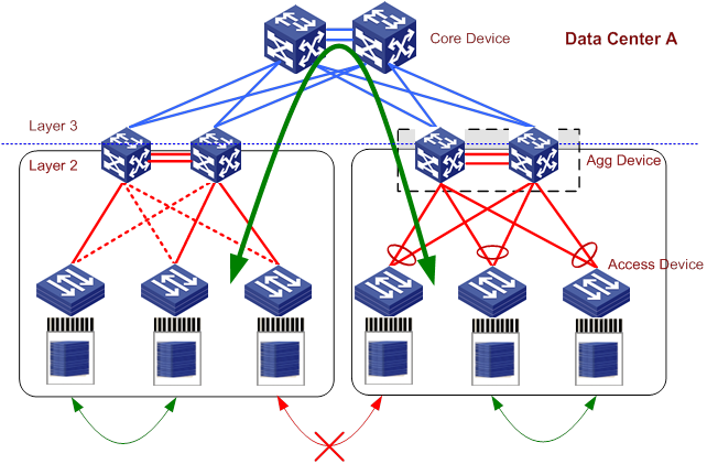
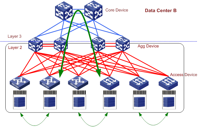
Figure 7 shows a TRILL-based data center network. Although Data Center B has different cabling from Data Center A, they have the same numbers of links and switches. In Data Center B, each access switch connects to multiple distribution switches. TRILL runs between access switches and distribution switches. TRILL removes routing loops, supports ECMP, and has better bandwidth expansion capability. With TRILL, servers can be easily moved. TRILL implements a large Layer 2 network without subnetting.
Figure 7 TRILL-based data center network
TRILL brings the following benefits:
Simplified configuration
In Data Center A, switches have different IRF, STP, IP address, and IP routing configurations.
In Data Center B, TRILL removes the need of complex configurations on switches.
Dynamic moves
In Data Center A, access switches in different areas communicate with each other through Layer 3 routing. Therefore, it is difficult to move servers between areas because of complex configurations.
In Data Center B, all access switches are reachable to each other at Layer 2. Therefore, servers can be easily moved.
High bandwidth
In Data Center A, each access switch uses a 40G link to connect to a peer switch in the same area. All access switches in the same area share limited uplink bandwidth to connect to switches in other areas.
In Data Center B, each access switch can fully utilize its own 40 G link without uplink bandwidth limitation and implement shortest paths and ECMP.
High availability
In Data Center A, the failure of a distribution switch reduces 50% bandwidth of access switches.
In Data Center B, the failure of a distribution switch reduces 25% bandwidth of access switches.
High performance computation
Data center networks are designed to minimize communication overhead for servers. In conventional data centers, Layer 3 boundaries are often deployed close to the STP root bridge to process south-north traffic. To remove loops, any two switches can use only one link to send traffic even if there are multiple links between them. Because east-west traffic is often excessive, the bandwidth restriction seriously affects bidirectional traffic forwarding.
TRILL introduces ECMP of Layer 3 routing to remove the restriction of STP.
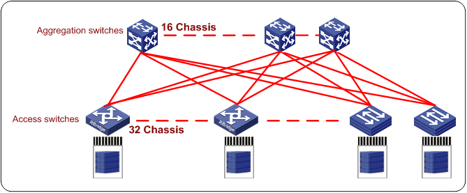
In the TRILL network as shown in Figure 8, each access switch is connected to 16 distribution switches and provides a bandwidth 16 times the bandwidth of an STP network. Each access switch can reach any devices over the 16 links. Integrated with H3C IRF and 40G/100G technologies, the TRILL network provides higher computation capabilities.
Figure 8 TRILL network with high performance computation
Summary
TRILL combines the advantages of Layer 2 switching and Layer 3 routing to provide a simply, scalable, and high-performance data center solution. It removes the limitations of conventional STP-based Layer 2 networks.
Protocols and standards
RFC 6325, Routing Bridges (RBridges): Base Protocol Specification
RFC 6326, Transparent Interconnection of Lots of Links (TRILL) Use of IS-IS
RFC 6327, Routing Bridges (RBridges): Adjacency
RFC 1195, Use of OSI IS-IS for Routing in TCP/IP and Dual Environments