- Table of Contents
-
- 07-Layer 3—IP Services Configuration Guide
- 00-Preface
- 01-ARP configuration
- 02-IP addressing configuration
- 03-DHCP configuration
- 04-DNS configuration
- 05-HTTP configuration
- 06-IP forwarding basics configuration
- 07-Fast forwarding configuration
- 08-Adjacency table configuration
- 09-IRDP configuration
- 10-IP performance optimization configuration
- 11-UDP helper configuration
- 12-IPv6 basics configuration
- 13-IPv6 neighbor discovery configuration
- 14-DHCPv6 configuration
- 15-IPv6 fast forwarding configuration
- 16-WAAS configuration
- 17-HTTP redirect configuration
- 18-Web caching configuration
- Related Documents
-
| Title | Size | Download |
|---|---|---|
| 16-WAAS configuration | 286.18 KB |
Contents
Packet duplication operating mechanism
Restrictions and guidelines: WAAS configuration
Applying a WAAS policy to an interface
Configuring WAAS to operate in asymmetric mode
Configuring DRE optimization parameters
Configuring FEC optimization parameters
Configuring packet duplication optimization parameters
Enabling packet duplication RIR
Manually specifying a packet duplication path in an SDWAN network
Setting the packet duplication reorder timeout timer
Configuring the TFO blacklist autodiscovery feature
Restoring or creating the predefined WAAS policy
Verifying and maintaining WAAS
Verifying WAAS configuration and running status
Example: Applying the predefined WAAS policy
Example: Configuring a user-defined WAAS policy
Configuring WAAS
About WAAS
The Wide Area Application Services (WAAS) feature is a set of services that can optimize WAN traffic. WAAS solves WAN issues such as high delay and low bandwidth by using optimization services. WAAS provides the following TCP optimization services:
· Forward Error Correction (FEC).
· Transport Flow Optimization (TFO).
· Data Redundancy Elimination (DRE).
· Lempel-Ziv compression (LZ compression).
· Packet duplication.
TFO
TFO optimizes TCP traffic without modifying packet header information. TFO uses the following optimization methods:
· Slow start optimization.
· Increased buffering.
· Congestion algorithm optimization.
· Selective acknowledgement.
Slow start optimization
The initial congestion window size for TCP slow start is one TCP segment. During slow start, TCP doubles the congestion window size for each received ACK that acknowledges new data. In this manner, the congestion window will reach an appropriate value by examining the congestion status. In a WAN environment, the congestion window takes a long time to reach an appropriate size because of high delay.
Slow start optimization shortens the slow start process by increasing the initial congestion window size.
Increased buffering
TCP has a maximum buffer size of 64 KB. After the sender sends 64 KB data, it must wait for an ACK from the receiver before continuing to send data. This mechanism wastes bandwidth on a WAN link.
Increased buffering increases the TCP buffer size to a maximum of 16384 KB. This improves link efficiency.
Congestion algorithm optimization
TCP uses the congestion window to control congestion. The window size indicates the size of data that can be sent out before an ACK is received. The window size changes with the congestion status. The greater the window size, the faster the data rate. A higher data rate more likely causes congestion. The smaller the window size, the lower the data rate. A lower data rate causes low link efficiency.
Congestion algorithm optimization achieves a trade-off between the data rate and congestion by selecting the optimum window size.
Selective acknowledgement
TCP uses a cumulative acknowledgement scheme. This scheme forces the sender to either wait a roundtrip time to know each lost packet, or to unnecessarily retransmit segments that have been correctly received. When multiple nonconsecutive segments are lost, this scheme reduces overall TCP throughput.
Selective acknowledgement (SACK) allows the receiver to inform the sender of all segments that have arrived successfully. The sender retransmits only the segments that have been lost.
DRE
DRE reduces the size of transmitted data by replacing repeated data blocks with shorter indexes. A WAAS device synchronizes its data dictionary to its peer devices. A data dictionary stores mappings between repeated data blocks and indexes.
Replacing repeated data blocks with indexes is called DRE compression. Replacing indexes with repeated data blocks is called DRE decompression.
DRE compression process
DRE compresses data in the following process:
1. The sending WAAS device caches TCP data and sends a large data block to the DRE module.
2. The DRE module divides the large data block into non-overlapping data blocks.
¡ For a repeated data block, the DRE module performs the following operations:
- Replaces the data block with its index and creates an MD5 digest for the data block.
- Sends the index and MD5 digest to the peer.
¡ For a non-repeated data block, the DRE module performs the following operations:
- Creates an index for the data block and adds it to the local data dictionary.
- Creates an MD5 digest for the data block and sends the data block, index, and MD5 digest to the peer.
To improve calculation speed and efficiency, DRE uses a sliding window mechanism to segment data and detect data redundancy. This mechanism detects repeated data blocks by using a fixed-size window to compare the original data byte by byte with data blocks in the dictionary.
DRE decompression process
DRE decompresses data in the following process:
1. The receiving WAAS device reconstructs the original data.
¡ For an index, the device replaces the index with its data block after querying the data dictionary.
If the query fails, the decompression fails, and the receiving WAAS device waits for the peer to retransmit the data.
¡ For an index and a data block, the device creates an entry for them and adds the entry to the local data dictionary.
2. The receiving WAAS device calculates an MD5 digest for the original data and compares the calculated MD5 digest with the MD5 digest in the packet.
¡ If the two MD5 digests are the same, the decompression succeeds.
¡ If the two MD5 digests are different, the decompression fails, and the receiving WAAS device waits for the peer to retransmit the data.
LZ compression
LZ compression is a lossless compression algorithm that uses a compression dictionary to replace repeated data in the same message. The compression dictionary is carried in the compression result. The sending device uses the sliding window technology to detect repeated data.
Compared with DRE, LZ compression has a lower compression ratio. LZ compression does not require synchronization of compression dictionaries between the local and peer devices. This reduces memory consumption.
FEC
About FEC
Forward error correction (FEC) is a mechanism to control errors during data transmission by adding data redundancy to the transmitted packets. Specifically, the FEC sender encodes original packets and generates redundant packets. The header information of a redundant packet includes the number of original packets, the number of redundant packets, and sequence numbers. The FEC receiver decodes received data and recovers lost packets according to the received original packets and redundant packets.
Basic concepts
· FEC average ratio—Controls the number of redundant packets generated. The greater the FEC average ratio, the more the redundant packets generated. FEC average ratio must be greater than the actual packet loss ratio.
· Encoding timeout time—Affects the number of original packets that can be encoded at a time. If the encoding timeout time expires before the maximum number is reached, the number of actually encoded packets are sent.
· Block size—Specifies the maximum number of original packets that can be encoded at a time. If the block size is too small, the number of generated redundant packets is small. If the block size is too large, the decoder side will take a long time to recover lost packets.
Both the encoding timeout time and the block size affect the number of original packets that can be encoded at a time. If the maximum number of encoded packets is reached before the encoding timeout time expires, that number applies. If the encoding timeout time expires before the maximum number is reached, the number of actually encoded packets applies.
· Decoding timeout time—Affects the number of original packets that can be decoded at a time. If the total number of cached original packets and redundant packets is smaller than the block size when the decoding timeout time expires, the decoder sends cached original packets and drops cached redundant packets without decoding any packets.
· Sampling interval—The decoder regularly sends sampled packets to notify the encoder of the real-time packet loss ratio. The encoder adjusts the FEC average ratio based on the real-time packet loss ratio. This parameter is supported only for A-FEC.
· Aging time for A-FEC decoder information—If the encoder does not receive sampled packets within the aging time, it deletes the local decoder information and uses the set FEC average ratio.
FEC types
FEC types include adaptive FEC (A-FEC) and determined FEC (D-FEC).
· A-FEC adjusts the FEC average ratio based on the calculated real-time packet loss ratio. The encoder adds device address information to redundant packets. The decoder regularly sends sampled packet loss ratio to the encoder. The encoder will adjust the number of generated redundant packets to reduce the amount of data transmitted on the WAN link.
· D-FEC always uses the set FEC average ratio.
How FEC works
FEC processes packets as follows:
1. The encoder identifies audio or video sessions.
a. When the device receives an audio or video request packet, it marks an ALG flag for the packet, and generates a session and a relation table. For more information about sessions, see session management in Security Configuration Guide.
b. When the device receives a data packet, it matches the packet against WAAS policies. If a match is found, the device creates a fast forwarding entry and sets the fast forwarding flag.
2. The encoder encodes packets.
a. Caches original packets.
b. When the number of cached packets reaches the block size or the encoding timeout time expires, the device encodes the cached packets to generate redundant packets, and sends all of them.
3. The encoder decodes packets.
a. Caches received original packets and redundant packets.
b. When the total number of cached original packets and redundant packets reaches or exceeds the set number of original packets before the decoding timeout time expires, the decoder performs the following operations:
i Decodes the cached packets.
ii Recovers lost packets.
iii Sends original packets and recovered packets, and drops redundant packets.
Otherwise, the decoder sends cached original packets and drops cached redundant packets without decoding any packets.
Packet duplication operating mechanism
When real-time audio/video interaction is performed on the Internet, the links might encounter bandwidth limit, delay, jitter, and error code issues. At the same time, the error correction and retransmission on the transport layer and application layer exacerbate the bandwidth and delay issues, which decreases the audio/video data transmission quality. As a result, the audio/video often gets stuck and then plays fast.
Currently, most LANs access a WAN through multiple WAN links. The packet duplication feature takes the advantage of multiple WAN links to send one packet over two links, which effectively reduces or even avoids the audio/video lag issues caused by packet loss on a single link. The detailed workflow is as follows:
1. A WAAS policy with the optimization action as packet duplication is applied to a WAN interface.
2. When a WAN interface receives a packet that matches the criteria, the system looks up for ECMP routes, and duplicates the packet to the link of the first ECMP route. The device forwards the packet on the links of the WAN interface and the outgoing interface of the matching ECMP route at the same time.
3. The receiver integrates the packets received on the two links and drops the duplicate packet according to the packet characteristics.
Protocols and standards
· RFC 1323, TCP Extensions for High Performance
· RFC 3390, Increasing TCP's Initial Window
· RFC 2581, TCP Congestion Control
· RFC 2018, TCP Selective Acknowledgment Options
· RFC 3042, Enhancing TCP's Loss Recovery Using Limited Transmit
· RFC 2582, The NewReno Modification to TCP's Fast Recovery Algorithm
Restrictions and guidelines: WAAS configuration
For the WAAS feature to work correctly, make sure fast forwarding load sharing is disabled. For information about fast forwarding load sharing, see Layer 3—IP Services Configuration Guide.
WAAS tasks at a glance
To configure WAAS, perform the following tasks:
1. Configuring a TCP WAAS class
2. Configuring a UDP WAAS class
4. Applying a WAAS policy to an interface
5. (Optional.) Configuring WAAS to operate in asymmetric mode
6. (Optional.) Configuring TFO parameters
7. (Optional.) Configuring the TFO blacklist autodiscovery feature
8. (Optional.) Configuring DRE optimization parameters
9. (Optional.) Configuring FEC optimization parameters
10. (Optional.) Configuring packet duplication optimization parameters
11. (Optional.) Restoring or creating the predefined WAAS policy
12. (Optional.) Deleting all WAAS settings
Configuring a TCP WAAS class
1. Enter system view.
system-view
2. Create a WAAS class and enter WAAS class view.
waas class class-name
By default, no WAAS classes exist.
3. Configure a TCP match criterion.
match [ match-id ] tcp any [ ip-address { ip-address [ mask-length | mask ] | object-group ip-object-group-name } | ipv6-address { ipv6-address [ prefix-length ] | object-group ipv6-object-group-name } ] [ port { port-list | object-group port-object-group-name } ]
match [ match-id ] tcp { destination ip-address { ip-address [ mask-length | mask ] | object-group ip-object-group-name } [ port { port-list | object-group port-object-group-name } ] | source ip-address { ip-address [ mask-length | mask ] | object-group ip-object-group-name } [ port { port-list | object-group port-object-group-name } ] } *
match [ match-id ] tcp { destination ipv6-address { ipv6-address [ prefix-length ] | object-group ipv6-object-group-name } [ port { port-list | object-group port-object-group-name } ] | source ipv6-address { ipv6-address [ prefix-length ] | object-group ipv6-object-group-name } [ port { port-list | object-group port-object-group-name } ] } *
match [ match-id ] tcp { destination | source } port { object-group port-object-group-name | port-list }
4. (Optional.) Configure an ACL match criterion.
match [ match-id ] acl [ ipv6 ] { acl-number | name acl-name }
Configuring a UDP WAAS class
1. Enter system view.
system-view
2. Create a WAAS class and enter WAAS class view.
waas class class-name
By default, no WAAS classes exist.
3. Configure a UDP match criterion.
match [ match-id ] udp any [ ip-address { ip-address [ mask-length | mask ] | object-group ip-object-group-name } | ipv6-address { ipv6-address [ prefix-length ] | object-group ipv6-object-group-name } ] [ port { port-list | object-group port-object-group-name } ]
match [ match-id ] udp { destination ip-address { ip-address [ mask-legnth | mask ] | object-group ip-object-group-name } [ port { port-list | object-group port-object-group-name } ] | source ip-address { ip-address [ mask-legnth | mask ] | object-group ip-object-group-name } [ port { port-list | object-group port-object-group-name } ] } *
match [ match-id ] udp { destination ipv6-address { ipv6-address [ prefix-length ] | object-group ipv6-object-group-name } [ port { port-list | object-group port-object-group-name } ] | source ipv6-address { ipv6-address [ prefix-length ] | object-group ipv6-object-group-name } [ port { port-list | object-group port-object-group-name } ] } *
match [ match-id ] udp { destination | source } port { port-list | object-group port-object-group-name }
4. (Optional.) Configure an ACL match criterion.
match [ match-id ] acl [ ipv6 ] { acl-number | name acl-name }
Configuring a WAAS policy
About this task
To configure a WAAS policy, perform the following tasks:
1. Create a WAAS policy.
2. Specify a WAAS class for the WAAS policy.
3. Configure actions for the WAAS class.
You can configure the following actions for a WAAS class:
· Optimization actions—Optimize matching TCP traffic by using TFO alone, or by using TFO with any combination of DRE and LZ compression.
· Passthrough action—Allows matching TCP traffic to pass through unoptimized.
Restrictions and guidelines
For an optimization action to take effect, you must enable the corresponding optimization feature.
As a best practice, configure a WAAS policy by modifying the predefined WAAS policy.
Procedure
1. Enter system view.
system-view
2. Create a WAAS policy and enter WAAS policy view.
waas policy policy-name
3. Specify a WAAS class and enter WAAS policy class view.
class class-name [ insert-before existing_class ]
By default, no WAAS class is specified.
4. Configure optimization actions or the passthrough action.
¡ optimize tfo { packet-dup | fec | tfo [ dre | lz ] * }
¡ passthrough
By default, no action is configured.
5. Return to system view.
quit
6. Enable DRE.
waas tfo optimize dre
By default, DRE is enabled.
7. Enable LZ compression.
waas tfo optimize lz
By default, LZ compression is enabled.
Applying a WAAS policy to an interface
About this task
Apply a WAAS policy to an interface that connects to the WAN. The device optimizes or passes through the traffic entering and leaving the WAN according to the configured policy. If the incoming and outgoing interfaces of the traffic are both connected to the WAN, the traffic is not optimized.
Restrictions and guidelines
A WAAS policy can be applied to multiple interfaces. Only one WAAS policy can be applied to an interface.
Procedure
1. Enter system view.
system-view
2. Enter interface view.
interface interface-type interface-number
3. Apply a WAAS policy to the interface.
waas apply policy [ policy-name ]
By default, no WAAS policy is applied to an interface.
Configuring WAAS to operate in asymmetric mode
About this task
If the device sends and receives packets on the same interface, the device should operate in symmetric mode. Perform this task if the device sends and receives packets on different interfaces.
If the device uses logical interfaces, such as aggregate interfaces and tunnel interfaces, you must perform this task for WAAS to take effect.
Procedure
1. Enter system view.
system-view
2. Configure WAAS to operate in asymmetric mode.
waas asymmetric
By default, WAAS operates in symmetric mode.
Configuring TFO parameters
About this task
The congestion window size changes with the congestion status and transmission speed. An appropriate initial congestion window size can quickly restore the network to its full transmission capacity after congestion occurs.
After you enable TFO keepalives, the system starts the 2-hour TCP keepalive timer. If the local device does not send or receive any data when the timer expires, it sends a keepalive to the peer to maintain the connection.
The receiving buffer size specifies the size of data that can be received. It affects network throughput.
Different network performance requirements require different TCP congestion control algorithms. Selecting a proper TCP congestion control algorithm enables a network to quickly recover to the maximum transmission capacity. The device supports three mainstream TCP congestion control algorithms, including Reno, BIC, and BBR. Different TCP congestion control algorithms have the following characteristics.
· Reno—As a best practice, use this algorithm in a scenario with low packet loss ratio, low bandwidth, and low requirements for latency. Reno uses packet loss to detect network congestion, and it cannot distinguish between random errors and congestion loss. The congestion window size is cut in half when packet loss is detected, and the congestion window size is increased linearly. This algorithm does not actively decrease the sending rate only if no packet loss occurs. However, the congestion window takes a long time to reach the maximum value and so the bandwidth is reduced in the scenario with high latency and high bandwidth.
· BIC—Binary increase congestion control. As a best practice, use this algorithm in the scenario with low packet loss ratio, high bandwidth, and low requirements for latency. BIC also uses packet loss to detect network congestion, and it cannot distinguish between random errors and congestion loss. When packet loss is detected, the congestion window size is cut in half. BIC tries to find the maximum congestion window (CWND) by binary search increase and additive increase. BIC provides faster convergence than Reno.
· BBR—Bottleneck Bandwidth and Round-trip propagation time. As a best practice, use this algorithm in the scenario with certain packet loss ratio, high bandwidth, and high requirements for latency. BBR does not use packet loss to detect network congestion. Instead, BBR calculates the congestion window and sending rate according to the periodically detected latency and bandwidth, so BIC can send packets smoothly. Compared with Reno and BIC, BBR provides faster convergence, higher packet loss avoidance capabilities, lower queuing latency, and higher bandwidth usage and throughput.
After the maximum number of concurrent connections is reached, WAAS does not optimize traffic for newly established connections.
Procedure
1. Enter system view.
system-view
2. Set the initial congestion window size.
waas tfo base-congestion-window segments
The default setting is two segments.
3. Enable TFO keepalives.
waas tfo keepalive
By default, TFO keepalives are enabled.
4. Set the receiving buffer size.
waas tfo receive-buffer buffer-size
The default setting is 64 KB.
5. Specify a TCP congestion control algorithm for the WAN side.
waas tfo congestion-method { bbrv1 | bbrv2 | bic | reno }
By default, WAAS uses BIC as the TCP congestion control algorithm on the WAN side.
6. Set the maximum number of concurrent connections.
waas tfo connect-limit limit
The default setting is 10000.
Configuring DRE optimization parameters
About this task
You can tune the following DRE optimization parameters:
· DRE match offset step—The higher the step level, the lower the match precision. As a best practice, use a higher-level offset step on high-speed links to improve match efficiency. Use a lower-level offset step on low-speed links to ensure match precision.
· Aging time for entries in the data dictionary—The device polls all data dictionary entries and deletes the entries that are not hit within the aging time. If the number of data dictionary entries reaches the limit, the device no longer creates new entries.
The amount of time used by the device to poll all data dictionary entries depends on the number of data dictionary entries on the device.
Procedure
1. Enter system view.
system-view
2. Set the DRE match offset step.
waas dre offset-step { general | fast | fastest | normal }
The default setting is normal.
The following DRE match offset step levels are listed from high to low:
¡ fastest
¡ fast
¡ general
¡ normal
3. Set the aging time for data dictionary entries.
waas dre cache aging minutes
By default, data dictionary entries are not aged out, and the newly created entry overwrites the oldest entry if the number of data dictionary entries reaches the limit.
Configuring FEC optimization parameters
About this task
You can tune the following FEC optimization parameters for better audio and video quality according to the packet loss and traffic rate on your network.
Procedure
1. Enter system view.
system-view
2. Create a WAAS policy and enter WAAS policy view.
waas policy policy-name
3. Specify a WAAS class and enter WAAS policy class view.
class class-name [ insert-before existing-class ]
By default, no WAAS class is specified.
4. Specify an FEC type.
fec loss-recovery-type { adaptive-fec | determined-fec }
The default is determined-fec.
5. (Optional.) Set the FEC average ratio.
fec average-ratio ratio
The default setting is 35%.
6. (Optional.) Set the encoding timeout time.
fec encode-timeout milliseconds
The default setting is 5000 milliseconds.
7. (Optional.) Set the maximum number of original packets that can be encoded at a time.
fec block-size block-size
The default setting is 20.
8. (Optional.) Set the decoding timeout time.
fec decode-timeout milliseconds
The default setting is 800 milliseconds.
9. (Optional.) Set the aging time for decoder information.
fec probe aging-time seconds
The default setting is 1 second.
This command is supported only for A-FEC.
10. (Optional.) Set the sampling interval.
fec sample-interval interval
The default setting is 100 milliseconds.
Configuring packet duplication optimization parameters
About this task
When packet duplication optimization is enabled on the device, the sender replicates the packets to be sent and selects an additional path reachable to the destination as the forwarding path for the packets. After receiving the packets, the receiver reorders the packets to ensure the integrity and continuity of the packets.
The sender can select a path by using the packet duplication algorithm, by using the RIR feature, or by using a static path, with different priorities.
· If packet duplication RIR is enabled, the device selects a path based on the link priority, link quality, and link bandwidth. This method has the highest priority.
· If a path is manually specified on the device and no path calculated by using the packet duplication RIR algorithm exists, the device uses the manually specified path. A manually specified path has higher priority than the path selected by using the packet duplication algorithm.
· If the device detects that neither a path selected by using the packet duplication RIR feature nor a manually specified path exists, it selects the first path in the routing table that has the same cost as the original path by using the packet duplication algorithm.
With the packet reorder feature, the sender numbers the packets to be sent based on the order in which the packets will be sent, for example, 1, 2... n, and then replicates and forwards the packets. The receiver discards the packets with the same sequence number and reorders them before forwarding them. If no packet with a smaller sequence number is received, the receiver will cache the received packets and send the packets in sequence after a packet with a smaller sequence number arrives. If the receiver does not receive a packet with a smaller sequence number before the reorder timeout timer expires, the receiver will directly send the cached packets.
Restrictions and guidelines
Packet duplication RIR takes effect only if RIR is enabled on the device. For more information about RIR, see RIR configuration in Layer 3—IP Routing Configuration Guide.
Make sure an SDWAN tunnel exists for a manually specified packet duplication path. If the same SDWAN tunnel is configured as the packet duplication path multiple times, the most recent configuration takes effect. If multiple paths are specified for the same destination, only one path will be selected as the packet duplication path by using a specific algorithm. Manually specifying a packet duplication path is available only in an SDWAN network.
Enabling packet duplication RIR
1. Enter system view.
system-view
2. Create a WAAS policy and enter WAAS policy view.
waas policy policy-name
By default, a predefined WAAS policy named waas_default exists.
3. Specify a class and enter WAAS policy class view.
class class-name [ insert-before existing_class ]
4. Enable packet duplication RIR.
packet-dup rir enable
By default, packet duplication RIR is disabled.
Manually specifying a packet duplication path in an SDWAN network
1. Enter system view.
system-view
2. Manually specify a packet duplication path in an SDWAN network.
waas packet-dup sdwan static-path { destination-ip dest-ipv4-address { dest-mask-length | dest-mask } | destination-ipv6 dest-ipv6-address dest-prefix-length } [ vpn-instance vpn-instance-name ] interface interface-type interface-number peer-site-id peer-site-id peer-device-id peer-device-id peer-interface-id peer-interface-id [ priority priority ]
By default, no packet duplication path is manually specified in an SDWAN network.
Setting the packet duplication reorder timeout timer
1. Enter system view.
system-view
2. Create a WAAS policy and enter WAAS policy view.
waas policy policy-name
By default, a predefined WAAS policy named waas_default exists.
3. Specify a class and enter WAAS policy class view.
class class-name [ insert-before existing_class ]
4. Set the packet duplication reorder timeout timer.
packet-dup reorder timeout timeout
By default, the packet duplication reorder timeout timer is 100 ms.
Configuring the TFO blacklist autodiscovery feature
About this task
This feature automatically discovers servers that cannot receive TCP packets with options and adds the server IP addresses and port numbers to a blacklist. The system automatically removes blacklist entries after a user-configured aging time.
During the 3-way handshake, the local device determines that the TCP connection attempt fails if either of the following situations occurs:
· The peer device does not respond within the specified time period.
· The peer device closes the TCP connection.
Procedure
1. Enter system view.
system-view
2. Enable the TFO blacklist autodiscovery feature.
waas tfo auto-discovery blacklist enable
By default, the TFO blacklist autodiscovery feature is disabled.
3. Set the aging time for blacklist entries.
waas tfo auto-discovery blacklist hold-time minutes
The default setting is 5 minutes.
Restoring or creating the predefined WAAS policy
About this task
After the WAAS process starts, perform this task to create predefined WAAS classes and a predefined WAAS policy named waas_default.
You can modify the predefined WAAS classes and predefined WAAS policy. After the modification, you can perform this task to restore the predefined WAAS classes and predefined WAAS policy.
Restrictions and guidelines
To successfully restore predefined WAAS settings, make sure none of the interfaces has a WAAS policy applied.
Procedure
1. Enter system view.
system-view
2. Restore or create the predefined WAAS policy.
waas config restore-default
Deleting all WAAS settings
About this task
This feature allows you to delete all configuration data and running data for WAAS and to exit the WAAS process.
Procedure
1. Enter system view.
system-view
2. Delete all WAAS settings.
waas config remove-all
Verifying and maintaining WAAS
Verifying WAAS configuration and running status
Perform display tasks in any view.
· Display WAAS class configuration.
display waas class [ class-name ]
· Display WAAS policy configuration.
display waas policy [ policy-name ]
· Display WAAS session information.
display waas session { ipv4 | ipv6 } [ client-ip client-ip ] [ client-port client-port ] [ server-ip server-ip ] [ server-port server-port ] [ peer-id peer-id ] [ verbose ] [ slot slot-number ]
· Display DRE statistics.
display waas statistics dre [ peer peer-id ] [ slot slot-number ]
· Display FEC packet statistics.
display waas statistics fec
· Display the FEC information of peers.
display waas fec peer-info { ipv4 | ipv6 } [ vpn-instance vpn-instance-name ] [ source-ip source-ip | source-port source-port | destination-ip destination-ip | destination-port destination-port ] *
· Display the global WAAS status.
display waas status
· Display autodiscovered blacklist information.
display waas tfo auto-discovery blacklist { ipv4 | ipv6 } [ slot slot-number ]
· Display packet statistics of packet duplication.
display waas statistics packet-dup { ipv4 | ipv6 }
Clearing WAAS information
Perform all clear tasks in user view.
· Clear the DRE data dictionary.
reset waas cache dre [ peer-id peer-id ]
· Clear DRE statistics.
reset waas statistics dre [ peer-id peer-id ]
· Clear FEC packet statistics.
reset waas statistics fec
· Clear all blacklist entries.
reset waas tfo auto-discovery blacklist
· Clear packet statistics of packet duplication.
reset waas statistics packet-dup { ipv4 | ipv6 }
WAAS configuration examples
Example: Applying the predefined WAAS policy
Network configuration
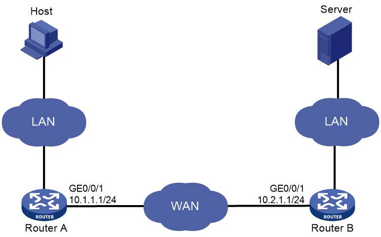
As shown in Figure 1, apply the predefined WAAS policy on Router A and Router B.
The host downloads data from the server. Examine the optimization effect by comparing DRE statistics for the first download and second download.
· For the first download, both WAAS devices create data dictionary entries and Router A sends both indexes and metadata.
· For the second download, Router A replaces repeated data with indexes.
Procedure
1. Configure IP addresses for interfaces. (Details not shown.)
2. Configure routing protocols to ensure connectivity. (Details not shown.)
3. Disable fast forwarding load sharing:
# Disable fast forwarding load sharing on Router A.
<RouterA> system-view
[RouterA] undo ip fast-forwarding load-sharing
# Disable fast forwarding load sharing on Router B.
<RouterB> system-view
[RouterB] undo ip fast-forwarding load-sharing
4. Apply the predefined WAAS policy to GigabitEthernet 1/0/1 on Router A.
[RouterA] interface gigabitethernet 1/0/1
[RouterA-GigabitEthernet1/0/1] waas apply policy
[RouterA-GigabitEthernet1/0/1] quit
[RouterA] quit
5. Apply the predefined WAAS policy to GigabitEthernet 1/0/1 on Router B.
[RouterB] interface gigabitethernet 1/0/1
[RouterB-GigabitEthernet1/0/1] waas apply policy
6. Download a test file of 14 MB from the server to the host.
7. Clear DRE statistics on Router A.
<RouterA> reset waas statistic dre
8. Download the same file from the server to the host.
Verifying the configuration
# After the first download, display DRE statistics on Router A.
<RouterA> display waas statistic dre
Peer-ID: cc3e-5fd8-5158
Peer version: 1.0
Cache in storage: 12710912 bytes
Index number: 49652
Age: 00 weeks, 00 days, 00 hours, 00 minutes, 35 seconds
Total connections: 1
Active connections: 0
Encode Statistics
Dre msgs: 2
Bytes in: 286 bytes
Bytes out: 318 bytes
Bypass bytes: 0 bytes
Bytes Matched: 0 bytes
Space saved: -11%
Average latency: 0 usec
Decode Statistics
Dre msgs: 57050
Bytes in: 14038391 bytes
Bytes out: 14079375 bytes
Bypass bytes: 0 bytes
Space saved: 0%
Average latency: 0 usec
# After the second download, display DRE statistics on Router A.
<RouterA> display waas statistic dre
Peer-ID: cc3e-5fd8-5158
Peer version: 1.0
Cache in storage: 12851200 bytes
Index number: 50200
Age: 00 weeks, 00 days, 00 hours, 2 minutes, 56 seconds
Total connections: 1
Active connections: 0
Encode Statistics
Dre msgs: 2
Bytes in: 286 bytes
Bytes out: 60 bytes
Bypass bytes: 0 bytes
Bytes Matched: 256 bytes
Space saved: 79%
Average latency: 0 usec
Decode Statistics
Dre msgs: 62791
Bytes in: 2618457 bytes
Bytes out: 13972208 bytes
Bypass bytes: 0 bytes
Space saved: 81%
Average latency: 0 usec
In the second download, the number of received bytes for decompression is much more smaller, and the download speed is much faster.
Example: Configuring a user-defined WAAS policy
Network configuration
As shown in Figure 2, configure and apply a user-defined WAAS policy on Router A and Router B.
The host downloads data from the server. Examine the optimization effect by comparing DRE statistics for the first download and second download.
· For the first download, both WAAS devices need to create data dictionary entries and Router A sends both indexes and metadata.
· For the second download, Router A replaces repeated data with indexes.

Procedure
1. Configure IP addresses for interfaces. (Details not shown.)
2. Configure routing protocols to ensure connectivity. (Details not shown.)
3. Disable fast forwarding load sharing:
# Disable fast forwarding load sharing on Router A.
<RouterA> system-view
[RouterA] undo ip fast-forwarding load-sharing
# Disable fast forwarding load sharing on Router B.
<RouterB> system-view
[RouterB] undo ip fast-forwarding load-sharing
4. Configure WAAS classes:
# Create a WAAS class named c1 on Router A, and configure the WAAS class to match any TCP packets.
[RouterA] waas class c1
[RouterA-waasclass-c1] match 1 tcp any
[RouterA-waasclass-c1] quit
# Create a WAAS class named c1 on Router B, and configure the WAAS class to match any TCP packets.
[RouterB] waas class c1
[RouterB-waasclass-c1] match tcp any
[RouterB-waasclass-c1] quit
5. Configure WAAS policies:
# Create a WAAS policy named p1 on Router A, and specify WAAS class c1. Configure TFO, DRE, and LZ optimization actions for the WAAS class.
[RouterA] waas policy p1
[RouterA-waaspolicy-p1] class c1
[RouterA-waaspolicy-p1-c1] optimize tfo dre lz
[RouterA-waaspolicy-p1-c1] quit
[RouterA-waaspolicy-p1] quit
# Create a WAAS policy named p1 on Router B, and specify WAAS class c1. Configure TFO, DRE, and LZ optimization actions for the WAAS class.
[RouterB] waas policy p1
[RouterB-waaspolicy-p1] class c1
[RouterB-waaspolicy-p1-c1] optimize tfo dre lz
[RouterB-waaspolicy-p1-c1] quit
[RouterB-waaspolicy-p1] quit
6. Apply WAAS policies:
# Apply WAAS policy p1 to GigabitEthernet 1/0/1 on Router A.
<RouterA> system-view
[RouterA] interface gigabitethernet 1/0/1
[RouterA-GigabitEthernet1/0/1] waas apply policy
[RouterA-GigabitEthernet1/0/1] quit
[RouterA] quit
# Apply WAAS policy p1 to GigabitEthernet 1/0/1 on Router B.
[RouterB] interface gigabitethernet 1/0/1
[RouterB-GigabitEthernet1/0/1] waas apply policy p1
[RouterB-GigabitEthernet1/0/1] quit
[RouterB] quit
7. Download a test file of 14 MB from the server to the host.
8. Clear DRE statistics on Router A.
<RouterA> reset waas statistic dre
9. Download the same file from the server to the host.
Verifying the configuration
# After the first download, display DRE statistics on Router A.
<RouterA> display waas statistic dre
Peer-ID: cc3e-5fd8-5158
Peer version: 1.0
Cache in storage: 12718592 bytes
Index number: 49682
Age: 00 weeks, 00 days, 00 hours, 00 minutes, 35 seconds
Total connections: 1
Active connections: 0
Encode Statistics
Dre msgs: 2
Bytes in: 286 bytes
Bytes out: 318 bytes
Bypass bytes: 0 bytes
Bytes Matched: 0 bytes
Space saved: -11%
Average latency: 0 usec
Decode Statistics
Dre msgs: 56959
Bytes in: 13999244 bytes
Bytes out: 14055291 bytes
Bypass bytes: 0 bytes
Space saved: 0%
Average latency: 0 usec
# After the second download, display DRE statistics on Router A.
<RouterA> display waas statistic dre
Peer-ID: cc3e-5fd8-5158
Peer version: 1.0
Cache in storage: 12857856 bytes
Index number: 50226
Age: 00 weeks, 00 days, 00 hours, 2 minutes, 02 seconds
Total connections: 1
Active connections: 0
Encode Statistics
Dre msgs: 2
Bytes in: 286 bytes
Bytes out: 60 bytes
Bypass bytes: 0 bytes
Bytes Matched: 256 bytes
Space saved: 79%
Average latency: 0 usec
Decode Statistics
Dre msgs: 62687
Bytes in: 2592183 bytes
Bytes out: 13972208 bytes
Bypass bytes: 0 bytes
Space saved: 81%
Average latency: 0 usec
In the second download, the number of received bytes for decompression is much more smaller, and the download speed is much faster.