- Table of Contents
-
- 07-Layer 3—IP Services Configuration Guide
- 00-Preface
- 01-ARP configuration
- 02-IP addressing configuration
- 03-DHCP configuration
- 04-DNS configuration
- 05-HTTP configuration
- 06-IP forwarding basics configuration
- 07-Fast forwarding configuration
- 08-Adjacency table configuration
- 09-IRDP configuration
- 10-IP performance optimization configuration
- 11-UDP helper configuration
- 12-IPv6 basics configuration
- 13-IPv6 neighbor discovery configuration
- 14-DHCPv6 configuration
- 15-IPv6 fast forwarding configuration
- 16-WAAS configuration
- 17-HTTP redirect configuration
- 18-Web caching configuration
- Related Documents
-
| Title | Size | Download |
|---|---|---|
| 13-IPv6 neighbor discovery configuration | 402.85 KB |
Configuring IPv6 neighbor discovery
ICMPv6 messages used by IPv6 neighbor discovery
Neighbor reachability detection
Router/prefix discovery and stateless address autoconfiguration
IPv6 neighbor discovery tasks at a glance
Configuring a static neighbor entry
Setting the dynamic neighbor learning limit
Enabling unsolicited NA learning
Setting the aging timer for ND entries in stale state
Setting ND entry probing parameters
Minimizing link-local ND entries
Enabling recording ND entry learning events
Configuring RA message sending and parameters
Enabling the sending of RA messages
Configuring parameters for RA messages
Specifying DNS server information in RA messages
Specifying DNS suffix information in RA messages
Suppressing advertising DNS information in RA messages
Enabling advertising invalid delegated prefixes
Setting the maximum number of attempts to send an NS message for DAD
Enabling duplicate detection for duplicate addresses
Enabling cross-segment ND proxy
Configuring a customer-side or a network-side port
Configuring IPv6 ND suppression
Configuring IPv6 ND direct route advertisement
About IPv6 ND direct route advertisement
Application in Layer 3 access networks
Enabling recording user IPv6 address conflicts
Enabling recording user port migrations
Enabling ND logging for user online and offline events
Enabling unique ND entry learning for IPv6 addresses
Disabling sending NS messages when data packets trigger ND resolution
Using ND-ping to verify the availability of an IPv6 address
Using ND-Ping to obtain the IPv6 address for a MAC address
Verifying and maintaining IPv6 ND
Displaying brief ND log information
Displaying and clearing IPv6 neighbor information
Displaying and clearing ND suppression entries
Displaying statistics about ND proxy reply packets
Displaying information about ND direct route advertisement
IPv6 ND configuration examples
Example: Configuring IPv6 ND suppression
Configuring IPv6 neighbor discovery
About IPv6 neighbor discovery
ICMPv6 messages used by IPv6 neighbor discovery
The IPv6 neighbor discovery (ND) process uses ICMP messages for address resolution, neighbor reachability verification, and neighboring device tracking.
Table 1 describes the ICMPv6 messages used by the IPv6 ND protocol.
Table 1 ICMPv6 messages used by ND
|
ICMPv6 message |
Type |
Function |
|
Neighbor Solicitation (NS) |
135 |
Acquires the link-layer address of a neighbor on the local link. |
|
Verifies the reachability of a neighbor. |
||
|
Detects duplicate addresses. |
||
|
Neighbor Advertisement (NA) |
136 |
Responds to an NS message. |
|
Notifies the neighboring nodes of link layer changes. |
||
|
Router Solicitation (RS) |
133 |
Requests an address prefix and other configuration information for autoconfiguration after startup. |
|
Router Advertisement (RA) |
134 |
Responds to an RS message. |
|
Advertises information, such as the Prefix Information options and flag bits. |
||
|
Redirect |
137 |
Informs the source host of a better next hop on the path to a particular destination when certain conditions are met. |
Address resolution
This function is similar to ARP in IPv4. An IPv6 node acquires the link-layer addresses of neighboring nodes on the same link through NS and NA messages.
Figure 1 shows how Host A acquires the link-layer address of Host B on the same link. The address resolution procedure is as follows:
1. Host A multicasts an NS message. The source address of the NS message is the IPv6 address of the sending interface of Host A. The destination address is the solicited-node multicast address of Host B. The NS message body contains the link-layer address of Host A and the target IPv6 address.
2. After receiving the NS message, Host B determines whether the target address of the packet is its IPv6 address. If it is, Host B learns the link-layer address of Host A, and then unicasts an NA message containing its link-layer address.
3. Host A acquires the link-layer address of Host B from the NA message.

Neighbor reachability detection
After Host A acquires the link-layer address of its neighbor Host B, Host A can use NS and NA messages to test the reachability of Host B as follows:
1. Host A sends an NS message whose destination address is the IPv6 address of Host B.
2. If Host A receives an NA message from Host B, Host A decides that Host B is reachable. Otherwise, Host B is unreachable.
Duplicate address detection
After Host A acquires an IPv6 address, it performs Duplicate Address Detection (DAD) to check whether the address is being used by any other node. This is similar to gratuitous ARP in IPv4. DAD is accomplished through NS and NA messages.
The DAD procedure is as follows:
1. Host A sends an NS message. The source address is the unspecified address and the destination address is the corresponding solicited-node multicast address of the IPv6 address to be detected. The NS message body contains the detected IPv6 address.
2. If Host B uses this IPv6 address, Host B returns an NA message that contains its IPv6 address.
3. Host A knows that the IPv6 address is being used by Host B after receiving the NA message from Host B. If receiving no NA message, Host A decides that the IPv6 address is not in use and uses this address.
Figure 2 Duplicate address detection

Router/prefix discovery and stateless address autoconfiguration
Router/prefix discovery allows an IPv6 node to find the neighboring routers and learn the prefix and network configuration parameters of the network from receiving RA messages.
Stateless address autoconfiguration allows an IPv6 node to automatically generate an IPv6 address based on the information learned through router/prefix discovery.
A node performs router/prefix discovery and stateless address autoconfiguration as follows:
1. At startup, a node sends an RS message to request configuration information from a router.
2. The router returns an RA message containing the Prefix Information option and other configuration information. (The router also periodically sends an RA message.)
3. The node automatically generates an IPv6 address and other configuration parameters according to the configuration information in the RA message.
The Prefix Information option contains an address prefix and the preferred lifetime and valid lifetime of the address prefix. A node updates the preferred lifetime and valid lifetime upon receiving a periodic RA message.
The generated IPv6 address is valid within the valid lifetime and becomes invalid when the valid lifetime expires.
After the preferred lifetime expires, the node cannot use the generated IPv6 address to establish new connections, but can receive packets destined for the IPv6 address. The preferred lifetime cannot be greater than the valid lifetime.
Redirection
Upon receiving a packet from a host, the gateway sends an ICMPv6 redirect message to inform the host of a better next hop when the following conditions are met:
· The interface receiving the packet is the same as the interface forwarding the packet.
· The selected route is not created or modified by an ICMPv6 redirect message.
· The selected route is not a default route on the device.
Protocols and standards
· RFC 4861, Neighbor Discovery for IP Version 6 (IPv6)
· RFC 8106, IPv6 Router Advertisement Options for DNS Configuration
IPv6 neighbor discovery tasks at a glance
All IPv6 neighbor discovery tasks are optional.
· Configuring ND entry related features
¡ Configuring a static neighbor entry
¡ Setting the dynamic neighbor learning limit
¡ Enabling unsolicited NA learning
¡ Setting the aging timer for ND entries in stale state
¡ Setting ND entry probing parameters
¡ Minimizing link-local ND entries
¡ Enabling recording ND entry learning events
· Configuring RA message sending and parameters
· Enabling advertising invalid delegated prefixes
· Setting the maximum number of attempts to send an NS message for DAD
· Enabling duplicate detection for duplicate addresses
¡ Enabling cross-segment ND proxy
· Configuring a customer-side or a network-side port
· Configuring IPv6 ND suppression
· Configuring IPv6 ND direct route advertisement
· Configuring user information recording
¡ Enabling recording user IPv6 address conflicts
¡ Enabling recording user port migrations
¡ Enabling ND logging for user online and offline events
· Enabling unique ND entry learning for IPv6 addresses
· Disabling sending NS messages when data packets trigger ND resolution
Configuring a static neighbor entry
About this task
A neighbor entry stores information about a link-local node. The entry can be created dynamically through NS and NA messages, or configured statically.
The device uniquely identifies a static neighbor entry by using the neighbor's IPv6 address and the number of the Layer 3 interface that connects to the neighbor. You can configure a static neighbor entry by using one of the following methods:
· Method 1—Associate a neighbor's IPv6 address and link-layer address with the local Layer 3 interface.
· Method 2—Associate a neighbor's IPv6 address and link-layer address with a Layer 2 port in a VLAN.
Restrictions and guidelines
To configure a static neighbor entry for a VLAN interface, use Method 1 or Method 2.
· If you use Method 1, the device is required to resolve the Layer 2 port in the related VLAN.
· If you use Method 2, make sure the Layer 2 port belongs to the specified VLAN and the corresponding VLAN interface already exists. After the configuration, the device associates the VLAN interface with the neighbor IPv6 address to identify the static neighbor entry.
To delete a neighbor entry for a VLAN interface, specify only the VLAN interface.
Procedure
1. Enter system view.
system-view
2. Configure a static neighbor entry.
ipv6 neighbor ipv6-address mac-address { vlan-id port-type port-number | interface interface-type interface-number } [ vpn-instance vpn-instance-name ]
By default, no static neighbor entries exist.
Setting the dynamic neighbor learning limit
About this task
The device can dynamically acquire the link-layer address of a neighboring node through NS and NA messages and add it into the neighbor table. A large neighbor table degrades the forwarding performance. To avoid excessive resource consumption by neighbor entries, use one of the following methods:
· Set the maximum number of dynamic neighbor entries that an interface can learn. When the number of dynamic neighbor entries reaches the limit, the interface stops learning neighbor information.
· Set the maximum number of dynamic neighbor entries that the device can learn. When the number of dynamic neighbor entries reaches the limit, the device stops learning neighbor information.
The number of dynamic neighbor entries learnt by the interfaces on a device cannot exceed the maximum number of dynamic neighbor entries that the device can learn.
Setting the maximum number of dynamic neighbor entries on an interface
1. Enter system view.
system-view
2. Enter interface view.
interface interface-type interface-number
3. Set the dynamic neighbor learning limit on the interface.
ipv6 neighbors max-learning-num max-number
The default setting varies by device model. For more information about the default settings on the devices, see the command reference.
Setting the maximum number of dynamic neighbor entries on the device
1. Enter system view.
system-view
2. Set the dynamic neighbor learning limit on the device.
ipv6 neighbors max-learning-number max-number slot slot-number
The default setting varies by device model.
To disable the device from learning dynamic neighbor entries, set the value for the max-number argument to 0.
Enabling unsolicited NA learning
About this task
On some networks, a server multicasts NA messages to two peer devices for link backup. The peer devices cannot learn ND entry for the server from these NA messages by default. If no ND learning is triggered by data exchange between the server and peer devices, the peer devices learn the entry for the server only when the server unicasts messages to them.
This feature enables an interface to learn ND entries from unsolicited NA messages. The ND entries generated by using this method are in stale state.
Restrictions and guidelines
To ensure that the device learns ND entries from trusted NA messages, enable this feature only on a secure network.
This feature might cause the device to learn excessive ND entries that consume too many system resources. As a best practice, execute the ipv6 neighbor stale-aging command to set a smaller aging timer before you enable this feature. The smaller aging timer accelerates the aging of ND entries in stale state.
This feature is available only on Layer 3 interfaces.
Procedure
1. Enter system view.
system-view
2. Enter Layer 3 interface view.
interface interface-type interface-number
3. Enable unsolicited NA learning.
ipv6 nd unsolicited-na-learning enable
By default, unsolicited NA learning is disabled.
Setting the aging timer for ND entries in stale state
About this task
ND entries in stale state have an aging timer. If an ND entry in stale state is not refreshed before the timer expires, the ND entry changes to the delay state. If it is still not refreshed in 5 seconds, the ND entry changes to the probe state, and the device sends an NS message three times. If no response is received, the device deletes the ND entry.
Restrictions and guidelines
You can set the aging timer for ND entries in stale state in system view and interface view. For ND entries in stale state on an interface, the aging timer in interface view has priority over the aging timer in system view.
Procedure
1. Enter system view.
system-view
2. Set the aging timer for ND entries in stale state.
¡ Set the aging timer for ND entries in stale state in system view.
ipv6 neighbor stale-aging { aging-minutes | second aging-seconds }
The default setting is 240 minutes.
¡ Execute the following commands in sequence to set the aging timer in interface view.
interface interface-type interface-number
ipv6 neighbor timer stale-aging { aging-minutes | second aging-seconds }
By default, the aging timer of ND entries in stale state is not configured on an interface. The aging timer is determined by the configuration of this command in system view.
Setting ND entry probing parameters
About this task
After an ND entry changes to PROBE state, the device sends an NS message to test the reachability of the neighbor in the ND entry. A maximum of three attempts is allowed by default. The device handles the ND entry as follows:
· If the device does not receive an NA message from the neighbor, it deletes the ND entry.
· If the device receives an NA message from the neighbor, it sets the ND entry state to REACHABLE.
Perform this task to set the maximum number of probes and the probe interval for ND entries.
Restrictions and guidelines
When you modify the probe count, the modification does not take effect on ND entries in PROBE state. Neighbor entries in DELAY state will adopt this setting when they enter into the PROBE state.
When you modify the probe interval, the modification takes effect immediately.
Procedure
1. Enter system view.
system-view
2. Set the maximum number of probes to test the reachability of neighbors in ND entries.
ipv6 neighbor aging probe-count count
By default, the device performs a maximum of three probes to test the reachability of neighbors in ND entries.
3. Set the interval for testing the reachability of neighbors in ND entries.
ipv6 neighbor aging probe-interval interval
By default, the interval for testing the reachability of neighbors in ND entries is the same as the interval for retransmitting an NS message.
Minimizing link-local ND entries
About this task
Perform this task to minimize link-local ND entries assigned to the hardware. Link-local ND entries refer to ND entries that contain link-local addresses.
By default, the device assigns all ND entries to the hardware. With this feature enabled, the newly learned link-local ND entries are not assigned to the hardware if the link-local addresses of the entries are not the next hops of any routes. This feature saves hardware resources.
This feature takes effect only on newly learned link-local ND entries.
Procedure
1. Enter system view.
system-view
2. Minimize link-local ND entries.
ipv6 neighbor link-local minimize
By default, the device assigns all ND entries to the hardware.
Enabling recording ND entry learning events
About this task
An ND entry learning event occurs when the number of ND entries that a card or an interface has learnt exceeds the threshold or drops below the threshold.
After you enable this feature, the ND module logs ND entry learning events and sends them to the information center. For log messages to be sent correctly, configure the information center to set log message filtering and output rules, including output destinations. For information about the log destination and output rule configuration in the information center, see information center configuration in Network Management and Monitoring Configuration Guide.
If you enable ND entry limit notifications for the ND module, the device sends a notification to the SNMP module when the number of ND entries exceeds the alarm threshold. For ND entry limit notifications to be sent correctly, you must also configure SNMP on the device.
For more information about SNMP configuration, see SNMP configuration in Network Management and Monitoring Configuration Guide. For more information about ND entry limit notifications, see ND attack defense configuration in Security Configuration Guide.
Procedure
1. Enter system view.
system-view
2. (Optional.) Enable SNMP notifications for the ND module.
snmp-agent trap enable nd [ entry-limit ]
By default, SNMP notifications are disabled for the ND module.
If you do not specify a keyword, this command enables all types of SNMP notifications for the ND module. If you specify the entry-limit keyword, this command enables only ND entry limit notifications for the ND module.
3. Enable recording ND entry learning events.
ipv6 nd entry-limit record enable
By default, the ND module does not record ND entry learning events.
Setting the hop limit
About this task
You can set the hop limit value to fill in the Hop Limit field for IPv6 packets to be sent.
Procedure
1. Enter system view.
system-view
2. Set the value for the Hop Limit field in the IP header.
ipv6 hop-limit value
The default setting is 64.
Configuring RA message sending and parameters
About RA message parameters
You can enable an interface to send RA messages, and configure the interval for sending RA messages and parameters in RA messages. After receiving an RA message, a host can use these parameters to perform corresponding operations. Table 2 describes the configurable parameters in an RA message.
Table 2 Parameters in an RA message and their descriptions
|
Parameter |
Description |
|
Hop Limit |
Maximum number of hops in RA messages. A host receiving the RA message fills the value in the Hop Limit field of sent IPv6 packets. |
|
Prefix information |
After receiving the prefix information, the hosts on the same link can perform stateless autoconfiguration. |
|
MTU |
Guarantees that all nodes on the link use the same MTU. |
|
M flag |
Determines whether a host uses stateful autoconfiguration to obtain an IPv6 address. If the M flag is set to 1, the host uses stateful autoconfiguration (for example, from a DHCPv6 server) to obtain an IPv6 address. Otherwise, the host uses stateless autoconfiguration to generate an IPv6 address according to its link-layer address and the prefix information in the RA message. |
|
O flag |
Determines whether a host uses stateful autoconfiguration to obtain configuration information other than the IPv6 address. If the O flag is set to 1, the host uses stateful autoconfiguration (for example, from a DHCPv6 server) to obtain configuration information other than the IPv6 address. Otherwise, the host uses stateless autoconfiguration. |
|
Router Lifetime |
Tells the receiving hosts how long the advertising router can live. If the lifetime of a router is 0, the router cannot be used as the default gateway. |
|
Retrans Timer |
If the device does not receive a response message within the specified time after sending an NS message, it retransmits the NS message. |
|
Reachable Time |
If the neighbor reachability detection shows that a neighbor is reachable, the device considers the neighbor reachable within the specified reachable time. If the device needs to send a packet to the neighbor after the specified reachable time expires, the device reconfirms whether the neighbor is reachable. |
|
Router Preference |
Specifies the router preference in an RA message. A host selects a router as the default gateway according to the router preference. If router preferences are the same, the host selects the router from which the first RA message is received. |
|
DNS server option |
DNS server information for IPv6 hosts. Hosts can obtain DNS server information from received RA messages instead of using DHCPv6. |
|
DNS suffix information in DNS Search List (DNSSL) option |
DNS suffix information for IPv6 hosts. Hosts can obtain DNS suffix information from received RA messages instead of using DHCPv6. |
Restrictions and guidelines
The maximum interval for sending RA messages should be less than (or equal to) the router lifetime in RA messages. In this way, the router can be updated by an RA message before expiration.
The values of the NS retransmission timer and the reachable time configured for an interface are sent in RA messages to hosts. This interface sends NS messages at the interval of the NS retransmission timer and considers a neighbor reachable within the reachable time.
Enabling the sending of RA messages
1. Enter system view.
system-view
2. Enter interface view.
interface interface-type interface-number
3. Enable the sending of RA messages.
undo ipv6 nd ra halt
The default setting is disabled.
4. Set the maximum and minimum intervals for sending RA messages.
ipv6 nd ra interval max-interval min-interval
By default, the maximum interval for sending RA messages is 600 seconds, and the minimum interval is 200 seconds.
The device sends RA messages at random intervals between the maximum interval and the minimum interval.
The minimum interval should be less than or equal to 0.75 times the maximum interval.
Configuring parameters for RA messages
1. Enter system view.
system-view
2. Enter interface view.
interface interface-type interface-number
3. Configure the prefix information in RA messages.
ipv6 nd ra prefix { ipv6-prefix prefix-length | ipv6-prefix/prefix-length } [ valid-lifetime preferred-lifetime [ no-autoconfig | off-link | prefix-preference level ] * | no-advertise ]
By default, no prefix information is configured for RA messages, and the IPv6 address of the interface sending RA messages is used as the prefix information. If the IPv6 address is manually configured, the prefix uses a fixed valid lifetime of 2592000 seconds (30 days) and a preferred lifetime of 604800 seconds (7 days). If the IPv6 address is automatically obtained, the prefix uses the valid lifetime and preferred lifetime configured for the IPv6 address.
4. Configure the default settings for prefixes advertised in RA messages.
ipv6 nd ra prefix default [ valid-lifetime preferred-lifetime [ no-autoconfig | off-link | prefix-preference level ] * | no-advertise ]
By default, no default settings are configured for prefixes advertised in RA messages.
5. Turn off the MTU option in RA messages.
ipv6 nd ra no-advlinkmtu
By default, RA messages contain the MTU option.
6. Specify unlimited hops in RA messages.
ipv6 nd ra hop-limit unspecified
By default, the maximum number of hops in RA messages is 64.
7. Specify the URL of the boot file in RA messages.
ipv6 nd ra boot-file-url url-string
By default, RA messages do not contain the URL of the boot file.
8. Set the M flag bit to 1.
ipv6 nd autoconfig managed-address-flag
By default, the M flag bit is set to 0 in RA advertisements. Hosts receiving the advertisements will obtain IPv6 addresses through stateless autoconfiguration.
9. Set the O flag bit to 1.
ipv6 nd autoconfig other-flag
By default, the O flag bit is set to 0 in RA advertisements. Hosts receiving the advertisements will acquire other configuration information through stateless autoconfiguration.
10. Set the router lifetime in RA messages.
ipv6 nd ra router-lifetime time
By default, the router lifetime is three times as long as the maximum interval for advertising RA messages.
11. Set the NS retransmission timer.
ipv6 nd ns retrans-timer value
By default, an interface sends NS messages every 1000 milliseconds, and the value of the Retrans Timer field in RA messages is 0.
12. Set the router preference in RA messages.
ipv6 nd router-preference { high | low | medium }
By default, the router preference is medium.
13. Set the reachable time.
ipv6 nd nud reachable-time time
By default, the neighbor reachable time is 1200000 milliseconds, and the value of the Reachable Time field in sent RA messages is 0.
Specifying DNS server information in RA messages
About this task
The DNS server options in RA messages provide DNS server information for IPv6 hosts. The RA messages allow hosts to obtain their IPv6 addresses and the DNS server through stateless autoconfiguration. This method is useful in a network where DHCPv6 infrastructure is not provided.
One DNS server option contains one DNS server. All DNS server options are sorted in ascending order of the DNS server sequence number.
After you execute the ipv6 nd ra dns server command, the device immediately sends an RA message with the existing and newly specified DNS server information.
After you execute the undo ipv6 nd ra dns server command, the device immediately sends two RA messages.
· The first RA message contains information about all DNS servers, including the DNS servers specified in the undo command with their lifetime set to 0 seconds.
· The second RA message contains information about remaining DNS servers.
Each time the device sends an RA message from an interface, it immediately refreshes the RA message advertisement interval for that interface.
Restrictions and guidelines
You can configure a maximum of eight DNS servers on an interface.
The default lifetime of a DNS server is three times the maximum interval for advertising RA messages. To set the maximum interval, use the ipv6 nd ra interval command.
In an IPv6 environment, PPP users can obtain the IPv6 DNS server address through AAA authorization. This AAA-authorized IPv6 DNS server address is delivered in RA messages to the users.If an interface obtains the AAA-authorized and manually specified IPv6 DNS server addresses, the RA messages contain both, with the AAA-authorized address in the front. When the two addresses conflict, the AAA-authorized DNS address is used.
For more information about the PPP support for IPv6, see PPP configuration in Layer 2—WAN Access Configuration Guide.
Procedure
1. Enter system view.
system-view
2. Enter interface view.
interface interface-type interface-number
3. Specify DNS server information to be advertised in RA messages.
ipv6 nd ra dns server ipv6-address [ seconds | infinite ] sequence seqno
By default, no DNS server information is specified and RA messages do not contain DNS server options.
Specifying DNS suffix information in RA messages
About this task
The DNSSL option in RA messages provides suffix information for IPv6 hosts. The RA messages allow hosts to obtain their IPv6 addresses and the DNS suffix through stateless autoconfiguration. This method is useful in a network where DHCPv6 infrastructure is not provided.
One DNSSL option contains one DNS suffix. All DNSSL options are sorted in ascending order of the sequence number of the DNS suffix.
After you execute the ipv6 nd ra dns search-list command, the device immediately sends an RA message with the existing and newly specified DNS suffix information.
After you execute the undo ipv6 nd ra dns search-list command, the device immediately sends two RA messages.
· The first RA message contains information about all DNS suffixes, including DNS suffixes specified in the undo command with their lifetime set to 0 seconds.
· The second RA message contains information about remaining DNS suffixes.
Each time the device sends an RA message from an interface, it immediately refreshes the RA message advertisement interval for that interface.
Restrictions and guidelines
You can configure a maximum of eight DNS suffixes on an interface.
The default lifetime of a DNS suffix is three times the maximum interval for advertising RA messages. To set the maximum interval, use the ipv6 nd ra interval command.
Procedure
1. Enter system view.
system-view
2. Enter interface view.
interface interface-type interface-number
3. Specify DNS suffix information to be advertised in RA messages.
ipv6 nd ra dns search-list domain-name [ seconds | infinite ] sequence seqno
By default, no DNS suffix information is specified and RA messages do not contain DNS suffix options.
Suppressing advertising DNS information in RA messages
About this task
Perform this task to suppress the device from advertising information about DNS server addresses and DNS suffixes in RA messages.
Whether enabling this feature on an interface will trigger sending RA message immediately depends on the interface configuration:
· If the interface has DNS server information configured or has obtained an AAA-authorized DNS server address, the device immediately sends two RA messages. In the first message, the lifetime for DNS server addresses is 0 seconds. The second RA message does not contain any DNS server options.
· If the interface has no DNS server information specified or no AAA-authorized DNS server address assigned, no RA messages are triggered.
If you specify a new DNS server or remove a DNS server on the interface after enabling DNS server suppression, the device immediately sends an RA message without any DNS server options.
Whether disabling this feature on an interface will trigger sending RA message immediately depends on the interface configuration:
· If the interface has DNS server information configured or has obtained an AAA-authorized DNS server address, the device immediately sends an RA message containing the DNS server information.
· If the interface has no DNS server information specified or no AAA-authorized DNS server address assigned, no RA messages are triggered.
Each time the device sends an RA message from an interface, it immediately refreshes the RA message advertisement interval for that interface.
The same suppression mechanism applies when you enable or disable DNS suffix suppression in RA messages.
Procedure
1. Enter system view.
system-view
2. Enter interface view.
interface interface-type interface-number
3. Enable DNS server suppression in RA messages.
ipv6 nd ra dns server suppress
By default, DNS server suppression in RA messages is disabled.
4. Enable DNS suffix suppression in RA messages.
ipv6 nd ra dns search-list suppress
By default, DNS suffix suppression in RA messages is disabled.
Enabling advertising invalid delegated prefixes
About this task
An interface can generate an IPv6 address based on a prefix, which is assigned by the DHCPv6 server. When the assigned prefix goes invalid, the device does not advertise RA messages for the event by default. In this case, endpoints that use this prefix are not aware of the event, and continue using the IPv6 addresses generated based on the prefix, causing communication failures. To avoid this problem, you can use this feature.
When a DHCPv6 server-assigned prefix goes invalid, the device sends out RA messages immediately. The device sets both the preferred lifetime and valid lifetime to 0 in these messages, announcing that the prefix is invalid. Upon receiving the advertisement, endpoints will no longer use the IPv6 addresses generated based on the prefix. For more information about DHCPv6, see DHCPv6 configuration in Layer 3—IP Services Configuration Guide.
Restrictions and guidelines
RA message advertisement is suppressed by default. To disable RA message suppression, use the undo ipv6 nd ra halt command.
Procedure
1. Enter system view.
system-view
2. Enter interface view.
interface interface-type interface-number
3. Enable advertising invalid delegated prefixes.
ipv6 nd ra invalid-delegated-prefix advertise enable
By default, advertising invalid delegated prefixes is disabled.
Setting the maximum number of attempts to send an NS message for DAD
About this task
An interface sends an NS message for DAD for an obtained IPv6 address. The interface resends the NS message if it does not receive a response within the time specified by the ipv6 nd ns retrans-timer command. If the interface receives no response after making the maximum attempts specified by the ipv6 nd dad attempts command, the interface uses the IPv6 address.
Procedure
1. Enter system view.
system-view
2. Enter interface view.
interface interface-type interface-number
3. Set the number of attempts to send an NS message for DAD.
ipv6 nd dad attempts times
The default setting is 1. When the times argument is set to 0, DAD is disabled.
Enabling duplicate detection for duplicate addresses
About this task
If the device detects that an IPv6 address on an interface has been used on the network, the device marks that IPv6 address as duplicate. The interface cannot use the address for communication.
By default, an interface does not perform duplicate detection for duplicate addresses. Once an IPv6 address is marked as duplicate on an interface, it will be unusable even after it becomes unique on the link later.
To resolve this issue, enable duplicate detection for duplicate addresses. This feature sends NS messages to the duplicate address at random intervals until it does not receive an NA response message from that address or until duplicate detection is disabled for duplicate addresses. For more information about the detection process, see "Duplicate address detection."
You can set the maximum duplicate detection interval for duplicate addresses. After the device marks a detected address as duplicate, it waits for a random amount of time between 1 and the maximum detection interval. Then, the device resends an NS message to the solicited-node multicast address of the duplicate address. This mechanism helps reduce the risk of congestion that results from the NS messages sent for duplicate detection.
Procedure
1. Enter system view.
system-view
2. Enable duplicate detection for duplicate addresses.
ipv6 address duplicate-detect enable
By default, duplicate detection is disabled for duplicate addresses.
3. (Optional.) Set the maximum duplicate detection interval for duplicate addresses.
ipv6 address duplicate-detect interval interval
The default maximum interval is 5 seconds.
Enabling ND proxy
About ND proxy
ND proxy enables a device to answer an NS message requesting the hardware address of a host on another network. With ND proxy, hosts in different broadcast domains can communicate with each other as they would on the same network.
ND proxy includes common ND proxy, cross-segment ND proxy, and local ND proxy.
Common ND proxy
As shown in Figure 3, Interface A with IPv6 address 4:1::99/64 and Interface B with IPv6 address 4:2::99/64 belong to different subnets. Host A and Host B reside on the same network but in different broadcast domains.
Figure 3 Application environment of ND proxy

Because Host A's IPv6 address is on the same subnet as Host B's, Host A directly sends an NS message to obtain Host B's MAC address. However, Host B cannot receive the NS message because they belong to different broadcast domains.
To solve this problem, enable common ND proxy on Interface A and Interface B of the device. The device replies to the NS message from Host A, and forwards packets from other hosts to Host B.
Cross-segment ND proxy
As shown in Figure 4, Interface A with IPv6 address 4:2::1/126 and Interface B with IPv6 address 4:3::1/126 belong to different subnets. Host A and Host B reside on the same network but in different broadcast domains.
Figure 4 Application environment of cross-segment ND proxy

Because Host A's IPv6 address is on the same subnet as Host B's, Host A directly sends an NS message to obtain Host B's MAC address. However, Host B cannot receive the NS message because they belong to different broadcast domains. The device cannot receive the NS messages sent by Host A and Host B because IPv6 addresses of Interface A and Interface B are in different subnets.
To solve this problem, enable cross-segment ND proxy on Interface A and Interface B of the device. The device replies to the NS messages from Host A and Host B, and forwards packets from other hosts to Host A and Host B.
Local ND proxy
As shown in Figure 5, Host A belongs to VLAN 2 and Host B belongs to VLAN 3. Host A and Host B connect to Port B1 and Port B3, respectively.
Figure 5 Application environment of local ND proxy
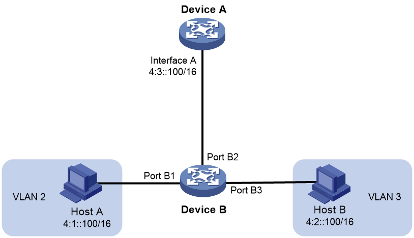
Because Host A's IPv6 address is on the same subnet as Host B's, Host A directly sends an NS message to obtain Host B's MAC address. However, Host B cannot receive the NS message because they belong to different VLANs.
To solve this problem, enable local ND proxy on Interface A of Device A so that Device A can forward messages between Host A and Host B.
Local ND proxy implements Layer 3 communication for two hosts in the following cases:
· The two hosts connect to ports of the same device and the ports must be in different VLANs.
· The two hosts connect to isolated Layer 2 ports in the same isolation group of a VLAN.
· If super VLAN is used, the two hosts must belong to different sub VLANs.
Enabling common ND proxy
1. Enter system view.
system-view
2. Enter interface view.
interface interface-type interface-number
3. Enable common ND proxy.
proxy-nd enable
By default, common ND proxy is disabled.
Enabling cross-segment ND proxy
1. Enter system view.
system-view
2. Enter interface view.
interface interface-type interface-number
3. Enable cross-segment ND proxy.
proxy-nd span-segment enable
By default, cross-segment ND proxy is disabled.
Enabling local ND proxy
1. Enter system view.
system-view
2. Enter interface view.
interface interface-type interface-number
3. Enable local ND proxy.
local-proxy-nd enable
By default, local ND proxy is disabled.
Configuring a customer-side or a network-side port
About this task
By default, the device associates an ND entry with routing information when the device learns an ND entry. The ND entry provides the next hop information for routing. To save hardware resources, you can use this command to specify a port that connects a user terminal as a customer-side port. The device will not associate the routing information with the learned ND entries.
Procedure
1. Enter system view.
system-view
2. Create a VLAN interface and enter VLAN interface view.
interface vlan-interface vlan-interface-id
3. Specify the interface as a customer-side or network-side port.
¡ Specify the interface as a customer-side port.
ipv6 nd mode uni
¡ Specify the interface as a network-side port.
undo ipv6 nd mode
By default, a port acts as a network-side port.
Configuring IPv6 ND suppression
About this task
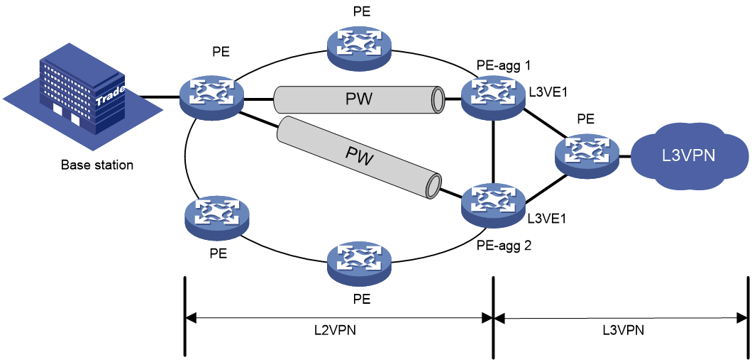
The ND suppression feature enables a device to directly answer ND requests by using ND suppression entries. The device generates ND suppression entries based on dynamic ND entries that it learns. This feature is typically configured on the PEs connected to base stations in an L2VPN that provides access to an L3VPN network.
You can also configure the ND suppression push feature to push ND suppression entries at intervals by advertising NA messages.
Figure 6 shows a typical application scenario. ND suppression is enabled on the PE that connects to the base station. The PE generates ND suppression entries for the base station, PE-agg 1, and PE-agg 2, and it directly replies to subsequent ND requests for these devices.
Procedure
1. Enter system view.
system-view
2. Configure a cross-connect group and enter its view.
xconnect-group group-name
By default, no cross-connect groups exist.
For more information about the command, see the MPLS L2VPN commands in MPLS Command Reference.
3. Configure a cross-connect and enter it view.
connection connection-name
For more information about the command, see the MPLS L2VPN commands in MPLS Command Reference.
4. Enable IPv6 ND suppression.
ipv6 nd suppression enable
By default, the IPv6 ND suppression feature is disabled.
5. Quit cross-connect view.
quit
6. Quit cross-connect group view.
quit
7. (Optional.) Enable the suppression push feature and set a push interval.
ipv6 nd suppression push interval interval
By default, the ND suppression push feature is disabled.
Configuring IPv6 ND direct route advertisement
About IPv6 ND direct route advertisement
This feature generates 128-bit host routes based on ND entries for packet forwarding and route advertisement. The route preference value determines the match order of a route. Dynamic routing protocols use the tag value as the route identifier when redistributing the route.
After you enable this feature, the routing table might be populated with excessive host routes. To reduce the routing table size, execute the ipv6 nd route-direct prefix convert-length command for the device to generate network routes for identified ND entries and delete the corresponding host routes.
In scenarios where both network routes and host routes are required, specify the retain-host-route keyword to retain the generated host routes when you execute the ipv6 nd route-direct prefix convert-length command. In other scenarios, to avoid a large number of host routes, do not specify the retain-host-route keyword.
After you enable ND direct route advertisement on an interface, the device generates direct routes and adjacency table entries based on ND entries learned on that interface. If the direct routes are generated before the adjacency table entries, temporary packet loss will occur due to lack of Layer 2 information for packet encapsulation. To avoid such an issue, set a route generation delay for ND direct route advertisement on the interface.
If you edit the direct route advertisement configuration before the delay timer expires, the device advertises the direct route based on the new configuration immediately.
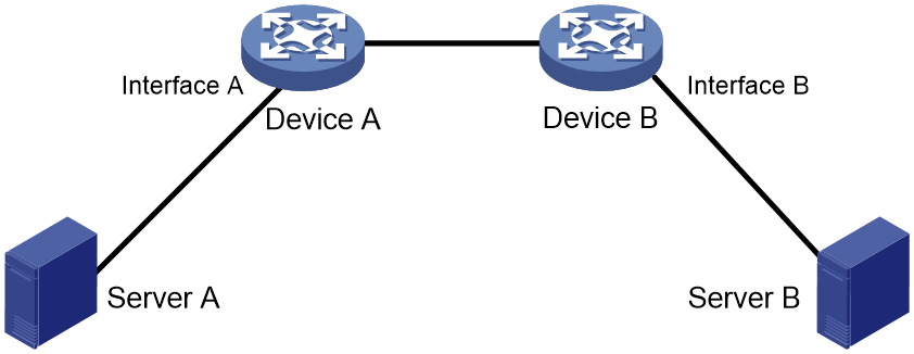
Application in Layer 3 access networks
As shown in Figure 7, ND direct route advertisement is enabled on Interface A and Interface B. This feature generates a host route to Server A and a host route to Server B for the routing protocols to advertise. So each device forwards only the traffic destined to the server within the network, which saves bandwidth.
Figure 7 Application in a Layer 3 access network
Procedure
1. Enter system view.
system-view
2. Enter interface view.
interface interface-type interface-number
3. (Optional.) Set the delay time for ND direct route generation.
ipv6 nd route-direct advertise delay delay-time
By default, the device does not delay ND direct route generation.
4. Enable ND direct route advertisement.
ipv6 nd route-direct advertise [ preference preference-value | tag tag-value ] *
By default, ND direct route advertisement is disabled.
5. (Optional.) Specify a prefix length for generating a network route for identified ND entries.
ipv6 nd route-direct prefix ipv6-prefix prefix-length convert-length convert-length [ retain-host-route ]
By default, no prefix length is specified for generating a network route for identified ND entries.
For the configuration to take effect, the specified IPv6 prefix must be consistent with the IPv6 address prefix of the interface.
Enabling recording user IPv6 address conflicts
About this task
This feature detects and records user IPv6 address conflicts. A conflict occurs if an incoming NA packet has the same source IP address as an existing ND entry but a different source MAC address. The device generates a user IPv6 address conflict record, logs the conflict, and sends the log to the information center. For information about the log destination and output rule configuration in the information center, see the information center in System Management Configuration Guide.
Procedure
1. Enter system view.
system-view
2. Enable recording user IPv6 address conflicts.
ipv6 nd user-ip-conflict record enable
By default, recording user IPv6 address conflicts is disabled.
Enabling recording user port migrations
About this task
This feature enables the device to detect and record user port migrations. A user port migrates if an incoming NA packet has the same source IPv6 address and source MAC address as an existing ND entry but a different ingress port. The device generates a user port migration record, logs the migration event, and sends the log to the information center. For information about the log destination and output rule configuration in the information center, see the information center in System Management Configuration Guide.
Procedure
1. Enter system view.
system-view
2. Enable recording user port migrations.
ipv6 nd user-move record enable
By default, recording user port migrations is disabled.
Enabling ND logging for user online and offline events
About this task
This feature enables the device to generate user online or offline logs upon such events and send these logs to the information center. For information about the log destination and output rule configuration in the information center, see the information center in System Management Configuration Guide.
Restrictions and guidelines
A higher log output rate consumes more CPU resources. Adjust the log output rate based the CPU performance and usage.
Procedure
1. Enter system view.
system-view
2. Enable ND logging for user online and offline events.
ipv6 nd online-offline-log enable [ rate rate ]
By default, ND logging for user online and offline events is disabled.
Enabling unique ND entry learning for IPv6 addresses
About this task
This feature enables the device to learn only one ND entry for one IPv6 address. It is applicable to the following scenario:
As shown in Figure 8, Interface A and Interface B have the same IPv6 address. The host migrates from Interface A to Interface B, without changing the IPv6 address of the host.
When the host connects to Interface A, the device learns an ND entry in which the IPv6 address is 1::1 and the output interface is Interface A. When the host migrates to Interface B, the device learns an ND entry in which the IPv6 address is 1::1 and the output interface is Interface B.
The forwarding entry for the host is generated based on the first ND entry. In the forwarding entry, the output interface for IP address 1::1 is Interface A. However, the current access interface of the host is Interface B. As a result, traffic cannot be forwarded correctly for the host based on the forwarding entry. To resolve this issue, enable this feature on the device. The device deletes the old ND entry to ensure correct traffic forwarding.

Procedure
1. Enter system view.
system-view
2. Enable unique ND entry learning for IPv6 addresses.
ipv6 nd ip-unique learning enable
By default, unique ND entry learning for IPv6 addresses is disabled.
Disabling sending NS messages when data packets trigger ND resolution
About this task
By default, when the device receives a data packet not destined for it and cannot find a match for the next hop in the ND table, it performs the following tasks:
1. Multicasts an NS message to obtain the MAC address of the next hop.
2. Generates an ND entry based on the obtained MAC address.
A large number of NS messages consume too many network resources, affecting normal service operation. To resolve the issue, use this command to disable the device from sending NS messages for ND entry learning when IPv6 data packets trigger ND resolution. This suppresses ND flooding by reducing ND packets on the network.
Restrictions and guidelines
With this feature configured on an interface, the device does not multicast an NS message for ND entry learning when the interface attempts to send a data packet that triggers ND resolution. As a best practice, configure this feature only when the network is under ND flood attacks.
Procedure
1. Enter system view.
system-view
2. Enter interface view.
interface interface-type interface-number
3. Disable the device from sending NS messages for ND entry learning when IPv6 data packets trigger ND resolution.
ipv6 nd fib-miss drop
By default, the device sends NS messages for ND entry learning when IPv6 data packets trigger ND resolution.
Performing ND-ping
Using ND-ping to verify the availability of an IPv6 address
About this task
This feature allows users to verify if an IPv6 address is being used by another device in the LAN.
After you perform this task, the device sends an NS packet to the specified IPv6 address. If no NA packet is received within the timeout time, the device retransmits the NS packet. If no NA packet is received after the maximum number of transmission attempts is reached, the device considers that the IPv6 address is not being used.
You can also use the ping ipv6 command to verify the IPv6 address availability. However, the test result might be inaccurate, because the peer device cannot respond if a firewall is configured to forbid the device from responding to ICMPv6 packets. Compared with ping operations, ND-ping uses Layer 2 packets (ND packets), which are not blocked by firewalls in most cases, and NS packets are shorter than ICMPv6 packets and require less network resources.
Prerequisites
To test the address availability by specifying a host name, configure DNS for the device to translate the host name to an IPv6 address. For more information about DNS, see "Configuring DNS."
Restrictions and guidelines
If multiple devices exist in the LAN, executing the ping nd ipv6 command might take a long time. To stop the command execution, press Ctrl+C.
Procedure
Execute the command in any view to verify the availability of an IPv6 address in the LAN.
ping nd ipv6 host [ interface interface-type interface-number [ vlan vlan-id ] ] [ timeout timeout ] [ count count ]
Using ND-Ping to obtain the IPv6 address for a MAC address
About this task
Perform this task to obtain the IPv6 address of the device that uses the specified MAC address in a specific subnet.
After you perform this task, the device broadcasts a Layer 3 ICMPv6 packet. If no ICMPv6 response is received within the timeout time, the device resends the broadcast packet. If no ICMPv6 response is received after the number of maximum transmission attempts is received, the device considers that the MAC address does not exist in the subnet.
Restrictions and guidelines
If multiple devices exist in the subnet, executing the ping nd mac command might take a long time. To stop the command execution, press Ctrl+C.
Procedure
Execute the command in any view to obtain the IPv6 address of the device that uses the specified MAC address in a specific subnet.
ping nd mac mac-address { interface interface-type interface-number | ipv6 ipv6-address [ vpn-instance vpn-instance-name ] } [ timeout timeout ] [ count count ]
Verifying and maintaining IPv6 ND
Displaying brief ND log information
To display brief ND log information, execute the following command in any view:
display ipv6 nd log [ interface interface-type interface-number | ipv6 ipv6-address ] [ slot slot-number ]
Displaying and clearing IPv6 neighbor information
Displaying IPv6 neighbor information
Perform display tasks in any view.
· Display IPv6 neighbor information.
display ipv6 neighbors { { ipv6-address | all | dynamic | static } [ slot slot-number ] | interface interface-type interface-number | vlan vlan-id } [ verbose ]
· Display IPv6 neighbor information for a VPN.
display ipv6 neighbors vpn-instance vpn-instance-name [ count ]
· Display user IPv6 address conflict records.
display ipv6 nd user-ip-conflict record [slot slot-number ]
· Display user port migration records.
display ipv6 nd user-move record [ slot slot-number ]
· Display the total number of IPv6 neighbor entries.
display ipv6 neighbors { { all | dynamic | static } [ slot slot-number ] | interface interface-type interface-number | vlan vlan-id } count
· Display IPv6 neighbor differences between the specified slots.
display ipv6 neighbors diff [ all | [ vpn-instance vpn-instance-name ] [ ipv6-address ] ] slot slot-number1 slot slot-number2
· Display the maximum number of ND entries that a device supports.
display ipv6 neighbors entry-limit
· Display ND entry statistics.
display ipv6 neighbors statistics { [ by-slot ] all | interface { interface-name | interface-type interface-number } | slot slot-number }
Clearing IPv6 neighbor information
To clear IPv6 neighbor information, execute the following command in user view:
reset ipv6 neighbors { all | dynamic | interface interface-type interface-number | slot slot-number | static }
Displaying the ND table usage
To display the ND table usage, execute the following command in any view:
display ipv6 neighbors usage
Displaying and clearing ND suppression entries
Displaying ND suppression entries
To display ND suppression entries, execute the following command in any view.
display ipv6 nd suppression xconnect-group [ name group-name ] [ slot slot-number ] [ count ]
Clearing ND suppression entries
To clear ND suppression entries, execute the following command in user view.
reset ipv6 nd suppression xconnect-group [ name group-name ]
Displaying statistics about ND proxy reply packets
To display statistics about ND proxy reply packets, execute the following command in any view:
display ipv6 nd proxy statistics
Displaying information about ND direct route advertisement
To display information about ND direct route advertisement, execute the following command in any view:
display ipv6 nd route-direct advertise interface interface-type interface-number
IPv6 ND configuration examples
Example: Configuring IPv6 ND suppression
Network configuration
As shown in Figure 9, the base station, Router A, and Router B are in an MPLS L2VPN. The base station can reach the L3VE interface L3VE1 of Router B.
Enable IPv6 ND suppression on Router A to directly answer ND messages for Router B.

Procedure
1. Configure IPv6 addresses for the interfaces as shown in Figure 9. Make sure the base station can reach the L3VE interface of Router B. (Details not shown.)
2. Configure IPv6 ND suppression:
# Create a cross-connect group named vpna.
<RouterA> system-view
[RouterA] xconnect-group vpna
# Create a cross-connect named svc.
[RouterA-xcg-vpna] connection svc
# Enable IPv6 ND suppression for the cross-connect svc in cross-connect group vpna.
[RouterA-xcg-vpna-svc] ipv6 nd suppression enable
Verifying the configuration
1. On the base station, clear the ND suppression entries, and ping the L3VE interface VE-L3VPN 1 of Router B. (Details not shown.)
2. Verify that Router A has ND suppression entries for the base station and Router B.
[RouterA-xcg-vpna-svc] display ipv6 nd suppression xconnect-group
IPv6 address MAC address Xconnect-group Connection Aging
2001::1 00e0-fc04-582c vpna svc 25
2001::3 0023-89b7-0861 vpna svc 25
3. Enable ND debugging on Router B to verify that Router B does not receive an ND request from the base station when the following conditions exist (details not shown):
a. Clear ND suppression entries on the base station.
b. Ping L3VE interface VE-L3VPN 1 of Router B from the base station.