- Table of Contents
-
- 07-Layer 3—IP Services Configuration Guide
- 00-Preface
- 01-ARP configuration
- 02-IP addressing configuration
- 03-DHCP configuration
- 04-DNS configuration
- 05-HTTP configuration
- 06-IP forwarding basics configuration
- 07-Fast forwarding configuration
- 08-Adjacency table configuration
- 09-IRDP configuration
- 10-IP performance optimization configuration
- 11-UDP helper configuration
- 12-IPv6 basics configuration
- 13-IPv6 neighbor discovery configuration
- 14-DHCPv6 configuration
- 15-IPv6 fast forwarding configuration
- 16-WAAS configuration
- 17-HTTP redirect configuration
- 18-Web caching configuration
- Related Documents
-
| Title | Size | Download |
|---|---|---|
| 06-IP forwarding basics configuration | 102.36 KB |
Contents
Configuring IP forwarding basic settings························································ 1
About FIB table······························································································································· 1
Enabling last hop holding················································································································ 1
Enabling consistency check for IPv4 FIB entries··············································································· 2
Configuring HPF maintenance features····························································································· 3
Configuring trace information recording for an ingress node······················································· 3
Enabling trace information recording for a frame queue······························································ 4
Displaying memory usage information for service modules that rely on HPF······························· 4
Enabling IPv4 packet forwarding on an interface with no IPv4 address configured······························ 5
Enabling SNMP notifications for FIB events······················································································ 5
Display and maintenance commands for IP forwarding basics··························································· 6
Display and maintenance commands for FIB table····································································· 6
Displaying the differences in FIB entries between two slots························································ 6
Configuring IP forwarding basic settings
About FIB table
A device uses the FIB table to make packet forwarding decisions.
A device selects optimal routes from the routing table, and puts them into the FIB table. Each FIB entry specifies the next hop IP address and output interface for packets destined for a specific subnet or host.
For more information about the routing table, see Layer 3—IP Routing Configuration Guide.
Use the display fib command to display the FIB table. The following example displays the entire FIB table.
<Sysname> display fib
Route destination count: 4
Directly-connected host count: 0
Flag:
U:Usable G:Gateway H:Host B:Blackhole D:Dynamic S:Static
R:Relay F:FRR
Destination/Mask Nexthop Flag OutInterface/Token Label
10.2.0.0/16 10.2.1.1 U GE1/0/1 Null
10.2.1.1/32 127.0.0.1 UH InLoop0 Null
127.0.0.0/8 127.0.0.1 U InLoop0 Null
127.0.0.1/32 127.0.0.1 UH InLoop0 Null
A FIB entry includes the following items:
· Destination—Destination IP address.
· Mask—Network mask. The mask and the destination address identify the destination network. A logical AND operation between the destination address and the network mask yields the address of the destination network. For example, if the destination address is 192.168.1.40 and the mask 255.255.255.0, the address of the destination network is 192.168.1.0. A network mask includes a certain number of consecutive 1s. It can be expressed in dotted decimal format or by the number of the 1s.
· Nexthop—IP address of the next hop.
· Flag—Route flag.
· OutInterface—Output interface.
· Token—MPLS Label Switched Path index number.
· Label—Inner label.
Enabling last hop holding
About this task
Last hop holding implements symmetric routing.
When the interface enabled with this feature receives the first IP packet of a forward flow, this feature implements the following operations:
· Obtains the forward flow information and last hop information of the packet.
· Based on the information, records the neighbor information for the reverse flow.
When packets of the reverse flow arrive at the device, the device forwards those packets based on the recorded neighbor information.
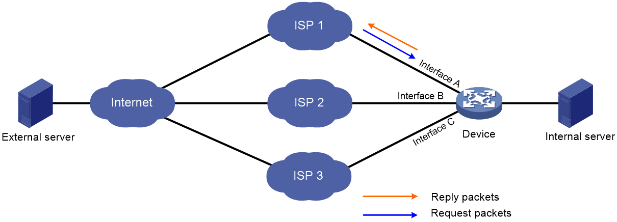
As is shown in Figure 1, when the external server sends a request to the internal server, the packet travels through ISP 1 to Interface A on the device. The last hop holding feature on the device ensures that the reply packet follows the same route as the request packet back to ISP 1. If last hop holding is disabled, the reply packet might be sent out of Interface B or Interface C to the external network.
Figure 1 Last hop holding application
Restrictions and guidelines
On a device supporting fast forwarding, the device creates fast forwarding entries based on the flow information and last hop information. In this case, last hop holding is based on fast forwarding entries. If the MAC address of a last hop changes on an Ethernet link, this feature can function correctly only after the fast forwarding entry is updated for the MAC address.
This feature is not applicable to an MPLS network.
Procedure
1. Enter system view.
system-view
2. Enter Layer 3 Ethernet interface view or subinterface view.
interface interface-type { interface-number | interface-number.subnumber }
3. Enable last hop holding.
ip last-hop hold
By default, last hop holding is disabled.
Enabling consistency check for IPv4 FIB entries
About this task
This feature enables the device to perform consistency check regularly on all the IPv4 FIB entries in the software and hardware. If the device detects any inconsistency, it updates entries in hardware based on entries in the software.
Procedure
1. Enter system view.
system-view
2. Enable consistency check for IPv4 FIB entries.
ip fib consistency-check enable
By default, consistency check for IPv4 FIB entries is disabled.
Configuring HPF maintenance features
Configuring trace information recording for an ingress node
About this task
In HPF mode, the trace entry generated for a packet records the nodes that process the packet, including the ingress node. To locate packet forwarding issues, such as packet forwarding failures, use the display hpf trace command and analyze the displayed HPF trace information.
This feature enables the device to generate trace entries for packets processed by an ingress node. When an ingress node processes a packet, the device generates one trace entry for that packet.
When the device records a large amount of trace entries, you can configure specific trace information filters for selective trace information display. For example, to view the trace information generated for packets with a specific IPv4 destination address, you can configure an ACL as the HPF trace information filter for the IPv4 module.
Procedure
Executing the following commands in user view:
1. Enable trace information recording for an ingress node.
hpf trace add { node-name node-name | node-index node-index } max-record-count max-record-number [ total-filter-count total-filter-number ] slot slot-number
By default, trace information recording are disabled for an ingress node.
When you configure this command, follow these restrictions and guidelines:
¡ If you specify a total-filter-number value, each HPF thread will filter out up to max-record-number trace entries from the latest total-filter-number trace entries.
¡ If you do not specify a total-filter-number value, each HPF thread will filter out up to max-record-number trace entries from all recorded trace entries.
¡ If you execute this command for the same ingress node multiple times, the effective max-record-number value is the sum of all specified max-record-number values.
¡ When the total max-record-number value configured for a thread has reached 1000, the display hpf trace command cannot display the subsequent trace entries of that thread. To resolve this issue, use the clear hpf trace command to clear all HPF trace information, reconfigure the hpf trace add command, and then use the display hpf trace command again.
2. (Optional.) Configure a node as a trace information filter.
hpf trace filter { exclude | include } { node-name node-name | node-index node-index } max-count count-num slot slot-number
By default, no node is configured as a trace information filter.
3. (Optional.) Configure an HPF trace information filter for the Ethernet module.
hpf trace filter ethernet { acl { [ ipv6 ] { advanced-acl-number | basic-acl-number } | mac mac-acl-number } | interface interface-type interface-number } slot slot-number
By default, no HPF trace information filter is configured for the Ethernet module.
4. (Optional.) Configure an HPF trace information filter for the IP module.
hpf trace filter ip acl acl-number slot slot-number
By default, no HPF trace information filter is configured for the IP module.
5. (Optional.) Configure an HPF trace information filter for the IPv6 module.
hpf trace filter ipv6 acl acl-number slot slot-number
By default, no HPF trace information filter is configured for the IPv6 module.
6. (Optional.) Configure an HPF trace information filter for the TCP module.
hpf trace filter tcp { acl acl-number | acl6 ipv6-acl-number }
slot slot-number
By default, no HPF trace information filter is configured for the TCP module.
7. (Optional.) Configure an HPF trace information filter for the UDP module.
hpf trace filter udp { acl acl-number | acl6 ipv6-acl-number } slot slot-number
By default, no HPF trace information filter is configured for the UDP module.
8. (Optional.) Clear the running data of all HPF threads.
hpf thread clear slot slot-number
Enabling trace information recording for a frame queue
About this task
In HPF mode, a thread might transmit packets to another thread for processing. For example, to reassemble an IPv4 packet, all of its fragments must be transmitted to the same thread for packet reassembly. When a service module implements cross-thread packet processing, it creates frame queues for temporary packet storage.
To view trace information of a frame queue when the service module associated with that frame queue implements cross-thread packet processing, perform the following task:
1. Use the hpf frame-queue trace enable command to enable trace information recording for the frame queue.
2. Use the display system internal hpf frame-queue trace command to display trace information of the frame queue.
3. Use the display system internal hpf frame-queue histogram trace command to view the frequency of cross-thread packet processing.
Procedure
To enable trace information recording for a frame queue, use the following command in user view:
hpf frame-queue-trace { name name | index index } enable slot slot-number
By default, trace information recording are disabled for frame queues.
Displaying memory usage information for service modules that rely on HPF
Perform the folllowing tasks in any view:
· Display heap memory statistics for service modules that rely on HPF.
display hpf memory heap [ tag tag-id ] [ size block-size | verbose ] [ slot slot-number [ cpu cpu-number ] ]
display hpf memory heap tag [ slot slot-number [ cpu cpu-number ] ]
· Display pool memory statistics for service modules that rely on HPF.
display hpf memory pool [ slot slot-number [ cpu cpu-number ] ] [ pool-name name ]
Enabling IPv4 packet forwarding on an interface with no IPv4 address configured
About this task
On a device that supports both IPv4 and IPv6, the next hop of an IPv4 packet might be an IPv4 address or an IPv6 address. If the output interface has no IPv4 address configured, the interface cannot forward the IPv4 packet. To solve this problem, enable this feature on the interface. This feature allows the interface to forward IPv4 packets even though the interface has no IPv4 address configured.
Restrictions and guidelines
You can configure this feature in any view in which an IPv4 address can be configured.
Procedure
1. Enter system view.
system-view
2. Enter interface view.
interface interface-type interface-number
3. Enable IPv4 packet forwarding on an interface that has no IPv4 address configured.
ip forwarding
By default, IPv4 packet forwarding is disabled on an interface that has no IPv4 address configured.
Enabling SNMP notifications for FIB events
About this task
This feature enables the FIB module to generate SNMP notifications for critical FIB events, such as the exceeding of the message queue length threshold. The SNMP notifications are sent to the SNMP module. For the SNMP notifications to be sent correctly, you must also configure SNMP. For more information about SNMP configuration, see Network Management and Monitoring Configuration Guide.
Procedure
1. Enter system view.
system-view
2. Enable SNMP notifications for FIB events.
snmp-agent trap enable fib
By default, SNMP notifications for FIB events are enabled.
Display and maintenance commands for IP forwarding basics
Display and maintenance commands for FIB table
· To display FIB entries, execute the following command in any view:
display fib [ vpn-instance vpn-instance-name ] [ ip-address [ mask | mask-length ] ] [ slot slot-number ]
· To display HPF trace information, use the following command in user view:
Displaying the differences in FIB entries between two slots
· To display the differences in FIB entries between two slots, execute the following command in any view:
display fib prefix diff [ all | [ vpn-instance vpn-instance-name ] [ ip-address [ mask | mask-length ] ] ] slot slot-number1 slot slot-number2
· To display the differences in FIB VN entries between two slots, execute the following command in any view:
display fib vn diff [ id id ] slot slot-number1 slot slot-number2