- Table of Contents
-
- 07-Layer 3—IP Services Configuration Guide
- 00-Preface
- 01-ARP configuration
- 02-IP addressing configuration
- 03-DHCP configuration
- 04-DNS configuration
- 05-NAT configuration
- 06-NAT66 configuration
- 07-IP forwarding basics configuration
- 08-Fast forwarding configuration
- 09-Multi-CPU packet distribution configuration
- 10-Adjacency table configuration
- 11-IRDP configuration
- 12-IP performance optimization configuration
- 13-UDP helper configuration
- 14-IPv6 basics configuration
- 15-DHCPv6 configuration
- 16-IPv6 fast forwarding configuration
- 17-AFT configuration
- 18-Tunneling configuration
- 19-GRE configuration
- 20-ADVPN configuration
- 21-WAAS configuration
- 22-Lighttpd service configuration
- 23-Web caching configuration
- 24-STUN configuration
- Related Documents
-
| Title | Size | Download |
|---|---|---|
| 17-AFT configuration | 394.82 KB |
Content
Static port block mapping-based IPv6-to-IPv4 source address translation
Restrictions: Hardware compatibility with AFT
Configuring an IPv6-to-IPv4 destination address translation policy
About IPv6-to-IPv4 destination address translation policies
Configuring an AFT mapping for an IPv4 internal server
Configuring an IPv4-to-IPv6 source address static mapping
Configuring IPv6-to-IPv4 source address translation settings
About IPv6-to-IPv4 source address translation settings
Configuring an IPv6-to-IPv4 source address static mapping
Configuring an IPv6-to-IPv4 source address dynamic translation policy
Configuring a port block group-based IPv6-to-IPv4 source address static translation policy
Configuring an IPv4-to-IPv6 destination address translation policy
About IPv4-to-IPv6 destination address translation policies
Configuring an AFT mapping for an IPv6 internal server
Configuring an IPv6-to-IPv4 source address static mapping
Configuring an IPv4-to-IPv6 destination address translation policy based on IVI or general prefix
Configuring an IPv4-to-IPv6 source address translation policy
About IPv4-to-IPv6 source address translation policies
Configuring an IPv4-to-IPv6 source address static mapping
Configuring an IPv4-to-IPv6 source address translation policy based on NAT64 or general prefix
Setting the ToS field to 0 for translated IPv4 packets
Setting the Traffic Class field to 0 for translated IPv6 packets
Configuring AFT high availability
Enabling AFT port halving for IRF hot backup
Associating an AFT address group with a VRRP group
Enable dynamic port block mapping synchronization
Configuring threshold violation logging
Display and maintenance commands for AFT
Example: Allowing IPv4 Internet access from an IPv6 network
Example: Providing FTP service from an IPv6 network to the IPv4 Internet
Example: Allowing mutual access between IPv4 and IPv6 networks
Example: Allowing IPv6 Internet access from an IPv4 network
Example: Providing FTP service from an IPv4 network to the IPv6 Internet
Configuring AFT
About AFT
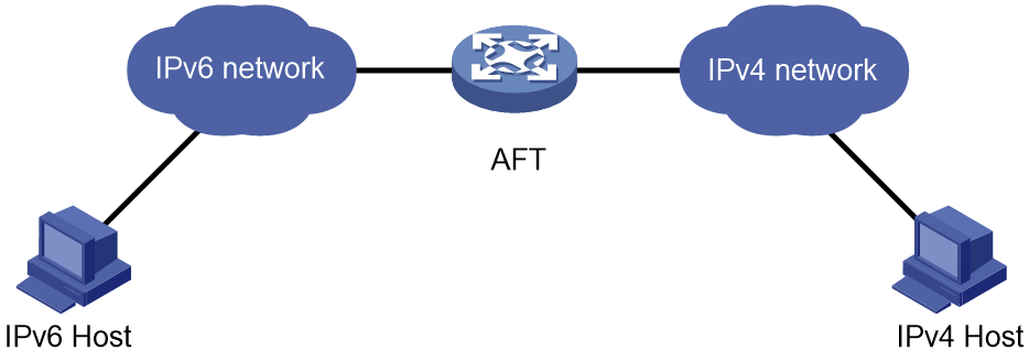
Address Family Translation (AFT) translates an IP address of one address family into an IP address of the other address family. It enables an IPv4 network and an IPv6 network to communicate with each other, as shown in Figure 1. The IPv4 host and the IPv6 host can communicate with each other without changing the existing configuration.
Figure 1 AFT application scenario
AFT translation methods
Static AFT
Static AFT creates a fixed mapping between an IPv4 address and an IPv6 address.
To perform static AFT, you can configure IPv4-to-IPv6 source address static translation policies and IPv6-to-IPv4 source address static translation policies.
An IPv4-to-IPv6 source address static translation policy can be applied to the following scenarios:
· For an IPv4-initiated session packet, if the source IPv4 address in the packet matches the translation policy, AFT translates the source IPv4 address in the packet to the specified IPv6 address.
· For an IPv6-initiated session packet, if the destination IPv6 address in the packet matches the translation policy, AFT translates the destination IPv6 address in the packet to the specified IPv4 address.
An IPv6-to-IPv4 source address static translation policy can be applied to the following scenarios:
· For an IPv6-initiated session packet, if the source IPv6 address in the packet matches the translation policy, AFT translates the source IPv6 address in the packet to the specified IPv4 address.
· For an IPv4-initiated session packet, if the destination IPv4 address in the packet matches the translation policy, AFT translates the destination IPv4 address in the packet to the specified IPv6 address.
Dynamic AFT
Dynamic AFT creates a dynamic mapping between an IPv4 address and an IPv6 address.
When dynamic AFT performs IPv6-to-IPv4 source address translation, the Not Port Address Translation (NO-PAT) and Port Address Translation (PAT) modes are available.
NO-PAT
NO-PAT translates one IPv6 address to one IPv4 address. An IPv4 address assigned to one IPv6 host cannot be used by any other IPv6 host until it is released.
NO-PAT supports all IP packets.
PAT
PAT translates multiple IPv6 addresses to a single IPv4 address by mapping each IPv6 address and port to the IPv4 address and a unique port. PAT supports the following packet types:
· TCP packets.
· UDP packets.
· ICMPv6 echo request and echo reply messages.
PAT supports port blocks for connection limit and user tracing. Port blocks are generated by dividing the port range (1024 to 65535) by the port block size. Port block based PAT maps multiple IPv6 addresses to one IPv4 address and uses a port block for each IPv6 address.
Port block based PAT functions as follows:
1. When an IPv6 host first initiates a connection to the IPv4 network, it creates a mapping from the host's IPv6 address to an IPv4 address and a port block.
2. It translates the IPv6 address to the IPv4 address, and the source ports to ports in the port block for subsequent connections from the IPv6 host until the ports in the port block are exhausted.
|
|
NOTE: If the port range cannot be divided by the port block size exactly, the remaining ports are not used for translation. |
Prefix translation
NAT64 prefix translation
NAT64 prefix is an IPv6 address prefix used to construct an IPv6 address representing an IPv4 node in an IPv6 network. The IPv6 hosts do not use a constructed IPv6 address as their real IP address. The length of a NAT64 prefix can be 32, 40, 48, 56, 64, or 96.
As shown in Figure 2, the construction methods vary depending on the NAT64 prefix length. Bits 64 through 71 in the constructed IPv6 address are reserved bits, which must be set to 0.
· If the prefix length is 32, 64, or 96 bits, the IPv4 address contained in the IPv6 address will be intact.
· If the prefix length is 40, 48, or 56 bits, the IPv4 address contained in the IPv6 address will be divided into two parts by bits 64 through 71.
Figure 2 IPv6 address construction with NAT 64 prefix and IPv4 address
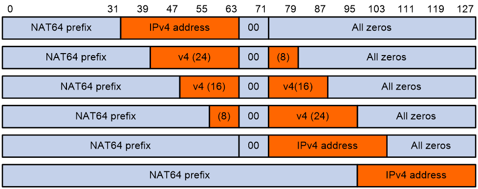
Table 1 Examples of IPv6 address construction with NAT64 prefix and IPv4 address
|
IPv6 prefix |
IPv4 address |
Constructed IPv6 address |
|
2001:db8::/32 |
192.0.2.33 |
2001:db8:c000:221:: |
|
2001:db8:100::/40 |
192.0.2.33 |
2001:db8:1c0:2:21:: |
|
2001:db8:122::/48 |
192.0.2.33 |
2001:db8:122:c000:2:2100:: |
|
2001:db8:122:300::/56 |
192.0.2.33 |
2001:db8:122:3c0:0:221:: |
|
2001:db8:122:344::/64 |
192.0.2.33 |
2001:db8:122:344:c0:2:2100:: |
|
2001:db8:122:344::/96 |
192.0.2.33 |
2001:db8:122:344::192.0.2.33 |
AFT uses a NAT64 prefix to perform the following translation:
· IPv4-to-IPv6 source address translation. AFT translates a source IPv4 address to an IPv6 address that is created by using the NAT64 prefix and the IPv4 address.
· IPv6-to-IPv4 destination address translation. AFT uses the NAT64 prefix to match destination IPv6 addresses and extracts the embedded IPv4 address from the matching IPv6 addresses.
A NAT64 prefix cannot be on the same subnet as any interface on the device.
IVI prefix translation
An IVI prefix is a 32-bit IPv6 address prefix. An IVI address is the IPv6 address that an IPv6 node uses. As shown in Figure 3, the IVI address includes an IVI prefix and an IPv4 address.
![]()
AFT uses an IVI prefix for IPv6-to-IPv4 source address translation. If a source IPv6 address matches the IVI prefix, AFT translates it to the embedded IPv4 address.
General prefix translation
A general prefix is an IPv6 address prefix used to construct an IPv6 address representing an IPv4 node in an IPv6 network. The length of a general prefix can be 32, 40, 48, 56, 64, or 96.
As shown in Figure 4, a general prefix based IPv6 address does not have bits 64 through 71 reserved as a NAT64 prefix based IPv6 address does. An IPv4 address is embedded as a whole into an IPv6 address.
Figure 4 General prefix based IPv6 address format

AFT uses a general prefix for IPv6-to-IPv4 source and destination address translation. If a source or destination IPv6 address matches the general prefix, AFT translates it to the embedded IPv4 address.
A general prefix cannot be on the same subnet as any interface on the device.
IPv6 internal server
IPv6 internal server maps the IPv6 address and port number of an IPv6 internal server to an IPv4 address and port number. It allows the IPv6 internal server to provide services to IPv4 hosts.
IPv4 internal server
IPv4 internal server maps the IPv4 address and port number of an IPv4 internal server to an IPv6 address and port number. It allows the IPv4 internal server to provide services to IPv6 hosts.
Static port block mapping-based IPv6-to-IPv4 source address translation
AFT algorithmically creates static port block mappings based on the port block group configuration in a port block group-based IPv6-to-IPv4 source address static translation policy. A static port block mapping maps an IPv6 prefix to a unique IPv4 address and port block pair. When an IPv6-initiated session packet matches an IPv6 prefix in the policy, AFT translates the source IPv6 address of the packet into the IPv4 address and a TCP or UDP port number in the port block of the matching entry.
AFT translation process
The address translation differs for IPv6-initiated communication and IPv4-initiated communication.
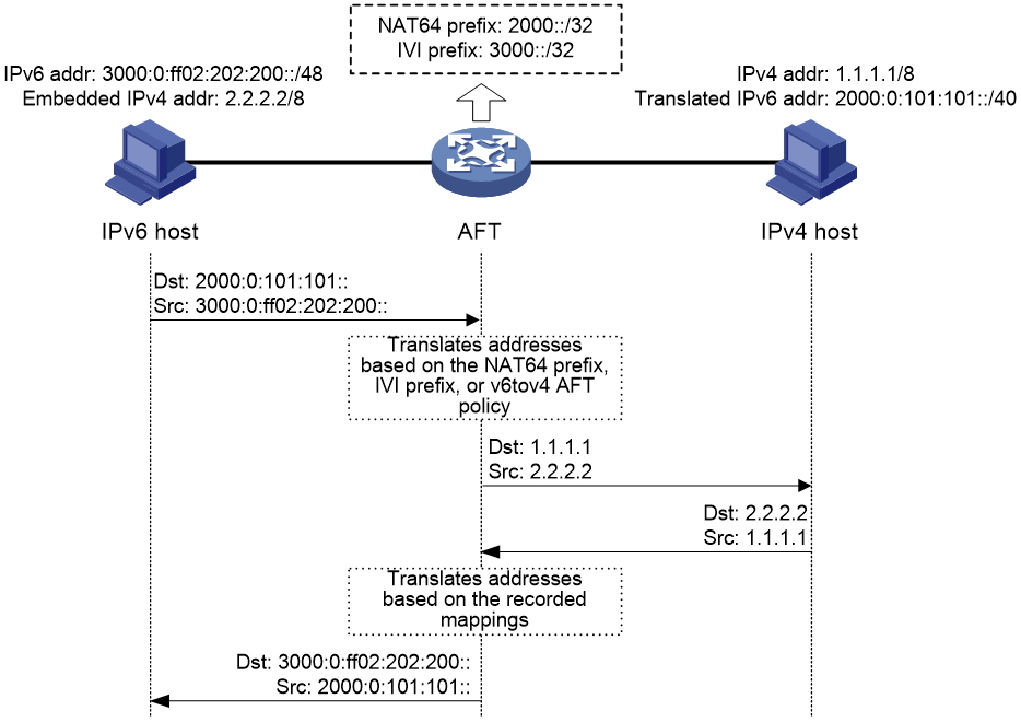
IPv6-initiated communication
As shown in Figure 5, when the IPv6 host initiates access to the IPv4 host, AFT operates as follows:
1. Upon receiving a packet from the IPv6 host, AFT compares the packet with IPv6-to-IPv4 destination address translation policies.
¡ If a matching policy is found, AFT translates the destination IPv6 address according to the policy.
¡ If no matching policy is found, AFT does not process the packet.
2. AFT performs pre-lookup to determine the output interface for the translated packet. PBR is not used for the pre-lookup.
¡ If a matching route is found, the process goes to step 3.
¡ If no matching route is found, AFT discards the packet.
3. AFT compares the source IPv6 address of the packet with IPv6-to-IPv4 source address translation policies.
¡ If a matching policy is found, AFT translates the source IPv6 address according to the policy.
¡ If no matching policy is found, AFT discards the packet.
4. AFT forwards the translated packet and records the mappings between IPv6 addresses and IPv4 addresses.
5. AFT translates the IPv4 addresses in the response packet header to IPv6 addresses based on the address mappings before packet forwarding.
For more information about IPv6-to-IPv4 destination address translation policies, see "Configuring an IPv6-to-IPv4 destination address translation policy."
For more information about IPv6-to-IPv4 source address translation policies, see "Configuring IPv6-to-IPv4 source address translation settings."
Figure 5 AFT process for IPv6-initiated communication
IPv4-initiated communication
As shown in Figure 6, when the IPv4 host initiates access to the IPv6 host, AFT operates as follows:
1. Upon receiving a packet from the IPv4 host, AFT compares the packet with IPv4-to-IPv6 destination address translation policies.
¡ If a matching policy is found, AFT translates the destination IPv4 address according to the policy.
¡ If no matching policy is found, AFT does not perform address translation.
2. AFT performs the pre-lookup to determine output interface for the translated packet. PBR is not used for the pre-lookup.
¡ If a matching route is found, the process goes to step 3.
¡ If no matching route is found, AFT discards the packet.
3. AFT compares the source IPv4 address with IPv4-to-IPv6 source address translation policies.
¡ If a matching policy is found, AFT translates the source IPv4 address according to the policy.
¡ If no matching policy is found, AFT discards the packet.
4. AFT forwards the translated packet and records the mappings between IPv4 addresses and IPv6 addresses.
5. AFT translates the IPv6 addresses in the response packet header to IPv4 addresses based on the address mappings before packet forwarding.
For more information about IPv4-to-IPv6 destination address translation policies, see "Configuring an IPv4-to-IPv6 destination address translation policy."
For more information about IPv4-to-IPv6 source address translation policies, see "Configuring an IPv4-to-IPv6 source address translation policy."
Figure 6 AFT process for IPv4-initiated communication

AFT ALG
AFT ALG translates address or port information in the application layer payloads.
For example, an FTP application includes a data connection and a control connection. The IP address and port number for the data connection depend on the payload information of the control connection. This requires AFT ALG to translate the address and port information.
Restrictions and guidelines
An AFTed packet will not be NATed.
Restrictions: Hardware compatibility with AFT
|
Hardware |
AFT compatibility |
|
MSR610 |
Yes |
|
MSR810, MSR810-W, MSR810-W-DB, MSR810-LM, MSR810-W-LM, MSR810-10-PoE, MSR810-LM-HK, MSR810-W-LM-HK, MSR810-LM-CNDE-SJK, MSR810-CNDE-SJK, MSR810-EI, MSR810-LM-EA, MSR810-LM-EI |
Yes |
|
MSR810-LMS, MSR810-LUS |
No |
|
MSR810-SI, MSR810-LM-SI |
No |
|
MSR810-LMS-EA, MSR810-LME |
Yes |
|
MSR1004S-5G, MSR1004S-5G-CN |
Yes |
|
MSR1104S-W, MSR1104S-W-CAT6, MSR1104S-5G-CN, MSR1104S-W-5G-CN |
Yes |
|
MSR2600-6-X1, MSR2600-15-X1, MSR2600-15-X1-T |
Yes |
|
MSR2600-10-X1 |
Yes |
|
MSR 2630 |
Yes |
|
MSR3600-28, MSR3600-51 |
Yes |
|
MSR3600-28-SI, MSR3600-51-SI |
Yes |
|
MSR3600-28-X1, MSR3600-28-X1-DP, MSR3600-51-X1, MSR3600-51-X1-DP |
Yes |
|
MSR3600-28-G-DP, MSR3600-51-G-DP |
Yes |
|
MSR3610-I-DP, MSR3610-IE-DP, MSR3610-IE-ES, MSR3610-IE-EAD, MSR-EAD-AK770, MSR3610-I-IG, MSR3610-IE-IG |
Yes |
|
MSR3610-X1, MSR3610-X1-DP, MSR3610-X1-DC, MSR3610-X1-DP-DC, MSR3620-X1, MSR3640-X1 |
Yes |
|
MSR 3610, MSR 3620, MSR 3620-DP, MSR 3640, MSR 3660 |
Yes |
|
MSR3610-G, MSR3620-G |
Yes |
|
MSR3640-G |
Yes |
|
MSR3640-X1-HI |
Yes |
|
Hardware |
AFT compatibility |
|
MSR810-W-WiNet, MSR810-LM-WiNet |
Yes |
|
MSR830-4LM-WiNet |
Yes |
|
MSR830-5BEI-WiNet, MSR830-6EI-WiNet, MSR830-10BEI-WiNet |
Yes |
|
MSR830-6BHI-WiNet, MSR830-10BHI-WiNet |
Yes |
|
MSR2600-6-WiNet |
Yes |
|
MSR2600-10-X1-WiNet |
Yes |
|
MSR2630-WiNet |
Yes |
|
MSR3600-28-WiNet |
Yes |
|
MSR3610-X1-WiNet |
Yes |
|
MSR3610-WiNet, MSR3620-10-WiNet, MSR3620-DP-WiNet, MSR3620-WiNet, MSR3660-WiNet |
Yes |
|
Hardware |
AFT compatibility |
|
MSR860-6EI-XS |
Yes |
|
MSR860-6HI-XS |
Yes |
|
MSR2630-XS |
Yes |
|
MSR3600-28-XS |
Yes |
|
MSR3610-XS |
Yes |
|
MSR3620-XS |
Yes |
|
MSR3610-I-XS |
Yes |
|
MSR3610-IE-XS |
Yes |
|
MSR3620-X1-XS |
Yes |
|
MSR3640-XS |
Yes |
|
MSR3660-XS |
Yes |
|
Hardware |
AFT compatibility |
|
MSR810-LM-GL |
Yes |
|
MSR810-W-LM-GL |
Yes |
|
MSR830-6EI-GL |
Yes |
|
MSR830-10EI-GL |
Yes |
|
MSR830-6HI-GL |
Yes |
|
MSR830-10HI-GL |
Yes |
|
MSR1004S-5G-GL |
Yes |
|
MSR2600-6-X1-GL |
Yes |
|
MSR3600-28-SI-GL |
Yes |
AFT tasks at a glance
To configure AFT, perform the following tasks:
1. Enabling AFT
2. Configuring address translation for IPv6-initiated communication
You can perform the following tasks or configure global NAT policies to configure address translation for IPv6-initiated communication. For more information about global NAT policies, see "Configuring NAT."
¡ Configuring an IPv6-to-IPv4 destination address translation policy
¡ Configuring IPv6-to-IPv4 source address translation settings
¡ (Optional.) Setting the ToS field to 0 for translated IPv4 packets
3. Configuring address translation for IPv4-initiated communication
You can perform the following tasks or configure global NAT policies to configure address translation for IPv4-initiated communication. For more information about global NAT policies, see "Configuring NAT."
¡ Configuring an IPv4-to-IPv6 destination address translation policy
¡ Configuring an IPv4-to-IPv6 source address translation policy
¡ (Optional.) Setting the Traffic Class field to 0 for translated IPv6 packets
4. (Optional.) Configuring AFT ALG
5. (Optional.) Configuring AFT high availability
¡ Enabling AFT port halving for IRF hot backup
¡ Associating an AFT address group with a VRRP group
¡ Enable dynamic port block mapping synchronization
6. (Optional.) Enabling AFT logging
¡ Configuring threshold violation logging
Enabling AFT
Restrictions and guidelines
To implement address translation between IPv4 and IPv6 networks, you must enable AFT on interfaces connected to the IPv4 network and interfaces connected to the IPv6 network.
Procedure
1. Enter system view.
system-view
2. Enter interface view.
interface interface-type interface-number
3. Enable AFT.
aft enable
By default, AFT is disabled.
Configuring an IPv6-to-IPv4 destination address translation policy
About IPv6-to-IPv4 destination address translation policies
AFT compares an IPv6 packet with IPv6-to-IPv4 destination address translation policies in the following order:
1. AFT mappings for IPv4 internal servers.
2. IPv4-to-IPv6 source address static mappings.
3. General prefixes.
4. NAT64 prefixes.
Configuring an AFT mapping for an IPv4 internal server
1. Enter system view.
system-view
2. Configure an AFT mapping for an IPv4 internal server.
aft v4server protocol protocol-type ipv6-destination-address ipv6-port-number [ vpn-instance ipv6-vpn-instance-name ] ipv4-destination-address ipv4-port-number [ vpn-instance ipv4-vpn-instance-name ] [ vrrp virtual-router-id ]
By default, no AFT mapping for an IPv4 internal server is configured.
Configuring an IPv4-to-IPv6 source address static mapping
Restrictions and guidelines
An IPv4-to-IPv6 source address static translation policy creates a one-to-one mapping between an IPv4 address and an IPv6 address, and can be applied to the following scenarios:
· For an IPv4-initiated session packet, if the source IPv4 address in the packet matches the translation policy, AFT translates the source IPv4 address in the packet to the specified IPv6 address.
· For an IPv6-initiated session packet, if the destination IPv6 address in the packet matches the translation policy, AFT translates the destination IPv6 address in the packet to the specified IPv4 address.
Procedure
1. Enter system view.
system-view
2. Configure an IPv4-to-IPv6 source address static mapping.
aft v4tov6 source ipv4-address [ vpn-instance ipv4-vpn-instance-name ] ipv6-address [ vpn-instance ipv6-vpn-instance-name ] [ vrrp virtual-router-id ]
By default, no IPv4-to-IPv6 source address static mapping is configured.
Configuring a general prefix
1. Enter system view.
system-view
2. Configure a general prefix.
aft prefix-general prefix-general prefix-length
By default, no general prefix is configured.
Configuring a NAT64 prefix
1. Enter system view.
system-view
2. Configure a NAT64 prefix.
aft prefix-nat64 prefix-nat64 prefix-length
By default, no NAT64 prefix is configured.
Configuring IPv6-to-IPv4 source address translation settings
About IPv6-to-IPv4 source address translation settings
AFT compares an IPv6 packet with IPv6-to-IPv4 source address translation settings in the following order:
1. IPv6-to-IPv4 source address static mappings.
2. General prefixes.
3. IVI prefixes.
4. Port block group-based IPv6-to-IPv4 source address static translation policies.
5. IPv6-to-IPv4 source address dynamic translation policies.
Configuring an IPv6-to-IPv4 source address static mapping
Restrictions and guidelines
An IPv6-to-IPv4 source address static translation policy creates a one-to-one mapping between an IPv6 address and an IPv4 address, and can be applied to the following scenarios:
· For an IPv6-initiated session packet, if the source IPv6 address in the packet matches the translation policy, AFT translates the source IPv6 address in the packet to the specified IPv4 address.
· For an IPv4-initiated session packet, if the destination IPv4 address in the packet matches the translation policy, AFT translates the destination IPv4 address in the packet to the specified IPv6 address.
Procedure
1. Enter system view.
system-view
2. Configure an IPv6-to-IPv4 source address static mapping.
aft v6tov4 source ipv6-address [ vpn-instance ipv6-vpn-instance-name ] ipv4-address [ vpn-instance ipv4-vpn-instance-name ] [ vrrp virtual-router-id ]
Configuring a general prefix
1. Enter system view.
system-view
2. Configure a general prefix.
aft prefix-general prefix-general prefix-length
Configuring an IVI prefix
1. Enter system view.
system-view
2. Configure an IVI prefix for IPv6-to-IPv4 source address translation.
aft prefix-ivi prefix-ivi
Configuring an IPv6-to-IPv4 source address dynamic translation policy
About this task
An IPv6-to-IPv4 source address dynamic translation policy uses dynamic IPv6-to-IPv4 mappings for IPv6-to-IPv4 source address translation. In PAT mode, AFT translates multiple IPv6 addresses to a single IPv4 address by mapping each IPv6 address and port to the IPv4 address and a unique port. PAT supports the following packet types:
· TCP packets.
· UDP packets.
· ICMPv6 echo request and echo reply messages.
Procedure
1. Enter system view.
system-view
2. (Optional.) Configure an AFT address group.
a. Create an AFT address group and enter AFT address group view.
aft address-group group-id
This step is required if you decide to use an address group in an IPv6-to-IPv4 source address dynamic translation policy.
b. Add an address range to the address group.
address start-address end-address
You can add multiple address ranges to an address group, but the address ranges must not overlap.
c. Return to system view.
quit
This configuration is supported only for the IPv6-to-IPv4 source address dynamic translation policies.
3. Configure an IPv6-to-IPv4 source address dynamic translation policy.
aft v6tov4 source { acl ipv6 { name ipv6-acl-name | number ipv6-acl-number } | prefix-nat64 prefix-nat64 prefix-length [ vpn-instance ipv6--vpn-instance-name ] } { address-group group-id [ no-pat | port-block-size blocksize [ extended-block-number extended-block-number ] [ port-range start-port-number end-port-number ] ] | interface interface-type interface-number } [ vpn-instance ipv4-vpn-instance-name ]
Configuring a port block group-based IPv6-to-IPv4 source address static translation policy
About this task
To create a port block group-based IPv6-to-IPv4 source address static translation policy, you must create a port block group for the policy first. A port block group contains the following settings:
· Address ranges:
¡ IPv4 address ranges used for IPv6-to-IPv4 source address static translation.
¡ IPv6 prefix ranges used to match the IPv6 addresses to be translated.
· Port range, which will be divided into port blocks of the user-defined port block size. Each port block is paired with an IPv4 address to match an IPv6 prefix for IPv6-to-IPv4 source address translation.
· Port block size.
After the policy is created, the device algorithmically maps each IPv6 prefix to a unique IPv4 address and port block pair according to the policy's port block group configuration. If not enough unique IPv4 address and port block pairs are available, excessive IPv6 prefixes will be ignored and IPv6 addresses matching those IPv6 prefixes cannot be translated.
The total number of IPv6 prefixes that can be mapped equals to the total number of unique IPv4 address and port block pairs in the policy, which is calculated as follows:
Total number of IPv6 prefixes that can be mapped = N × M, where:
· N is the total number of port blocks in the port block group, which is result of dividing the port range by the port block size.
· M is the total number of IPv4 addresses in the policy available for IPv6-to-IPv4 translation.
For example, assuming that a policy contains two IPv4 addresses (x1 and y1) and n port blocks. The device takes n IPv6 prefixes in the port block group, maps them to the same IPv4 address paired in turn with the first to nth port blocks. The created static port block mappings are as follows:
· IPv6 prefix x1<-->IPv4 address X1 + Port block 1
· IPv6 prefix x2<-->IPv4 address X1 + Port block 2
· …
· IPv6 prefix xn<-->IPv4 address X1 + Port block n
· IPv6 prefix y1<-->IPv4 address Y1 + Port block 1
· IPv6 prefix y2<-->IPv4 address Y1 + Port block 2
· …
· IPv6 prefix yn<-->IPv4 address Y1 + Port block n.
Procedure
1. Enter system view.
system-view
2. Create an AFT port block group and enter its view.
aft port-block-group block-group-id
3. Add an IPv6 prefix range to the port block group.
ipv6-prefix ipv6-start-prefix ipv6-end-prefix prefix-length [ vpn-instance vpn-name ]
By default, an AFT port block group does not contain any IPv6 prefix ranges.
4. Add an IPv4 address range to the port block group.
ip-address start-address end-address [ vpn-instance vpn-name ]
By default, an AFT port block group does not contain any IPv4 address ranges.
5. Specify the port range for the port block group.
port-range start-port-number end-port-number
By default, an AFT port block group uses port range 1 to 65535.
6. Set the port block size for the port block group.
block-size block-size-value
The default port block size is 256.
7. Return to system view.
quit
8. Create an IPv6-to-IPv4 source address static translation policy based on the port block group.
aft v6tov4 source port-block-group group-id
By default, no port block group-based IPv6-to-IPv4 source address static translation policies exist.
Configuring an IPv4-to-IPv6 destination address translation policy
About IPv4-to-IPv6 destination address translation policies
AFT compares an IPv4 packet with IPv4-to-IPv6 destination address translation policies in the following order:
1. AFT mappings for IPv6 internal servers.
2. IPv6-to-IPv4 source address static mappings.
3. IPv4-to-IPv6 destination address translation policies that use IVI prefixes or general prefixes.
Configuring an AFT mapping for an IPv6 internal server
1. Enter system view.
system-view
2. Configure an AFT mapping for an IPv6 internal server.
aft v6server protocol protocol-type ipv4-destination-address ipv4-port-number [ vpn-instance ipv4-vpn-instance-name ] ipv6-destination-address ipv6-port-number [ vpn-instance ipv6-vpn-instance-name ] [ vrrp virtual-router-id ]
Configuring an IPv6-to-IPv4 source address static mapping
Restrictions and guidelines
An IPv6-to-IPv4 source address static translation policy creates a one-to-one mapping between an IPv6 address and an IPv4 address, and can be applied to the following scenarios:
· For an IPv6-initiated session packet, if the source IPv6 address in the packet matches the translation policy, AFT translates the source IPv6 address in the packet to the specified IPv4 address.
· For an IPv4-initiated session packet, if the destination IPv4 address in the packet matches the translation policy, AFT translates the destination IPv4 address in the packet to the specified IPv6 address.
Procedure
1. Enter system view.
system-view
2. Configure an IPv6-to-IPv4 source address static mapping.
aft v6tov4 source ipv6-address [ vpn-instance ipv6-vpn-instance-name ] ipv4-address [ vpn-instance ipv4-vpn-instance-name ] [ vrrp virtual-router-id ]
Configuring an IPv4-to-IPv6 destination address translation policy based on IVI or general prefix
1. Enter system view.
system-view
2. Configure an IVI prefix or general prefix. Choose one option as needed:
¡ Configure an IVI prefix.
aft prefix-ivi prefix-ivi
¡ Configure a general prefix.
aft prefix-general prefix-general prefix-length
3. Configure an IPv4-to-IPv6 destination address translation policy that uses an IVI prefix or a general prefix.
aft v4tov6 destination acl { name ipv4-acl-name prefix-ivi prefix-ivi [ vpn-instance ipv6-vpn-instance-name ] | number ipv4-acl-number { prefix-general prefix-general prefix-length | prefix-ivi prefix-ivi [ vpn-instance ipv6-vpn-instance-name ] } }
You can use a nonexistent IVI prefix or general prefix in a policy, but the policy takes effect only after you configure the prefix.
Configuring an IPv4-to-IPv6 source address translation policy
About IPv4-to-IPv6 source address translation policies
AFT compares an IPv4 packet with IPv4-to-IPv6 source address translation policies in the following order:
1. IPv4-to-IPv6 source address static mappings.
2. IPv4-to-IPv6 source address translation policies that use NAT64 prefixes or general prefixes.
3. The first NAT64 prefix.
Configuring an IPv4-to-IPv6 source address static mapping
Restrictions and guidelines
An IPv4-to-IPv6 source address static translation policy creates a one-to-one mapping between an IPv4 address and an IPv6 address, and can be applied to the following scenarios:
· For an IPv4-initiated session packet, if the source IPv4 address in the packet matches the translation policy, AFT translates the source IPv4 address in the packet to the specified IPv6 address.
· For an IPv6-initiated session packet, if the destination IPv6 address in the packet matches the translation policy, AFT translates the destination IPv6 address in the packet to the specified IPv4 address.
Procedure
1. Enter system view.
system-view
2. Configure an IPv4-to-IPv6 source address static mapping.
aft v4tov6 source ipv4-address [ vpn-instance ipv4-vpn-instance-name ] ipv6-address [ vpn-instance ipv6-vpn-instance-name ] [ vrrp virtual-router-id ]
Configuring an IPv4-to-IPv6 source address translation policy based on NAT64 or general prefix
1. Enter system view.
system-view
2. Configure a NAT64 prefix or general prefix. Choose one option as needed:
¡ Configure a NAT64 prefix.
aft prefix-nat64 prefix-nat64 prefix-length
¡ Configure a general prefix.
aft prefix-general prefix-general prefix-length
3. Configure an IPv4-to-IPv6 source address translation policy that uses a NAT64 prefix or general prefixes.
aft v4tov6 source acl { name ipv4-acl-name prefix-nat64 prefix-nat64 prefix-length [ vpn-instance ipv6-vpn-instance-name ] | number ipv4-acl-number { prefix-general prefix-general prefix-length | prefix-nat64 prefix-nat64 prefix-length [ vpn-instance ipv6-vpn-instance-name ] } }
You can use a nonexistent NAT64 prefix or general prefix in a policy, but the policy takes effect only after you configure the prefix.
Configuring a NAT64 prefix
1. Enter system view.
system-view
2. Configure a NAT64 prefix.
aft prefix-nat64 prefix-nat64 prefix-length
Setting the ToS field to 0 for translated IPv4 packets
About this task
You can set the ToS field value for IPv4 packets translated from IPv6 packets:
· If the value is set to 0, the priority of the IPv4 packets is set to the lowest.
· If the value is kept the same as the Traffic Class field value of original IPv6 packets, the priority is not changed.
Procedure
1. Enter system view.
system-view
2. Set the ToS field to 0 for IPv4 packets translated from IPv6 packets.
aft turn-off tos
By default, the ToS field value of translated IPv4 packets is the same as the Traffic Class field value of original IPv6 packets.
Setting the Traffic Class field to 0 for translated IPv6 packets
About this task
You can set the Traffic Class field value for IPv6 packets translated from IPv4 packets:
· If the value is set to 0, the priority of the IPv6 packets is set to the lowest.
· If the value is kept the same as the ToS field value of original IPv4 packets, the priority is not changed.
Procedure
1. Enter system view.
system-view
2. Set the Traffic Class field to 0 for IPv6 packets translated from IPv4 packets.
aft turn-off traffic-class
By default, the Traffic Class field value of translated IPv6 packets is the same as the ToS field value of original IPv4 packets.
Configuring AFT ALG
Restrictions and guidelines
In an IRF fabric, AFT configured on physical interfaces does not support ALG.
Procedure
1. Enter system view.
system-view
2. Enable AFT ALG for a protocol or all protocols.
aft alg { all | dns | ftp | h323 | http | icmp-error | rtsp | sip }
By default, AFT ALG is enabled for DNS, FTP, H.323, HTTP, ICMP error messages, RSTP, and SIP.
Configuring AFT high availability
About AFT high availability
If only one AFT device is deployed in the internal network, internal users cannot access the external network when the AFT device fails. To avoid this situation, configure dual-device hot backup for AFT. The dual-device hot backup supports the IRF hot backup and HA group schemes. In the two schemes, the two IRF/HA group member devices in dual-active or active/standby mode are capable of processing AFT services. Session entries, session relation entries, AFT port block entries, and AFT settings are synchronized through the backup channel. When one device fails, the other device takes over.
For more information about IRF, see Virtual Technologies Configuration Guide.
Enabling AFT port halving for IRF hot backup
Restrictions and guidelines
AFT supports IRF hot backup in active/standby and dual-active mode. The AFT configuration for IRF hot backup depends on the deployment mode.
· In dual-active mode, if the two IRF member devices in an IRF fabric use the same AFT address group, the devices might map different IPv6 addresses and ports to the same IPv4 address and port. To avoid this situation, enable AFT port halving on the devices. After you enable AFT port halving, each port block will be equally divided between the two devices. The two devices will use different ports to translate packets from different IP addresses, avoiding port assignment conflicts.
· In active/standby mode, you do not need to enable AFT port halving on the IRF member devices.
Procedure
1. Enter system view.
system-view
2. Enable AFT port halving.
aft port-load-balance enable slot slot-number
By default, AFT port halving is disabled.
Associating an AFT address group with a VRRP group
About this task
In an HA group network collaborated with VRRP, if the virtual IP address of the VRRP group and public addresses in an AFT address group are on the same subnet, bind the AFT address group with the VRRP group. When receiving ARP requests for the MAC addresses corresponding to these public IP addresses, the master device in the VRRP group returns ARP replies with its virtual MAC address.
For more information about VRRP, see High Availability Configuration Guide.
Procedure (dual-active mode)
1. Enter system view.
system-view
2. Enter AFT address group view.
aft address-group group-id
3. Bind the AFT address group to a VRRP group.
vrrp vrid virtual-router-id
By default, an AFT address group is not bound to any VRRP group.
4. Return to system view.
quit
5. Specify AFT port ranges for the two devices in the HA group.
aft remote-backup port-alloc { primary | secondary }
By default, the two devices in the HA group share AFT port resources.
When the two devices in the HA group use the same AFT address group, execute this command on the primary device.
Procedure (active/standby mode)
1. Enter system view.
system-view
2. Enter AFT address group view.
aft address-group group-id
3. Bind the AFT address group to a VRRP group.
vrrp vrid virtual-router-id
By default, an AFT address group is not bound to any VRRP group.
Execute this command on the primary device in the HA group.
Enable dynamic port block mapping synchronization
About this task
In a service hot backup scenario, dynamic AFT port block mapping synchronization enables the active and the standby to synchronize dynamic port block mappings, which ensures smooth switchover without service interruption.
Restrictions and guidelines
In an HA hot backup network, dynamic port block mapping synchronization takes effect only after you enable service entry hot backup by using the hot-backup enable command.
In an IRF hot backup network, dynamic port block mapping synchronization takes effect only after you enable session synchronization for stateful failover by using the session synchronization enable command.
Procedure
1. Enter system view.
system-view
2. Enable dynamic port block mapping synchronization..
aft port-block synchronization enable
By default, dynamic port block mapping synchronization is enabled.
Enabling AFT logging
Configuring AFT logging
About this task
For security auditing, you can configure AFT logging to record AFT session information. AFT sessions refer to sessions whose source and destination addresses have been translated by AFT.
AFT can log the following events:
· An AFT port block is assigned.
· An AFT port block is withdrawn.
· An AFT port block has assigned all its ports.
· An AFT session is established.
· An AFT session is removed.
The logs are sent to the information center of the device. For the logs to be output correctly, you must also configure the information center on the device. For more information about information center configuration, see Network Management and Monitoring Configuration Guide.
Procedure
1. Enter system view.
system-view
2. Enable AFT logging.
aft log enable
By default, AFT logging is disabled.
After you configure this command, AFT logs the creation and deletion events of AFT port blocks.
3. (Optional.) Enabling AFT port block logging.
aft log port-block { alarm | assign | withdraw }
By default, AFT port block logging is disabled.
After you configure this command, AFT generates logs when an AFT port block is assigned or withdrawn, and an AFT port block has assigned all its ports.
AFT port block logging takes effect only after you execute the aft log enable command to enable AFT logging.
4. (Optional.) Enabling AFT session establishment and removal logging.
¡ Enable AFT session establishment logging.
aft log flow-begin
By default, AFT session establishment logging is disabled.
AFT session establishment logging takes effect only after you execute the aft log enable command to enable AFT logging.
¡ Enable AFT session removal logging.
aft log flow-end
By default, AFT session removal logging is disabled.
AFT session removal logging takes effect only after you execute the aft log enable command to enable AFT logging.
Configuring threshold violation logging
About this task
In a port block group-based IPv6-to-IPv4 source address dynamic translation policy, if no available AFT resources can be assigned to users for address translation, the corresponding packets will be discarded. Use this feature to output logs when the AFT resources run out. AFT resources include IPv4 addresses and port blocks. A log is generated when the port block usage exceeds the threshold.
The logs are sent to the information center of the device. You can configure the information center to output these messages to certain destinations, such as the console and the log buffer. For more information about the information center, see information center configuration in Network Management and Configuring Configuration Guide.
Restrictions and guidelines
This command takes effect only after you use the aft log enable command to enable AFT logging.
Procedure
1. Enter system view.
system-view
2. Enable AFT logging.
aft log enable
By default, AFT logging is disabled.
3. Set the AFT port block usage threshold.
aft log port-block usage threshold threshold-value
By default, the AFT port block usage threshold is 90%.
Display and maintenance commands for AFT
Execute display commands in any view and reset commands in user view.
|
Task |
Command |
|
Display AFT configuration. |
display aft configuration |
|
Display AFT address group information. |
display aft address-group [ group-id ] |
|
Display AFT mappings. |
In standalone mode: display aft address-mapping In IRF mode: display aft address-mapping [ slot slot-number ] |
|
Display information about AFT NO-PAT entries. |
In standalone mode: display aft no-pat In IRF mode: display aft no-pat [ slot slot-number ] |
|
Display AFT port block mappings. |
In standalone mode: display aft port-block { dynamic | static } In IRF mode: display aft port-block { dynamic | static } [ slot slot-number ] |
|
Display information about AFT sessions. |
In standalone mode: display aft session ipv4 [ { source-ip source-ip-address | destination-ip destination-ip-address } * [ vpn-instance ipv4-vpn-instance-name ] ] [ verbose ] display aft session ipv6 [ { source-ip source-ipv6-address | destination-ip destination-ipv6-address } * [ vpn-instance ipv6-vpn-instance-name ] ] [ verbose ] In IRF mode: display aft session ipv4 [ { source-ip source-ip-address | destination-ip destination-ip-address } * [ vpn-instance ipv4-vpn-instance-name ] ] [ slot slot-number ] [ verbose ] display aft session ipv6 [ { source-ip source-ipv6-address | destination-ip destination-ipv6-address } * [ vpn-instance ipv6-vpn-instance-name ] ] [ slot slot-number ] [ verbose ] |
|
Display AFT statistics. |
In standalone mode: display aft statistics In IRF mode: display aft statistics [ slot slot-number ] |
|
Clear AFT sessions. |
In standalone mode: In IRF mode: reset aft session [ slot slot-number ] |
|
Clear AFT statistics. |
In standalone mode: reset aft statistics In IRF mode: reset aft statistics [ slot slot-number ] |
AFT configuration examples
Example: Allowing IPv4 Internet access from an IPv6 network
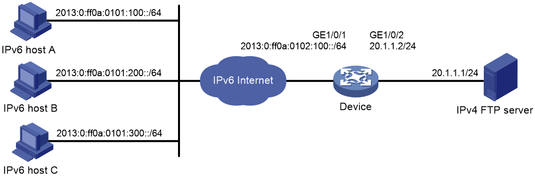
Network configuration
As shown in Figure 7, a company upgrades the network to IPv6 and has IPv4 addresses from 10.1.1.1 to 10.1.1.3.
To allow IPv6 hosts on subnet 2013::/96 to access the IPv4 Internet, configure the following AFT policies on the router:
· Configure a NAT64 prefix to translate IPv4 addresses of IPv4 servers to IPv6 addresses.
· Configure an IPv6-to-IPv4 source address dynamic translation policy to translate source IPv6 addresses of IPv6-initiated packets to IPv4 addresses in the range of 10.1.1.1 to 10.1.1.3.

Procedure
# Specify IP addresses for the interfaces on the router. (Details not shown.)
# Configure a static route from subnet 2013::/96 to NAT64 prefix 2012::/96 so that IPv6 packets destined for the IPv4 Internet will be sent to the device for AFT. (Details not shown.)
# Create AFT address group 0, and add the address range from 10.1.1.1 to 10.1.1.3 to the group.
<Router> system-view
[Router] aft address-group 0
[Router-aft-address-group-0] address 10.1.1.1 10.1.1.3
[Router-aft-address-group-0] quit
# Configure IPv6 ACL 2000 to permit IPv6 packets only from subnet 2013::/96 to pass through.
[Router] acl ipv6 basic 2000
[Router-acl-ipv6-basic-2000] rule permit source 2013:: 96
[Router-acl-ipv6-basic-2000] rule deny
[Router-acl-ipv6-basic-2000] quit
# Configure the router to translate source IPv6 addresses of packets permitted by IPv6 ACL 2000 to IPv4 addresses in address group 0.
[Router] aft v6tov4 source acl ipv6 number 2000 address-group 0
# Configure the router to use NAT64 prefix 2012::/96 to translate destination IPv6 addresses of IPv6 packets.
[Router] aft prefix-nat64 2012:: 96
# Enable AFT on GigabitEthernet 1/0/1, which is connected to the IPv6 network.
[Router] interface gigabitethernet 1/0/1
[Router-GigabitEthernet1/0/1] aft enable
[Router-GigabitEthernet1/0/1] quit
# Enable AFT on GigabitEthernet 1/0/2, which is connected to the IPv4 Internet.
[Router] interface gigabitethernet 1/0/2
[Router-GigabitEthernet1/0/2] aft enable
[Router-GigabitEthernet1/0/2] quit
Verifying the configuration
# Verify the connectivity between IPv6 hosts and IPv4 servers. This example pings IPv4 server A from IPv6 host A.
D:\>ping 2012::20.1.1.1
Pinging 2012::20.1.1.1 with 32 bytes of data:
Reply from 2012::20.1.1.1: time=3ms
Reply from 2012::20.1.1.1: time=3ms
Reply from 2012::20.1.1.1: time=3ms
Reply from 2012::20.1.1.1: time=3ms
# Display detailed information about IPv6 AFT sessions on the router.
[Router] display aft session ipv6 verbose
Initiator:
Source IP/port: 2013::100/0
Destination IP/port: 2012::1401:0101/32768
VPN instance/VLAN ID/Inline ID: -/-/-
Protocol: IPV6-ICMP(58)
Inbound interface: GigabitEthernet1/0/1
Source security zone: -
Responder:
Source IP/port: 2012::1401:0101/0
Destination IP/port: 2013::100/33024
VPN instance/VLAN ID/Inline ID: -/-/-
Protocol: IPV6-ICMP(58)
Inbound interface: GigabitEthernet1/0/2
Source security zone: -
State: ICMPV6_REPLY
Application: ICMP
Rule ID: -/-/-
Rule name:
Start time: 2014-03-13 08:52:59 TTL: 23s
Initiator->Responder: 4 packets 320 bytes
Responder->Initiator: 4 packets 320 bytes
Total sessions found: 1
# Display detailed information about IPv4 AFT sessions on the router.
[Router] display aft session ipv4 verbose
Initiator:
Source IP/port: 10.1.1.1/1025
Destination IP/port: 20.1.1.1/2048
DS-Lite tunnel peer: -
VPN instance/VLAN ID/Inline ID: -/-/-
Protocol: ICMP(1)
Inbound interface: GigabitEthernet1/0/1
Source security zone: -
Responder:
Source IP/port: 20.1.1.1/1025
Destination IP/port: 10.1.1.1/0
DS-Lite tunnel peer: -
VPN instance/VLAN ID/Inline ID: -/-/-
Protocol: ICMP(1)
Inbound interface: GigabitEthernet1/0/2
Source security zone: -
State: ICMP_REPLY
Application: ICMP
Rule ID: -/-/-
Rule name:
Start time: 2014-03-13 08:52:59 TTL: 27s
Initiator->Responder: 4 packets 240 bytes
Responder->Initiator: 4 packets 240 bytes
Total sessions found: 1
Example: Providing FTP service from an IPv6 network to the IPv4 Internet
Network configuration
As shown in Figure 8, a company upgrades the network to IPv6, and it has an IPv4 address 10.1.1.1.
To allow the IPv6 FTP server to provide FTP services to IPv4 hosts, configure the following AFT policies on the router:
· Map the IPv6 FTP server's IPv6 address and TCP port number to the company's IPv4 address and TCP port number.
· Configure a NAT64 prefix to translate source IPv4 addresses of IPv4 packets to source IPv6 addresses.

Procedure
# Specify IP addresses for the interfaces on the router. (Details not shown.)
# Configure a static route from subnet 20.1.1.1/24 to IP address 10.1.1.1 so that IPv4 packets destined for the IPv6 FTP server will be sent to the device for AFT. (Details not shown.)
# Map IPv4 address 10.1.1.1 with TCP port 21 to IPv6 address 2013::102 with TCP port 21 for the IPv6 internal FTP server.
<Router> system-view
[Router] aft v6server protocol tcp 10.1.1.1 21 2013::102 21
# Configure the router to use NAT64 prefix 2012:: 96 to translate source addresses of IPv4 packets.
[Router] aft prefix-nat64 2012:: 96
# Enable AFT on GigabitEthernet 1/0/1, which is connected to the IPv4 Internet.
[Router] interface gigabitethernet 1/0/1
[Router-GigabitEthernet1/0/1] aft enable
[Router-GigabitEthernet1/0/1] quit
# Enable AFT on GigabitEthernet 1/0/2, which is connected to the IPv6 FTP server.
[Router] interface gigabitethernet 1/0/2
[Router-GigabitEthernet1/0/2] aft enable
[Router-GigabitEthernet1/0/2] quit
Verifying the configuration
# Verify that IPv4 hosts can use FTP to access the IPv6 FTP server. (Details not shown.)
# Display detailed information about IPv6 AFT sessions on the router.
[Router] display aft session ipv4 verbose
Initiator:
Source IP/port: 20.1.1.1/11025
Destination IP/port: 10.1.1.1/21
DS-Lite tunnel peer: -
VPN instance/VLAN ID/Inline ID: -/-/-
Protocol: TCP(6)
Inbound interface: GigabitEthernet1/0/1
Source security zone: -
Responder:
Source IP/port: 10.1.1.1/21
Destination IP/port: 20.1.1.1/11025
DS-Lite tunnel peer: -
VPN instance/VLAN ID/Inline ID: -/-/-
Protocol: TCP(6)
Inbound interface: GigabitEthernet1/0/2
Source security zone: -
State: TCP_ESTABLISHED
Application: FTP
Rule ID: -/-/-
Rule name:
Start time: 2014-03-13 09:07:30 TTL: 3577s
Initiator->Responder: 3 packets 124 bytes
Responder->Initiator: 2 packets 108 bytes
Total sessions found: 1
# Display detailed information about IPv4 AFT sessions on the router.
[Router] display aft session ipv6 verbose
Initiator:
Source IP/port: 2012::1401:0101/1029
Destination IP/port: 2013::102/21
VPN instance/VLAN ID/Inline ID: -/-/-
Protocol: TCP(6)
Inbound interface: GigabitEthernet1/0/1
Source security zone: -
Responder:
Source IP/port: 2013::102/21
Destination IP/port: 2012::1401:0101/1029
VPN instance/VLAN ID/Inline ID: -/-/-
Protocol: TCP(6)
Inbound interface: GigabitEthernet1/0/2
Source security zone: -
State: TCP_ESTABLISHED
Application: FTP
Rule ID: -/-/-
Rule name:
Start time: 2014-03-13 09:07:30 TTL: 3582s
Initiator->Responder: 3 packets 184 bytes
Responder->Initiator: 2 packets 148 bytes
Total sessions found: 1
Example: Allowing mutual access between IPv4 and IPv6 networks
Network configuration
As shown in Figure 9, a company deploys both an IPv4 network and an IPv6 network.
To allow mutual access between the IPv4 network and the IPv6 network, configure the following AFT policies on the router:
· Assign an IVI prefix and an IPv4 subnet to the IPv6 network. Each IPv6 host uses the IPv6 addresses formed by the IVI prefix and an IPv4 address on the IPv4 subnet.
· Configure a NAT64 prefix to translate source IPv4 addresses of packets initiated by the IPv4 network to IPv6 addresses.

Procedure
# Specify IP addresses for the interfaces on the router. The IPv6 addresses for IPv6 hosts are calculated by the IVI prefix 2013::/32 and IPv4 addresses in the range of 20.1.1.0/24. (Details not shown.)
# Configure a static route from subnet 10.1.1.1/24 to subnet 20.1.1.0/24 so that IPv4 packets destined for the IPv6 network will be sent to the device for AFT. (Details not shown.)
# Configure a static route from the IPv6 network to NAT64 prefix 2012::/96 so that IPv6 packets destined for the IPv4 network will be sent to the device for AFT. (Details not shown.)
# Configure IPv4 ACL 2000 to permits all IPv4 packets to pass through.
<Router> system-view
[Router] acl basic 2000
[Router-acl-ipv4-basic-2000] rule permit
[Router-acl-ipv4-basic-2000] quit
# Configure the router to use NAT64 prefix 2012:: 96 to translate source addresses of IPv4 packets. The router also uses the prefix to translate destination addresses of IPv6 packets.
[Router] aft prefix-nat64 2012:: 96
# Configure the router to use IVI prefix 2013:: to translate source addresses of IPv6 packets.
[Router] aft prefix-ivi 2013::
# Configure the router to use IVI prefix 2013:: to translate destination addresses of packets permitted by IPv4 ACL 2000.
[Router] aft v4tov6 destination acl number 2000 prefix-ivi 2013::
# Enable AFT on GigabitEthernet1/0/1, which is connected to the IPv4 network.
[Router] interface gigabitethernet 1/0/1
[Router-GigabitEthernet1/0/1] aft enable
[Router-GigabitEthernet1/0/1] quit
# Enable AFT on GigabitEthernet1/0/2, which is connected to the IPv6 network.
[Router] interface gigabitethernet 1/0/2
[Router-GigabitEthernet1/0/2] aft enable
[Router-GigabitEthernet1/0/2] quit
Verifying the configuration
# Verify the connectivity between IPv6 hosts and IPv4 hosts. This example pings IPv4 host A from IPv6 host A.
D:\>ping 2012::a01:0101
Pinging 2012::a01:0101 with 32 bytes of data:
Reply from 2012::a01:0101: time=3ms
Reply from 2012::a01:0101: time=3ms
Reply from 2012::a01:0101: time=3ms
Reply from 2012::a01:0101: time=3ms
# Display information about IPv6 AFT sessions on the router.
[Router] display aft session ipv6 verbose
Initiator:
Source IP/port: 2013:0:FF14:0101:0100::/0
Destination IP/port: 2012::0a01:0101/32768
VPN instance/VLAN ID/Inline ID: -/-/-
Protocol: IPV6-ICMP(58)
Inbound interface: GigabitEthernet1/0/2
Source security zone: -
Responder:
Source IP/port: 2012::0a01:0101/0
Destination IP/port: 2013:0:FF14:0101:0100::/33024
VPN instance/VLAN ID/Inline ID: -/-/-
Protocol: IPV6-ICMP(58)
Inbound interface: GigabitEthernet1/0/1
Source security zone: -
State: ICMPV6_REPLY
Application: ICMP
Rule ID: -/-/-
Rule name:
Start time: 2014-03-13 08:52:59 TTL: 23s
Initiator->Responder: 4 packets 320 bytes
Responder->Initiator: 4 packets 320 bytes
Total sessions found: 1
# Display information about IPv4 AFT sessions on the router.
[Router] display aft session ipv4 verbose
Initiator:
Source IP/port: 20.1.1.1/1025
Destination IP/port: 10.1.1.1/2048
DS-Lite tunnel peer: -
VPN instance/VLAN ID/Inline ID: -/-/-
Protocol: ICMP(1)
Inbound interface: GigabitEthernet1/0/2
Source security zone: -
Responder:
Source IP/port: 10.1.1.1/1025
Destination IP/port: 20.1.1.1/0
DS-Lite tunnel peer: -
VPN instance/VLAN ID/Inline ID: -/-/-
Protocol: ICMP(1)
Inbound interface: GigabitEthernet1/0/1
Source security zone: -
State: ICMP_REPLY
Application: ICMP
Rule ID: -/-/-
Rule name:
Start time: 2014-03-13 08:52:59 TTL: 27s
Initiator->Responder: 4 packets 240 bytes
Responder->Initiator: 4 packets 240 bytes
Total sessions found: 1
Example: Allowing IPv6 Internet access from an IPv4 network
Network configuration
As shown in Figure 10, a company deploys an IPv4 network, and the Internet migrates to IPv6.
To allow IPv4 hosts to access the IPv6 server in the IPv6 Internet, configure the following AFT policies on the router:
· Configure an IPv4-to-IPv6 source address translation policy.
· Configure an IPv6-to-IPv4 source address static mapping for the IPv6 server.

Procedure
# Specify IP addresses for the interfaces on the router. (Details not shown.)
# Configure a static route from subnet 10.1.1.1/24 to IP address 20.1.1.1 so that IPv4 packets destined for the IPv6 server will be sent to the device for AFT. (Details not shown.)
# Configure IPv4 ACL 2000 to permit IPv4 packets only from subnet 10.1.1.0/24 to pass through.
<Router> system-view
[Router] acl basic 2000
[Router-acl-ipv4-basic-2000] rule permit source 10.1.1.0 0.0.0.255
[Router-acl-ipv4-basic-2000] rule deny
[Router-acl-ipv4-basic-2000] quit
# Configure NAT64 prefix 2012:: 96.
[Router] aft prefix-nat64 2012:: 96
# Configure the router to use NAT64 prefix 2012:: 96 to translate source addresses of packets permitted by IPv4 ACL 2000.
[Router] aft v4tov6 source acl number 2000 prefix-nat64 2012:: 96
# Map source IPv6 address 2013:0:ff14:0101:100:: to source IPv4 address 20.1.1.1.
[Router] aft v6tov4 source 2013:0:ff14:0101:100::1 20.1.1.1
# Enable AFT on GigabitEthernet 1/0/1, which is connected to the IPv4 network.
[Router] interface gigabitethernet 1/0/1
[Router-GigabitEthernet1/0/1] aft enable
[Router-GigabitEthernet1/0/1] quit
# Enable AFT on GigabitEthernet 1/0/2, which is connected to the IPv6 Internet.
[Router] interface gigabitethernet 1/0/2
[Router-GigabitEthernet1/0/2] aft enable
[Router-GigabitEthernet1/0/2] quit
Verifying the configuration
# Verify the connectivity between the IPv4 hosts and the IPv6 server. This example uses the ping utility on an IPv4 host.
D:\>ping 20.1.1.1
Pinging 20.1.1.1 with 32 bytes of data:
Reply from 20.1.1.1: bytes=32 time=14ms TTL=63
Reply from 20.1.1.1: bytes=32 time=1ms TTL=63
Reply from 20.1.1.1: bytes=32 time=1ms TTL=63
Reply from 20.1.1.1: bytes=32 time=1ms TTL=63
# Display detailed information about IPv6 AFT sessions on the router.
[Router] display aft session ipv4 verbose
Initiator:
Source IP/port: 10.1.1.1/1025
Destination IP/port: 20.1.1.1/2048
DS-Lite tunnel peer: -
VPN instance/VLAN ID/Inline ID: -/-/-
Protocol: ICMP(1)
Inbound interface: GigabitEthernet1/0/1
Source security zone: -
Responder:
Source IP/port: 20.1.1.1/1025
Destination IP/port: 10.1.1.1/0
DS-Lite tunnel peer: -
VPN instance/VLAN ID/Inline ID: -/-/-
Protocol: ICMP(1)
Inbound interface: GigabitEthernet1/0/2
Source security zone: -
State: ICMP_REPLY
Application: ICMP
Rule ID: -/-/-
Rule name:
Start time: 2014-03-13 08:52:59 TTL: 27s
Initiator->Responder: 4 packets 240 bytes
Responder->Initiator: 4 packets 240 bytes
Total sessions found: 1
# Display detailed information about IPv4 AFT sessions on the router.
[Router] display aft session ipv6 verbose
Initiator:
Source IP/port: 2012::0A01:0101/0
Destination IP/port: 2013:0:FF14:0101:0100::/32768
VPN instance/VLAN ID/Inline ID: -/-/-
Protocol: IPV6-ICMP(58)
Inbound interface: GigabitEthernet1/0/1
Source security zone: -
Responder:
Source IP/port: 2013:0:FF14:0101:0100::/0
Destination IP/port: 2012::0A01:0101/33024
VPN instance/VLAN ID/Inline ID: -/-/-
Protocol: IPV6-ICMP(58)
Inbound interface: GigabitEthernet1/0/2
Source security zone: -
State: ICMPV6_REPLY
Application: ICMP
Rule ID: -/-/-
Rule name:
Start time: 2014-03-13 08:52:59 TTL: 23s
Initiator->Responder: 4 packets 320 bytes
Responder->Initiator: 4 packets 320 bytes
Total sessions found: 1
Example: Providing FTP service from an IPv4 network to the IPv6 Internet
Network configuration
As shown in Figure 11, a company deploys an IPv4 network, and it has an IPv6 address 2012::1. The Internet migrates to IPv6.
To allow the IPv4 FTP server to provide FTP services to IPv6 hosts, configure the following AFT policies on the router:
· Configure an IPv4-to-IPv6 source address static mapping for the IPv4 FTP server. The router uses the mapping to translate the destination IPv6 address of IPv6-initiated addresses to the IPv4 address.
· Configure an IPv6-to-IPv4 source address dynamic translation policy. The router translates source IPv6 addresses of IPv6-initiated packets to source IPv4 addresses 30.1.1.1 and 30.1.1.2.
Procedure
# Specify IP addresses for the interfaces on the router. (Details not shown.)
# Configure a static route from the IPv6 host subnet to IPv6 address 2012::1 so that IPv6 packets destined for the IPv4 FTP server will be sent to the device for AFT. (Details not shown.)
# Map source IPv4 address 20.1.1.1 to source IPv6 address 2012::1.
<Router> system-view
[Router] aft v4tov6 source 20.1.1.1 2012::1
# Configure address group 0, and add the address range from 30.1.1.1 to 30.1.1.2 to the group.
[Router] aft address-group 0
[Router-aft-address-group-0] address 30.1.1.1 30.1.1.2
[Router-aft-address-group-0] quit
# Configure IPv6 ACL 2000 to permit all IPv6 packets to pass through.
[Router] acl ipv6 basic 2000
[Router-acl-ipv6-basic-2000] rule permit
[Router-acl-ipv6-basic-2000] quit
# Configure the router to translate source addresses of IPv6 packets permitted by IPv6 ACL 2000 to IPv4 addresses in address group 0.
[Router] aft v6tov4 source acl ipv6 number 2000 address-group 0
# Enable AFT on GigabitEthernet 1/0/1, which is connected to the IPv6 Internet.
[Router] interface gigabitethernet 1/0/1
[Router-GigabitEthernet1/0/1] aft enable
[Router-GigabitEthernet1/0/1] quit
# Enable AFT on GigabitEthernet 1/0/2, which is connected to the IPv4 network.
[Router] interface gigabitethernet 1/0/2
[Router-GigabitEthernet1/0/2] aft enable
[Router-GigabitEthernet1/0/2] quit
Verifying the configuration
# Verify the connectivity between the IPv6 hosts and the IPv4 FTP server. For example, ping the IPv4 FTP server from IPv6 host A.
D:\>ping 2012::1
Pinging 2012::1 with 32 bytes of data:
Reply from 2012::1: time=3ms
Reply from 2012::1: time=3ms
Reply from 2012::1: time=3ms
Reply from 2012::1: time=3ms
# Display detailed information about IPv6 AFT sessions on the router.
[Router] display aft session ipv6 verbose
Initiator:
Source IP/port: 2013:0:FF0A:0101:0100::/1029
Destination IP/port: 2012::1/21
VPN instance/VLAN ID/Inline ID: -/-/-
Protocol: IPV6-ICMP(58)
Inbound interface: GigabitEthernet1/0/1
Source security zone: -
Responder:
Source IP/port: 2012::1/21
Destination IP/port: 2013:0:FF0A:0101:0100::/1029
VPN instance/VLAN ID/Inline ID: -/-/-
Protocol: IPV6-ICMP(58)
Inbound interface: GigabitEthernet1/0/2
Source security zone: -
State: ICMPV6_REPLY
Application: ICMP
Rule ID: -/-/-
Rule name:
Start time: 2014-03-13 09:07:30 TTL: 3582s
Initiator->Responder: 3 packets 184 bytes
Responder->Initiator: 2 packets 148 bytes
Total sessions found: 1
# Display detailed information about IPv4 AFT sessions on the router.
[Router] display aft session ipv4 verbose
Initiator:
Source IP/port: 30.1.1.1/11025
Destination IP/port: 20.1.1.1/21
DS-Lite tunnel peer: -
VPN instance/VLAN ID/Inline ID: -/-/-
Protocol: ICMP(1)
Inbound interface: GigabitEthernet1/0/1
Source security zone: -
Responder:
Source IP/port: 20.1.1.1/21
Destination IP/port: 30.1.1.1/11025
DS-Lite tunnel peer: -
VPN instance/VLAN ID/Inline ID: -/-/-
Protocol: ICMP(1)
Inbound interface: GigabitEthernet1/0/2
Source security zone: -
State: ICMP_REPLY
Application: ICMP
Rule ID: -/-/-
Rule name:
Start time: 2014-03-13 09:07:30 TTL: 3577s
Initiator->Responder: 3 packets 124 bytes
Responder->Initiator: 2 packets 108 bytes
Total sessions found: 1
AFT configuration examples
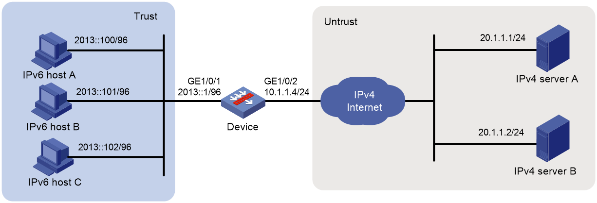
Example: Allowing IPv4 Internet access from an IPv6 network
Network configuration
As shown in Figure 12, a company upgrades the network to IPv6 and has IPv4 addresses from 10.1.1.1 to 10.1.1.3.
To allow IPv6 hosts on subnet 2013::/96 to access the IPv4 Internet, configure the following AFT policies on the device:
· Configure a NAT64 prefix to translate IPv4 addresses of IPv4 servers to IPv6 addresses.
· Configure an IPv6-to-IPv4 source address dynamic translation policy to translate source IPv6 addresses of IPv6-initiated packets to IPv4 addresses in the range of 10.1.1.1 to 10.1.1.3.
Procedure
1. Assign IP addresses to interfaces:
# Assign an IP address to interface GigabitEthernet 1/0/1.
<Device> system-view
[Device] interface gigabitethernet 1/0/1
[Device-GigabitEthernet1/0/1] ipv6 address 2013::1 96
[Device-GigabitEthernet1/0/1] quit
# Assign IP addresses to other interfaces in the same way. (Details not shown.)
2. Add interfaces to security zones.
[Device] security-zone name trust
[Device-security-zone-Trust] import interface gigabitethernet 1/0/1
[Device-security-zone-Trust] quit
[Device] security-zone name untrust
[Device-security-zone-Untrust] import interface gigabitethernet 1/0/2
[Device-security-zone-Untrust] quit
3. Configure settings for routing.
This example configures a static route with next hop address 10.1.1.100.
[Device] ip route-static 20.1.1.0 24 10.1.1.100
4. Configure security policies:
# In the IPv6 security policy, configure a rule named aftlocalin to allow the device to perform AFT on the IPv6 host traffic destined for the IPv4 servers.
[Device] security-policy ipv6
[Device-security-policy-ipv6] rule name aftlocalin
[Device-security-policy-ipv6-1-aftlocalin] source-zone trust
[Device-security-policy-ipv6-1-aftlocalin] destination-zone local
[Device-security-policy-ipv6-1-aftlocalin] source-ip-subnet 2013:: 96
[Device-security-policy-ipv6-1-aftlocalin] destination-ip-host 2012::20.1.1.1
[Device-security-policy-ipv6-1-aftlocalin] destination-ip-host 2012::20.1.1.2
[Device-security-policy-ipv6-1-aftlocalin] action pass
[Device-security-policy-ipv6-1-aftlocalin] quit
[Device-security-policy-ipv6] quit
# In the IPv6 security policy, configure a rule named aftlocalout to allow the device to forward the AFT-translated packets to the IPv4 servers.
[Device] security-policy ip
[Device-security-policy-ip] rule name aftlocalout
[Device-security-policy-ip-1-aftlocalout] source-zone local
[Device-security-policy-ip-1-aftlocalout] destination-zone untrust
[Device-security-policy-ip-1-aftlocalout] source-ip-host 10.1.1.1
[Device-security-policy-ip-1-aftlocalout] source-ip-host 10.1.1.2
[Device-security-policy-ip-1-aftlocalout] source-ip-host 10.1.1.3
[Device-security-policy-ip-1-aftlocalout] destination-ip-host 20.1.1.1
[Device-security-policy-ip-1-aftlocalout] destination-ip-host 20.1.1.2
[Device-security-policy-ip-1-aftlocalout] action pass
[Device-security-policy-ip-1-aftlocalout] quit
[Device-security-policy-ip] quit
5. Configure AFT settings:
# Create AFT address group 0, and add the address range from 10.1.1.1 to 10.1.1.3 to the group.
[Device] aft address-group 0
[Device-aft-address-group-0] address 10.1.1.1 10.1.1.3
[Device-aft-address-group-0] quit
# Configure IPv6 ACL 2000 to permit IPv6 packets only from subnet 2013::/96 to pass through.
[Device] acl ipv6 basic 2000
[Device-acl-ipv6-basic-2000] rule permit source 2013:: 96
[Device-acl-ipv6-basic-2000] rule deny
[Device-acl-ipv6-basic-2000] quit
# Configure the device to translate source IPv6 addresses of packets permitted by IPv6 ACL 2000 to IPv4 addresses in address group 0.
[Device] aft v6tov4 source acl ipv6 number 2000 address-group 0
# Configure the device to use NAT64 prefix 2012::/96 to translate destination IPv6 addresses of IPv6 packets.
[Device] aft prefix-nat64 2012:: 96
# Enable AFT on the interfaces connected to the IPv6 network and IPv4 Internet, respectively.
[Device] interface gigabitethernet 1/0/1
[Device-GigabitEthernet1/0/1] aft enable
[Device-GigabitEthernet1/0/1] quit
[Device] interface gigabitethernet 1/0/2
[Device-GigabitEthernet1/0/2] aft enable
[Device-GigabitEthernet1/0/2] quit
# Configure routes to make sure IPv6 hosts can reach IPv6 addresses that are translated by using the NAT64 prefix, and IPv4 servers can reach translated IPv4 addresses. (Details not shown.)
Verifying the configuration
# Verify the connectivity between IPv6 hosts and IPv4 servers. This example pings IPv4 server A from IPv6 host A.
D:\>ping 2012::20.1.1.1
Pinging 2012::20.1.1.1 with 32 bytes of data:
Reply from 2012::20.1.1.1: time=3ms
Reply from 2012::20.1.1.1: time=3ms
Reply from 2012::20.1.1.1: time=3ms
Reply from 2012::20.1.1.1: time=3ms
# Display detailed information about IPv6 AFT sessions on the device.
[Device] display aft session ipv6 verbose
Initiator:
Source IP/port: 2013::100/0
Destination IP/port: 2012::1401:0101/32768
VPN instance/VLAN ID/Inline ID: -/-/-
Protocol: IPV6-ICMP(58)
Inbound interface: GigabitEthernet1/0/1
Source security zone: Trust
Responder:
Source IP/port: 2012::1401:0101/0
Destination IP/port: 2013::100/33024
VPN instance/VLAN ID/Inline ID: -/-/-
Protocol: IPV6-ICMP(58)
Inbound interface: GigabitEthernet1/0/2
Source security zone: Local
State: ICMPV6_REPLY
Application: ICMP
Rule ID: -/-/-
Rule name:
Start time: 2014-03-13 08:52:59 TTL: 23s
Initiator->Responder: 4 packets 320 bytes
Responder->Initiator: 4 packets 320 bytes
Total sessions found: 1
# Display detailed information about IPv4 AFT sessions on the device.
[Device] display aft session ipv4 verbose
Initiator:
Source IP/port: 10.1.1.1/1025
Destination IP/port: 20.1.1.1/2048
DS-Lite tunnel peer: -
VPN instance/VLAN ID/Inline ID: -/-/-
Protocol: ICMP(1)
Inbound interface: GigabitEthernet1/0/1
Source security zone: Local
Responder:
Source IP/port: 20.1.1.1/1025
Destination IP/port: 10.1.1.1/0
DS-Lite tunnel peer: -
VPN instance/VLAN ID/Inline ID: -/-/-
Protocol: ICMP(1)
Inbound interface: GigabitEthernet1/0/2
Source security zone: Untrust
State: ICMP_REPLY
Application: ICMP
Rule ID: 0
Rule name: aftlocalout
Start time: 2014-03-13 08:52:59 TTL: 27s
Initiator->Responder: 4 packets 240 bytes
Responder->Initiator: 4 packets 240 bytes
Total sessions found: 1
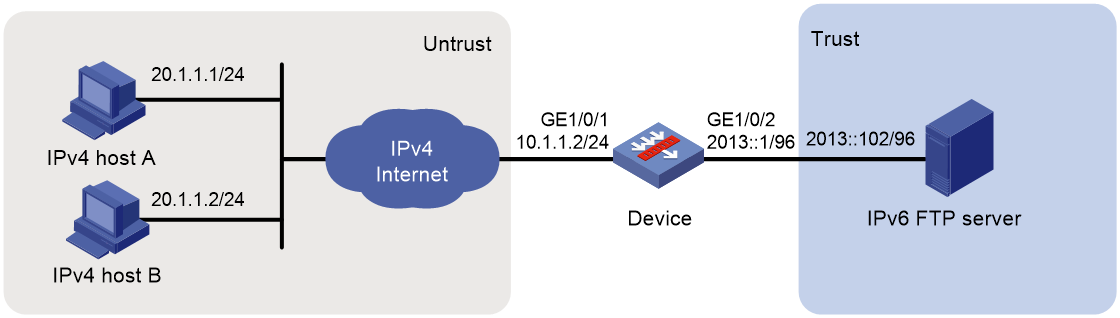
Example: Providing FTP service from an IPv6 network to the IPv4 Internet
Network configuration
As shown in Figure 13, a company upgrades the network to IPv6, and it has an IPv4 address 10.1.1.1.
To allow the IPv6 FTP server to provide FTP services to IPv4 hosts, configure the following AFT policies on the device:
· Map the IPv6 FTP server's IPv6 address and TCP port number to the company's IPv4 address and TCP port number.
· Configure a NAT64 prefix to translate source IPv4 addresses of IPv4 packets to source IPv6 addresses.
Procedure
1. Assign IP addresses to interfaces:
# Assign an IP address to interface GigabitEthernet 1/0/1.
<Device> system-view
[Device] interface gigabitethernet 1/0/1
[Device-GigabitEthernet1/0/1] ip address 10.1.1.2 24
[Device-GigabitEthernet1/0/1] quit
# Assign IP addresses to other interfaces in the same way. (Details not shown.)
2. Add interfaces to security zones.
[Device] security-zone name trust
[Device-security-zone-Trust] import interface gigabitethernet 1/0/2
[Device-security-zone-Trust] quit
[Device] security-zone name untrust
[Device-security-zone-Untrust] import interface gigabitethernet 1/0/1
[Device-security-zone-Untrust] quit
3. Configure security policies:
# In the IPv4 security policy, configure a rule named aftlocalin to allow the device to perform AFT on the IPv4 traffic destined for the IPv6 FTP server.
[Device] security-policy ip
[Device-security-policy-ip] rule name aftlocalin
[Device-security-policy-ip-1-aftlocalin] source-zone untrust
[Device-security-policy-ip-1-aftlocalin] destination-zone local
[Device-security-policy-ip-1-aftlocalin] destination-ip-host 10.1.1.1
[Device-security-policy-ip-1-aftlocalin] action pass
[Device-security-policy-ip-1-aftlocalin] quit
[Device-security-policy-ip] quit
# In the IPv6 security policy, configure a rule named aftlocalout to allow the device to forward the AFT-translated packets to the IPv6 server.
[Device] security-policy ipv6
[Device-security-policy-ipv6] rule name aftlocalout
[Device-security-policy-ipv6-1-aftlocalout] source-zone local
[Device-security-policy-ipv6-1-aftlocalout] destination-zone trust
[Device-security-policy-ipv6-1-aftlocalout] source-ip-subnet 2012:: 96
[Device-security-policy-ipv6-1-aftlocalout] destination-ip-host 2013::102
[Device-security-policy-ipv6-1-aftlocalout] action pass
[Device-security-policy-ipv6-1-aftlocalout] quit
[Device-security-policy-ipv6] quit
4. Configure AFT settings:
# Map IPv4 address 10.1.1.1 with TCP port 21 to IPv6 address 2013::102 with TCP port 21 for the IPv6 internal FTP server.
[Device] aft v6server protocol tcp 10.1.1.1 21 2013::102 21
# Configure the device to use NAT64 prefix 2012:: 96 to translate source addresses of IPv4 packets.
[Device] aft prefix-nat64 2012:: 96
# Enable AFT on the interfaces connected to the IPv4 Internet and IPv6 network, respectively.
[Device] interface gigabitethernet 1/0/1
[Device-GigabitEthernet1/0/1] aft enable
[Device-GigabitEthernet1/0/1] quit
[Device] interface gigabitethernet 1/0/2
[Device-GigabitEthernet1/0/2] aft enable
[Device-GigabitEthernet1/0/2] quit
Verifying the configuration
# Verify that IPv4 hosts can use FTP to access the IPv6 FTP server. (Details not shown.)
# Display detailed information about IPv6 AFT sessions on the device.
[Device] display aft session ipv4 verbose
Initiator:
Source IP/port: 20.1.1.1/11025
Destination IP/port: 10.1.1.1/21
DS-Lite tunnel peer: -
VPN instance/VLAN ID/Inline ID: -/-/-
Protocol: TCP(6)
Inbound interface: GigabitEthernet1/0/1
Source security zone: Untrust
Responder:
Source IP/port: 10.1.1.1/21
Destination IP/port: 20.1.1.1/11025
DS-Lite tunnel peer: -
VPN instance/VLAN ID/Inline ID: -/-/-
Protocol: TCP(6)
Inbound interface: GigabitEthernet1/0/2
Source security zone: Local
State: TCP_ESTABLISHED
Application: FTP
Rule ID: -/-/-
Rule name:
Start time: 2014-03-13 09:07:30 TTL: 3577s
Initiator->Responder: 3 packets 124 bytes
Responder->Initiator: 2 packets 108 bytes
Total sessions found: 1
# Display detailed information about IPv4 AFT sessions on the device.
[Device] display aft session ipv6 verbose
Initiator:
Source IP/port: 2012::1401:0101/1029
Destination IP/port: 2013::102/21
VPN instance/VLAN ID/Inline ID: -/-/-
Protocol: TCP(6)
Inbound interface: GigabitEthernet1/0/1
Source security zone: Local
Responder:
Source IP/port: 2013::102/21
Destination IP/port: 2012::1401:0101/1029
VPN instance/VLAN ID/Inline ID: -/-/-
Protocol: TCP(6)
Inbound interface: GigabitEthernet1/0/2
Source security zone: Trust
State: TCP_ESTABLISHED
Application: FTP
Rule ID: 0
Rule name: aftlocalout
Start time: 2014-03-13 09:07:30 TTL: 3582s
Initiator->Responder: 3 packets 184 bytes
Responder->Initiator: 2 packets 148 bytes
Total sessions found: 1
Example: Allowing mutual access between IPv4 and IPv6 networks
Network configuration
As shown in Figure 14, a company deploys both an IPv4 network and an IPv6 network.
To allow mutual access between the IPv4 network and the IPv6 network, configure the following AFT policies on the device:
· Assign an IVI prefix and an IPv4 subnet to the IPv6 network. Each IPv6 host uses the IPv6 addresses formed by the IVI prefix and an IPv4 address on the IPv4 subnet.
· Configure a NAT64 prefix to translate source IPv4 addresses of packets initiated by the IPv4 network to IPv6 addresses.
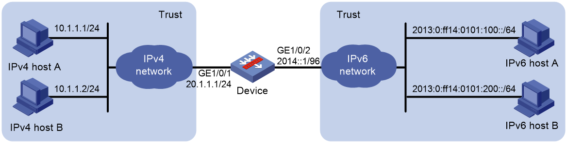
Procedure
1. Assign IP addresses to interfaces:
# Assign an IP address to interface GigabitEthernet 1/0/1.
<Device> system-view
[Device] interface gigabitethernet 1/0/1
[Device-GigabitEthernet1/0/1] ip address 20.1.1.1 24
[Device-GigabitEthernet1/0/1] quit
# Assign IP addresses to other interfaces in the same way. (Details not shown.)
2. Add interfaces to security zones.
[Device] security-zone name trust
[Device-security-zone-Trust] import interface gigabitethernet 1/0/1
[Device-security-zone-Trust] import interface gigabitethernet 1/0/2
[Device-security-zone-Trust] quit
3. Configure settings for routing.
This example configures an IPv6 static route (with next hop address 2014::100) and an IPv4 static route (with next hop address 20.1.1.2).
[Device] ipv6 route-static 2013:: 32 2014::100
[Device] ip route-static 10.1.1.0 24 20.1.1.2
4. Configure security policies to allow the device to permit IPv4-to-IPv6 traffic:
# In the IPv4 security policy, configure a rule named aftlocalin4 to allow the device to perform AFT on the IPv4 traffic destined for the IPv6 hosts.
[Device] security-policy ip
[Device-security-policy-ip] rule name aftlocalin4
[Device-security-policy-ip-1-aftlocalin4] source-zone trust
[Device-security-policy-ip-1-aftlocalin4] destination-zone local
[Device-security-policy-ip-1-aftlocalin4] source-ip-subnet 10.1.1.0 24
[Device-security-policy-ip-1-aftlocalin4] destination-ip-subnet 20.1.1.0 24
[Device-security-policy-ip-1-aftlocalin4] action pass
[Device-security-policy-ip-1-aftlocalin4] quit
[Device-security-policy-ip] quit
# In the IPv6 security policy, configure a rule named aftlocalout6 to allow the device to forward the AFT-translated packets to the IPv6 hosts.
[Device] security-policy ipv6
[Device-security-policy-ipv6] rule name aftlocalout6
[Device-security-policy-ipv6-1-aftlocalout6] source-zone local
[Device-security-policy-ipv6-1-aftlocalout6] destination-zone trust
[Device-security-policy-ipv6-1-aftlocalout6] source-ip-subnet 2012:: 96
[Device-security-policy-ipv6-1-aftlocalout6] destination-ip-subnet 2013:: 32
[Device-security-policy-ipv6-1-aftlocalout6] action pass
[Device-security-policy-ipv6-1-local-ipv6] quit
5. Configure security policies to allow the device to permit IPv6-to-IPv4 traffic:
# In the IPv6 security policy, configure a rule named aftlocalin6 to allow the device to perform AFT on the IPv6 traffic destined for the IPv4 hosts.
[Device-security-policy-ipv6] rule name aftlocalin6
[Device-security-policy-ipv6-2-aftlocalin6] source-zone trust
[Device-security-policy-ipv6-2-aftlocalin6] destination-zone local
[Device-security-policy-ipv6-2-aftlocalin6] source-ip-subnet 2013:: 32
[Device-security-policy-ipv6-2-aftlocalin6] destination-ip-subnet 2012:: 96
[Device-security-policy-ipv6-2-aftlocalin6] action pass
[Device-security-policy-ipv6-2-aftlocalin6] quit
[Device-security-policy-ipv6] quit
# In the IPv4 security policy, configure a rule named aftlocalout4 to allow the device to forward the AFT-translated packets to the IPv4 hosts.
[Device] security-policy ip
[Device-security-policy-ip] rule 2 name aftlocalout4
[Device-security-policy-ip-2-aftlocalout4] source-zone local
[Device-security-policy-ip-2-aftlocalout4] destination-zone trust
[Device-security-policy-ip-2-aftlocalout4] source-ip-subnet 20.1.1.0 24
[Device-security-policy-ip-2-aftlocalout4] destination-ip-subnet 10.1.1.0 24
[Device-security-policy-ip-2-aftlocalout4] action pass
[Device-security-policy-ip-2-aftlocalout4] quit
[Device-security-policy-ip] quit
6. Configure AFT settings:
# Configure IPv4 ACL 2000 to permits all IPv4 packets to pass through.
[Device] acl basic 2000
[Device-acl-ipv4-basic-2000] rule permit
[Device-acl-ipv4-basic-2000] quit
# Configure the device to use NAT64 prefix 2012:: 96 to translate source addresses of IPv4 packets. The device also uses the prefix to translate destination addresses of IPv6 packets.
[Device] aft prefix-nat64 2012:: 96
# Configure the device to use IVI prefix 2013:: to translate source addresses of IPv6 packets.
[Device] aft prefix-ivi 2013::
# Configure the device to use IVI prefix 2013:: to translate destination addresses of packets permitted by IPv4 ACL 2000.
[Device] aft v4tov6 destination acl number 2000 prefix-ivi 2013::
# Enable AFT on the interfaces connected to the IPv4 and IPv6 networks, respectively.
[Device] interface gigabitethernet 1/0/1
[Device-GigabitEthernet1/0/1] aft enable
[Device-GigabitEthernet1/0/1] quit
[Device] interface gigabitethernet 1/0/2
[Device-GigabitEthernet1/0/2] aft enable
[Device-GigabitEthernet1/0/2] quit
Verifying the configuration
# Verify the connectivity between IPv6 hosts and IPv4 hosts. This example pings IPv4 host A from IPv6 host A.
D:\>ping 2012::a01:0101
Pinging 2012::a01:0101 with 32 bytes of data:
Reply from 2012::a01:0101: time=3ms
Reply from 2012::a01:0101: time=3ms
Reply from 2012::a01:0101: time=3ms
Reply from 2012::a01:0101: time=3ms
# Display information about IPv6 AFT sessions on the device.
[Device] display aft session ipv6 verbose
Initiator:
Source IP/port: 2013:0:FF14:0101:0100::/0
Destination IP/port: 2012::0a01:0101/32768
VPN instance/VLAN ID/Inline ID: -/-/-
Protocol: IPV6-ICMP(58)
Inbound interface: GigabitEthernet1/0/2
Source security zone: Trust
Responder:
Source IP/port: 2012::0a01:0101/0
Destination IP/port: 2013:0:FF14:0101:0100::/33024
VPN instance/VLAN ID/Inline ID: -/-/-
Protocol: IPV6-ICMP(58)
Inbound interface: GigabitEthernet1/0/1
Source security zone: Local
State: ICMPV6_REPLY
Application: ICMP
Rule ID: -/-/-
Rule name:
Start time: 2014-03-13 08:52:59 TTL: 23s
Initiator->Responder: 4 packets 320 bytes
Responder->Initiator: 4 packets 320 bytes
Total sessions found: 1
# Display information about IPv4 AFT sessions on the device.
[Device] display aft session ipv4 verbose
Initiator:
Source IP/port: 20.1.1.1/1025
Destination IP/port: 10.1.1.1/2048
DS-Lite tunnel peer: -
VPN instance/VLAN ID/Inline ID: -/-/-
Protocol: ICMP(1)
Inbound interface: GigabitEthernet1/0/2
Source security zone: Local
Responder:
Source IP/port: 10.1.1.1/1025
Destination IP/port: 20.1.1.1/0
DS-Lite tunnel peer: -
VPN instance/VLAN ID/Inline ID: -/-/-
Protocol: ICMP(1)
Inbound interface: GigabitEthernet1/0/1
Source security zone: Trust
State: ICMP_REPLY
Application: ICMP
Rule ID: 2
Rule name: aftlocalout4
Start time: 2014-03-13 08:52:59 TTL: 27s
Initiator->Responder: 4 packets 240 bytes
Responder->Initiator: 4 packets 240 bytes
Total sessions found: 1
Example: Allowing IPv6 Internet access from an IPv4 network
Network configuration
As shown in Figure 15, a company deploys an IPv4 network, and the Internet migrates to IPv6.
To allow IPv4 hosts to access the IPv6 server in the IPv6 Internet, configure the following AFT policies on the device:
· Configure an IPv4-to-IPv6 source address dynamic translation policy.
· Configure an IPv6-to-IPv4 source address static mapping for the IPv6 server.
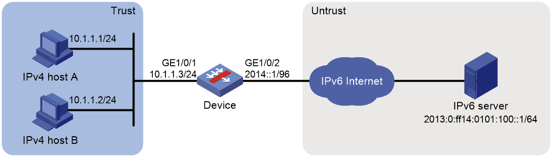
Procedure
1. Assign IP addresses to interfaces:
# Assign an IP address to interface GigabitEthernet 1/0/1.
<Device> system-view
[Device] interface gigabitethernet 1/0/1
[Device-GigabitEthernet1/0/1] ip address 10.1.1.3 24
[Device-GigabitEthernet1/0/1] quit
# Assign IP addresses to other interfaces in the same way. (Details not shown.)
2. Add interfaces to security zones.
[Device] security-zone name trust
[Device-security-zone-Trust] import interface gigabitethernet 1/0/1
[Device-security-zone-Trust] quit
[Device] security-zone name untrust
[Device-security-zone-Untrust] import interface gigabitethernet 1/0/2
[Device-security-zone-Untrust] quit
3. Configure settings for routing.
This example configures a static route with next hop address 2014::100.
[Device] ipv6 route-static 2013:0:ff14:0101:100:: 64 2014::100
4. Configure security policies:
# In the IPv4 security policy, configure a rule named aftlocalin to allow the device to perform AFT on the IPv4 host traffic destined for the IPv6 server.
[Device] security-policy ip
[Device-security-policy-ip] rule name aftlocalin
[Device-security-policy-ip-1-aftlocalin] source-zone trust
[Device-security-policy-ip-1-aftlocalin] destination-zone local
[Device-security-policy-ip-1-aftlocalin] source-ip-subnet 10.1.1.0 24
[Device-security-policy-ip-1-aftlocalin] destination-ip-host 20.1.1.1
[Device-security-policy-ip-1-aftlocalin] action pass
[Device-security-policy-ip-1-aftlocalin] quit
[Device-security-policy-ip] quit
# In the IPv6 security policy, configure a rule named aftlocalout to allow the device to forward the AFT-translated packets to the IPv6 server.
[Device] security-policy ipv6
[Device-security-policy-ipv6] rule name aftlocalout
[Device-security-policy-ipv6-1-aftlocalout] source-zone local
[Device-security-policy-ipv6-1-aftlocalout] destination-zone untrust
[Device-security-policy-ipv6-1-aftlocalout] source-ip-subnet 2012:: 96
[Device-security-policy-ipv6-1-aftlocalout] destination-ip-host 2013:0:ff14:0101:100::1
[Device-security-policy-ipv6-1-aftlocalout] action pass
[Device-security-policy-ipv6-1-aftlocalout] quit
[Device-security-policy-ipv6] quit
5. Configure AFT settings:
# Configure IPv4 ACL 2000 to permit IPv4 packets only from subnet 10.1.1.0/24 to pass through.
[Device] acl basic 2000
[Device-acl-ipv4-basic-2000] rule permit source 10.1.1.0 0.0.0.255
[Device-acl-ipv4-basic-2000] rule deny
[Device-acl-ipv4-basic-2000] quit
# Configure NAT64 prefix 2012:: 96.
[Device] aft prefix-nat64 2012:: 96
# Configure the device to use NAT64 prefix 2012:: 96 to translate source addresses of packets permitted by IPv4 ACL 2000.
[Device] aft v4tov6 source acl number 2000 prefix-nat64 2012:: 96
# Map source IPv6 address 2013:0:ff14:0101:100:: to source IPv4 address 20.1.1.1.
[Device] aft v6tov4 source 2013:0:ff14:0101:100::1 20.1.1.1
# Enable AFT on the interfaces connected to the IPv4 and IPv6 networks, respectively.
[Device] interface gigabitethernet 1/0/1
[Device-GigabitEthernet1/0/1] aft enable
[Device-GigabitEthernet1/0/1] quit
[Device] interface gigabitethernet 1/0/2
[Device-GigabitEthernet1/0/2] aft enable
[Device-GigabitEthernet1/0/2] quit
Verifying the configuration
# Verify the connectivity between the IPv4 hosts and the IPv6 server. This example uses the ping utility on an IPv4 host.
D:\>ping 20.1.1.1
Pinging 20.1.1.1 with 32 bytes of data:
Reply from 20.1.1.1: bytes=32 time=14ms TTL=63
Reply from 20.1.1.1: bytes=32 time=1ms TTL=63
Reply from 20.1.1.1: bytes=32 time=1ms TTL=63
Reply from 20.1.1.1: bytes=32 time=1ms TTL=63
# Display detailed information about IPv6 AFT sessions on the device.
[Device] display aft session ipv4 verbose
Initiator:
Source IP/port: 10.1.1.1/1025
Destination IP/port: 20.1.1.1/2048
DS-Lite tunnel peer: -
VPN instance/VLAN ID/Inline ID: -/-/-
Protocol: ICMP(1)
Inbound interface: GigabitEthernet1/0/1
Source security zone: Trust
Responder:
Source IP/port: 20.1.1.1/1025
Destination IP/port: 10.1.1.1/0
DS-Lite tunnel peer: -
VPN instance/VLAN ID/Inline ID: -/-/-
Protocol: ICMP(1)
Inbound interface: GigabitEthernet1/0/2
Source security zone: Local
State: ICMP_REPLY
Application: ICMP
Rule ID: -/-/-
Rule name:
Start time: 2014-03-13 08:52:59 TTL: 27s
Initiator->Responder: 4 packets 240 bytes
Responder->Initiator: 4 packets 240 bytes
Total sessions found: 1
# Display detailed information about IPv4 AFT sessions on the device.
[Device] display aft session ipv6 verbose
Initiator:
Source IP/port: 2012::0A01:0101/0
Destination IP/port: 2013:0:FF14:0101:0100::/32768
VPN instance/VLAN ID/Inline ID: -/-/-
Protocol: IPV6-ICMP(58)
Inbound interface: GigabitEthernet1/0/1
Source security zone: Local
Responder:
Source IP/port: 2013:0:FF14:0101:0100::/0
Destination IP/port: 2012::0A01:0101/33024
VPN instance/VLAN ID/Inline ID: -/-/-
Protocol: IPV6-ICMP(58)
Inbound interface: GigabitEthernet1/0/2
Source security zone: Untrust
State: ICMPV6_REPLY
Application: ICMP
Rule ID: 0
Rule name: aftlocalout
Start time: 2014-03-13 08:52:59 TTL: 23s
Initiator->Responder: 4 packets 320 bytes
Responder->Initiator: 4 packets 320 bytes
Total sessions found: 1
Example: Providing FTP service from an IPv4 network to the IPv6 Internet
Network configuration
As shown in Figure 16, a company deploys an IPv4 network, and it has an IPv6 address 2012::1. The Internet migrates to IPv6.
To allow the IPv4 FTP server to provide FTP services to IPv6 hosts, configure the following AFT policies on the device:
· Configure an IPv4-to-IPv6 source address static mapping for the IPv4 FTP server. The device uses the mapping to translate the destination IPv6 address of IPv6-initiated addresses to the IPv4 address.
· Configure an IPv6-to-IPv4 source address dynamic translation policy. The device translates source IPv6 addresses of IPv6-initiated packets to source IPv4 addresses 30.1.1.1 and 30.1.1.2.
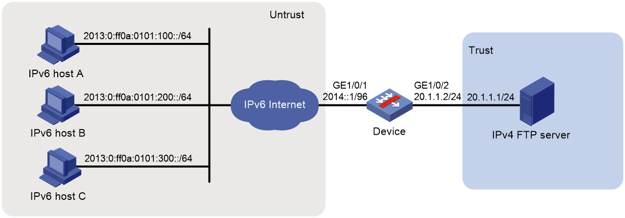
Procedure
1. Assign IP addresses to interfaces:
# Assign an IP address to interface GigabitEthernet 1/0/1.
<Device> system-view
[Device] interface gigabitethernet 1/0/1
[Device-GigabitEthernet1/0/1] ip address 10.1.1.4 24
[Device-GigabitEthernet1/0/1] quit
# Assign IP addresses to other interfaces in the same way. (Details not shown.)
2. Add interfaces to security zones.
[Device] security-zone name trust
[Device-security-zone-Trust] import interface gigabitethernet 1/0/2
[Device-security-zone-Trust] quit
[Device] security-zone name untrust
[Device-security-zone-Untrust] import interface gigabitethernet 1/0/1
[Device-security-zone-Untrust] quit
3. Configure security policies:
# In the IPv6 security policy, configure a rule named aftlocalin to allow the device to perform AFT on the IPv6 host traffic destined for the IPv4 server.
[Device] security-policy ipv6
[Device-security-policy-ipv6] rule name aftlocalin
[Device-security-policy-ipv6-1-aftlocalin] source-zone untrust
[Device-security-policy-ipv6-1-aftlocalin] destination-zone local
[Device-security-policy-ipv6-1-aftlocalin] destination-ip-host 2012::1
[Device-security-policy-ipv6-1-aftlocalin] action pass
[Device-security-policy-ipv6-1-aftlocalin] quit
[Device-security-policy-ipv6] quit
# In the IPv4 security policy, configure a rule named aftlocalout to allow the device to forward the AFT-translated packets to the IPv4 server.
[Device] security-policy ip
[Device-security-policy-ip] rule name aftlocalout
[Device-security-policy-ip-1-aftlocalout] source-zone local
[Device-security-policy-ip-1-aftlocalout] destination-zone trust
[Device-security-policy-ip-1-aftlocalout] source-ip-host 30.1.1.1
[Device-security-policy-ip-1-aftlocalout] source-ip-host 30.1.1.2
[Device-security-policy-ip-1-aftlocalout] destination-ip-host 20.1.1.1
[Device-security-policy-ip-1-aftlocalout] action pass
[Device-security-policy-ip-1-aftlocalout] quit
4. Configure AFT settings:
# Map source IPv4 address 20.1.1.1 to source IPv6 address 2012::1.
[Device] aft v4tov6 source 20.1.1.1 2012::1
# Configure address group 0, and add the address range from 30.1.1.1 to 30.1.1.2 to the group.
[Device] aft address-group 0
[Device-aft-address-group-0] address 30.1.1.1 30.1.1.2
[Device-aft-address-group-0] quit
# Configure IPv6 ACL 2000 to permit all IPv6 packets to pass through.
[Device] acl ipv6 basic 2000
[Device-acl-ipv6-basic-2000] rule permit
[Device-acl-ipv6-basic-2000] quit
# Configure the device to translate source addresses of IPv6 packets permitted by IPv6 ACL 2000 to IPv4 addresses in address group 0.
[Device] aft v6tov4 source acl ipv6 number 2000 address-group 0
# Enable AFT on the interfaces connected to the IPv6 Internet and IPv4 network, respectively.
[Device] interface gigabitethernet 1/0/1
[Device-GigabitEthernet1/0/1] aft enable
[Device-GigabitEthernet1/0/1] quit
[Device] interface gigabitethernet 1/0/2
[Device-GigabitEthernet1/0/2] aft enable
[Device-GigabitEthernet1/0/2] quit
Verifying the configuration
# Verify the connectivity between the IPv6 hosts and the IPv4 FTP server. For example, ping the IPv4 FTP server from IPv6 host A.
D:\>ping 2012::1
Pinging 2012::1 with 32 bytes of data:
Reply from 2012::1: time=3ms
Reply from 2012::1: time=3ms
Reply from 2012::1: time=3ms
Reply from 2012::1: time=3ms
# Display detailed information about IPv6 AFT sessions on the device.
[Device] display aft session ipv6 verbose
Initiator:
Source IP/port: 2013:0:FF0A:0101:0100::/1029
Destination IP/port: 2012::1/21
VPN instance/VLAN ID/Inline ID: -/-/-
Protocol: IPV6-ICMP(58)
Inbound interface: GigabitEthernet1/0/1
Source security zone: Untrust
Responder:
Source IP/port: 2012::1/21
Destination IP/port: 2013:0:FF0A:0101:0100::/1029
VPN instance/VLAN ID/Inline ID: -/-/-
Protocol: IPV6-ICMP(58)
Inbound interface: GigabitEthernet1/0/2
Source security zone: Local
State: ICMPV6_REPLY
Application: ICMP
Rule ID: -/-/-
Rule name:
Start time: 2014-03-13 09:07:30 TTL: 3582s
Initiator->Responder: 3 packets 184 bytes
Responder->Initiator: 2 packets 148 bytes
Total sessions found: 1
# Display detailed information about IPv4 AFT sessions on the device.
[Device] display aft session ipv4 verbose
Initiator:
Source IP/port: 30.1.1.1/11025
Destination IP/port: 20.1.1.1/21
DS-Lite tunnel peer: -
VPN instance/VLAN ID/Inline ID: -/-/-
Protocol: ICMP(1)
Inbound interface: GigabitEthernet1/0/1
Source security zone: Local
Responder:
Source IP/port: 20.1.1.1/21
Destination IP/port: 30.1.1.1/11025
DS-Lite tunnel peer: -
VPN instance/VLAN ID/Inline ID: -/-/-
Protocol: ICMP(1)
Inbound interface: GigabitEthernet1/0/2
Source security zone: Trust
State: ICMP_REPLY
Application: ICMP
Rule ID: 0
Rule name: aftlocalout
Start time: 2014-03-13 09:07:30 TTL: 3577s
Initiator->Responder: 3 packets 124 bytes
Responder->Initiator: 2 packets 108 bytes
Total sessions found: 1
