- Table of Contents
-
- 07-Layer 3—IP Services Configuration Guide
- 00-Preface
- 01-ARP configuration
- 02-IP addressing configuration
- 03-DHCP configuration
- 04-DNS configuration
- 05-NAT configuration
- 06-NAT66 configuration
- 07-IP forwarding basics configuration
- 08-Fast forwarding configuration
- 09-Multi-CPU packet distribution configuration
- 10-Adjacency table configuration
- 11-IRDP configuration
- 12-IP performance optimization configuration
- 13-UDP helper configuration
- 14-IPv6 basics configuration
- 15-DHCPv6 configuration
- 16-IPv6 fast forwarding configuration
- 17-AFT configuration
- 18-Tunneling configuration
- 19-GRE configuration
- 20-ADVPN configuration
- 21-WAAS configuration
- 22-Lighttpd service configuration
- 23-Web caching configuration
- 24-STUN configuration
- Related Documents
-
| Title | Size | Download |
|---|---|---|
| 07-IP forwarding basics configuration | 76.51 KB |
Contents
Configuring IP forwarding basic settings························································ 1
About FIB table······························································································································· 1
Enabling last hop holding················································································································ 1
Enabling last hop backup················································································································ 3
Enabling IPv4 packet forwarding on an interface with no IPv4 address configured······························ 3
Enabling IPv6 packet forwarding on an interface with no IPv6 address configured······························ 4
Display and maintenance commands for FIB table············································································ 4
Configuring load sharing··················································································· 6
About load sharing·························································································································· 6
Configuring load sharing mode········································································································ 6
Configuring IP forwarding basic settings
About FIB table
A device uses the FIB table to make packet forwarding decisions.
A device selects optimal routes from the routing table, and puts them into the FIB table. Each FIB entry specifies the next hop IP address and output interface for packets destined for a specific subnet or host.
For more information about the routing table, see Layer 3—IP Routing Configuration Guide.
Use the display fib command to display the FIB table. The following example displays the entire FIB table.
<Sysname> display fib
Route destination count: 4
Directly-connected host count: 4
Flag:
U:Useable G:Gateway H:Host B:Blackhole D:Dynamic S:Static
R:Relay F:FRR
Destination/Mask Nexthop Flag OutInterface/Token Label
10.2.0.0/16 10.2.1.1 U GE1/0/1 Null
10.2.1.1/32 127.0.0.1 UH InLoop0 Null
127.0.0.0/8 127.0.0.1 U InLoop0 Null
127.0.0.1/32 127.0.0.1 UH InLoop0 Null
A FIB entry includes the following items:
· Destination—Destination IP address.
· Mask—Network mask. The mask and the destination address identify the destination network. A logical AND operation between the destination address and the network mask yields the address of the destination network. For example, if the destination address is 192.168.1.40 and the mask 255.255.255.0, the address of the destination network is 192.168.1.0. A network mask includes a certain number of consecutive 1s. It can be expressed in dotted decimal format or by the number of the 1s.
· Nexthop—IP address of the next hop.
· Flag—Route flag.
· OutInterface—Output interface.
· Token—MPLS Label Switched Path index number.
· Label—Inner label.
Enabling last hop holding
About this task
Last hop holding implements symmetric routing.
When the interface enabled with this feature receives the first IP packet of a forward flow, this feature implements the following operations:
· Obtains the forward flow information and last hop information of the packet.
· Based on the obtained information, creates a fast forwarding entry for the return flow.
When packets of the return flow arrive at the device, the device forwards those packets according to the entry.
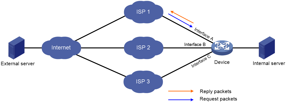
As is shown in Figure 1, when the external server sends a request to the internal server, the packet travels through ISP 1 to Interface A on the device. The last hop holding feature on the device ensures that the reply packet follows the same route as the request packet back to ISP 1. If last hop holding is disabled, the reply packet might be sent out of Interface B or Interface C to the external network.
Figure 1 Last hop holding application
Restrictions and guidelines
This feature relies on fast forwarding entries. If the MAC address of a last hop changes on an Ethernet link, this feature can function correctly only after the fast forwarding entry is updated for the MAC address.
This feature is not applicable to an MPLS network.
In an IRF fabric, this feature is not supported for those packets that are forwarded between member devices.
This feature is not applicable to asymmetric-path traffic forwarding in an RBM-based hot backup system. For more information about RBM-based hot backup, see high availability group configuration in High Availability Configuration Guide.
On a device that supports deployment of multiple security service modules, this feature does not take effect on the external traffic destined for that device.
Procedure
1. Enter system view.
system-view
2. Enter Layer 3 Ethernet interface view or subinterface view.
interface interface-type { interface-number | interface-number.subnumber }
3. Enable last hop holding.
ip last-hop hold
By default, last hop holding is disabled.
Enabling last hop backup
About this task
This feature enables the system to transmit the forward flow and return flow between the local device and a peer device over the same path in an IRF fabric.
With this feature configured, the IRF master device performs the following operations when receiving the first IP packet of a forward flow on an interface enabled with last hop holding:
1. Saves the last hop information of the packet.
2. Synchronizes the last hop information to subordinate devices in the IRF fabric.
The last hop information can be used for guiding the return flow when the flow arrives at the master device or is forwarded through a subordinate device.
This feature takes effect only when the session synchronization is enabled by using the session synchronization enable command. For more information about this command, see Security Command Reference.
This feature is also applicable to multi-module devices enabled with service backup. If this feature is enabled on such a device, a device module performs the following operations when receiving the first IP packet of a forward flow on an interface enabled with last hop holding:
1. Saves the last hop information of the packet.
2. Synchronizes the last hop information to other modules in the device.
The last hop information can be used for guiding the backward flow when the flow arrives at one of these modules.
For this feature to take effect on a multi-module device, you must also enable session flow redirection by using the session flow-redirect enable command. For more information about the session flow-redirect enable command, see Security Command Reference.
Support for this feature varies by device model. For more information, see the command reference.
Procedure
1. Enter system view.
system-view
2. Enable last hop backup.
last-hop backup enable
By default, last hop backup is enabled.
Enabling IPv4 packet forwarding on an interface with no IPv4 address configured
About this task
On a device that supports both IPv4 and IPv6, the next hop of an IPv4 packet might be an IPv4 address or an IPv6 address. If the output interface has no IPv4 address configured, the interface cannot forward the IPv4 packet. To solve this problem, enable this feature on the interface. This feature allows the interface to forward IPv4 packets even though the interface has no IPv4 address configured.
Restrictions and guidelines
You can configure this feature in any view in which an IPv4 address can be configured.
Hardware and feature compatibility
Support for this feature varies by device model. For more information, see the command reference.
Procedure
1. Enter system view.
system-view
2. Enter interface view.
interface interface-type interface-number
3. Enable IPv4 packet forwarding on an interface that has no IPv4 address configured.
ip forwarding
By default, IPv4 packet forwarding is disabled on an interface that has no IPv4 address configured.
Enabling IPv6 packet forwarding on an interface with no IPv6 address configured
About this task
On a device that supports both IPv4 and IPv6, the next hop of an IPv4 packet might be an IPv4 address or an IPv6 address. If the output interface has no IPv6 address configured, the interface cannot forward the IPv6 packet. To solve this problem, enable this feature on the interface. This feature allows the interface to forward IPv6 packets even though the interface has no IPv6 address configured.
Restrictions and guidelines
You can configure this feature in any view in which an IPv6 address can be configured.
Hardware and feature compatibility
Support for this feature varies by device model. For more information, see the command reference.
Procedure
1. Enter system view.
system-view
2. Enter interface view.
interface interface-type interface-number
3. Enable IPv6 packet forwarding on an interface that has no IPv6 address configured.
ipv6 forwarding
By default, IPv6 packet forwarding is disabled on an interface that has no IPv4 address configured.
Display and maintenance commands for FIB table
Execute display commands in any view.
Support for the topology topology-name option varies by device model. For more information, see the command reference.
|
Task |
Command |
|
Display FIB entries. |
display fib [ topology topology-name | vpn-instance vpn-instance-name ] [ ip-address [ mask | mask-length ] ] |
Configuring load sharing
About load sharing
If a routing protocol finds multiple equal-cost best routes to the same destination, the device forwards packets over the equal-cost routes to implement load sharing.
Configuring load sharing mode
About this task
In the per-flow load sharing mode, the device forwards flows over equal-cost routes. Packets of one flow travel along the same routes. You can configure the device to identify a flow based on the following criteria: source IP address, destination IP address, source port number, destination port number, IP protocol number, and ingress port.
Restrictions and guidelines
Per-packet load sharing does not take effect on packets that are fast forwarded. It takes effect only on those packets that are delivered to the CPU. For more information about configuring load balancing for fast forwarding, see fast forwarding configuration in Layer 3—IP Services Configuration Guide.
Procedure
1. Enter system view.
system-view
2. Configure load sharing.
ip load-sharing mode { per-flow [ dest-ip | dest-port | ip-pro | src-ip | src-port ] * | per-packet } global
ip load-sharing mode { per-flow [ dest-ip | dest-port | ip-pro | src-ip | src-port ] * | per-packet } { global | slot slot-number }
By default, the device performs per-flow load sharing.
