- Table of Contents
-
- 07-Layer 3—IP Services Configuration Guide
- 00-Preface
- 01-ARP configuration
- 02-IP addressing configuration
- 03-DHCP configuration
- 04-DNS configuration
- 05-NAT configuration
- 06-NAT66 configuration
- 07-IP forwarding basics configuration
- 08-Fast forwarding configuration
- 09-Multi-CPU packet distribution configuration
- 10-Adjacency table configuration
- 11-IRDP configuration
- 12-IP performance optimization configuration
- 13-UDP helper configuration
- 14-IPv6 basics configuration
- 15-DHCPv6 configuration
- 16-IPv6 fast forwarding configuration
- 17-AFT configuration
- 18-Tunneling configuration
- 19-GRE configuration
- 20-ADVPN configuration
- 21-WAAS configuration
- 22-Lighttpd service configuration
- 23-Web caching configuration
- 24-STUN configuration
- Related Documents
-
| Title | Size | Download |
|---|---|---|
| 24-STUN configuration | 248.96 KB |
Contents
STUN server deployment in private networks
Restrictions and guidelines: STUN configuration
Display and maintenance commands for STUN
Example: Configure STUN for SDWAN
Configuring STUN
About STUN
Session Traversal Utilities for NAT (STUN) is a protocol that serves as a tool for other protocols in dealing with NAT traversal. STUN can determine the existence of a NAT device in the network and determine the IP address and port allocated by the NAT device to an endpoint. STUN runs over UDP and uses port 3478 by default.
Basic concepts
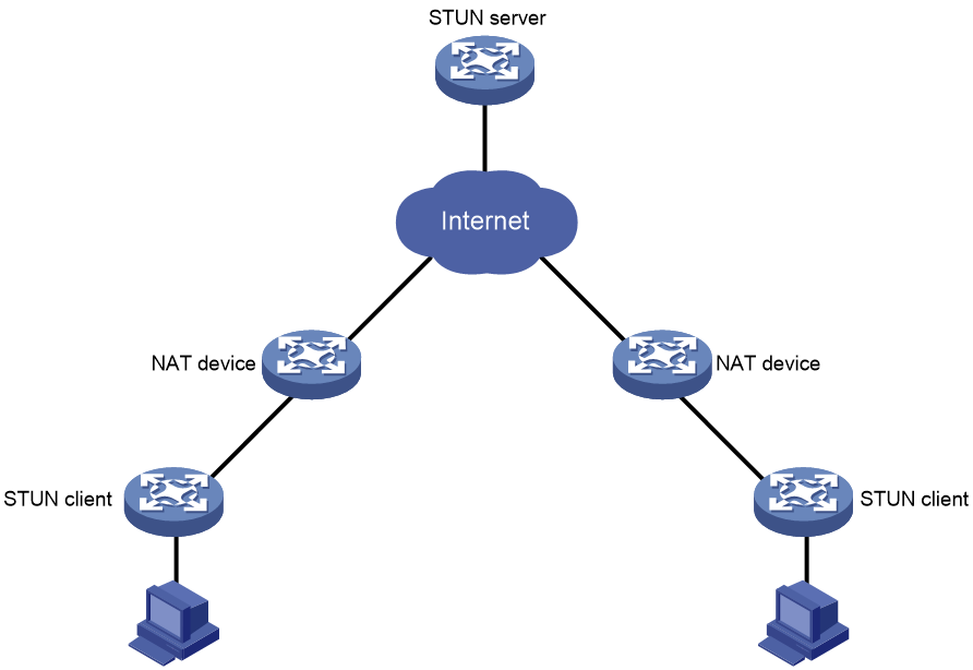
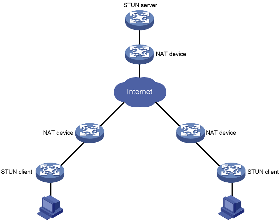
As shown in Figure 1, STUN uses a client-server model that consists of a STUN client and a STUN server.
· STUN client—An entity that sends STUN requests and receives STUN responses.
· STUN server—An entity that receives STUN requests and sends STUN responses. A STUN server typically resides on the public network.
The STUN server and STUN client exchange STUN packets (Binding requests and Binding responses) to detect the IP address and port number assigned by a NAT device and the NAT type.
NAT mapping and filtering
In STUN, NAT mapping and NAT filtering are used to determine the type of NAT and therefore determine whether STUN works correctly. The related concepts are described as follows:
· Endpoint—A combination of an IP address and a port number. For example, Endpoint (X:x) indicates that the IP address and port number are X and x, respectively.
· NAT mapping—Maps an internal IP address and port number to an external IP address and port number for packets from the internal network to the external network. When an internal endpoint opens an outgoing session through a NAT device, the NAT device establishes a mapping between the internal IP address and port number and an external IP address and port number. Then, the NAT device forwards the packet based on the mapping.
· NAT filtering—Filters out packets from the external network to the internal network. To protect the internal network from attacks, the NAT device will discard attack packets and forward normal packets.
NAT mapping types
The following NAT mapping types are supported:
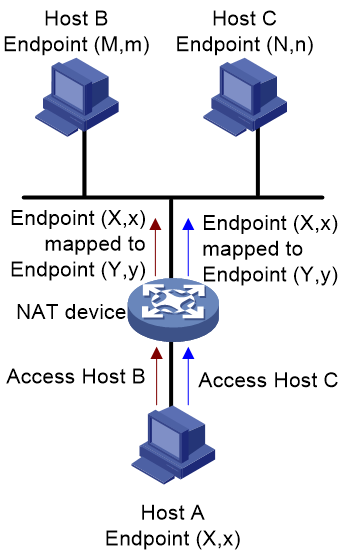
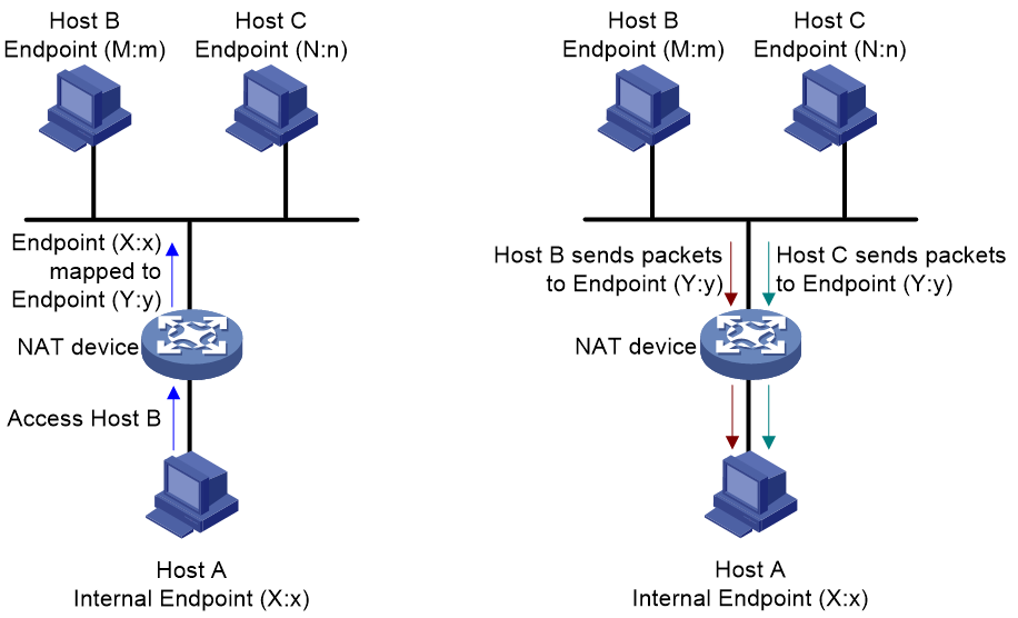
· Endpoint-independent mapping (EIM)—The NAT device uses the same mapping for all packets sent from the same internal IP address and port number to any external IP address and port number. As shown in Figure 2, Endpoint (X:x) in the internal network is always mapped to Endpoint (Y:y) in the external network.
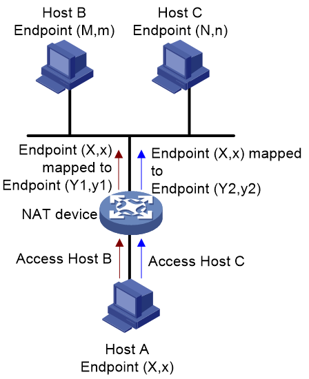
· Address-dependent mapping (ADM)—The NAT device uses the same mapping for all packets sent from the same internal IP address and port number to the same external IP address, regardless of the external port number. As shown in Figure 3, Endpoint (X:x) in the internal network is mapped to Endpoint (Y1:y1) in the external network when it accesses Host B. Endpoint (X:x) in the internal network is mapped to Endpoint (Y2:y2) in the external network when it accesses Host C. Y1:y1 equals Y2:y2 as long as M equals N.
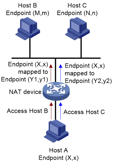
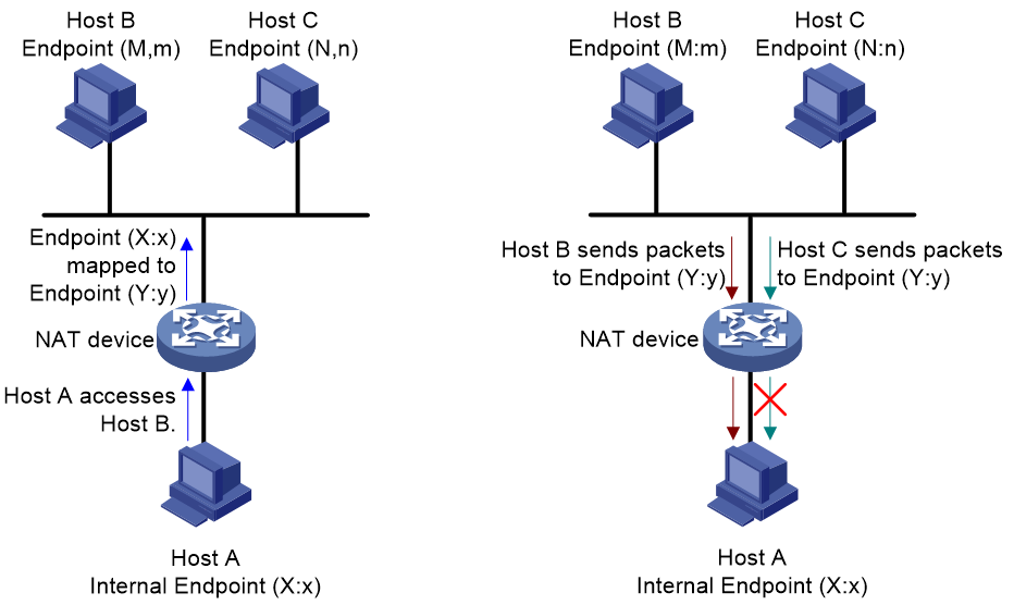
· Address and port-dependent mapping (APDM)—The NAT device uses the same mapping for all packets sent from the same internal IP address and port number to the same external IP address and port number. As shown in Figure 4, Endpoint (X:x) in the internal network is mapped to Endpoint (Y1:y1) in the external network when it accesses Host B. Endpoint (X:x) in the internal network is mapped to Endpoint (Y2:y2) in the external network when it accesses Host C. Y1:y1 equals Y2:y2 if M equals N and m equals n.
NAT filtering methods
The following NAT filtering types are supported:
· Endpoint-independent filtering (EIF)—As shown in Figure 5, the NAT device filters out only packets not destined to the internal IP address and port number (Endpoint (X:x), regardless of the external IP address and port source. The NAT device forwards any packets destined to X:x.
· Address-dependent filtering (ADF)—As shown in Figure 6, the NAT device filters out packets not destined to the internal address X:x. Additionally, the NAT device will filter out packets from Y:y destined for the internal endpoint X:x if X:x has not sent packets to Y:any port previously (independently of the port used by Y).
· Address and port-dependent filtering (APDF)—As shown in Figure 7, the NAT device filters out packets not destined to the internal address X:x. Additionally, the NAT device will filter out packets from Y:y destined for the internal endpoint X:x if X:x has not sent packets to Y:y previously.

NAT types
A NAT type is a combination of a NAT mapping type and a NAT filtering method. The following NAT types are supported:
· Full cone NAT (EIM+EIF)—Maps all requests from the same internal IP address and port number (IP1:Port1) to the same external IP address and port number (IP:Port). Additionally, any external host can send a packet to the internal host by sending a packet to the mapped external address.
· Restricted cone NAT (EIM+ADF)—Maps all requests from the same internal IP address and port number (IP1:Port1) to the same external IP address and port number (IP:Port). Unlike a full cone NAT, an external host (with IP address X) can send a packet to the internal host only if the internal host had previously sent a packet to IP address X.
· Port restricted cone NAT (EIM+APDF)—Maps all requests from the same internal IP address and port number (IP1:Port1) to the same external IP address and port number (IP:Port). Unlike a restricted cone NAT, an external host (with IP address and port number IP2:Port2) can send a packet to the internal host only if the internal host had previously sent a packet to IP address and port number IP2:Port2.
· Symmetric NAT (APDM+APDF)—Maps all requests from the same internal IP address and port number (IP1:Port1), to a specific destination IP address and port number, to the same external IP address and port number. If the same host sends a packet with the same source address and port, but to a different destination, a different mapping is used. Additionally, only the external host that receives a packet can send a UDP packet back to the internal host.
Application scenarios
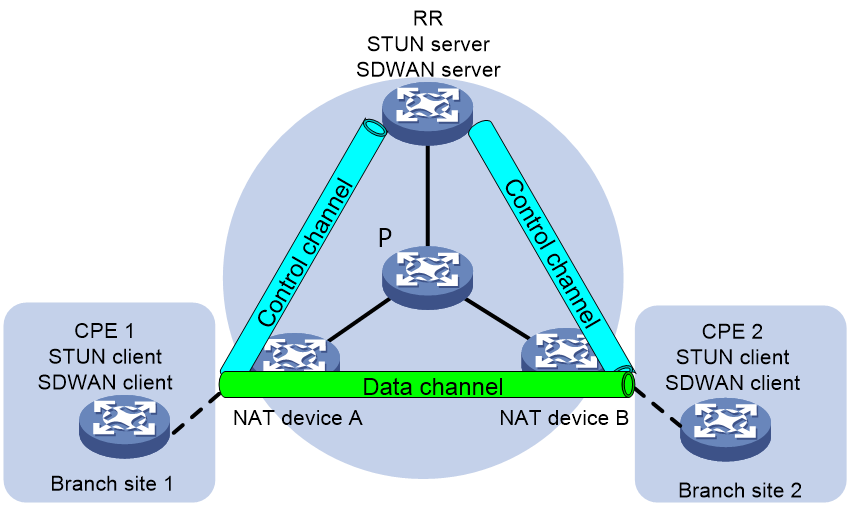
As shown in Figure 8, users at branch sites use private IP addresses so as to conserve IP address resources. After NAT devices translate the private IP addresses to public IP addresses, users at one branch site can access the headquarters.
IP addresses of the packets sent by a CPE will change after the packets pass through a NAT device. If the CPE cannot obtain its public IP address translated after NAT, it cannot establish a data channel with the other CPE. To resolve this issue, configure Session Traversal Utilities for NAT (STUN) in the SDWAN network. Typically, use CPEs as STUN clients and use the RR as the STUN server. The clients exchange packets with the server to identify whether NAT devices exist in the SDWAN network. If NAT devices exist, the clients obtain their public IP addresses and port numbers translated after NAT.
After a CPE (STUN client) obtains its public IP address and port number translated after NAT, it uses this public IP address to establish a data channel with the other CPE.
For more information about SDWAN tunnel establishment with NAT traversal, see SDWAN Configuration Guide.
Figure 8 SDWAN tunnel establishment with NAT traversal
STUN packet structure
STUN uses UDP as the transport protocol. Figure 9 shows the format of a STUN packet.
Figure 9 STUN packet structure
![]()
As shown in Figure 10, a STUN message starts with a 20-byte STUN header followed by zero or more STUN attributes.
Figure 10 STUN message structure

As shown in Figure 11, a STUN message starts with a 20-byte STUN header followed by zero or more STUN attributes.
Figure 11 STUN message structure
STUN header
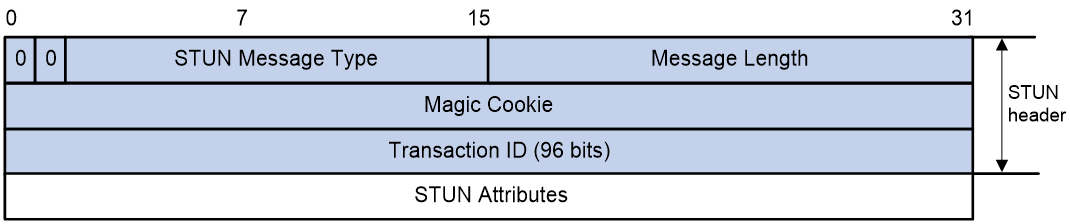
Figure 12 shows the STUN header structure.
Figure 12 STUN header structure
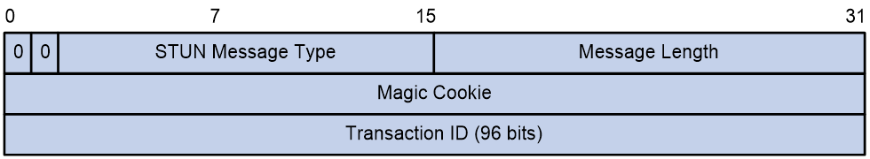
A STUN header contains the following fields:
· STUN Message Type—14-bit long and can only be Binding request or Binding response.
· Message Length—16-bit long. The message length does not include the STUN header.
· Magic Cookie—Contains the fixed value 0x2112A442. This field allows a server to detect if the client will understand certain attributes. In addition, it aids in distinguishing STUN packets from packets of other protocols when STUN is multiplexed with those other protocols on the same port.
· Transaction ID—Used to uniquely identify STUN transactions. The transaction ID is chosen by the STUN client for the request and echoed by the server in the response.
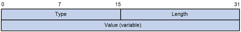
STUN attribute
Each STUN attribute is TLV (Type-Length-Value) encoded, with a 16-bit type, 16-bit length, and value.
Figure 13 Format of STUN attributes
The following are common STUN attributes:
· CHANGE-REQUEST—Carried in Binding requests. This attribute is used by the STUN client to request that the STUN server use a different address or port number when sending the response.
· MAPPED-ADDRESS—Carried in Binding responses. This attribute indicates the mapped IP address and port number of the client.
· XOR-MAPPED-ADDRESS—Carried in Binding responses. This field is identical to the MAPPED-ADDRESS attribute, except that the reflexive transport address is obfuscated through the XOR function.
· RESPONSE-ORIGIN—Carried in Binding responses. This attribute indicates the IP address and port number of the STUN server.
· OTHER-ADDRESS—Carried in Binding responses. This attribute indicates the alternate IP address and port number of the STUN server. Suppose the IP address and port number of the STUN server is Y1:YP1, and the alternate IP address and port number of the STUN server is Y2:YP2. Da represents the destination IP address in Binding requests sent by the STUN client, Dp represents the destination port number in Binding requests sent by the STUN client. If Da is Y1, the IP address in the OTHER-ADDRESS attribute is Y2. If Da is Y2, the IP address in the OTHER-ADDRESS attribute is Y1. If Dp is YP1, the port number in the OTHER-ADDRESS attribute is YP2. If Dp is YP2, the port number in the OTHER-ADDRESS attribute is YP1.
When the STUN client requests that the server use a different address or port number when sending the response:
¡ Using a different address—If the destination IP address of the Binding request is Y1, the alternate IP address is Y2, and vice versa. The STUN server uses the alternate IP address to send a response.
¡ Using a different port number—If the destination port number of the Binding request is YP1, the alternate port number is YP2, and vice versa. The STUN server uses the alternate port number to send a response.
If no alternate IP address is specified for a STUN server, the STUN server does not carry the OTHER-ADDRESS attribute in Binding responses. In this case, the STUN client cannot determine the NAT type.
How STUN works
The STUN client and STUN server exchange STUN packets to detect the NAT mapping type and NAT filtering method, therefore determining the NAT type.
NAT mapping type detection
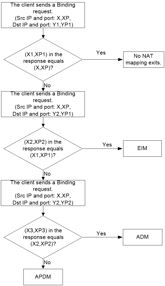
Suppose the IP address and port number of the STUN server is Y1:YP1, and the alternate IP address and port number of the STUN server is Y2:YP2. The IP address and port number of the STUN client is X:XP.
Figure 14 shows the process of NAT mapping type detection.
1. The STUN client sends a Binding request with source IP address and port number Endpoint (X:XP) to Endpoint (Y1:YP1) of the STUN server. The STUN server uses Endpoint (Y1:YP1) to send a Binding response to the STUN client. The Binding response includes the mapped Endpoint (X1:XP1) and another Endpoint (Y2:YP2) of the STUN server.
2. After receiving the Binding response, the STUN client checks whether Endpoint (X1:XP1) equals Endpoint (X:XP).
¡ If yes, the client considers that no mapping exists.
¡ If not, the client detects the mapping type as described in step 3.
3. The STUN client uses Endpoint (X:XP) to send a Binding request to Endpoint (Y2,YP1) of the STUN server. The STUN server uses Endpoint (Y2,YP1) to send a Binding response to the STUN client. The Binding response includes the mapped Endpoint (X2:XP2) of the STUN client.
4. After receiving the Binding response, the STUN client checks whether Endpoint (X2:XP2) equals Endpoint (X1:XP1) in step 1.
¡ If yes, the client considers that the mapping type is EIM.
¡ If not, the client detects the mapping type as described in step 5.
5. The STUN client uses Endpoint (X:XP) to send a Binding request to Endpoint (Y2:YP2) of the STUN server. The STUN server uses Endpoint (Y2:YP2) to send a Binding response to the STUN client. The Binding response includes the mapped Endpoint (X3:XP3) of the STUN client.
6. After receiving the Binding response, the STUN client checks whether Endpoint (X3:XP3) equals Endpoint (X2:XP2) in step 3.
¡ If yes, the client considers that the mapping type is ADM.
¡ If not, the client considers that the mapping type is APDM.
Figure 14 Process of NAT mapping type detection
NAT filtering method detection
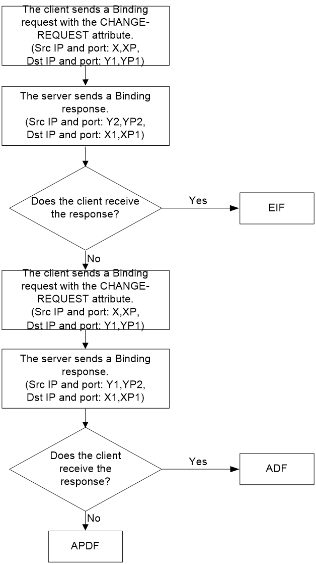
Suppose the IP address and port number of the STUN server is Y1:YP1, and the alternate IP address and port number of the STUN server is Y2:YP2. The IP address and port number of the STUN client is X:XP.
Figure 15 shows the process of NAT filtering method detection.
1. The STUN client sends a Binding request with source IP address and port number Endpoint (X:XP) to Endpoint (Y1:YP1) of the STUN server. The request includes the CHANGE-REQUEST attribute, which requests that the server use a different IP address and port number when sending the response. The OTHER-ADDRESS attribute in the response indicates that the alternate IP address and port number of the STUN server is Endpoint (Y2:YP2). The STUN server uses Endpoint (Y2:YP2) to send a Binding response to the STUN client.
2. If the client receives the Binding response, it considers that the mapping type is EIM.
3. If the client fails to receive the Binding response, it continues to detect the mapping type as described in step 3.
4. The client uses Endpoint (X:XP) to send a Binding request to Endpoint (Y1:YP1) of the STUN server. The request includes the CHANGE-REQUEST attribute, which requests that the server use a different IP address and port number when sending the response. The OTHER-ADDRESS attribute in the response indicates that the alternate port number of the STUN server is YP2. The STUN server uses Endpoint (Y1,YP2) to send a Binding response to the client.
5. If the client receives the Binding response, it considers that the mapping type is ADF.
6. If the client fails to receive the Binding response, it considers that the mapping type is APDF.
Figure 15 Process of NAT filtering method detection
STUN server deployment in private networks
Typically, a STUN server is deployed in a public network. After receiving a Binding request from a STUN client, a STUN server sends a Binding response with the IP address in its payload as the public address of the STUN server. If a STUN server is deployed in a private network, the IP address in the Binding response is the private address of the STUN server. When receiving a subsequent Binding request, the STUN server-side NAT device will not translate the private address in the request to a public address. For STUN to work correctly in this case, perform the following tasks:
· On the STUN server, specify the IP address and alternate IP address of the STUN server after NAT.
· Use one-to-one NAT mapping rule on the NAT device.
In this manner, STUN clients will not sense the private address of the STUN server and uses the public address of the STUN server for communication. The STUN server will still use its public address in Binding responses.
Figure 16 STUN server deployment in a private network
Client retransmissions
STUN runs over UDP, and STUN packets might be discarded during transit. Reliability of STUN request/response transactions is accomplished through retransmissions of the STUN request by the client as follows:
1. The client retransmits a request at an interval if failing to receive a response.
2. The client stops retransmissions until receiving a response or having retransmitted the maximum number of requests.
3. If the client fails to receive a response after the last request is sent, it considers the transaction to have failed.
Protocols and standards
· RFC 3489, STUN - Simple Traversal of User Datagram Protocol (UDP) Through Network Address Translators (NATs)
· RFC 4787, Network Address Translation (NAT) Behavioral Requirements for Unicast UDP
· RFC 5389, Session Traversal Utilities for NAT (STUN)
· RFC 5780, NAT Behavior Discovery Using Session Traversal Utilities for NAT (STUN)
Restrictions and guidelines: STUN configuration
For STUN detection to work correctly, make sure the STUN client can reach both the IP address and alternate IP address of the STUN server.
STUN tasks at a glance
To configure STUN, perform the following tasks:
Prerequisites for STUN
STUN is used to address NAT traversal in an SDWAN network, and the STUN detection results are transmitted in an SDWAN tunnel. Before you configure STUN, you must configure SDWAN (see SDWAN Configuration Guide).
Configure the STUN server
1. Enter system view.
system-view
2. Enable the STUN server and configure an IP address and port number for the STUN server.
stun server ip ip-address [ port port-number ] [ alternative-ip ip-address [ alternative-port port-number ] ] [ vpn-instance vpn-instance-name ] [ global-ip global-ip-address [ global-port port-number ] [ global-alternative-ip ip-address [ global-alternative-port port-number ] ] ]
By default, the STUN server is disabled.
Configure the STUN client
1. Enter system view.
system-view
2. Enter tunnel interface view.
interface tunnel number [ mode { advpn { gre | udp } [ ipv6 ] | ds-lite-aftr | eogre | eogre-udp | evi [ ipv6 ] | gre [ ipv6 ] | gre-p2mp [ ipv6 ] | ipsec [ ipv6 ] | ipv4-ipv4 | ipv4-ipv6 | ipv6 | ipv6-ipv4 [ 6rd | 6to4 | auto-tunnel | isatap ] | ipv6-ipv6 | mgre | mpls-te | nve | nvgre | sdwan udp | sr ipv6 |{ vxlan | vxlan-dci } [ ipv6 ] } ]
For more information about this command, see tunneling commands in Layer 3—IP Services Configuration Guide.
3. Enable the STUN client on the interface and specify the IP address and port number of the STUN server.
stun client destination-ip ip-address [ destination-port port-number ] [ out-interface interface-type interface-number ]
By default, the STUN client is disabled.
Display and maintenance commands for STUN
Execute the display commands in any view and the reset commands in user view.
|
Task |
Command |
|
Display packet statistics on the STUN client. |
display stun client info |
|
Display packet statistics on the STUN server. |
display stun server packet-statistics |
|
Clear packet statistics on the STUN client. |
reset stun client statistics |
|
Clear packet statistics on the STUN server. |
reset stun server packet-statistics |
STUN configuration examples
Example: Configure STUN for SDWAN
See SDWAN configuration example in SDWAN Configuration Guide. SDWAN uses STUN for NAT traversal.
