- Table of Contents
-
- H3C MSR Routers Configuration Examples(Web)-R6728-6W100
- 00-Preface
- 01-Web login Configuraiton Examples
- 02-Administrator Account Configuration Examples
- 03-Static Routing Configuration Examples
- 04-Cloud Connection Configuration Examples
- 05-Software Upgrade Examples
- 06-Port Mapping Configuration Examples
- 07-IPsec VPN Configuration Examples
- 08-L2TP VPN Configuration Examples
- 09-WLAN AC Configuration Examples
- Related Documents
-
| Title | Size | Download |
|---|---|---|
| 09-WLAN AC Configuration Examples | 347.86 KB |
Introduction
The following information provides an example of configuring the WLAN AC.
Prerequisites
This document is not restricted to specific software or hardware versions. Procedures and information in the examples might be slightly different depending on the software or hardware version of the device.
The configuration examples were created and verified in a lab environment, and all the devices were started with the factory default configuration. When you are working on a live network, make sure you understand the potential impact of every command on your network.
The following information is provided based on the assumption that you have basic knowledge of AC features.
Example: Configuring the AC
Network configuration
As shown in Figure 1, the router acts as the AC and connects to the AP through the Layer 2 switch. Configure the router to meet the following requirements:
· The client can access the router through the 2.4 GHz or 5 GHz wireless network provided by the AP, and can automatically obtain an IP address in VLAN 20.
· The AP can automatically obtain an IP address in VLAN 10.
· The Layer 2 switch supplies power to the AP through PoE.

Software versions used
This configuration example was created and verified on Release 6728P19 of the MSR830-10HI router.
Analysis
· Configure 2.4 GHz and 5 GHz service templates on the router for the AP to provide wireless services.
Table 1 Wireless parameters used in this example
|
Service template type |
SSID |
Working mode |
Working channel |
Maximum transmit power |
|
2.4 GHz |
service1 |
802.11g |
6 |
19 dm |
|
5 GHz |
service2 |
802.11ac |
157 |
19 dm |
· Configure VLAN 10 and VLAN 20 on the router. Use VLAN 10 for packet exchanges between the router and the AP, and use VLAN 20 for service template binding.
· Enable DHCP server on the router for the AP and the client to automatically obtain IP addresses through DHCP.
Restrictions and guidelines
· Set the working mode, working channel, and maximum transmit power based on the actual situation.
· Specify the two ports used for router and switch connection and the port that connects the switch to the AP as trunk ports. Assign the ports to the AP management VLAN and service VLAN, and specify the AP management VLAN as the default VLAN.
· You can create a manual AP or enable auto AP for the AP to come online. This example creates a manual AP. Use the serial ID labeled on the AP's rear panel to specify an AP.
Procedures
Configuring the router
Configuring VLAN 10
# Add VLAN 10, assign an IP address to VLAN-interface 10, and enable the DHCP service on the interface.
1. Log in to the Web interface of the router. From the navigation pane, select Network > LAN Settings.
2. Click Add.
3. In the LAN interface type field, select VLAN interface.
4. In the VLAN ID field, enter 10.
5. In the Interface IP address field, enter 192.168.10.1.
6. In the Subnet mask field, enter 255.255.255.0.
7. Select Enable DHCP.
8. Retain the default settings in the other fields, and then click Apply.
Figure 2 Configuring VLAN 10

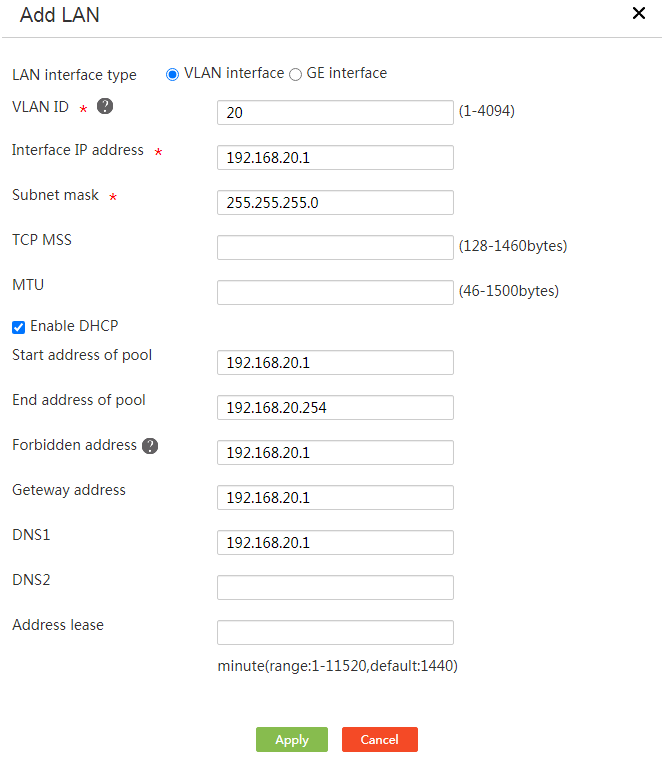
Configuring VLAN 20
# Add VLAN 20, assign an IP address to VLAN-interface 20, and enable the DHCP service on the interface.
1. From the navigation pane, select Network > LAN Settings.
2. Click Add.
3. In the LAN interface type field, select VLAN interface.
4. In the VLAN ID field, enter 20.
5. In the Interface IP address field, enter 192.168.20.1.
6. In the Subnet mask field, enter 255.255.255.0.
7. Select Enable DHCP.
8. Retain the default settings in the other fields, and then click Apply.
Figure 3 Configuring VLAN 20
Configuring interface GE1
# Assign GE1 to VLAN 10 and VLAN 20, and set the PVID to 10.
1. From the navigation pane, select Network > LAN Settings.
2. Click the VLAN Division tab.
3. Click the Edit icon in the Operation column for GE1.
4. In the PVID field, select 10.
5. Add VLAN 20 as a permitted VLAN.
6. Click Apply.
Figure 4 Assigning GE1 to VLAN 10 and VLAN 20

Configure the AC
# Create a manual AP.
1. From the navigation pane, select WLAN AC.
2. Select Quick Start > Add New AP.
3. Configure the AP as needed.
¡ Specify the AP name. In this example, the name is ap1.
¡ Select the AP model. In this example, the model is WA4320H.
¡ Specify the AP serial number. In this example, the serial number is 219801A0YG819BE005JC.
4. Retain the default settings in the other fields, and click Apply.
Figure 5 Adding an AP

# Configure the 2.4 GHz radio.
1. From the navigation pane, select Wireless Configuration > Radio Configuration.
2. Click the More icon for the Radios of all APs field.
3. Click the Edit icon for the 2.4 GHz radio.
4. Click Change Radio Mode.
a. Specify the radio type as 802.11g.
b. Specify the channel as 6.
c. Specify the maximum transmit power as 19.
5. Retain the default settings in the other fields, and click Apply.
Figure 6 Configuring the 2.4 GHz radio

# Configure the 5 GHz radio.
1. From the navigation pane, select Wireless Configuration > Radio Configuration.
2. Click the More icon for the Radios of all APs field.
3. Click the Edit icon for the 5 GHz radio type.
4. Click Change Radio Mode.
a. Specify the radio type as 802.11ac.
b. Specify the channel as 157.
c. Specify the maximum transmit power as 19.
5. Retain the default settings in the other fields, and click Apply.
Figure 7 Configuring the 5 GHz radio

# Configure the 2.4 GHz service template.
1. From the navigation pane, select Wireless Configuration > Wireless Networks.
2. Specify the service name as map1.
3. Specify the SSID as service1.
4. Enable the wireless service.
5. Specify the default VLAN ID as 20.
Figure 8 Configuring the 2.4 GHz service template

# Bind the 2.4 GHz service template to the 2.4 GHz radio.
1. On the wireless network adding page, click Apply and Configure Advanced Settings.
2. Click the Binding tab.
3. Select ap1 (Radio2 2.4G) and add the option to the selected box.
4. Click Apply.
Figure 9 Binding the 2.4 GHz service template to the 2.4 GHz radio

# Configure the 5 GHz service template.
1. From the navigation pane, select Wireless Configuration > Wireless Networks.
2. Specify the service name as map2.
3. Specify the SSID as service2.
4. Enable the wireless service.
5. Specify the default VLAN ID as 20.
Figure 10 Configuring the 5 GHz service template

# Bind the 5 GHz service template to the 5 GHz radio.
1. On the wireless network adding page, click Apply and Configure Advanced Settings.
2. Click the Binding tab.
3. Select ap1 (Radio1 5G) and add the option to the selected box.
4. Click Apply.
Figure 11 Binding the 5 GHz service template to the 5 GHz radio

Configuring the Layer 2 switch
# Configure VLANs and VLAN interfaces.
<L2 switch> system-view
[L2 switch] vlan 10
[L2 switch-vlan100] quit
[L2 switch] vlan 20
[L2 switch-vlan201] quit
[L2 switch] interface gigabitethernet 1/0/1
[L2 switch-GigabitEthernet1/0/1] port link-type trunk
[L2 switch-GigabitEthernet1/0/1] port trunk pvid vlan 10
[L2 switch-GigabitEthernet1/0/1] port trunk permit vlan 10 20
[L2 switch-GigabitEthernet1/0/1] quit
[L2 switch] interface gigabitethernet 1/0/2
[L2 switch-GigabitEthernet1/0/2] port link-type trunk
[L2 switch-GigabitEthernet1/0/2] port trunk pvid vlan 10
[L2 switch-GigabitEthernet1/0/2] port trunk permit vlan 10 20
[L2 switch-GigabitEthernet1/0/2] quit
[L2 switch]
# Enable PoE.
[L2 switch] interface gigabitethernet 1/0/2
[L2 switch-GigabitEthernet1/0/2] poe enable
[L2 switch-GigabitEthernet1/0/2] quit
Verifying the configuration
# Verify that the AP has established a tunnel with the AC and has entered Run state.
[Router]display wlan ap name ap1 verbose
AP name : ap1
AP ID : 1
AP group name : default-group
State : Run
Backup type : Master
Online time : 0 days 4 hours 7 minutes 27 seconds
System uptime : 0 days 4 hours 17 minutes 4 seconds
Model : WA4320H
Region code : CN
Region code lock : Disabled
Serial ID : 219801A0YG819BE005JC
MAC address : 9429-2f93-14c0
IP address : 192.168.0.4
UDP control port number : 25930
UDP data port number : 25930
H/W version : Ver.B
S/W version : R2439P01
Boot version : 7.21
USB state : Disabled
Power level : N/A
Power info : N/A
Description : Not configured
Priority : 4
Echo interval : 10 seconds
Echo count : 3 counts
…
# Verify that the client can access the 2.4 GHz network and the 5 GHz network. You can use the display wlan client verbose command to view the online client connections.
[Router]display wlan client verbose
Total number of clients: 2
MAC address : 424a-b9db-91bf
IPv4 address : 192.168.20.3
IPv6 address : N/A
Username : N/A
AID : 2
AP ID : 1
AP name : ap1
Radio ID : 2
SSID : service1
BSSID : 9429-2f93-14d0
VLAN ID : 20
Sleep count : 22
Wireless mode : 802.11g
Supported rates : 1, 2, 5.5, 6, 9, 11,
12, 18, 24, 36, 48, 54 Mbps
QoS mode : WMM
Listen interval : 20
RSSI : 54
Rx/Tx rate : 0/0 Mbps
Speed : N/A
Authentication method : Open system
Security mode : PRE-RSNA
AKM mode : Not configured
Cipher suite : N/A
User authentication mode : Bypass
WPA3 status : N/A
Authorization CAR : N/A
Authorization ACL ID : N/A
Authorization user profile : N/A
Roam status : N/A
Key derivation : N/A
PMF status : N/A
Forwarding policy name : Not configured
Online time : 0days 0hours 0minutes 6seconds
FT status : Inactive