- Table of Contents
- Related Documents
-
| Title | Size | Download |
|---|---|---|
| 07-Network | 1.63 MB |
Contents
Recommended VLAN configuration procedures
Recommended configuration procedure for assigning an access port to a VLAN
Recommended configuration procedure for assigning a trunk port to a VLAN
Recommended configuration procedure for assigning a hybrid port to a VLAN
Configuring the link type of a port
Security mode and normal mode of voice VLANs
Recommended voice VLAN configuration procedure
Configuring voice VLAN globally
Configuring voice VLAN on ports
Adding OUI addresses to the OUI list
Voice VLAN configuration examples
Configuring voice VLAN on a port in automatic voice VLAN assignment mode
Configuring a voice VLAN on a port in manual voice VLAN assignment mode
Configuring the MAC address table
How a MAC address entry is created
MAC address table-based frame forwarding
Displaying and configuring MAC address entries
Setting the aging time of MAC address entries
MAC address table configuration example
Implementation of MSTP on devices
Recommended MSTP configuration procedure
Displaying MSTP information of a port
Configuring link aggregation and LACP
Basic concepts of link aggregation
Load sharing mode of an aggregation group
Recommended link aggregation and LACP configuration procedures
Creating a link aggregation group
Displaying information of an aggregate interface
Displaying information of LACP-enabled ports
Link aggregation and LACP configuration example
Compatibility of LLDP with CDP
Recommended LLDP configuration procedure
Configuring LLDP settings on ports
Setting LLDP parameters for a single port
Configuring LLDP settings for ports in batch
Displaying LLDP information for a port
Displaying global LLDP information
Displaying LLDP information received from LLDP neighbors
LLDP basic settings configuration example
CDP-compatible LLDP configuration example
Overview
Ethernet is a network technology based on the CSMA/CD mechanism. As the medium is shared, collisions and excessive broadcasts are common on an Ethernet. To address the issue, virtual LAN (VLAN) was introduced to break a LAN down into separate VLANs. VLANs are isolated from each other at Layer 2. A VLAN is a bridging domain, and all broadcast traffic is contained within it, as shown in Figure 1.
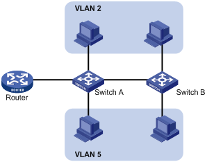
A VLAN is logically divided on an organizational basis rather than on a physical basis. For example, all workstations and servers used by a particular workgroup can be assigned to the same VLAN, regardless of their physical locations.
VLAN technology delivers the following benefits:
· Confines broadcast traffic within individual VLANs. This reduces bandwidth waste and improves network performance.
· Improves LAN security. By assigning user groups to different VLANs, you can isolate them at Layer 2. To enable communication between VLANs, routers or Layer 3 switches are required.
· Creates flexible virtual workgroup. As users from the same workgroup can be assigned to the same VLAN regardless of their physical locations, network construction and maintenance is much easier and more flexible.
VLAN fundamentals
To enable a network device to identify frames of different VLANs, a VLAN tag field is inserted into the data link layer encapsulation. The format of VLAN-tagged frames is defined in IEEE 802.1Q-1999.
In the header of a traditional Ethernet data frame, the field after the destination MAC address and the source MAC address is the Type field indicating the upper layer protocol type, as shown in Figure 2.
Figure 2 Traditional Ethernet frame format
![]()
IEEE 802.1Q inserts a four-byte VLAN tag after the DA&SA field, as shown in Figure 3.
Figure 3 Position and format of VLAN tag
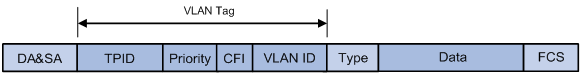
A VLAN tag comprises the following fields:
· Tag protocol identifier (TPID)—The 16-bit TPID field indicates whether the frame is VLAN-tagged and is 0x8100 by default.
· Priority—The 3-bit priority field indicates the 802.1p priority of the frame.
· Canonical format indicator (CFI)—The 1-bit CFI field specifies whether the MAC addresses are encapsulated in the standard format when packets are transmitted across different media. A value of 0 indicates that MAC addresses are encapsulated in the standard format. The value of 1 indicates that MAC addresses are encapsulated in a non-standard format. The value of the field is 0 by default.
· VLAN ID—The 12-bit VLAN ID field identifies the VLAN the frame belongs to. The VLAN ID range is 0 to 4095. As 0 and 4095 are reserved, a VLAN ID actually ranges from 1 to 4094.
A network device handles an incoming frame depending on whether the frame is VLAN tagged and the value of the VLAN tag, if any.
The Ethernet II encapsulation format is used in this section. In addition to the Ethernet II encapsulation format, Ethernet also supports other encapsulation formats, including 802.2 LLC, 802.2 SNAP, and 802.3 raw. The VLAN tag fields are added to frames encapsulated in these formats for VLAN identification.
When a frame carrying multiple VLAN tags passes through, the device processes the frame according to its outer VLAN tag, and transmits the inner tags as payload.
VLAN types
You can implement VLANs based on the following criteria:
· Port
· MAC address
· Protocol
· IP subnet
· Policy
· Other criteria
The Web interface is available only for port-based VLANs, and this chapter introduces only port-based VLANs.
Port-based VLAN
Port-based VLANs group VLAN members by port. A port forwards traffic for a VLAN only after it is assigned to the VLAN.
Port link type
You can configure the link type of a port as access, trunk, or hybrid. The link types use the following VLAN tag handling methods:
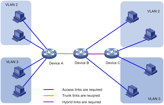
· Access port—An access port belongs to only one VLAN and sends traffic untagged. It is usually used to connect a terminal device unable to identify VLAN tagged-packets or when it is unnecessary to separate different VLAN members. As shown in Figure 4, Device A is connected to common PCs that cannot recognize VLAN tagged-packets, and you must configure Device A's ports that connect to the PCs as access ports.
· Trunk port—A trunk port can carry multiple VLANs to receive and send traffic for them. Except traffic from the port VLAN ID (PVID), traffic sent through a trunk port will be VLAN tagged. Usually, ports that connect network devices are configured as trunk ports. As shown in Figure 4, Device A and Device B need to transmit packets of VLAN 2 and VLAN 3, and you must configure the ports interconnecting Device A and Device B as trunk ports and assign them to VLAN 2 and VLAN 3.
· Hybrid port—A hybrid port allows traffic of some VLANs to pass through untagged and traffic of some other VLANs to pass through tagged. Usually, hybrid ports are configured to connect devices whose support for VLAN-tagged packets are uncertain. As shown in Figure 4, Device C connects to a small-sized LAN in which some PCs belong to VLAN 2 and other PCs belong to VLAN 3, and Device B is uncertain about whether Device C supports VLAN-tagged packets. Configure on Device B the port connecting to Device C as a hybrid port to allow packets of VLAN 2 and VLAN 3 to pass through untagged.
PVID
By default, VLAN 1 is the PVID for all ports. You can change the PVID for a port, as required.
Use the following guidelines when you configure the PVID on a port:
· An access port can join only one VLAN. The VLAN to which the access port belongs is the PVID of the port.
· A trunk or hybrid port can join multiple VLANs, and you can configure a PVID for the port.
· You can use a nonexistent VLAN as the PVID for a hybrid or trunk port, but not for an access port. After you delete the VLAN that an access port resides in, the PVID of the port changes to VLAN 1. However, deleting the VLAN specified as the PVID of a trunk or hybrid port does not affect the PVID setting on the port.
· Do not set the voice VLAN as the PVID of a port in automatic voice VLAN assignment mode. For information about voice VLAN, see "Configuring a voice VLAN."
· H3C recommends that you set the same PVID for local and remote ports.
· Make sure a port permits its PVID. Otherwise, when the port receives frames tagged with the PVID or untagged frames, the port drops these frames.
Frame handling methods
The following table shows how ports of different link types handle frames:
|
Actions |
Access |
Trunk |
Hybrid |
|
|
In the inbound direction for an untagged frame |
Tags the frame with the PVID tag. |
Checks whether the PVID is permitted on the port: · If yes, tags the frame with the PVID tag. · If not, drops the frame. |
||
|
In the inbound direction for a tagged frame |
· Receives the frame if its VLAN ID is the same as the PVID. · Drops the frame if its VLAN ID is different from the PVID. |
· Receives the frame if its VLAN is permitted on the port. · Drops the frame if its VLAN is not permitted on the port. |
||
|
In the outbound direction |
Removes the VLAN tag and sends the frame. |
· Removes the tag and sends the frame if the frame carries the PVID tag and the port belongs to the PVID. · Sends the frame without removing the tag if its VLAN is carried on the port, but is different from the PVID. |
Sends the frame if its VLAN is permitted on the port. The frame is sent with the VLAN tag removed or intact depending on your configuration with the port hybrid vlan command. This is true of the PVID. |
|
Configuration guidelines
When you configure VLANs, follow these guidelines:
· As the default VLAN, VLAN 1 can be neither created nor removed manually.
· You cannot manually create or remove VLANs reserved for special purposes.
· Dynamic VLANs cannot be removed on the page for removing VLANs.
Recommended VLAN configuration procedures
Recommended configuration procedure for assigning an access port to a VLAN
|
Step |
Remarks |
|
|
1. Creating VLANs. |
Required. Create one or multiple VLANs. |
|
|
Optional. Configure the link type of the port as access. By default, the link type of a port is access. |
||
|
Configure the PVID of the access port. |
Required. An access port has only one untagged VLAN and the untagged VLAN is its PVID. The three operations produce the same result, and the latest operation takes effect. By default, an access port is an untagged member of VLAN 1. |
|
|
4. Configuring the access ports as untagged members of a VLAN: a. Selecting a VLAN b. Modifying a VLAN |
N/A |
|
|
5. Modifying a port. |
Configure the untagged VLAN of the port. |
|
Recommended configuration procedure for assigning a trunk port to a VLAN
|
Step |
Remarks |
|
|
1. Creating VLANs. |
Required. Create one or multiple VLANs. |
|
|
Optional. Configure the link type of the port as trunk. To configure a hybrid port as a trunk port, first configure it as an access port. By default, the link type of a port is access. |
||
|
Configure the PVID of the trunk port. |
Required. A trunk port has only one untagged VLAN and the untagged VLAN is its PVID. The three operations produce the same result, and the latest operation takes effect. By default, the untagged VLAN of a trunk port is VLAN 1. When you change the untagged VLAN (PVID) of a trunk port, the former untagged VLAN automatically becomes a tagged VLAN of the trunk port. |
|
|
4. Configure the trunk port as an untagged member of the specified VLANs: a. Selecting a VLAN b. Modifying a VLAN |
N/A |
|
|
5. Modifying a port. |
Configure the untagged VLAN of the trunk port. |
|
|
6. Configure the trunk port as a tagged member of the specified VLANs: a. Selecting a VLAN b. Modifying a VLAN |
N/A |
Required. A trunk port can have multiple tagged VLANs. You can repeat these steps to configure multiple tagged VLANs for the trunk port. |
|
7. Modifying a port. |
Configure the tagged VLAN of the trunk port. |
|
Recommended configuration procedure for assigning a hybrid port to a VLAN
|
Step |
Remarks |
|
|
1. Creating VLANs. |
Required. Create one or multiple VLANs. |
|
|
Optional. Configure the link type of the port as hybrid. To configure a trunk port as a hybrid port, first configure it as an access port. If you configure multiple untagged VLANs for a trunk port at the same time, the trunk port automatically becomes a hybrid port. By default, the link type of a port is access. |
||
|
Optional. Configure the PVID of the hybrid port. By default, the PVID of a hybrid port is VLAN 1. |
||
|
4. Configure the hybrid port as an untagged member of the specified VLANs: a. Selecting a VLAN b. Modifying a VLAN |
N/A |
Required. A hybrid port can have multiple untagged VLANs. Repeat these steps to configure multiple untagged VLANs for a hybrid port. By default, the untagged VLAN of a hybrid port is VLAN 1. |
|
5. Modifying a port. |
Configure the untagged VLAN of the hybrid port. |
|
|
6. Configure the hybrid port as a tagged member of the specified VLAN: a. Selecting a VLAN b. Modifying a VLAN |
N/A |
Required. A hybrid port can have multiple tagged VLANs. You can repeat these steps to configure multiple tagged VLANs for the hybrid port. |
|
7. Modifying a port. |
Configure the tagged VLAN of the hybrid port. |
|
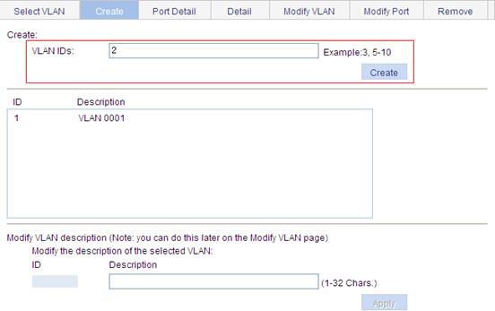
Creating VLANs
1. Select Network > VLAN from the navigation tree.
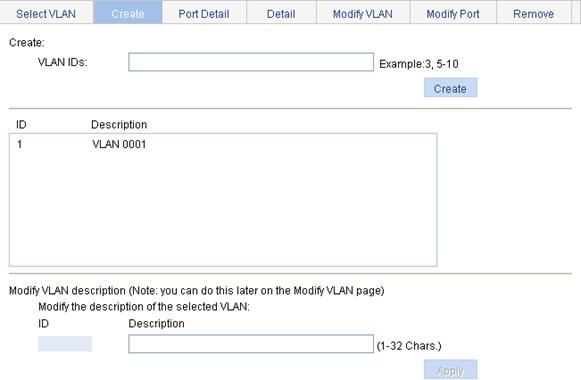
2. Click Create to enter the page for creating VLANs.
3. Enter the VLAN IDs, a VLAN ID range, or both.
4. Click Create.
Figure 5 Creating VLANs
|
Item |
Description |
|
VLAN IDs |
IDs of the VLANs to be created. |
|
Modify the description of the selected VLAN |
·
ID—Select the ID of the VLAN whose description string is to be
modified. ·
Description—Set the description string of the selected VLAN. |
Configuring the link type of a port
You can also configure the link type of a port on the Setup tab of Device > Port Management. For more information, see "Managing ports."
To configure the link type of a port:
1. Select Network > VLAN from the navigation tree.
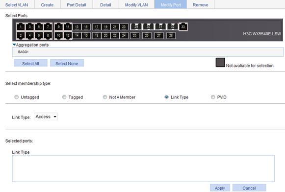
2. Click the Modify Port tab.
3. Select the port that you want to configure on the chassis front panel.
4. Select the Link Type option.
5. Set the link type, which can be access, hybrid, or trunk.
6. Click Apply.
A progress dialog box appears.
7. Click Close on the progress dialog box when the dialog box prompts that the configuration succeeds.
Figure 6 Modifying ports
Setting the PVID for a port
You can also configure the PVID of a port on the Setup tab of Device > Port Management. For more information, see "Managing ports."
To set the PVID for a port:
1. Select Network > VLAN from the navigation tree.
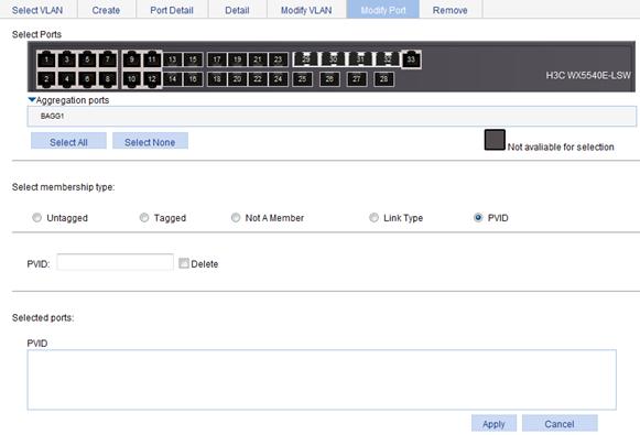
2. Click the Modify Port tab.
3. Select the port that you want to configure on the chassis front panel.
4. Select the PVID option.
The option allows you to modify the PVID of the port.
5. Set a PVID for the port. By selecting the Delete box, you can restore the PVID of the port to the default, which is VLAN 1.
The PVID of an access port must be an existing VLAN.
6. Click Apply.
A progress dialog box appears.
7. Click Close on the progress dialog box when the dialog box prompts that the configuration succeeds.
Figure 7 Modifying the PVID for a port
Selecting a VLAN
1. Select Network > VLAN from the navigation tree.
The Select VLAN tab is displayed by default for you to select VLANs.
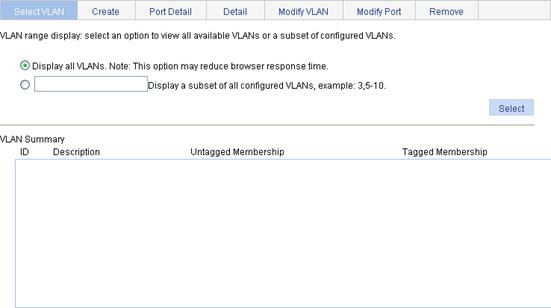
2. Select the Display all VLANs option to display all VLANs, or select the Display a subnet of all configured VLANs option to enter the VLAN IDs to be displayed.
3. Click Select.
Modifying a VLAN
1. Select Network > VLAN from the navigation tree.
2. Click Modify VLAN to enter the page for modifying a VLAN.
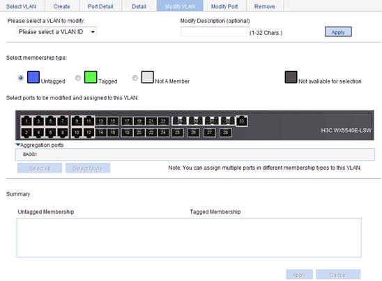
3. Modify the member ports of a VLAN as described in Table 2.
4. Click Apply.
A progress dialog box appears.
5. Click Close on the progress dialog box when the dialog box prompts that the configuration succeeds.
|
Item |
Description |
|
Please select a VLAN to modify |
Select the VLAN to be modified. The VLANs available for selection are existing VLANs selected on the page for selecting VLANs. |
|
Modify Description |
Modify the description string of the selected VLAN. By default, the description string of a VLAN is its VLAN ID, such as VLAN 0001. |
|
Select membership type |
Set the member type of the port to be modified in the VLAN: · Untagged—Configures the port to send the traffic of the VLAN after removing the VLAN tag. · Tagged—Configures the port to send the traffic of the VLAN without removing the VLAN tag. · Not a Member—Removes the port from the VLAN. |
|
Select ports to be modified and assigned to this VLAN |
Select the ports to be modified in the selected VLAN. When you configure an access port as a tagged member of a VLAN, the link type of the port is automatically changed into hybrid. |
Modifying a port
1. Select Network > VLAN from the navigation tree.
2. Click Modify Port to enter the page for modifying ports.
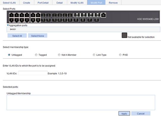
3. Modify the VLANs of a port as described in Table 3.
4. Click Apply.
A progress dialog box appears.
5. Click Close on the progress dialog box when the dialog box prompts that the configuration succeeds.
|
Item |
Description |
|
Select Ports |
Select the ports to be modified. |
|
Select membership type |
Set the member types of the selected ports to be modified in the specified VLANs: · Untagged—Configures the ports to send the traffic of the VLANs after removing the VLAN tags. · Tagged—Configures the ports to send the traffic of the VLANs without removing the VLAN tags. · Not a Member—Removes the ports from the VLANs. |
|
VLAN IDs |
Set the IDs of the VLANs to or from which the selected ports are to be assigned or removed. When you set the VLAN IDs, follow these guidelines: · You cannot configure an access port as an untagged member of a nonexistent VLAN. · When you configure an access port as a tagged member of a VLAN, or configure a trunk port as an untagged member of multiple VLANs in bulk, the link type of the port is automatically changed into hybrid. · You can configure a hybrid port as a tagged or untagged member of a VLAN only if the VLAN is an existing, static VLAN. |
VLAN configuration example
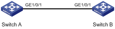
Network requirements
As shown in Figure 11, trunk port GigabitEthernet 1/0/1 of Switch A is connected to trunk port GigabitEthernet 1/0/1 of Switch B.
Configure the PVID of GigabitEthernet 1/0/1 as VLAN 100, and configure GigabitEthernet 1/0/1 to permit packets of VLAN 2, VLAN 6 through VLAN 50, and VLAN 100 to pass through.
Configuring Switch A
1. Configure GigabitEthernet 1/0/1 as a trunk port and configure VLAN 100 as the PVID:
a. Select Device > Port Management from the navigation tree.
b. Click Setup to enter the page for setting ports.
c. Select Trunk in the Link Type list, select the PVID box, and then enter PVID 100.
d. Select GigabitEthernet 1/0/1 on the chassis front device panel.
e. Click Apply.
Figure 12 Configuring GigabitEthernet 1/0/1 as a trunk port and its PVID as 100

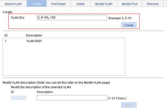
2. Create VLAN 2, VLAN 6 through VLAN 50, and VLAN 100:
a. Select Network > VLAN from the navigation tree.
b. Click Create to enter the page for creating VLANs.
c. Enter VLAN IDs 2, 6-50, 100.
d. Click Apply.
Figure 13 Creating VLAN 2, VLAN 6 through VLAN 50, and VLAN 100
3. Assign GigabitEthernet 1/0/1 to VLAN 100 as an untagged member:
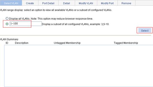
a. Click Select VLAN to enter the page for selecting VLANs.
b. Select the option before Display a subnet of all configured VLANs, and enter 1-100 in the field.
c. Click Select.
Figure 14 Setting a VLAN range
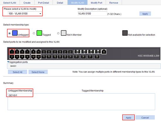
d. Click Modify VLAN to enter the page for modifying the ports in a VLAN.
e. Select 100 – VLAN 0100 in the Please select a VLAN to modify: list, select the Untagged option, and select GigabitEthernet 1/0/1 on the chassis front device panel.
f. Click Apply.
A configuration progress dialog box appears.
g. After the configuration process is complete, click Close.
Figure 15 Assigning GigabitEthernet 1/0/1 to VLAN 100 as an untagged member
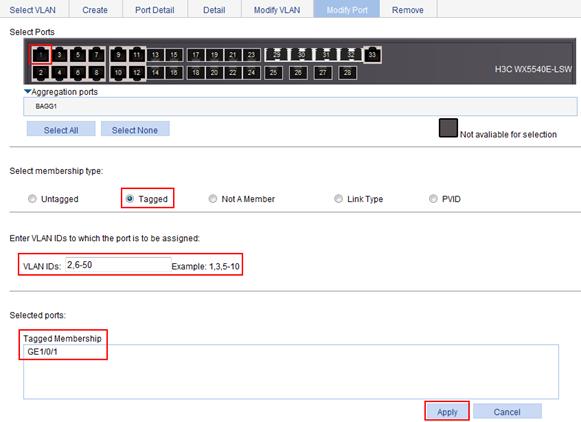
4. Assign GigabitEthernet 1/0/1 to VLAN2, and VLAN 6 through VLAN 50 as a tagged member:
a. Click Modify Port to enter the page for modifying the VLANs to which a port belongs.
b. Select GigabitEthernet 1/0/1 on the chassis front device panel, select the Tagged option, and enter VLAN IDs 2, 6-50.
c. Click Apply.
A configuration progress dialog box appears.
d. After the configuration process is complete, click Close in the dialog box.
Figure 16 Assigning GigabitEthernet 1/0/1 to VLAN 2 and to VLANs 6 through 50 as a tagged member
Configuring Switch B
Configure Switch B as you configure Switch A.
Before creating a VLAN interface, you must create the corresponding VLAN in Network > VLAN. For more information, see "Configuring VLANs."
Overview
For hosts of different VLANs to communicate, you must use a router or Layer 3 switch to perform layer 3 forwarding. To achieve this, you can use VLAN interfaces.
VLAN interfaces are virtual interfaces used for Layer 3 communication between different VLANs. They do not exist as physical entities on devices. For each VLAN, you can create one VLAN interface. You can assign the VLAN interface an IP address, and specify it as the gateway of the VLAN to forward the traffic destined for an IP network segment different from that of the VLAN.
Creating a VLAN interface
When you create a VLAN interface, you can select to assign an IPv4 address to the VLAN interface in this step or in a separate step. If you do not select to configure an IP address, you can create the VLAN interface, and configure an IP address for the VLAN interface by modifying it.
To create a VLAN interface:
1. Select Network > VLAN Interface from the navigation tree.
2. Click Create to enter the page for creating a VLAN interface.
Figure 17 Creating a VLAN interface
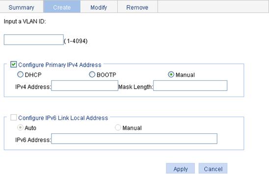
3. Configure the VLAN interface as described in Table 4.
4. Click Apply.
|
Item |
Description |
||
|
Input a VLAN ID: |
Enter the ID of the VLAN interface to be created. Before creating a VLAN interface, make sure the corresponding VLAN exists. |
||
|
Configure Primary IPv4 Address |
DHCP |
Configure the way in which the VLAN interface gets an IPv4 address. Allow the VLAN interface to get an IP address automatically by selecting the DHCP or BOOTP option. Otherwise, select the Manual option to manually assign the VLAN interface an IP address. The device does not suport to get an IP address through DHCP or BOOTP. |
These items are available after you select the Configure Primary IPv4 Address box. |
|
BOOTP |
|||
|
Manual |
|||
|
IPv4 Address |
Configure an IPv4 address for the VLAN interface. This field is available after you select the Manual option. |
||
|
Mask Length |
Set the subnet mask length (or enter a mask in dotted decimal notation format). This field is available after you select the Manual option. |
||
|
Configure IPv6 Link Local Address |
Auto |
Configure the way in which the VLAN interface gets an IPv6 link-local address. Select the Auto or Manual option: · Auto—The device automatically assigns a link-local address to the VLAN interface based on the link-local address prefix (FE80::/64) and the link-layer address of the VLAN interface. · Manual—Requires manual assignment. |
These items are available after you select the Configure IPv6 Link Local Address box. The device does not support IPv6 addresses. |
|
Manual |
|||
|
IPv6 Address |
Configure an IPv6 link-local address for the VLAN interface. This field is available after you select the Manual option. The prefix of the IPv6 link-local address you enter must be FE80::/64. |
||
Modifying a VLAN interface
By modifying a VLAN interface, you can assign an IPv4 address to the VLAN interface, and shut down or bring up the VLAN interface.
After you modify the IPv4 address and status for a selected VLAN interface on the page for modifying VLAN interfaces, you must click the correct Apply button to submit the modification.
After you change the IP address of the VLAN interface you are using to log in to the device, you will be disconnected from the device. You can use the changed IP address to re-log in.
1. Select Network > VLAN Interface from the navigation tree.
2. Click the Modify tab to enter the page for modifying a VLAN interface.
Figure 18 Modifying a VLAN interface
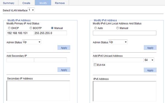
3. Modify a VLAN interface as described in Table 5.
4. Click Apply.
|
Item |
Description |
|
||
|
Select VLAN Interface |
Select the VLAN interface to be configured. The VLAN interfaces available for selection in the list are those created on the page for creating VLAN interfaces. |
|
||
|
Modify IPv4 Address |
DHCP |
Configure the way in which the VLAN interface gets an IPv4 address. Allow the VLAN interface to get an IP address automatically by selecting the DHCP or BOOTP option, or manually assign the VLAN interface an IP address by selecting the Manual option. In the latter case, you must set the mask length or enter a mask in dotted decimal notation format. The device does not suport to get an IP address through DHCP or BOOTP. |
||
|
BOOTP |
||||
|
Manual |
||||
|
Admin Status |
Select Up or Down from the Admin Status list to bring up or shut down the selected VLAN interface. When the VLAN interface fails, shut down and then bring up the VLAN interface, which may restore it. By default, a VLAN interface is down if all Ethernet ports in the VLAN are down. Otherwise, the VLAN interface is up. When you set the admin status, follow these guidelines: · The current VLAN interface state in the Modify IPv4 Address frame changes as the VLAN interface state is modified in the Admin Status list. · The state of each port in the VLAN is independent of the VLAN interface state. |
|||
|
Add Secondary IP |
Add a secondary IP address for the VLAN interface. |
|||
|
Secondary IP Address |
Existing secondary IP addresses. |
|||
|
Modify IPv6 Address (The device does not support IPv6 addresses.) |
Auto |
Configure the way in which the VLAN interface gets an IPv6 link-local address. Select the Auto or Manual option: · Auto—Indicates that the device automatically assigns a link-local address to the VLAN interface according to the link-local address prefix (FE80::/64) and the link-layer address of the VLAN interface. · Manual—Configures an IPv6 link-local address for the VLAN interface manually. |
||
|
Manual |
||||
|
Admin Status |
Select Up or Down from the Admin Status list to bring up or shut down the selected VLAN interface. When the VLAN interface fails, shut down and then enable the VLAN interface, which may restore it. By default, a VLAN interface is down if all Ethernet ports in the VLAN are down. Otherwise, the VLAN interface is up. When you set the admin status, follow these guidelines: · The current VLAN interface state in the Modify IPv4 Address and Modify IPv6 Address frames changes as the VLAN interface state is modified in the Admin Status list. · The state of each port in the VLAN is independent of the VLAN interface state. |
|||
|
Add IPv6 Unicast Address |
Assign an IPv6 site-local address or global unicast address to the VLAN interface. Enter an IPv6 address in the field and select a prefix length in the list next to it. The prefix of the IPv6 address you entered cannot be FE80::/10, the prefix of the link-local address. The prefix of the IPv6 site-local address you enter must be FEC0::/10. |
|||
|
EUI-64 |
Select the box to generate IPv6 site-local addresses or global unicast addresses in the 64-bit Extended Unique Identifier (EUI-64) format. If the EUI-64 box is not specified, manually configured IPv6 site-local addresses or global unicast addresses are used. |
|||
Overview
A voice VLAN is dedicated to voice traffic. After the ports connecting to voice devices are assigned to a voice VLAN, the system automatically modifies the QoS parameters for the voice traffic. This improves transmission priority and ensures voice quality.
Common voice devices include IP phones and integrated access devices (IADs). Only IP phones are used in the voice VLAN configuration examples in this document.
OUI addresses
A device determines whether a received packet is a voice packet by examining its source MAC address. If the source MAC address of a received packet matches an organizationally unique identifier (OUI) in the voice device OUI list maintained by the switch, the packet is regarded as a voice packet.
You can remove default OUI addresses and if needed, add them to the OUI list after their removal. You can add OUI addresses to the OUI list maintained by the device, or use the default OUI list shown in Table 6 for voice traffic identification.
|
Number |
OUI Address |
Vendor |
|
1 |
0001-e300-0000 |
Siemens phone |
|
2 |
0003-6b00-0000 |
Cisco phone |
|
3 |
0004-0d00-0000 |
Avaya phone |
|
4 |
00d0-1e00-0000 |
Pingtel phone |
|
5 |
0060-b900-0000 |
Philips/NEC phone |
|
6 |
00e0-7500-0000 |
Polycom phone |
|
7 |
00e0-bb00-0000 |
3Com phone |
An OUI address is usually the first 24 bits of a MAC address (in binary format). It is a globally unique identifier assigned to a vendor by the IEEE. However, OUI addresses are used by the system to determine whether received packets are voice packets and they are the results of the AND operation of a MAC address and a mask in this document. For more information, see "Adding OUI addresses to the OUI list."
Voice VLAN assignment modes
A port connected to a voice device (for example, an IP phone) can be assigned to a voice VLAN in one of the following modes:
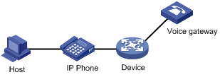
· Automatic mode—The system matches the source MAC addresses in the untagged packets sent by the IP phone upon its power-on against the OUI list. If a match is found, the system automatically assigns the receiving port to a voice VLAN, issues ACL rules, and configures the packet precedence. You can configure an aging timer for the voice VLAN. The system will remove the port from the voice VLAN when the aging timer expires if no voice packet is received on the port during the aging timer. Assigning ports to and removing ports from a voice VLAN are automatically performed. Automatic mode is suitable for scenarios where PCs and IP phones connected in series access the network through the device and ports on the device transmit both voice traffic and data traffic at the same time, as shown in Figure 19. When the voice VLAN works normally, if the system reboots, the system reassigns ports in automatic voice VLAN assignment mode to the voice VLAN after the reboot, ensuring that existing voice connections can work normally. In this case, voice traffic streams do not trigger port assignment to the voice VLAN.
Figure 19 PCs and IP phones connected in series access the network
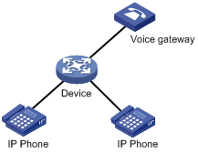
· Manual mode—You must assign the port to a voice VLAN manually. Then, the system matches the source MAC addresses in the packets against the OUI addresses. If a match is found, the system issues ACL rules and configures the packet precedence. In this mode, assigning ports to and removing ports from a voice VLAN are performed manually. Manual mode is suitable for scenarios where only IP phones access the network through the device, and ports on the device transmit only voice traffic, as shown in Figure 20. In this mode, ports assigned to a voice VLAN transmit voice traffic exclusively, which prevents the impact of data traffic on the transmission of voice traffic.
Figure 20 Only IP phones access the network
Both modes forward tagged packets according to their tags. Table 7 and Table 8 list the configurations required for ports of different link types to support tagged or untagged voice traffic sent from IP phones when different voice VLAN assignment modes are configured.
If the port that receives tagged voice traffic from an IP phone is configured with 802.1X authentication and a guest VLAN, assign different VLAN IDs to the voice VLAN, the PVID of the accessing port, and the 802.1X guest VLAN.
When IP phones send untagged voice traffic, the voice traffic receiving ports on must operate in manual voice VLAN assignment mode. To implement the voice VLAN feature, you must configure the PVID of each receiving port as the voice VLAN. As a result, you cannot implement 802.1X authentication.
|
Port link type |
Voice VLAN assignment mode supported for tagged voice traffic |
Configuration requirements |
|
Access |
N/A |
N/A |
|
Trunk |
Automatic and manual |
In automatic mode, the PVID of the port cannot be the voice VLAN. In manual mode, the PVID of the port cannot be the voice VLAN. Configure the port to permit packets from the voice VLAN to pass through. |
|
Hybrid |
Automatic and manual |
In automatic mode, the PVID of the port cannot be the voice VLAN. In manual mode, the PVID of the port cannot be the voice VLAN. Configure the port to permit packets from the voice VLAN to pass through tagged. |
|
Port link type |
Voice VLAN assignment mode supported for untagged voice traffic |
Configuration requirements |
|
Access |
Manual |
Configure the PVID of the port as the voice VLAN. |
|
Trunk |
Manual |
Configure the PVID of the port as the voice VLAN and configure the port to permit packets from the voice VLAN to pass through. |
|
Hybrid |
Manual |
Configure the PVID of the port as the voice VLAN and configure the port to permit packets from the voice VLAN to pass through untagged. |
Security mode and normal mode of voice VLANs
Depending on their inbound packet filtering mechanisms, voice VLAN-enabled ports operate in one of the following modes:
· Normal mode—In this mode, both voice packets and non-voice packets are allowed to pass through a voice VLAN-enabled inbound port. When receiving a voice packet, the port forwards it without checking its source MAC address against the OUI addresses configured for the device. If the default VLAN of the port is the voice VLAN and the port operates in manual VLAN assignment mode, the port forwards all received untagged packets in the voice VLAN. In normal mode, the voice VLANs are vulnerable to traffic attacks. Vicious users can forge a large amount of voice packets and send them to voice VLAN-enabled ports to consume the voice VLAN bandwidth, affecting normal voice communication.
· Security mode—In this mode, only voice packets whose source MAC addresses comply with the recognizable OUI addresses can pass through the voice VLAN-enabled inbound port, but all other packets are dropped.
In a safe network, you can configure the voice VLANs to operate in normal mode. This reduces the consumption of system resources due to source MAC addresses checking.
H3C recommends you not transmit both voice packets and non-voice packets in a voice VLAN. If you have to, first make sure the voice VLAN security mode is disabled.
Table 9 How a voice VLAN-enable port processes packets in security/normal mode
|
Voice VLAN operating mode |
Packet type |
Packet processing mode |
|
Security mode |
Untagged packets |
If the source MAC address of a packet matches an OUI address configured for the device, it is forwarded in the voice VLAN. Otherwise, it is dropped. |
|
Packets carrying the voice VLAN tag |
||
|
Packets carrying other tags |
Forwarded or dropped depending on whether the port allows packets of these VLANs to pass through. |
|
|
Normal mode |
Untagged packets |
The port does not check the source MAC addresses of inbound packets. All types of packets can be transmitted in the voice VLAN. |
|
Packets carrying the voice VLAN tag |
||
|
Packets carrying other tags |
Forwarded or dropped depending on whether the port allows packets of these VLANs to pass through. |
Configuration guidelines
When you configure the voice VLAN function, follow these guidelines:
· To remove a VLAN functioning as a voice VLAN, disable its voice VLAN function first.
· In automatic voice VLAN assignment mode, a hybrid port can process only tagged voice traffic. However, the protocol-based VLAN function requires hybrid ports to process untagged traffic. If a VLAN is configured as the voice VLAN and a protocol-based VLAN at the same time, the protocol-based VLAN cannot be associated with the port.
· Only one VLAN is supported and only an existing static VLAN can be configured as the voice VLAN.
· Do not enable the voice VLAN function on a link aggregation group member port.
· After you assign a port operating in manual voice VLAN assignment mode to the voice VLAN, the voice VLAN takes effect.
Recommended voice VLAN configuration procedure
Before you configure the voice VLAN, you must create the VLAN and configure the link type of each port to be assigned to the VLAN. Because VLAN 1 is the system-default VLAN, you do not need to create it. However, you cannot configure it as the voice VLAN. For information about port link types, see "Managing ports."
Recommended configuration procedure for a port in automatic voice VLAN assignment mode
|
Step |
Remarks |
|
Optional. Configure the voice VLAN to operate in security mode, and configure the aging timer. |
|
|
Required. Configure the voice VLAN assignment mode of a port as automatic, and enable the voice VLAN function on the port. By default, the voice VLAN assignment mode of a port is automatic, and the voice VLAN function is disabled on a port. |
|
|
Optional. The system supports up to 16 OUI addresses. By default, the system is configured with seven OUI addresses, as shown in Table 6. |
Recommended configuration procedure for a port in manual voice VLAN assignment mode
|
Step |
Remarks |
|
Optional. Configure the voice VLAN to operate in security mode, and configure the aging timer. |
|
|
2. Assigning the port to the voice VLAN. |
Required. After an access port is assigned to the voice VLAN, the voice VLAN automatically becomes the default VLAN of the access port. For more information, see "Configuring VLANs." |
|
3. Configuring the voice VLAN as the default VLAN of a hybrid or trunk port. |
Optional. This task is required if the incoming voice traffic is untagged and the link type of the receiving port is trunk or hybrid. If the incoming voice traffic is tagged, do not perform this task. For more information, see "Managing ports." |
|
Required. Configure the voice VLAN assignment mode of a port as manual, and enable voice VLAN on the port. By default, the voice VLAN assignment mode of a port is automatic, and voice VLAN is disabled on a port. |
|
|
Optional. You can configure up to 16 OUI addresses. By default, the system is configured with the seven OUI addresses shown in Table 6. |
Configuring voice VLAN globally
1. Select Network > Voice VLAN from the navigation tree.
2. Click the Setup tab.
Figure 21 Configuring voice VLAN
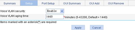
3. Configure the global voice VLAN settings as described in Table 10.
4. Click Apply.
|
Item |
Description |
|
Voice VLAN security |
Select Enable or Disable in the list to enable or disable the voice VLAN security mode. By default, the voice VLANs operate in security mode. |
|
Voice VLAN aging time |
Set the voice VLAN aging timer. The voice VLAN aging timer setting only applies to a port in automatic voice VLAN assignment mode. The voice VLAN aging timer starts as soon as the port is assigned to the voice VLAN. If no voice packet has been received before the timer expires, the port is removed from the voice VLAN. |
Configuring voice VLAN on ports
1. Select Network > Voice VLAN from the navigation tree.
2. Click the Port Setup tab.
Figure 22 Configuring voice VLAN on ports
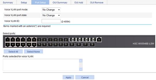
3. Configure the voice VLAN function for ports as described in Table 11.
4. Click Apply.
|
Item |
Description |
|
Voice VLAN port mode |
Set the voice VLAN assignment mode of a port to: · Auto—Automatic voice VLAN assignment mode. · Manual—Manual voice VLAN assignment mode. |
|
Voice VLAN port state |
Select Enable or Disable in the list to enable or disable the voice VLAN function on the port. |
|
Voice VLAN ID |
Set the voice VLAN ID of a port when the voice VLAN port state is set to Enable. |
|
Select Ports |
Select the port on the chassis front panel. You can select multiple ports to configure them in bulk. The numbers of the selected ports will be displayed in the Ports selected for voice VLAN field. To set the voice VLAN assignment mode of a port to automatic, you must make sure the link type of the port is trunk or hybrid, and that the port does not belong to the voice VLAN. |
Adding OUI addresses to the OUI list
1. Select Network > Voice VLAN from the navigation tree.
2. Click the OUI Add tab.
Figure 23 Adding OUI addresses to the OUI list
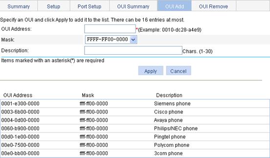
3. Add an OUI address to the list as described in Table 12.
4. Click Apply.
|
Item |
Description |
|
OUI Address |
Set the source MAC address of voice traffic. |
|
Mask |
Set the mask length of the source MAC address. |
|
Description |
Set the description of the OUI address entry. |
Voice VLAN configuration examples
Configuring voice VLAN on a port in automatic voice VLAN assignment mode
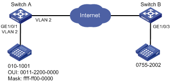
Network requirements
As shown in Figure 24:
· Configure VLAN 2 as the voice VLAN allowing only voice traffic to pass through.
· The IP phone connected to hybrid port GigabitEthernet 1/0/1 sends untagged voice traffic.
· GigabitEthernet 1/0/1 operates in automatic VLAN assignment mode. Set the voice VLAN aging timer to 30 minutes.
· Configure GigabitEthernet 1/0/1 to allow voice packets whose source MAC addresses match the OUI addresses specified by OUI address 0011-2200-0000 and mask ffff-ff00-0000. The description of the OUI address entry is test.
Configuring Switch A
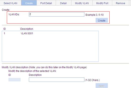
1. Create VLAN 2:
a. Select Network > VLAN from the navigation tree.
b. Click the Create tab.
c. Enter VLAN ID 2.
d. Click Create.
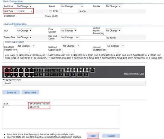
2. Configure GigabitEthernet 1/0/1 as a hybrid port:
a. Select Device > Port Management from the navigation tree.
b. Click the Setup tab.
c. Select Hybrid from the Link Type list.
d. Select GigabitEthernet 1/0/1 from the chassis front panel.
e. Click Apply.
Figure 26 Configuring GigabitEthernet 1/0/1 as a hybrid port
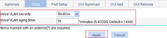
3. Configure the voice VLAN function globally:
a. Select Network > Voice VLAN from the navigation tree.
b. Click the Setup tab.
c. Select Enable from the Voice VLAN security list.
d. Set the voice VLAN aging timer to 30 minutes.
e. Click Apply.
Figure 27 Configuring the voice VLAN function globally
4. Configure voice VLAN on GigabitEthernet 1/0/1:
a. Click the Port Setup tab.
b. Select Auto from the Voice VLAN port mode list.
c. Select Enable from the Voice VLAN port state list.
d. Enter voice VLAN ID 2.
e. Select GigabitEthernet 1/0/1 from the chassis front panel.
f. Click Apply.
Figure 28 Configuring voice VLAN on GigabitEthernet 1/0/1

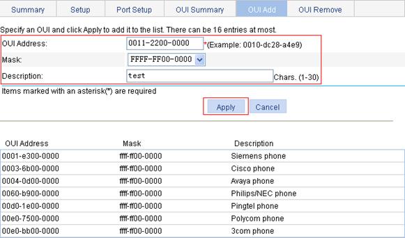
5. Add OUI addresses to the OUI list:
a. Click the OUI Add tab.
b. Enter OUI address 0011-2200-0000.
c. Select FFFF-FF00-0000 from the Mask list.
d. Enter description string test.
e. Click Apply.
Figure 29 Adding OUI addresses to the OUI list
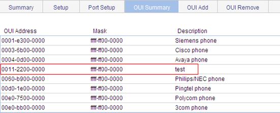
Verifying the configuration
1. When you complete the preceding configurations, the OUI Summary tab is displayed by default, as shown in Figure 30. You can view the information about the newly-added OUI address.
Figure 30 Displaying the current OUI list of the device
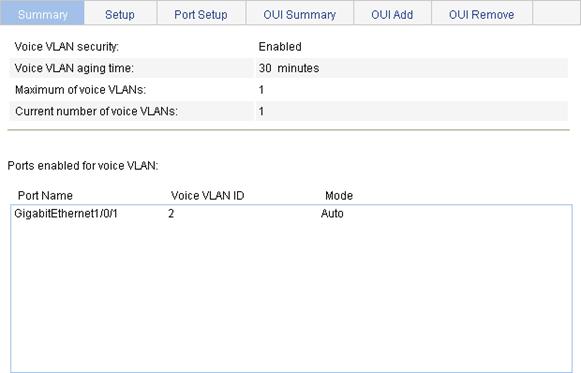
2. Click the Summary tab to enter the page shown in Figure 31.
You can view the current voice VLAN information.
Figure 31 Displaying voice VLAN information
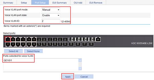
Configuring a voice VLAN on a port in manual voice VLAN assignment mode
Network requirements
As shown in Figure 32:
· Configure VLAN 2 as a voice VLAN that carries only voice traffic.
· The IP phone connected to hybrid port GigabitEthernet 1/0/1 sends untagged voice traffic.
· GigabitEthernet 1/0/1 operates in manual voice VLAN assignment mode, and allows voice packets whose source MAC addresses match the OUI addresses specified by OUI address 0011-2200-0000 and mask ffff-ff00-0000 to pass through. The description of the OUI address entry is test.
Configuring Switch A
1. Create VLAN 2:
a. Select Network > VLAN from the navigation tree.
b. Click the Create tab.
c. Enter VLAN ID 2.
d. Click Create.
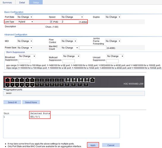
2. Configure GigabitEthernet 1/0/1 as a hybrid port, and configure its default VLAN as VLAN 2:
a. Select Device > Port Management from the navigation tree.
b. Click the Setup tab.
c. Select Hybrid from the Link Type list.
d. Select the PVID box, and enter 2 in the field.
e. Select GigabitEthernet 1/0/1 from the chassis front panel.
f. Click Apply.
Figure 34 Configuring GigabitEthernet 1/0/1 as a hybrid port
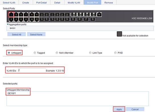
3. Assign GigabitEthernet 1/0/1 to VLAN 2 as an untagged member:
a. Select Network > VLAN from the navigation tree.
b. Click the Modify Port tab.
c. Select GigabitEthernet 1/0/1 from the chassis front panel.
d. Select the Untagged option.
f. Click Apply.
A configuration progress dialog box appears.
g. After the configuration process is complete, click Close.
Figure 35 Assigning GigabitEthernet 1/0/1 to VLAN 2 as an untagged member
4. Configure voice VLAN on GigabitEthernet 1/0/1:
a. Select Network > Voice VLAN from the navigation tree.
b. Click the Port Setup tab.
c. Select Manual from the Voice VLAN port mode list.
d. Select Enable from the Voice VLAN port state list.
e. Enter 2 in the VLAN IDs field.
f. Select GigabitEthernet 1/0/1 from the chassis front panel.
g. Click Apply.
Figure 36 Configuring voice VLAN on GigabitEthernet 1/0/1
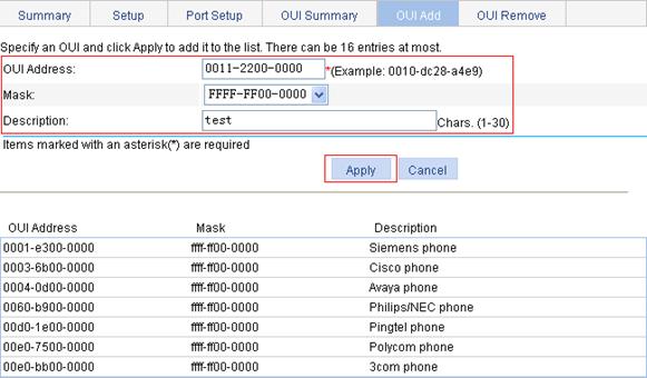
5. Add OUI addresses to the OUI list:
a. Click the OUI Add tab.
b. Enter OUI address 0011-2200-0000.
c. Select FFFF-FF00-0000 as the mask.
d. Enter description string test.
e. Click Apply.
Figure 37 Adding OUI addresses to the OUI list
Verifying the configuration
1. When you complete the preceding configurations, the OUI Summary tab is displayed by default, as shown in Figure 38. You can view the information about the newly-added OUI address.
Figure 38 Displaying the current OUI list of the device

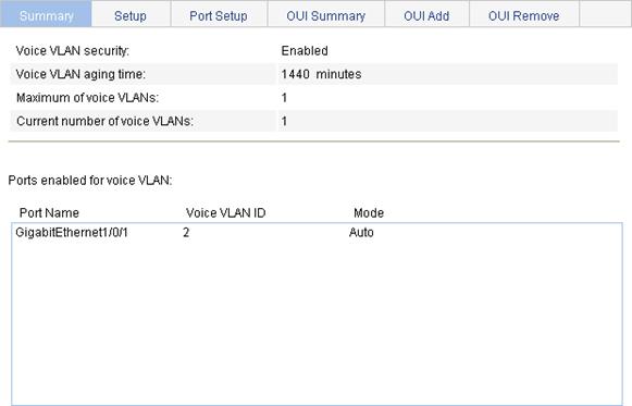
2. Click the Summary tab to enter the page shown in Figure 39.
You can view the current voice VLAN information.
Figure 39 Displaying the current voice VLAN information
MAC address configurations related to interfaces apply to Layer 2 Ethernet interfaces and Layer 2 aggregate interfaces only.
This document covers only the configuration of unicast MAC address entries, including static, dynamic, and destination blackhole entries.
Overview
To reduce single-destination packet flooding in a switched LAN, an Ethernet device uses a MAC address table for forwarding frames. This table describes from which port a MAC address (or host) can be reached. When forwarding a single-destination frame, the device first looks up the destination MAC address of the frame in the MAC address table for a match. If the device finds an entry, it forwards the frame out of the outgoing port in the entry. If the device does not find an entry, it floods the frame out of all but the incoming port.
How a MAC address entry is created
The device automatically learns entries in the MAC address table, or you can add them manually.
MAC address learning
The device can automatically populate its MAC address table by learning the source MAC addresses of incoming frames on each port.
When a frame arrives at a port, Port A, for example, the device performs the following tasks:
· Verifies the source MAC address (for example, MAC-SOURCE) of the frame.
· Looks up the source MAC address in the MAC address table.
· Updates an entry if it finds one. If the device does not find an entry, it adds an entry for MAC-SOURCE and Port A.
The device performs this learning process each time it receives a frame from an unknown source MAC address, until the MAC address table is fully populated.
After learning a source MAC address, when the device receives a frame destined for MAC-SOURCE, the device finds the MAC-SOURCE entry in the MAC address table and forwards the frame out Port A.
To adapt to network changes and prevent inactive entries from occupying table space, an aging mechanism is adopted for dynamic MAC address entries. Each time a dynamic MAC address entry is learned or created, an aging timer starts. If the entry has not updated when the aging timer expires, the device deletes the entry. If the entry has updated before the aging timer expires, the aging timer restarts.
Manually configuring MAC address entries
With dynamic MAC address learning, a device does not distinguish between illegitimate and legitimate frames. For example, when a hacker sends frames with a forged source MAC address to a port different from the one to which the real MAC address is connected, the device creates an entry for the forged MAC address, and forwards frames destined for the legal user to the hacker instead.
To improve port security, you can bind specific user devices to the port by manually adding MAC address entries to the MAC address table of the device.
Types of MAC address entries
A MAC address table can contain the following types of entries:
· Static entries—Manually added and never age out.
· Dynamic entries—Manually added or dynamically learned, and might age out.
· Blackhole entries—Manually configured and never age out. They are configured for filtering out frames with specific destination MAC addresses. For example, to block all packets destined for a specific user for security concerns, you can configure the MAC address of this user as a blackhole MAC address entry.
A static or blackhole MAC address entry can overwrite a dynamic MAC address entry, but not vice versa.
MAC address table-based frame forwarding
When forwarding a frame, the device adopts the following forwarding modes based on the MAC address table:
· Unicast mode—If an entry is available for the destination MAC address, the device forwards the frame out of the outgoing port indicated by the MAC address entry.
· Broadcast mode—If the device receives a frame with all Fs as the destination address, or no entry is available for the destination MAC address, the device floods the frame to all the interfaces except the receiving interface.
Displaying and configuring MAC address entries
1. Select Network > MAC from the navigation tree.
The system automatically displays the MAC tab, which shows all the MAC address entries on the device.

2. Click Add in the bottom to enter the page for creating MAC address entries.
Figure 41 Creating a MAC address entry
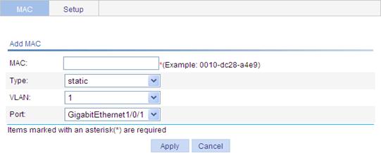
3. Configure a MAC address entry.
4. Click Apply.
|
Item |
Description |
|
MAC |
Set the MAC address to be added. |
|
Type |
Set the type of the MAC address entry: · Static—Static MAC address entries that never age out. · Dynamic—Dynamic MAC address entries that will age out. · Blackhole—Blackhole MAC address entries that never age out. The tab displays the following types of MAC address entries: · Config static—Static MAC address entries manually configured by the users. · Config dynamic—Dynamic MAC address entries manually configured by the users. · Blackhole—Blackhole MAC address entries. · Learned—Dynamic MAC address entries learned by the device. · Other—Other types of MAC address entries. |
|
VLAN ID |
Set the ID of the VLAN to which the MAC address belongs. |
|
Port |
Set the port to which the MAC address belongs. This port must belong to the specified VLAN. |
Setting the aging time of MAC address entries
1. Select Network > MAC from the navigation tree.
2. Click the Setup tab to enter the page for setting the MAC address entry aging time.
Figure 42 Setting the aging time for MAC address entries
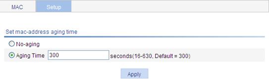
3. Configure the aging time for MAC address entries.
4. Click Apply.
|
Item |
Description |
|
No-aging |
Specify that the MAC address entry never ages out. |
|
Aging time |
Set the aging time for the MAC address entry. |
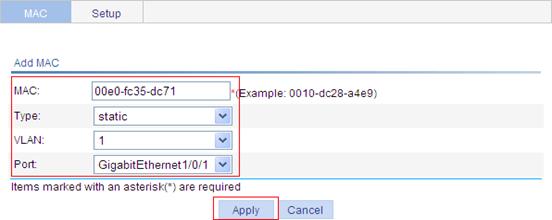
MAC address table configuration example
Network requirements
Use the Web-based NMS to configure the MAC address table of the device. Add a static MAC address 00e0-fc35-dc71 under GigabitEthernet 1/0/1 in VLAN 1.
Creating a static MAC address entry
1. Select Network > MAC from the navigation tree.
By default, the MAC tab is displayed.
2. Click Add.
3. Configure a MAC address entry:
a. Enter MAC address 00e0-fc35-dc71.
b. Select static in the Type list.
c. Select 1 in the VLAN list.
d. Select GigabitEthernet1/0/1 in the Port list.
4. Click Apply.
Figure 43 Creating a static MAC address entry
Overview
As a Layer 2 management protocol, the Spanning Tree Protocol (STP) eliminates Layer 2 loops by selectively blocking redundant links in a network, and allows for link redundancy.
Like many other protocols, STP evolves as the network grows. The later versions of STP are Rapid Spanning Tree Protocol (RSTP) and Multiple Spanning Tree Protocol (MSTP). This chapter describes the characteristics of STP, RSTP, and MSTP.
Introduction to STP
STP was developed based on the 802.1d standard of IEEE to eliminate loops at the data link layer in a LAN. Devices running this protocol detect loops in the network by exchanging information with one another, and eliminate loops by selectively blocking certain ports to prune the loop structure into a loop-free tree structure. This avoids proliferation and infinite cycling of packets that would occur in a loop network and prevents decreased performance of network devices caused by duplicate packets received.
In the narrow sense, STP refers to the IEEE 802.1d STP. In the broad sense, STP refers to the IEEE 802.1d STP and various improved spanning tree protocols derived from that protocol.
Protocol packets of STP
STP uses bridge protocol data units (BPDUs), also known as configuration messages, as its protocol packets.
STP-enabled network devices exchange BPDUs to establish a spanning tree. BPDUs contain sufficient information for the network devices to complete spanning tree calculation.
In STP, BPDUs have the following types:
· Configuration BPDUs—Used for calculating a spanning tree and maintaining the spanning tree topology.
· Topology change notification (TCN) BPDUs—Used for notifying the concerned devices of network topology changes, if any.
Basic concepts in STP
Root bridge
A tree network must have a root bridge. There is only one root bridge in the entire network. The root bridge is not fixed, but it can change along with changes of the network topology.
When you initialize a network, each device generates and sends out BPDUs periodically with itself as the root bridge. After network convergence, only the root bridge generates and sends out configuration BPDUs at a certain interval, and the other devices just forward the BPDUs.
Root port
Designated bridge and designated port
Table 15 Description of designated bridges and designated ports:
|
Classification |
Designated bridge |
Designated port |
|
For a device |
Device directly connected to the local device and responsible for forwarding BPDUs to the local device. |
Port through which the designated bridge forwards BPDUs to the local device. |
|
For a LAN |
Device responsible for forwarding BPDUs to this LAN segment. |
Port through which the designated bridge forwards BPDUs to this LAN segment. |
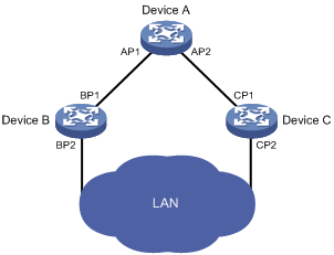
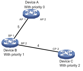
As shown in Figure 44, AP1 and AP2, BP1 and BP2, and CP1 and CP2 are ports on Device A, Device B, and Device C, respectively.
· If Device A forwards BPDUs to Device B through AP1, the designated bridge for Device B is Device A, and the designated port of Device B is port AP1 on Device A.
· Device B and Device C are connected to the LAN. If Device B forwards BPDUs to the LAN, the designated bridge for the LAN is Device B, and the designated port for the LAN is the port BP2 on Device B.
Figure 44 Designated bridges and designated ports
Path cost
Path cost is a reference value used for link selection in STP. By calculating path costs, STP selects relatively robust links and blocks redundant links, and finally prunes the network into a loop-free tree.
All the ports on the root bridge are designated ports.
How STP works
The devices on a network exchange BPDUs to identify the network topology. Configuration BPDUs contain sufficient information for the network devices to complete spanning tree calculation. A configuration BPDU includes the following important fields:
· Root bridge ID—Consisting of the priority and MAC address of the root bridge.
· Root path cost—Cost of the path to the root bridge.
· Designated bridge ID—Consisting of the priority and MAC address of the designated bridge.
· Designated port ID—Designated port priority plus port name.
· Message age—Age of the configuration BPDU while it propagates in the network.
· Max age—Maximum age of the configuration BPDU can be maintained on a device.
· Hello time—Configuration BPDU interval.
· Forward delay—Delay used by STP bridges to transit the state of the root and designated ports to forwarding.
For simplicity, the descriptions and examples in this document involve only the following fields in the configuration BPDUs:
· Root bridge ID (represented by device priority).
· Root path cost.
· Designated bridge ID (represented by device priority).
· Designated port ID (represented by port name).
Calculation process of the STP algorithm
1. Initialize the state.
2. Select the optimum configuration BPDU.
Each device sends out its configuration BPDU, and receives configuration BPDUs from other devices.
Table 16 Selection of the optimum configuration BPDU
|
Step |
Actions |
|
1 |
When the device receives a configuration BPDU on a port, it performs the following actions: · If the received configuration BPDU has a lower priority than that of the configuration BPDU generated by the port, the device discards the received configuration BPDU, and does not process the configuration BPDU of this port. · If the received configuration BPDU has a higher priority than that of the configuration BPDU generated by the port, the device replaces the content of the configuration BPDU generated by the port with the content of the received configuration BPDU. |
|
2 |
The device compares the configuration BPDUs of all the ports, and chooses the optimum configuration BPDU. |
Configuration BPDU comparison uses the following principles:
¡ The configuration BPDU that has the lowest root bridge ID has the highest priority.
¡ If all the configuration BPDUs have the same root bridge ID, their root path costs are compared. For example, the root path cost in a configuration BPDU plus the path cost of a receiving port is S. The configuration BPDU with the smallest S value has the highest priority.
¡ If all configuration BPDUs have the same S value, their designated bridge IDs, designated port IDs, and the IDs of the receiving ports are compared in sequence. The configuration BPDU containing a smaller ID wins out.
3. Select the root bridge.
Initially, each STP-enabled device on the network assumes itself to be the root bridge, with the root bridge ID being its own device ID. By exchanging configuration BPDUs, the devices compare their root bridge IDs to elect the device with the smallest root bridge ID as the root bridge.
4. Select the root port and designated ports on a non-root device.
Table 17 Selection of the root port and designated ports
|
Step |
Description |
|
1 |
A non-root device regards the port on which it received the optimum configuration BPDU as the root port. |
|
2 |
Based on the configuration BPDU and the path cost of the root port, the device calculates a designated port configuration BPDU for each of the rest ports. · The root bridge ID is replaced with that of the configuration BPDU of the root port. · The root path cost is replaced with that of the configuration BPDU of the root port plus the path cost of the root port. · The designated bridge ID is replaced with the ID of this device. · The designated port ID is replaced with the ID of this port. |
|
3 |
The device compares the calculated configuration BPDU with the configuration BPDU on the port of which the port role is to be defined, and acts depending on the comparison result: · If the calculated configuration BPDU is superior, the device considers this port as the designated port, and it replaces the configuration BPDU on the port with the calculated configuration BPDU, which will be sent out periodically. · If the configuration BPDU on the port is superior, the device blocks this port without updating its configuration BPDU. The blocked port can receive BPDUs but cannot send BPDUs or forward any data. |
When the network topology is stable, only the root port and designated ports forward traffic, and other ports are all in the blocked state—they receive BPDUs but do not forward BPDUs or user traffic.
A tree-shape topology forms upon successful election of the root bridge, the root port on each non-root bridge and the designated ports.
STP calculation process example
The spanning tree calculation process in this example is only a simplified process.
The following example demonstrates how the STP algorithm works. As shown in Figure 45, assume that the priority of Device A is 0, the priority of Device B is 1, the priority of Device C is 2, and the path costs of these links are 5, 10, and 4, respectively.
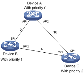
1. Initialize the state of each device.
Table 18 Initial state of each device
|
Device |
Port name |
BPDU of port |
|
Device A |
AP1 |
{0, 0, 0, AP1} |
|
AP2 |
{0, 0, 0, AP2} |
|
|
Device B |
BP1 |
{1, 0, 1, BP1} |
|
BP2 |
{1, 0, 1, BP2} |
|
|
Device C |
CP1 |
{2, 0, 2, CP1} |
|
CP2 |
{2, 0, 2, CP2} |
2. Perform comparisons on each device.
Table 19 Comparison process and result on each device
|
Device |
Comparison process |
BPDU of port after comparison |
|
Device A |
· Port AP1 receives the configuration BPDU of Device B {1, 0, 1, BP1}. Device A finds that the configuration BPDU of the local port {0, 0, 0, AP1} is superior to the received configuration BPDU, and discards the received configuration BPDU. · Port AP2 receives the configuration BPDU of Device C {2, 0, 2, CP1}. Device A finds that the BPDU of the local port {0, 0, 0, AP2} is superior to the received configuration BPDU, and discards the received configuration BPDU. · Device A finds that both the root bridge and designated bridge in the configuration BPDUs of all its ports are itself, so it assumes itself to be the root bridge. It does not make any change to the configuration BPDU of each port, and starts sending out configuration BPDUs periodically. |
AP1: {0, 0, 0, AP1} AP2: {0, 0, 0, AP2} |
|
Device B |
· Port BP1 receives the configuration BPDU of Device A {0, 0, 0, AP1}. Device B finds that the received configuration BPDU is superior to the configuration BPDU of the local port {1, 0, 1, BP1}, and updates the configuration BPDU of BP1. · Port BP2 receives the configuration BPDU of Device C {2, 0, 2, CP2}. Device B finds that the configuration BPDU of the local port {1, 0, 1, BP2} is superior to the received configuration BPDU, and discards the received configuration BPDU. |
BP1: {0, 0, 0, AP1} BP2: {1, 0, 1, BP2} |
|
· Device B compares the configuration BPDUs of all its ports, and determines that the configuration BPDU of BP1 is the optimum configuration BPDU. Then, it uses BP1 as the root port, the configuration BPDUs of which will not be changed. · Based on the configuration BPDU of BP1 and the path cost of the root port (5), Device B calculates a designated port configuration BPDU for BP2 {0, 5, 1, BP2}. · Device B compares the calculated configuration BPDU {0, 5, 1, BP2} with the configuration BPDU of BP2. If the calculated BPDU is superior, BP2 will act as the designated port, and the configuration BPDU on this port will be replaced with the calculated configuration BPDU, which will be sent out periodically. |
Root port BP1: {0, 0, 0, AP1} Designated port BP2: {0, 5, 1, BP2} |
|
|
Device C |
· Port CP1 receives the configuration BPDU of Device A {0, 0, 0, AP2}. Device C finds that the received configuration BPDU is superior to the configuration BPDU of the local port {2, 0, 2, CP1}, and updates the configuration BPDU of CP1. · Port CP2 receives the configuration BPDU of port BP2 of Device B {1, 0, 1, BP2} before the configuration BPDU is updated. Device C finds that the received configuration BPDU is superior to the configuration BPDU of the local port {2, 0, 2, CP2}, and updates the configuration BPDU of CP2. |
CP1: {0, 0, 0, AP2} CP2: {1, 0, 1, BP2} |
|
After comparison: · The configuration BPDU of CP1 is elected as the optimum configuration BPDU, so CP1 is identified as the root port, the configuration BPDUs of which will not be changed. · Device C compares the calculated designated port configuration BPDU {0, 10, 2, CP2} with the configuration BPDU of CP2, and CP2 becomes the designated port, and the configuration BPDU of this port will be replaced with the calculated configuration BPDU. |
Root port CP1: {0, 0, 0, AP2} Designated port CP2: {0, 10, 2, CP2} |
|
|
· Then, port CP2 receives the updated configuration BPDU of Device B {0, 5, 1, BP2}. Because the received configuration BPDU is superior to its own configuration BPDU, Device C launches a BPDU update process. · At the same time, port CP1 receives periodic configuration BPDUs from Device A. Device C does not launch an update process after comparison. |
CP1: {0, 0, 0, AP2} CP2: {0, 5, 1, BP2} |
|
|
After comparison: · Because the root path cost of CP2 (9) (root path cost of the BPDU (5) plus path cost corresponding to CP2 (4)) is smaller than the root path cost of CP1 (10) (root path cost of the BPDU (0) + path cost corresponding to CP2 (10)), the BPDU of CP2 is elected as the optimum BPDU, and CP2 is elected as the root port, the messages of which will not be changed. · After comparison between the configuration BPDU of CP1 and the calculated designated port configuration BPDU, port CP1 is blocked, with the configuration BPDU of the port unchanged, and the port will not receive data from Device A until a spanning tree calculation process is triggered by a new event, for example, the link from Device B to Device C going down. |
Blocked port CP2: {0, 0, 0, AP2} Root port CP2: {0, 5, 1, BP2} |
After the comparison processes described in Table 19, a spanning tree with Device A as the root bridge is established as shown in Figure 46.
Figure 46 Final calculated spanning tree
BPDU forwarding mechanism in STP
The BPDUs are forwarded following these guidelines:
· Upon network initiation, every device regards itself as the root bridge, generates configuration BPDUs with itself as the root, and sends the configuration BPDUs at a regular hello interval.
· If it is the root port that received a configuration BPDU and the received configuration BPDU is superior to the configuration BPDU of the port, the device increases the message age carried in the configuration BPDU following a certain rule, and it starts a timer to time the configuration BPDU while sending this configuration BPDU out of the designated port.
· If the configuration BPDU received on a designated port has a lower priority than the configuration BPDU of the local port, the port immediately sends out its own configuration BPDU in response.
· If a path becomes faulty, the root port on this path will no longer receive new configuration BPDUs and the old configuration BPDUs will be discarded due to timeout. The device will generate configuration BPDUs with itself as the root. This triggers a new spanning tree calculation process to establish a new path to restore the network connectivity.
However, the newly calculated configuration BPDU will not be propagated throughout the network immediately, so the old root ports and designated ports that have not detected the topology change continue forwarding data along the old path. If the new root ports and designated ports begin to forward data as soon as they are elected, a temporary loop may occur.
STP timers
STP calculation involves the following timers:
· Forward delay—The delay time for device state transition. A path failure can cause spanning tree re-calculation to adapt the spanning tree structure to the change. However, the resulting new configuration BPDU cannot propagate throughout the network immediately. If the newly elected root ports and designated ports start to forward data right away, a temporary loop is likely to occur.
For this reason, as a mechanism for state transition in STP, the newly elected root ports or designated ports require twice the forward delay time before transiting to the forwarding state to make sure the new configuration BPDU has propagated throughout the network.
· Hello time—The time interval at which a device sends hello packets to the surrounding devices to make sure the paths are fault-free.
· Max age—A parameter used to determine whether a configuration BPDU held by the device has expired. A configuration BPDU beyond the max age will be discarded.
Introduction to RSTP
Developed based on the 802.1w standard of IEEE, RSTP is an optimized version of STP. It achieves rapid network convergence by allowing a newly elected root port or designated port to enter the forwarding state much quicker under certain conditions than in STP.
In RSTP, a newly elected root port can enter the forwarding state rapidly if this condition is met: The old root port on the device has stopped forwarding data and the upstream designated port has started forwarding data.
In RSTP, a newly elected designated port can enter the forwarding state rapidly if this condition is met: The designated port is an edge port or a port connected to a point-to-point link. If the designated port is an edge port, it can enter the forwarding state directly. If the designated port is connected to a point-to-point link, it can enter the forwarding state immediately after the device undergoes handshake with the downstream device and gets a response.
Introduction to MSTP
Why MSTP
STP and RSTP limitations
STP does not support rapid state transition of ports. A newly elected root port or designated port must wait twice the forward delay time before transiting to the forwarding state, even if it is a port on a point-to-point link or an edge port, which directly connects to a user terminal rather than to another device or a shared LAN segment.
Although RSTP supports rapid network convergence, it has the same drawback as STP—All bridges within a LAN share the same spanning tree, so redundant links cannot be blocked based on VLAN, and the packets of all VLANs are forwarded along the same spanning tree.
MSTP features
Developed based on IEEE 802.1s, MSTP overcomes the limitations of STP and RSTP. In addition to the support for rapid network convergence, it also allows data flows of different VLANs to be forwarded along separate paths, providing a better load sharing mechanism for redundant links.
MSTP delivers the following features:
· MSTP supports mapping VLANs to MST instances (MSTIs) by means of a VLAN-to-MSTI mapping table. MSTP can reduce communication overheads and resource usage by mapping multiple VLANs to one MSTI.
· MSTP divides a switched network into multiple regions, each containing multiple spanning trees that are independent of one another.
· MSTP prunes a loop network into a loop-free tree, avoiding proliferation and endless cycling of packets in a loop network. In addition, it provides multiple redundant paths for data forwarding, supporting load balancing of VLAN data.
· MSTP is compatible with STP and RSTP.
Basic MSTP concepts
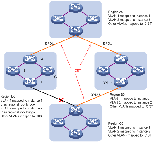
Assume that all the four devices in Figure 47 are running MSTP. This section explains some basic concepts of MSTP based on the figure.
Figure 47 Basic concepts in MSTP
MST region
A multiple spanning tree region (MST region) consists of multiple devices in a switched network and the network segments among them. These devices have the following characteristics:
· All are MSTP-enabled.
· They have the same region name.
· They have the same VLAN-to-MSTI mapping configuration.
· They have the same MSTP revision level configuration.
· They are physically linked with one another.
For example, all the devices in region A0 in Figure 47 have the same MST region configuration:
· The same region name.
· The same VLAN-to-MSTI mapping configuration (VLAN 1 is mapped to MSTI 1, VLAN 2 to MSTI 2, and the rest to the common and internal spanning tree (CIST, or MSTI 0).
· The same MSTP revision level (not shown in the figure).
Multiple MST regions can exist in a switched network. You can assign multiple devices to the same MST region.
VLAN-to-MSTI mapping table
As an attribute of an MST region, the VLAN-to-MSTI mapping table describes the mapping relationships between VLANs and MSTIs. In Figure 47, for example, the VLAN-to-MSTI mapping table of region A0 is: VLAN 1 is mapped to MSTI 1, VLAN 2 to MSTI 2, and the rest to CIST. MSTP achieves load balancing by means of the VLAN-to-MSTI mapping table.
IST
An internal spanning tree (IST) is a spanning tree that runs in an MST region.
ISTs in all MST regions and the common spanning tree (CST) jointly constitute the common and internal spanning tree (CIST) of the entire network. An IST is a section of the CIST. An IST is a special MSTI.
In Figure 47, for example, the CIST has a section in each MST region, and this section is the IST in the respective MST region.
CST
The CST is a single spanning tree that connects all MST regions in a switched network. If you regard each MST region as a "device," the CST is a spanning tree calculated by these devices through STP or RSTP. CSTs are indicated by red lines in Figure 47.
CIST
Jointly constituted by ISTs and the CST, the CIST is a single spanning tree that connects all devices in a switched network.
In Figure 47, for example, the ISTs in all MST regions plus the inter-region CST constitute the CIST of the entire network.
MSTI
Multiple spanning trees can be generated in an MST region through MSTP, one spanning tree being independent of another. Each spanning tree is referred to as a multiple spanning tree instance (MSTI).
In Figure 47, for example, multiple MSTIs can exist in each MST region, each MSTI corresponding to the specified VLANs.
Regional root bridge
The root bridge of the IST or an MSTI within an MST region is the regional root bridge of the IST or the MSTI. Based on the topology, different spanning trees in an MST region may have different regional roots.
For example, in region D0 in Figure 47, the regional root of MSTI 1 is device B, and that of MSTI 2 is device C.
Common root bridge
The common root bridge is the root bridge of the CIST.
In Figure 47, for example, the common root bridge is a device in region A0.
Boundary port
A boundary port is a port that connects an MST region to another MST region, or to a single spanning-tree region running STP, or to a single spanning-tree region running RSTP. It is at the boundary of an MST region.
During MSTP calculation, the role of a boundary port in an MSTI must be consistent with its role in the CIST. However, this is not true with master ports. A master port on MSTIs is a root port on the CIST. For example, in Figure 47, if a device in region A0 is connected to the first port of a device in region D0 and the common root bridge of the entire switched network is located in region A0, the first port of that device in region D0 is the boundary port of region D0.
Port roles
MSTP calculation involves the following port roles:
· Root port—A port responsible for forwarding data to the root bridge.
· Designated port—A port responsible for forwarding data to the downstream network segment or device.
· Master port—A port on the shortest path from the current region to the common root bridge, connecting the MST region to the common root bridge. If the region is seen as a node, the master port is the root port of the region on the CST. The master port is a root port on IST/CIST and still a master port on the other MSTIs.
· Alternate port—The standby port for the root port and the master port. When the root port or master port is blocked, the alternate port becomes the new root port or master port.
· Backup port—The backup port of a designated port. When the designated port is blocked, the backup port becomes a new designated port and starts forwarding data without delay. A loop occurs when two ports of the same MSTP device are interconnected. The device will block either of the two ports, and the backup port is the port to be blocked.
A port can play different roles in different MSTIs.
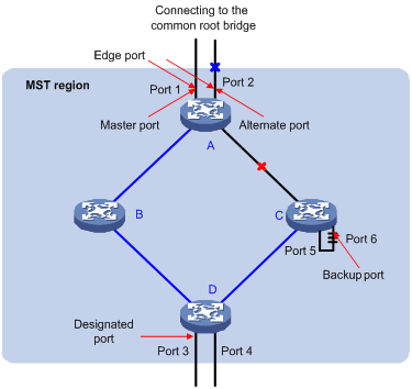
In Figure 48, devices A, B, C, and D constitute an MST region. Port 1 and port 2 of device A are connected to the common root bridge, port 5 and port 6 of device C form a loop, and port 3 and port 4 of Device D are connected downstream to the other MST regions.
Port states
In MSTP, a port can be in one of the following states:
· Forwarding—The port learns MAC addresses and forwards user traffic.
· Learning—The port learns MAC addresses but does not forward user traffic.
· Discarding—The port does not learn MAC addresses or forwards user traffic.
A port can have different port states in different MSTIs. A port state is not exclusively associated with a port role. Table 20 lists the port states supported by each port role. ("√" indicates that the port state is available for the corresponding port role, and "—" indicates that the port state is not available for the corresponding port role.)
Table 20 Ports states supported by different port roles
|
Port state |
Port role |
||||
|
Root port/master port |
Designated port |
Boundary port |
Alternate port |
Backup port |
|
|
Forwarding |
√ |
√ |
√ |
— |
— |
|
Learning |
√ |
√ |
√ |
— |
— |
|
Discarding |
√ |
√ |
√ |
√ |
√ |
How MSTP works
MSTP divides an entire Layer 2 network into multiple MST regions, which are interconnected by a calculated CST. Inside an MST region, multiple spanning trees are calculated, each being an MSTI. Among these MSTIs, MSTI 0 is called the CIST. Similar to RSTP, MSTP uses configuration BPDUs to calculate spanning trees. The only difference between the two protocols is that an MSTP BPDU carries the MSTP configuration on the device from which this BPDU is sent.
CIST calculation
The calculation of a CIST tree is also the process of configuration BPDU comparison. During this process, the device with the highest priority is elected as the root bridge of the CIST. MSTP generates an IST within each MST region through calculation, and, at the same time, MSTP regards each MST region as a single device and generates a CST among these MST regions through calculation. The CST and ISTs constitute the CIST of the entire network.
MSTI calculation
Within an MST region, MSTP generates different MSTIs for different VLANs based on the VLAN-to-MSTI mappings. MSTP performs a separate calculation process, which is similar to spanning tree calculation in STP/RSTP, for each spanning tree. For more information, see "How STP works."
In MSTP, a VLAN packet is forwarded along the following paths:
· Within an MST region, the packet is forwarded along the corresponding MSTI.
· Between two MST regions, the packet is forwarded along the CST.
Implementation of MSTP on devices
MSTP is compatible with STP and RSTP. STP and RSTP protocol packets can be recognized by devices running MSTP and used for spanning tree calculation.
In addition to basic MSTP functions, the device provides the following functions for ease of management:
· Root bridge hold.
· Root bridge backup.
· Root guard.
· BPDU guard.
· TC-BPDU (a message that notifies the device of topology changes) guard.
· Support for the hot swapping of interface boards and switchover of the active and standby main boards.
Protocols and standards
· IEEE 802.1d, Spanning Tree Protocol
· IEEE 802.1w, Rapid Spanning Tree Protocol
· IEEE 802.1s, Multiple Spanning Tree Protocol
Configuration guidelines
When you configure MSTP, follow these guidelines:
· Two devices belong to the same MST region only if they are interconnected through physical links, and share the same region name, the same MSTP revision level, and the same VLAN-to-MSTI mappings.
· If two or more devices have been designated to be root bridges of the same spanning tree instance, MSTP will select the device with the lowest MAC address as the root bridge.
· If the device is not enabled with BPDU guard, when an edge port receives a BPDU from another port, it transits into a non-edge port. To restore its port role as an edge port, you must restart the port.
· Configure ports that are directly connected to terminals as edge ports and enable BPDU guard for them. In this way, these ports can rapidly transit to the forwarding state, and the network security can be ensured.
Recommended MSTP configuration procedure
|
Step |
Remarks |
|
Optional. Configure the MST region-related parameters and VLAN-to-MSTI mappings. By default, the MST region-related parameters adopt the default values, and all VLANs in an MST region are mapped to MSTI 0. |
|
|
Required. Enable STP globally and configure MSTP parameters. By default, STP is disabled globally. All MSTP parameters have default values. |
|
|
Optional. Enable MSTP on a port and configure MSTP parameters. By default, MSTP is enabled on a port, and all MSTP parameters adopt the default values. |
|
|
Optional. Display MSTP information of a port in MSTI 0, the MSTI to which the port belongs, and the path cost and priority of the port. |
Configuring an MST region
1. Select Network > MSTP from the navigation tree.
By default, the Region tab is displayed.
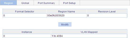
2. Click Modify to enter the page for configuring MST regions.
Figure 50 Configuring an MST region
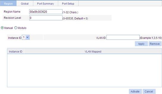
3. Configure the MST region information as described in Table 21, and click Apply.
4. Click Activate.
|
Item |
Description |
|
Region Name |
MST region name. The MST region name is the bridge MAC address of the device by default. |
|
Revision Level |
Revision level of the MST region. |
|
Manual (Instance ID and VLAN ID) |
Manually add VLAN-to-MSTI mappings. Click Apply to add the VLAN-to-MSTI mapping entries to the list. |
|
Modulo |
The device automatically maps 4094 VLANs to the corresponding MSTIs based on the modulo value. |
Configuring MSTP globally
1. Select Network > MSTP from the navigation tree.
2. Click the Global tab to enter the page for configuring MSTP globally.
Figure 51 Configuring MSTP globally
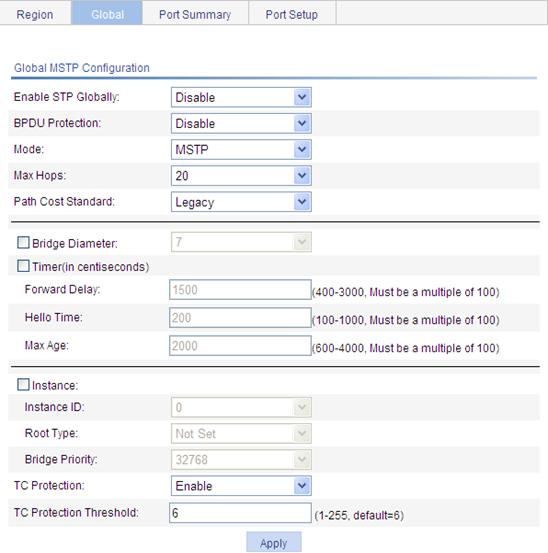
3. Configure the global MSTP configuration as described in Table 22.
4. Click Apply.
|
Item |
Description |
|
Enable STP Globally |
Select whether to enable STP globally. Other MSTP configurations take effect only after you enable STP globally. |
|
BPDU Guard |
Select whether to enable BPDU guard. BPDU guard can protect the device from malicious BPDU attacks, making the network topology stable. |
|
Mode |
Set the operating mode of STP: · STP—Each port on a device sends out STP BPDUs. · RSTP—Each port on a device sends out RSTP BPDUs, and automatically migrates to STP-compatible mode when detecting that it is connected with a device running STP. · MSTP—Each port on a device sends out MSTP BPDUs, and automatically migrates to STP-compatible mode when detecting that it is connected with a device running STP. |
|
Max Hops |
Set the maximum number of hops in an MST region to restrict the region size. The setting can take effect only when it is configured on the regional root bridge. |
|
Path Cost Standard |
Specify the standard for path cost calculation. It can be Legacy, IEEE 802.1D-1998, or IEEE 802.1T. |
|
Bridge Diameter |
Any two stations in a switched network are interconnected through a specific path composed of a series of devices. The bridge diameter (or the network diameter) is the number of devices on the path composed of the most devices. After you set the network diameter, you cannot set the timers. Instead, the device automatically calculates the forward delay, hello time, and max age. When you configure the bridge diameter, follow these guidelines: · The configured network diameter is effective for CIST only, not for MSTIs. · The bridge diameter cannot be configured together with the timers. |
|
Timers |
Configure the timers: · Forward Delay—Set the delay for the root and designated ports to transit to the forwarding state. · Hello Time—Set the interval at which the device sends hello packets to the surrounding devices to make sure the paths are fault-free. · Max Age—Set the maximum length of time a configuration BPDU can be held by the device. When you configure timers, follow these guidelines: · The settings of hello time, forward delay and max age must meet a certain formula. Otherwise, the network topology will not be stable. H3C recommends you to set the network diameter and then have the device automatically calculate the forward delay, hello time, and max age. · The bridge diameter cannot be configured together with the timers. |
|
Instance (Instance ID, Root Type, and Bridge Priority) |
Set the role of the device in the MSTI or the bridge priority of the device, which is one of the factors deciding whether the device can be elected as the root bridge. Role of the device in the MSTI: · Not Set—Not set (you can set the bridge priority of the device when selecting this role) · Primary—Configure the device as the root bridge (you cannot set the bridge priority of the device when selecting this role) · Secondary—Configure the device as a secondary root bridge (you cannot set the bridge priority of the device when selecting this role). |
|
tc-protection |
Select whether to enable TC-BPDU guard. When receiving topology change (TC) BPDUs, the device flushes its forwarding address entries. If someone forges TC-BPDUs to attack the device, the device will receive a large number of TC-BPDUs within a short time and frequently flushes its forwarding address entries. This affects network stability. With the TC-BPDU guard function, you can prevent frequent flushing of forwarding address entries. H3C does not recommend you to disable this function. |
|
tc-protection threshold |
Set the maximum number of immediate forwarding address entry flushes the device can perform within a certain period of time after receiving the first TC-BPDU. |
Configuring MSTP on a port
1. Select Network > MSTP from the navigation tree.
2. Click the Port Setup tab to enter the page for configuring MSTP on ports.
Figure 52 MSTP configuration on a port
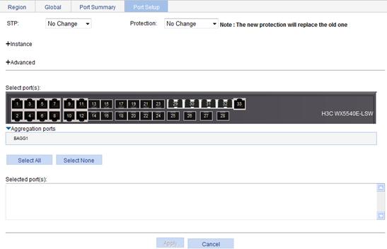
3. Configure MSTP for ports as described in Table 23.
4. Click Apply.
|
Item |
Description |
|
STP |
Select whether to enable STP on the port. |
|
Protection |
Set the type of protection to be enabled on the port: · Not Set—No protection is enabled on the port. · Edged Port, Root Protection, Loop Protection—For more information, see Table 24. |
|
Instance (Instance ID, Port Priority, Auto Path Cost, and Manual Path Cost) |
Set the priority and path cost of the port in the current MSTI: · Priority—The priority of a port is an important factor in determining whether the port can be elected as the root port of a device. If all other conditions are the same, the port with the highest priority will be elected as the root port. On an MSTP-enabled device, a port can have different priorities in different MSTIs, and the same port can play different roles in different MSTIs, so that data of different VLANs can be propagated along different physical paths, implementing per-VLAN load balancing. You can set port priority values based on the actual networking requirements. · Path cost—A parameter related to the rate of a port. On an MSTP-enabled device, a port can have different path costs in different MSTIs. Setting appropriate path costs allows VLAN traffic flows to be forwarded along different physical links, achieving VLAN-based load balancing. The device can automatically calculate the default path cost. Alternatively, you can also manually configure path cost for ports. |
|
Advanced |
·
Point to Point ¡ Auto—Configure the device to automatically detect whether or not the link type of the port is point-to-point. ¡ Force False—The link type for the port is not point-to-point link. ¡ Force True—The link type for the port is point-to-point link. If a port is configured as connecting to a point-to-point link, the setting takes effect for the port in all MSTIs. If the physical link to which the port connects is not a point-to-point link and you force it to be a point-to-point link by configuration, the configuration might incur a temporary loop. ·
Transmit Limit—Configure the maximum number of MSTP packets that can be
sent during each Hello interval. ·
MSTP Mode—Set whether the port migrates to the MSTP mode. |
|
Select port(s) |
Select one or multiple ports on which you want to configure MSTP on the chassis front panel. If aggregate interfaces are configured on the device, the page displays a list of aggregate interfaces below the chassis front panel. You can select aggregate interfaces from this list. |
|
Protection type |
Description |
|
Edged Port |
Set the port as an edge port. Some ports of access layer devices are directly connected to PCs or file servers, which cannot generate BPDUs. You can set these ports as edge ports to achieve fast transition for these ports. H3C recommends that you enable the BPDU guard function in conjunction with the edged port function to avoid network topology changes when the edge ports receive configuration BPDUs. |
|
Root Protection |
Enable the root guard function. Configuration errors or attacks may result in configuration BPDUs with their priorities higher than that of a root bridge, which causes a new root bridge to be elected and network topology change to occur. The root guard function is used to address such a problem. |
|
Loop Protection |
Enable the loop guard function. By keeping receiving BPDUs from the upstream device, a device can maintain the state of the root port and other blocked ports. These BPDUs may get lost because of network congestion or unidirectional link failures. The device will re-elect a root port, and blocked ports may transit to the forwarding state, causing loops in the network. The loop guard function is used to address such a problem. |
Displaying MSTP information of a port
1. Select Network > MSTP from the navigation tree.
2. Click the Port Summary.
3. Select a port (for example, GigabitEthernet 1/0/16) on the chassis front panel.
If you have configured aggregate interfaces on the device, the page displays a list of aggregate interfaces below the chassis front panel. You can select aggregate interfaces from this list. The lower part of the page displays the MSTP information of the port in MSTI 0 (when STP is enabled globally) or the STP status and statistics (when STP is not enabled globally), the MSTI to which the port belongs, and the path cost and priority of the port in the MSTI.
Figure 53 The port summary tab
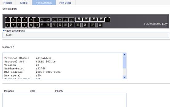
|
Field |
Description |
|
[FORWARDING] |
The port is in forwarding state, so the port learns MAC addresses and forwards user traffic. |
|
[LEARNING] |
The port is in learning state, so the port learns MAC addresses but does not forward user traffic. |
|
[DISCARDING] |
The port is in discarding state, so the port does not learn MAC addresses or forward user traffic. |
|
[DOWN] |
The port is down. |
|
Port Protocol |
Indicates whether STP is enabled on the port. |
|
Port Role |
Role of the port, which can be Alternate, Backup, Root, Designated, Master, or Disabled. |
|
Port Priority |
Priority of the port. |
|
Port Cost(Legacy) |
Path cost of the port. The field in the bracket indicates the standard used for port path cost calculation, which can be legacy, dot1d-1998, or dot1t. Config indicates the configured value, and Active indicates the actual value. |
|
Desg. Bridge/Port |
Designated bridge ID and port ID of the port. The port ID displayed is insignificant for a port that does not support port priority. |
|
Port Edged |
Indicates whether the port is an edge port: · Config—Indicates the configured value. · Active—Indicates the actual value. |
|
Point-to-point |
Indicates whether the port is connected to a point-to-point link: · Config—Indicates the configured value. · Active—Indicates the actual value. |
|
Transmit Limit |
Maximum number of packets sent within each Hello time. |
|
Protection Type |
Protection type on the port: · Root—Root guard. · Loop—Loop guard. · BPDU—BPDU guard. · None—No protection. |
|
MST BPDU Format |
Format of the MST BPDUs that the port can send, which can be legacy or 802.1s. Config indicates the configured value, and Active indicates the actual value. |
|
Port Config- Digest-Snooping |
Indicates whether digest snooping is enabled on the port. |
|
Rapid transition |
Indicates whether the current port rapidly transitions to the forwarding state. |
|
Num of Vlans Mapped |
Number of VLANs mapped to the current MSTI. |
|
PortTimes |
Major parameters for the port: · Hello—Hello timer. · MaxAge—Max Age timer. · FWDly—Forward delay timer. · MsgAge—Message Age timer. · Remain Hop—Remaining hops. |
|
BPDU Sent |
Statistics on sent BPDUs. |
|
BPDU Received |
Statistics on received BPDUs. |
|
Protocol Status |
Indicates whether MSTP is enabled. |
|
Protocol Std. |
MSTP standard. |
|
Version |
MSTP version. |
|
CIST Bridge-Prio. |
Priority of the current device in the CIST. |
|
MAC address |
MAC address of the current device. |
|
Max age(s) |
Maximum age of a configuration BPDU. |
|
Forward delay(s) |
Port state transition delay, in seconds. |
|
Hello time(s) |
Configuration BPDU transmission interval, in seconds. |
|
Max hops |
Maximum hops of the current MST region. |
MSTP configuration example
Network requirements
As shown in Figure 54, configure MSTP so that:
· All devices on the network are in the same MST region.
· Packets of VLAN 10, VLAN 20, VLAN 30, and VLAN 40 are forwarded along MSTI 1, MSTI 2, MSTI 3, and MSTI 0, respectively.
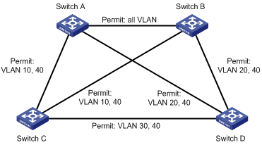
"Permit:" next to a link in the figure is followed by the VLANs the packets of which are permitted to pass this link.
Configuring Switch A
1. Configure an MST region:
a. Select Network > MSTP from the navigation tree.
By default, the Region tab is displayed.
b. Click the Modify button to enter the page for configuring MST regions.
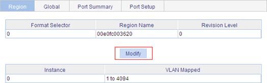
c. Set the region name to example.
d. Set the revision level to 0.
e. Select the Manual option.
f. Select 1 in the Instance ID list.
g. Set the VLAN ID to 10.
h. Click Apply to map VLAN 10 to MSTI 1 and add the VLAN-to-MSTI mapping entry to the VLAN-to-MSTI mapping list.
i. Repeat the preceding three steps to map VLAN 20 to MSTI 2 and VLAN 30 to MSTI 3 and add the VLAN-to-MSTI mapping entries to the VLAN-to-MSTI mapping list.
j. Click Activate.
Figure 56 Configuring an MST region
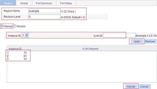
2. Configure MSTP globally:
a. Select Network > MSTP from the navigation tree.
b. Click the Global tab to enter the page for configuring MSTP globally.
c. Select Enable in the Enable STP Globally list.
d. Select MSTP in the Mode list.
e. Select the box before Instance.
f. Set the Instance ID field to 1.
g. Set the Root Type field to Primary.
h. Click Apply.
Figure 57 Configuring MSTP globally (on Switch A)
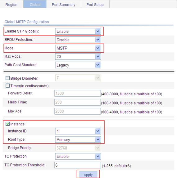
Configuring Switch B
1. Configure an MST region. (The procedure here is the same as that of configuring an MST region on Switch A.)
2. Configure MSTP globally:
a. Select Network > MSTP from the navigation tree.
b. Click the Global tab to enter the page for configuring MSTP globally.
c. Select Enable from the Enable STP Globally list.
d. Select MSTP from the Mode list.
e. Select the box before Instance.
f. Set the Instance ID field to 2.
g. Set the Root Type field to Primary.
h. Click Apply.
Configuring Switch C
1. Configure an MST region. (The procedure here is the same as that of configuring an MST region on Switch A.)
2. Configure MSTP globally:
a. Select Network > MSTP from the navigation tree.
b. Click Global to enter the page for configuring MSTP globally.
c. Select Enable from the Enable STP Globally list.
d. Select MSTP from the Mode list.
e. Select the box before Instance.
f. Set the Instance ID field to 3.
g. Set the Root Type field to Primary.
h. Click Apply.
Configuring Switch D
1. Configure an MST region. The procedure is the same as that of configuring an MST region on Switch A.
2. Configure MSTP globally:
a. Select Network > MSTP from the navigation tree.
b. Click Global to enter the page for configuring MSTP globally.
c. Select Enable from the Enable STP Globally list.
d. Select MSTP from the Mode list.
e. Click Apply.
Figure 58 Configuring MSTP globally (on Switch D)
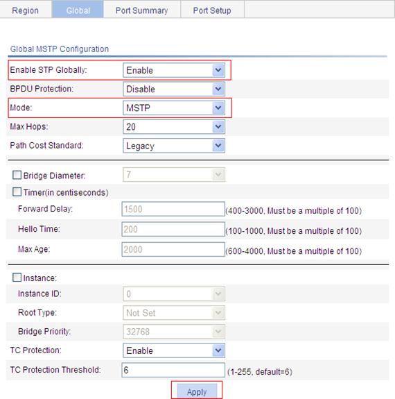
Overview
Link aggregation aggregates multiple physical Ethernet ports into one logical link, also called an aggregation group.
It allows you to increase bandwidth by distributing traffic across the member ports in the aggregation group. In addition, it provides reliable connectivity because these member ports can dynamically back up each other.
Basic concepts of link aggregation
Aggregate interface
An aggregate interface is a logical Layer 2 or Layer 3 aggregate interface.
Aggregation group
An aggregation group is a collection of Ethernet interfaces. When you create an aggregate interface, an aggregation group numbered the same is automatically created, depending on the following aggregate interface types:
· If the aggregate interface is a Layer 2 interface, a Layer 2 aggregation group is created. You can assign only Layer 2 Ethernet interfaces to the group.
· If the aggregate interface is a Layer 3 interface, a Layer 3 aggregation group is created. You can assign only Layer 3 Ethernet interfaces to the group.
States of the member ports in an aggregation group
A member port in an aggregation group can be in one of the following states:
· Selected—A Selected port can forward user traffic.
· Unselected—An Unselected port cannot forward user traffic.
The rate of an aggregate interface is the sum of the selected member ports' rates. The duplex mode of an aggregate interface is consistent with that of the selected member ports. All selected member ports use the same duplex mode.
For information about how to determine the state of a member port, see "Static aggregation mode" and "Dynamic aggregation mode."
LACP protocol
The Link Aggregation Control Protocol (LACP) is defined in IEEE 802.3ad. It uses LACPDUs for information exchange between LACP-enabled devices.
LACP is automatically enabled on interfaces in a dynamic aggregation group. For information about dynamic aggregation groups, see "Dynamic aggregation mode." An LACP-enabled interface sends LACPDUs to notify the remote system (the partner) of its system LACP priority, system MAC address, LACP port priority, port number, and operational key. Upon receiving an LACPDU, the partner compares the received information with the information received on other interfaces to determine the interfaces that can operate as Selected interfaces. This allows the two systems to reach an agreement on which link aggregation member ports should be placed in Selected state.
Operational key
When aggregating ports, link aggregation control automatically assigns each port an operational key based on port attributes, including the port rate, duplex mode and link state configuration.
In an aggregation group, all Selected ports are assigned the same operational key.
Class-two configurations
The contents of class-two configurations are listed in Table 26. In an aggregation group, a member port different from the aggregate interface in the class-two configurations cannot be a Selected port.
Table 26 Class-two configurations
|
Type |
Considerations |
|
Port isolation |
Whether a port has joined an isolation group, and the isolation group to which the port belongs. |
|
QinQ |
QinQ enable state (enable/disable), TPID values in VLAN tags, outer VLAN tags to be added, inner-to-outer VLAN priority mappings, inner-to-outer VLAN tag mappings, inner VLAN ID substitution mappings. |
|
VLAN |
Permitted VLAN IDs, default VLAN, link type (trunk, hybrid, or access), IP subnet-based VLAN configuration, protocol-based VLAN configuration, tag mode. |
|
MAC address learning |
MAC address learning capability, MAC address learning limit, forwarding of frames with unknown destination MAC addresses after the upper limit of the MAC address table is reached. |
Some configurations are called class-one configurations. Such configurations, for example, MSTP, can be configured on aggregate interfaces and member ports but are not considered during operational key calculation.
The change of a class-two configuration setting may affect the select state of link aggregation member ports and the ongoing service. To prevent unconsidered change, a message warning of the hazard will be displayed when you attempt to change a class-two setting, upon which you can decide whether to continue your change operation.
Link aggregation modes
Depending on the link aggregation procedure, link aggregation operates in one of the following modes:
Static aggregation mode
LACP is disabled on the member ports in a static aggregation group. In a static aggregation group, the system sets a port to Selected or Unselected state by the following rules:
· The system selects a port as the reference port from the ports that are in up state and with the same class-two configurations as the corresponding aggregate interface. These ports are selected in the order of full duplex/high speed, full duplex/low speed, half duplex/high speed, and half duplex/low speed, with full duplex/high speed being the most preferred. If two ports with the same duplex mode/speed pair are present, the one with the lower port number wins.
· The system considers the ports in up state with the same port attributes and class-two configurations as the reference port as candidate selected ports, and set all others in Unselected state.
· Static aggregation limits the number of Selected ports in an aggregation group. When the number of the candidate selected ports is under the limit, all the candidate selected ports become Selected ports. When the limit is exceeded, set the candidate selected ports with smaller port numbers in Selected state and those with greater port numbers in Unselected state.
· If all the member ports are down, the system sets their states to Unselected.
A port that joins the aggregation group after the limit on the number of Selected ports has been reached will not be placed in Selected state even if it should be in normal cases. This can prevent the ongoing traffic on the current Selected ports from being interrupted. You should avoid the situation however, as this may cause the Selected/Unselected state of a port to change after a reboot.
Dynamic aggregation mode
LACP is enabled on member ports in a dynamic aggregation group.
In a dynamic aggregation group,
· A Selected port can receive and transmit LACPDUs.
· An Unselected port can receive and send LACPDUs only if it is up and with the same configurations as those on the aggregate interface.
In a dynamic aggregation group, the local system (the actor) negotiates with the remote system (the partner) to determine the port state based on the port IDs on the end with the preferred system ID. In this way, the system sets the ports to Selected or Unselected state. The following negotiation procedure applies:
1. The system compares the system ID (comprising the system LACP priority and the system MAC address) of the actor with that of the partner. The system with the lower LACP priority wins. If they are the same, compare the system MAC addresses. The system with the smaller MAC address wins.
2. The system compares the port IDs of the ports on the system with the smaller system ID. A port ID comprises a port LACP priority and a port number. First, compare the port LACP priorities. The port with the lower LACP priority wins. If two ports are with the same LACP priority, compare their port numbers. The port with the smaller port number is selected as the reference port.
3. If a port in up state is with the same port attributes and class-two configuration as the reference port, and the peer port of the port is with the same port attributes and class-two configurations as the peer port of the reference port, the system considers the port as a candidate selected port. Otherwise, the system sets the port to the Unselected state.
4. The number of Selected ports that an aggregation group can contain is limited. When the number of candidate selected ports is under the limit, all the candidate selected ports are set to Selected state. When the limit is exceeded, the system selects the candidate selected ports with smaller port IDs as the Selected ports, and set other candidate selected ports to Unselected state. At the same time, the peer device, being aware of the changes, also changes the state of its ports.
Guidelines
The following guidelines apply to static and dynamic aggregation modes:
· In an aggregation group, the port to be a Selected port must be the same as the reference port in port attributes, and class-two configurations. To keep these configurations consistent, you should configure the port manually.
· Changing a port attribute or class-two configuration setting of a port might cause the select state of the port and other member ports to change and affects services. H3C recommends that you do that with caution.
Load sharing mode of an aggregation group
A link aggregation groups operates in load sharing aggregation mode or non-load sharing mode.
The system sets the load sharing mode of an aggregation group using the following guidelines:
· When hardware resources are available, a link aggregation group with at least two Selected ports operates in load sharing mode.
· When the number of created aggregation groups reaches the upper threshold, all new link aggregation groups operate in non-load sharing mode.
· A load-sharing aggregation group contains at least one Selected port, but a non-load-sharing aggregation group can only have one Selected port at most.
· After hardware resources become depleted, all new link aggregation groups operate in non-load sharing mode. They will not perform load sharing even after resources become available again for example after some aggregation groups are removed. To have them perform load sharing, you can re-enable their corresponding aggregation interfaces by shutting down and then bringing up the interfaces.
Configuration guidelines
Follow these guidelines when you configure a link aggregation group:
· In an aggregation group, the port to be a Selected port must be the same as the reference port in port attributes, and class-two configurations. To keep these configurations consistent, you should configure the port manually.
· Reference port—Select a port as the reference port from the ports that are in up state and with the same class-two configurations as the corresponding aggregate interface. The selection is performed in the following order: full duplex/high speed, full duplex/low speed, half duplex/high speed, and half duplex/low speed, with full duplex/high speed being the most preferred. If two ports with the same duplex mode/speed pair are present, the one with the lower port number wins.
· Port attribute configuration includes the configuration of the port rate, duplex mode, and link state. For more information about class-two configurations, see "Class-two configurations."
· To guarantee a successful static aggregation, make sure the ports at the two ends of each link to be aggregated are consistent in Selected/Unselected state. To guarantee a successful dynamic aggregation, make sure the peer ports of the ports aggregated at one end are also aggregated. The two ends can automatically negotiate the Selected state of the ports.
· These types of ports cannot be assigned to Layer 2 aggregate groups: RRPP-enabled ports, MAC address authentication-enabled ports, port security-enabled ports, packet filtering-enabled ports, Ethernet frame filtering-enabled ports, IP source guard-enabled ports, and 802.1X-enabled ports.
· You may assign to an aggregation group these types of ports: the monitor ports of port mirroring groups, ports configured with static MAC addresses, or ports configured with MAC address learning limit.
· Removing a Layer 2 aggregate interface also removes the corresponding aggregation group. Meanwhile, the member ports of the aggregation group, if any, leave the aggregation group.
· When a load-sharing aggregation group becomes a non-load-sharing aggregation group because of insufficient load sharing resources, one of the following problems might have occurred:
¡ The number of Selected ports of the actor is inconsistent with that of the partner, which might result in incorrect traffic forwarding.
¡ The peer port of a Selected port is an Unselected port, which might result anomalies in upper-layer protocol and traffic forwarding.
Consider the situation fully when making configuration.
Recommended link aggregation and LACP configuration procedures
Recommended static aggregation group configuration procedure
|
Step |
Remarks |
|
Required. Create a static aggregate interface and configure member ports for the static aggregation group automatically created by the system when you create the aggregate interface. By default, no link aggregation group exists. |
|
|
Optional. Perform this task to view detailed information of an existing aggregation group. |
Recommended dynamic aggregation group configuration procedure
|
Step |
Remarks |
|
Required. Create a dynamic aggregate interface and configure member ports for the dynamic aggregation group automatically created by the system when you create the aggregate interface. LACP is enabled automatically on all the member ports. By default, no link aggregation group exists. |
|
|
Optional. Perform this task to view detailed information of an existing aggregation group. |
|
|
Optional. Perform the task to set LACP priority for the local system and link aggregation member ports. Changes of LACP priorities affect the Selected/Unselected state of link aggregation member ports. The default port LACP priority and system LACP priority are both 32768. |
|
|
Optional. Perform the task to view detailed information of LACP-enabled ports and the corresponding remote (partner) ports. |
Creating a link aggregation group
1. Select Network > Link Aggregation from the navigation tree.
2. Click Create.
Figure 59 Creating a link aggregation group

3. Configure a link aggregation group as described in Table 27.
4. Click Apply.
|
Item |
Description |
|
Enter Link Aggregation Interface ID |
Assign an ID to the link aggregation group to be created. You can view the result in the Summary area at the bottom of the page. |
|
Specify Interface Type |
Set the type of the link aggregation interface to be created: · Static (LACP Disabled) · Dynamic (LACP Enabled) |
|
Select port(s) for the link aggregation interface |
Select one or multiple ports to be assigned to the link aggregation group from the chassis front panel. You can view the result in the Summary area at the bottom of the page. |
Displaying information of an aggregate interface
1. Select Network > Link Aggregation from the navigation tree.
The Summary tab is displayed by default. The list on the upper part of the page displays information about all the aggregate interfaces.
2. Select an aggregate interface from the list.
The list on the lower part of the page displays the detailed information about the member ports of the corresponding link aggregation group.
Figure 60 Displaying information of an aggregate interface
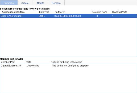
Table 28 Field description
|
Field |
Description |
|
Aggregation interface |
Type and ID of the aggregate interface. Bridge-Aggregation indicates a Layer 2 aggregate interface. |
|
Link Type |
Type of the aggregate interface, which can be static or dynamic. |
|
Partner ID |
ID of the remote device, including its LACP priority and MAC address. |
|
Selected Ports |
Number of Selected ports in each link aggregation group (Only Selected ports can transmit and receive user data). |
|
Standby Ports |
Number of Unselected ports in each link aggregation group (Unselected ports cannot transmit or receive user data). |
|
Member Port |
A member port of the link aggregation group corresponding to the selected aggregate interface. |
|
State |
Select state of a member port: Selected or Unselected. |
|
Reason for being Unselected |
Reason why the state of a member port is Unselected. For a selected member port, this field is displayed as a hyphen (-). |
Setting LACP priority
1. Select Network > LACP from the navigation tree.
2. Click Setup.
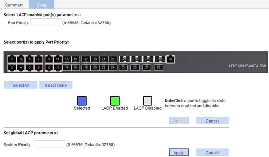
3. In the Set LACP enabled port(s) parameters area, set the port priority, and select the ports in the chassis front panel.
4. Click Apply in the area.
|
Item |
Description |
|
Port Priority |
Set a port LACP priority. |
|
Select port(s) to apply Port Priority |
Select the ports where the port LACP priority you set will apply on the chassis front panel. You can set LACP priority not only on LACP-enabled ports but also on LACP-disabled ports. |
5. In the Set global LACP parameters area, set the system priority.
6. Click Apply in the area.
Displaying information of LACP-enabled ports
1. Select Network > LACP from the navigation tree.
The Summary tab is displayed by default. The upper part of the page displays a list of all LACP-enabled ports on the device and information about them. Table 30 describes the fields.
2. Select a port on the port list.
3. Click View Details.
Detailed information about the peer port appears on the lower part of the page. Table 31 describes the fields.
Figure 62 Displaying the information of LACP-enabled ports
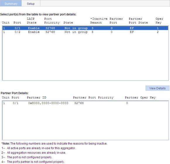
|
Field |
Description |
|
Unit |
ID of a device in an IRF. |
|
Port |
Port where LACP is enabled. |
|
LACP State |
State of LACP on the port. |
|
Port Priority |
LACP priority of the port. |
|
State |
Active state of the port. If a port is Selected, its state is active and the ID of the aggregation group it belongs to will be displayed. |
|
Inactive Reason |
Reason code indicating why a port is inactive (or Unselected) for receiving/transmitting user data. For the meanings of the reason codes, see the bottom of the page shown in Figure 62. |
|
Partner Port |
Name of the peer port. |
|
Partner Port State |
State information of the peer port: · A—Indicates that LACP is enabled. · B—Indicates that LACP short timeout has occurred. If B does not appear, it —Indicates that LACP long timeout has occurred. · C—Indicates that the link is considered aggregatable by the sending system. · D—Indicates that the link is considered as synchronized by the sending system. · E—Indicates that the sending system considers that collection of incoming frames is enabled on the link. · F—Indicates that the sending system considers that distribution of outgoing frames is enabled on the link. · G—Indicates that the receive state machine of the sending system is using the default operational partner information. · H—Indicates that the receive state machine of the sending system is in expired state. |
|
Oper Key |
Operational key of the local port. |
Table 31 Field description
|
Field |
Description |
|
Unit |
Number of the remote system. |
|
Port |
Name of the remote port. |
|
Partner ID |
LACP priority and MAC address of the remote system. |
|
Partner Port Priority |
LACP priority of the remote port. |
|
Partner Oper Key |
Operational key of the remote port. |
Link aggregation and LACP configuration example
Network requirements
As shown in Figure 63, aggregate the ports on each device to form a link aggregation group, balancing incoming/outgoing traffic across the member ports.
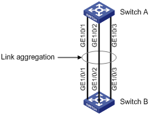
You can create a static or dynamic link aggregation group to achieve load balancing.
Method 1: Create static link aggregation group 1
1. Select Network > Link Aggregation from the navigation tree.
2. Click Create.
3. Configure static link aggregation group 1:
a. Enter link aggregation interface ID 1.
b. Select the Static (LACP Disabled) option for the aggregate interface type.
c. Select GigabitEthernet 1/0/1, GigabitEthernet 1/0/2, and GigabitEthernet 1/0/3 on the chassis front panel.
4. Click Apply.
Figure 64 Creating static link aggregation group 1

Method 2: Create dynamic link aggregation group 1
1. Select Network > Link Aggregation from the navigation tree.
2. Click Create.
3. Configure dynamic aggregation group 1:
a. Enter link aggregation interface ID 1.
b. Select the Dynamic (LACP Enabled) option for aggregate interface type.
c. Select GigabitEthernet 1/0/1, GigabitEthernet 1/0/2, and GigabitEthernet 1/0/3 on the chassis front panel.
4. Click Apply.
Figure 65 Creating dynamic link aggregation group 1
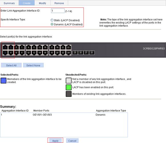
Overview
In a heterogeneous network, a standard configuration exchange platform makes sure different types of network devices from different vendors can discover one another, and exchange configuration for the sake of interoperability and management.
The IETF drafted the Link Layer Discovery Protocol (LLDP) in IEEE 802.1AB. The protocol operates on the data link layer to exchange device information between directly connected devices. With LLDP, a device sends local device information, including its major functions, management IP address, device ID, and port ID, as TLV (type, length, and value) triplets in LLDP Data Units (LLDPDUs) to the directly connected devices. At the same time, the device stores the device information received in LLDPDUs sent from the LLDP neighbors in a standard MIB. LLDP enables a network management system to quickly detect and identify Layer 2 network topology changes.
Basic concepts
LLDPDU formats
LLDP sends device information in LLDP data units (LLDPDUs). LLDPDUs are encapsulated in Ethernet II or SNAP frames.
· LLDPDUs encapsulated in Ethernet II
Figure 66 LLDPDU encapsulated in Ethernet II
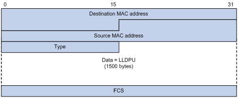
Table 32 Description of the fields in an Ethernet II encapsulated LLDPDU
|
Field |
Description |
|
Destination MAC address |
MAC address to which the LLDPDU is advertised. It is fixed to 0x0180-C200-000E, a multicast MAC address. |
|
Source MAC address |
MAC address of the sending port. |
|
Type |
Ethernet type for the upper layer protocol. It is 0x88CC for LLDP. |
|
Data |
LLDP data. |
|
FCS |
Frame check sequence, a 32-bit CRC value used to determine the validity of the received Ethernet frame. |
· LLDPDUs encapsulated in SNAP
Figure 67 LLDPDU encapsulated in SNAP
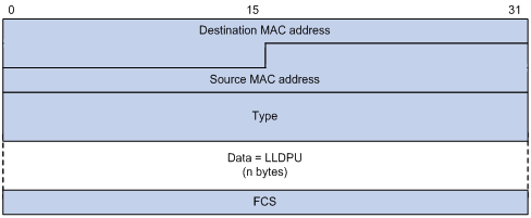
Table 33 Description of the fields in a SNAP-encapsulated LLDPDU
|
Field |
Description |
|
Destination MAC address |
MAC address to which the LLDPDU is advertised. It is fixed to 0x0180-C200-000E, a multicast MAC address. |
|
Source MAC address |
MAC address of the sending port. If the port does not have a MAC address, the MAC address of the sending bridge is used. |
|
Type |
SNAP-encoded LLDP Ethernet type for the upper layer protocol. It is 0xAAAA-0300-0000-88CC for LLDP. |
|
Data |
LLDP data unit. |
|
FCS |
Frame check sequence, a 32-bit CRC value used to determine the validity of the received Ethernet frame. |
LLDPDUs
LLDP uses LLDPDUs to exchange information. An LLDPDU comprises multiple TLV sequences, each carrying a type of device information, as shown in Figure 68.
Figure 68 LLDPDU encapsulation format
![]()
An LLDPDU can carry up 28 types of TLVs, of which the chassis ID TLV, port ID TLV, TTL TLV, and end of LLDPDU TLV are mandatory TLVs that must be carried and other TLVs are optional.
TLVs
TLVs are type, length, and value sequences that carry information elements, where the type field identifies the type of information, the length field indicates the length of the information field in octets, and the value field contains the information itself.
LLDPDU TLVs include the following categories:
· Basic management TLVs.
· Organizationally (IEEE 802.1 and IEEE 802.3) specific TLVs.
· LLDP-MED (media endpoint discovery) TLVs.
Basic management TLVs are essential to device management. Organizationally specific TLVs and LLDP-MED TLVs are used for improved device management. They are defined by standardization or other organizations and are optional to LLDPDUs.
· Basic management TLVs
Table 34 lists the basic management TLV types in use. Some of them must be included in every LLDPDU.
|
Type |
Description |
Remarks |
|
Chassis ID |
Specifies the bridge MAC address of the sending device. |
Mandatory. |
|
Port ID |
Specifies the ID of the sending port. If LLDP-MED TLVs are included in the LLDPDU, the port ID TLV carries the MAC address of the sending port or the bridge MAC in case the port does not have a MAC address. If no LLDP-MED TLVs are included, the port ID TLV carries the port name. |
|
|
Time to Live |
Specifies the life of the transmitted information on the receiving device. |
|
|
End of LLDPDU |
Marks the end of the TLV sequence in the LLDPDU. |
|
|
Port Description |
Specifies the port description of the sending port. |
Optional. |
|
System Name |
Specifies the assigned name of the sending device. |
|
|
System Description |
Specifies the description of the sending device. |
|
|
System Capabilities |
Identifies the primary functions of the sending device and the primary functions that have been enabled. |
|
|
Management Address |
Specifies the management address used to reach higher level entities to assist discovery by network management, and the interface number and OID associated with the address. |
· IEEE 802.1 organizationally specific TLVs
Table 35 IEEE 802.1 organizationally specific TLVs
|
Type |
Description |
|
Port VLAN ID |
Specifies the port's VLAN identifier (PVID). An LLDPDU carries only one TLV of this type. |
|
Port And Protocol VLAN ID |
Indicates whether the device supports protocol VLANs and, if so, what VLAN IDs these protocols will be associated with. An LLDPDU can carry multiple different TLVs of this type. |
|
VLAN Name |
Specifies the textual name of any VLAN to which the port belongs. An LLDPDU can carry multiple different TLVs of this type. |
|
Protocol Identity |
Indicates protocols supported on the port. An LLDPDU can carry multiple different TLVs of this type. |
|
DCBX |
Data center bridging exchange protocol. |
H3C devices only support receiving protocol identity TLVs.
Layer 3 Ethernet interfaces do not support IEEE 802.1 organizationally specific TLVs.
· IEEE 802.3 organizationally specific TLVs
Table 36 IEEE 802.3 organizationally specific TLVs
|
Type |
Description |
|
MAC/PHY Configuration/Status |
Contains the rate and duplex capabilities of the sending port, support for auto negotiation, enabling status of auto negotiation, and the current rate and duplex mode. |
|
Power Via MDI |
Contains the power supply capability of the port, including the PoE type, which can be PSE or PD, PoE mode, whether PSE power supply is supported, whether PSE power supply is enabled, and whether the PoE mode is controllable. |
|
Link Aggregation |
Indicates the support of the port for link aggregation, the aggregation capability of the port, and the aggregation status (or whether the link is in an aggregation). |
|
Maximum Frame Size |
Indicates the supported maximum frame size. It is now the MTU of the port. |
|
Power Stateful Control |
Indicates the power state control configured on the sending port, including the power type of the PSE/PD, PoE sourcing/receiving priority, and PoE sourcing/receiving power. |
The Power Stateful Control TLV is defined in IEEE P802.3at D1.0. The later versions no longer support this TLV. H3C devices send this type of TLVs only after receiving them.
· LLDP-MED TLVs
LLDP-MED TLVs provide multiple advanced applications for VoIP, such as basic configuration, network policy configuration, and address and directory management. LLDP-MED TLVs satisfy the voice device vendors' requirements for cost effectiveness, ease of deployment, and ease of management. In addition, LLDP-MED TLVs make deploying voice devices in Ethernet easier. LLDP-MED TLVs are shown in Table 37.
|
Type |
Description |
|
LLDP-MED Capabilities |
Allows a network device to advertise the LLDP-MED TLVs that it supports. |
|
Network Policy |
Allows a network device or terminal device to advertise the VLAN ID of the specific port, the VLAN type, and the Layer 2 and Layer 3 priorities for specific applications. |
|
Extended Power-via-MDI |
Allows a network device or terminal device to advertise power supply capability. This TLV is an extension of the Power Via MDI TLV. |
|
Hardware Revision |
Allows a terminal device to advertise its hardware version. |
|
Firmware Revision |
Allows a terminal device to advertise its firmware version. |
|
Software Revision |
Allows a terminal device to advertise its software version. |
|
Serial Number |
Allows a terminal device to advertise its serial number. |
|
Manufacturer Name |
Allows a terminal device to advertise its vendor name. |
|
Model Name |
Allows a terminal device to advertise its model name. |
|
Asset ID |
Allows a terminal device to advertise its asset ID. The typical case is that the user specifies the asset ID for the endpoint to help directory management and asset tracking. |
|
Location Identification |
Allows a network device to advertise the appropriate location identifier information for a terminal device to use in the context of location-based applications. |
For more information about LLDPDU TLVs, see the IEEE standard (LLDP) 802.1AB-2005 and the LLDP-MED standard (ANSI/TIA-1057).
Management address
The management address of a device is used by the network management system to identify and manage the device for topology maintenance and network management. The management address is encapsulated in the management address TLV.
Operating modes of LLDP
LLDP can operate in one of the following modes:
· TxRx mode—A port in this mode sends and receives LLDPDUs.
· Tx mode—A port in this mode only sends LLDPDUs.
· Rx mode—A port in this mode only receives LLDPDUs.
· Disable mode—A port in this mode does not send or receive LLDPDUs.
Each time the LLDP operating mode of a port changes, its LLDP protocol state machine re-initializes. To prevent LLDP from being initialized too frequently at times of frequent operating mode change, an initialization delay, which is user configurable, is introduced. With this delay mechanism, a port must wait for the specified interval before it can initialize LLDP after the LLDP operating mode changes.
How LLDP works
Transmitting LLDPDUs
An LLDP-enabled port operating in TxRx mode or Tx mode sends LLDPDUs to its directly connected devices both periodically and when the local configuration changes. To prevent the network from being overwhelmed by LLDPDUs at times of frequent local device information change, an interval is introduced between two successive LLDPDUs.
This interval is shortened to 1 second in either of the following cases:
· A new neighbor is discovered. A new LLDPDU is received carrying device information new to the local device.
· The LLDP operating mode of the port changes from Disable/Rx to TxRx or Tx.
This is the fast sending mechanism of LLDP. With this mechanism, a specific number of LLDPDUs are sent successively at the 1-second interval to help LLDP neighbors discover the local device as soon as possible. Then, the normal LLDPDU transit interval resumes.
Receiving LLDPDUs
An LLDP-enabled port operating in TxRx mode or Rx mode checks the TLVs carried in every LLDPDU it receives for validity violation. If valid, the information is saved and an aging timer is set for it based on the TTL TLV carried in the LLDPDU. If the TTL TLV is zero, the information is aged out immediately.
Compatibility of LLDP with CDP
You must enable CDP compatibility for your device to work with Cisco IP phones.
As your LLDP-enabled device cannot recognize Cisco Discovery Protocol (CDP) packets, it does not respond to the requests of Cisco IP phones for the voice VLAN ID configured on the device. This can cause a requesting Cisco IP phone to send voice traffic untagged to your device, disabling your device to differentiate voice traffic from other types of traffic.
CDP compatibility enables LLDP on your device to receive and recognize CDP packets from Cisco IP phones and respond with CDP packets carrying the voice VLAN configuration TLV for the IP phones to configure the voice VLAN automatically. The voice traffic is confined in the configured voice VLAN to be differentiated from other types of traffic.
CDP-compatible LLDP operates in one of the follows modes:
· TxRx—CDP packets can be transmitted and received.
· Disable—CDP packets can neither be transmitted nor be received.
Protocols and standards
· IEEE 802.1AB-2005, Station and Media Access Control Connectivity Discovery
· ANSI/TIA-1057, Link Layer Discovery Protocol for Media Endpoint Devices
LLDP configuration guidelines
When you configure LLDP, follow these guidelines:
· To make LLDP take effect, enable it both globally and at port level.
· To advertise LLDP-MED TLVs other than the LLDP-MED capabilities TLV, include the LLDP-MED capabilities TLV.
· To remove the LLDP-MED capabilities TLV, remove all other LLDP-MED TLVs.
· To remove the MAC/PHY configuration TLV, remove the LLDP-MED capabilities set TLV first.
· When the advertising of LLDP-MED capabilities TLV and MAC/PHY configuration/status TLV is disabled, if the LLDP-MED capabilities set TLV is included, the MAC/PHY configuration/status TLV is included automatically.
· When you configure LLDP settings for ports in batch, if you do not set the TLVs, each port uses its own TLV settings.
Recommended LLDP configuration procedure
|
Step |
Remarks |
|
Optional. By default, LLDP is enabled on ports. Make sure LLDP is also enabled globally, because LLDP can work on a port only when it is enabled both globally and on the port. |
|
|
Optional. LLDP settings include LLDP operating mode, packet encapsulation, CDP compatibility, device information polling, trapping, and advertisable TLVs. By default: · The LLDP operating mode is TxRx. · The encapsulation format is Ethernet II. · CDP compatibility is disabled. · Device information polling and trapping are disabled. · All TLVs except the Location Identification TLV are advertised. |
|
|
Required. By default, global LLDP is disabled. To enable LLDP to work on a port, enable LLDP both globally and on the port. |
|
|
Optional. You can display the local LLDP information, neighbor information, statistics, and status information of a port, where: · The local LLDP information refers to the TLVs to be advertised by the local device to neighbors. · The neighbor information refers to the TLVs received from neighbors. |
|
|
Optional. You can display the local global LLDP information and statistics. |
|
|
6. Displaying LLDP information received from LLDP neighbors. |
Optional. You can display the LLDP information received from LLDP neighbors. |
Enabling LLDP on ports
1. Select Network > LLDP from the navigation tree.
By default, the Port Setup tab is displayed. This tab displays the enabling status and operating mode of LLDP on a port.
2. Select one or more ports and click Enable beneath the port list to enable LLDP on them.
To disable LLDP on a port, select the port and click Disable.
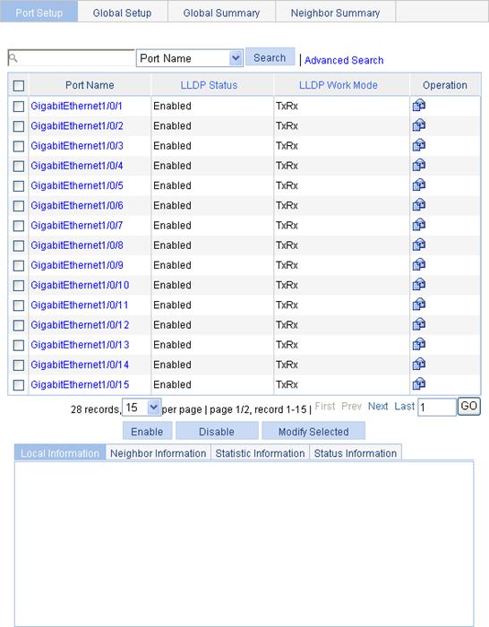
Configuring LLDP settings on ports
The Web interface allows you to set LLDP parameters for a single port, and set LLDP parameters for multiple ports in batch.
Setting LLDP parameters for a single port
1. Select Network > LLDP from the navigation tree.
By default, the Port Setup tab is displayed.
2.
Click the ![]() icon for the port
you are configuring.
icon for the port
you are configuring.
On the page as shown in Figure 70, the LLDP settings of the port are displayed.
Figure 70 Modifying LLDP settings on a port
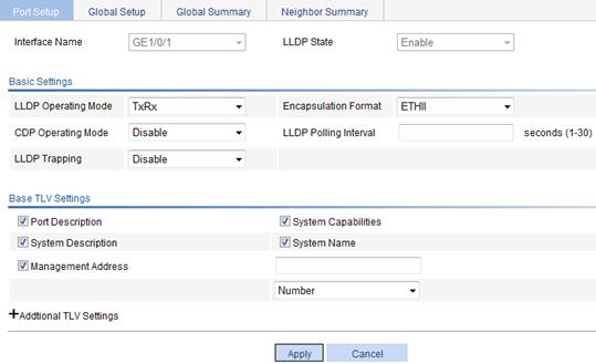
3. Modify the LLDP parameters for the port as described in Table 38.
4. Click Apply.
A progress dialog box appears.
5. Click Close on the progress dialog box when the progress dialog box prompts that the configuration succeeds.
|
Item |
Description |
|
|
Interface Name |
Displays the name of the port or ports you are configuring. |
|
|
DLDP State |
Displays the LLDP enabling status on the port you are configuring. This field is not available when you batch-configure ports. |
|
|
Basic Settings |
LLDP Operating Mode |
Set the LLDP operating mode on the port or ports you are configuring: · TxRx—Sends and receives LLDPDUs. · Tx—Sends but does not receive LLDPDUs. · Rx—Receives but not does not send LLDPDUs. · Disable—Neither sends nor receives LLDPDUs. |
|
Encapsulation Format |
Set the encapsulation for LLDPDUs: · ETHII—Encapsulates outgoing LLDPDUs in Ethernet II frames and processes an incoming LLDPDU only if its encapsulation is Ethernet II. · SNAP—Encapsulates outgoing LLDPDUs in Ethernet II frames and processes an incoming LLDPDU only if its encapsulation is Ethernet II. LLDP-CDP PDUs use only SNAP encapsulation. |
|
|
CDP Operating Mode |
Set the CDP compatibility of LLDP: · Disable—Neither sends nor receives CDPDUs. · TxRx—Sends and receives CDPDUs To enable LLDP to be compatible with CDP on the port, you must enable CDP compatibility on the Global Setup tab and set the CDP operating mode on the port to TxRx. |
|
|
LLDP Polling Interval |
Enable LLDP polling and set the polling interval. If no polling interval is set, LLDP polling is disabled. With the polling mechanism, LLDP periodically detects local configuration changes. If a configuration change is detected, an LLDPDU is sent to inform the LLDP neighbors of the change. |
|
|
LLDP Trapping |
Set the enable status of the LLDP trapping function on the port or ports. LLDP trapping is used to report to the network management station critical events such as new neighbor devices detected and link failures. To avoid excessive traps from being sent when topology is instable, tune the minimum trap transit interval on the Global Setup tab. |
|
|
Base TLV Settings |
Port Description |
Select the box to include the port description TLV in transmitted LLDPDUs. |
|
System Capabilities |
Select the box to include the system capabilities TLV in transmitted LLDPDUs. |
|
|
System Description |
Select the box to include the system description TLV in transmitted LLDPDUs. |
|
|
System Name |
Select the box to include the system name TLV in transmitted LLDPDUs. |
|
|
Management Address |
Select the box to include the management address TLV in transmitted LLDPDUs and, in addition, set the management address and its format (a numeric or character string in the TLV). If no management address is specified, the main IP address of the lowest VLAN carried on the port is used. If no main IP address is assigned to the VLAN, 127.0.0.1 is used. |
|
|
DOT1 TLV Setting |
Port VLAN ID |
Select the box to include the PVID TLV in transmitted LLDPDUs. |
|
Protocol VLAN ID |
Select the box to include port and protocol VLAN ID TLVs in transmitted LLDPDUs and specify the VLAN IDs to be advertised. If no VLAN is specified, the lowest protocol VLAN ID is transmitted. |
|
|
VLAN Name |
Select the box to include VLAN name TLVs in transmitted LLDPDUs, and specify the VLAN IDs to be advertised. If no VLAN is specified, the lowest VLAN carried on the port is advertised. |
|
|
DOT3 TLV Setting |
Link Aggregation |
Select the box to include the link aggregation TLV in transmitted LLDPDUs. |
|
MAC/PHY Configuration/Status |
Select the box to include the MAC/PHY configuration/status TLV in transmitted LLDPDUs. |
|
|
Maximum Frame Size |
Select the box to include the maximum frame size TLV in transmitted LLDPDUs. |
|
|
Power via MDI |
Select the box to include the power via MDI TLV and power stateful control TLV in transmitted LLDPDUs. |
|
|
MED TLV Setting |
LLDP-MED Capabilities |
Select the box to include the LLDP-MED capabilities TLV in transmitted LLDPDUs. |
|
Inventory |
Select the box to include the hardware revision TLV, firmware revision TLV, software revision TLV, serial number TLV, manufacturer name TLV, model name TLV and asset ID TLV in transmitted LLDPDUs. |
|
|
Network Policy |
Select the box to include the network policy TLV in transmitted LLDPDUs. |
|
|
Extended Power-via-MDI Capability |
Select the box to include the extended power-via-MDI TLV in transmitted LLDPDUs. |
|
|
Emergency Number |
Select the box to encode the emergency call number in the location identification TLV in transmitted LLDPDUs and set the emergency call number. |
|
|
Address |
Select Address to encode the civic address information of the network connectivity device in the location identification TLV in transmitted LLDPDUs. In addition, set the device type which can be a switch or LLDP-MED endpoint, country code, and network device address. When you configure the network device address, select the address information type from the list, enter the address information in the field below, and click Add next to the field to add the information to the address information list below. To remove an address information entry, select the entry from the list, and click Delete. The civic address information can include language, province/state, country, city, street, house number, name, postal/zip code, room number, post office box, and, if necessary, additional information. |
|
|
Network Device Address |
||
Configuring LLDP settings for ports in batch
1. Select Network > LLDP from the navigation tree.
By default, the Port Setup tab is displayed.
2. Select one or multiple ports on the port list.
3. Click Modify Selected to enter the page for modifying these ports in batch.
Figure 71 Modifying LLDP settings on ports in batch
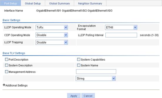
4. Set the LLDP settings for these ports as described in Table 38.
5. Click Apply.
A progress dialog box appears.
6. Click Close on the progress dialog box when the progress dialog box prompts that the configuration succeeds.
Configuring global LLDP setup
1. Select Network > LLDP from the navigation tree.
2. Click the Global Setup tab.
Figure 72 The global setup tab
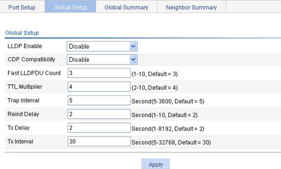
3. Set the global LLDP setup as described in Table 39.
4. Click Apply.
A progress dialog box appears.
5. Click Close on the progress dialog box when the progress dialog box prompts that the configuration succeeds.
|
Item |
Description |
|
LLDP Enable |
Select from the list to enable or disable global LLDP. |
|
CDP Compatibility |
Select from the list to enable or disable CDP compatibility of LLDP. When you configure CDP compatibility, follow these guidelines: · To enable LLDP to be compatible with CDP on a port, you must set the CDP operating mode on the port to TxRx and enable CDP compatibility on the Global Setup tab. · Because the maximum TTL allowed by CDP is 255 seconds, you must make sure the product of the TTL multiplier and the LLDPDU transmit interval is less than 255 seconds for CDP-compatible LLDP to work properly with Cisco IP phones. |
|
Fast LLDPDU Count |
Set the number of LLDPDUs sent each time fast LLDPDU transmission is triggered. |
|
TTL Multiplier |
Set the TTL multiplier. The TTL TLV carried in an LLDPDU determines how long the device information carried in the LLDPDU can be saved on a recipient device. You can configure the TTL of locally sent LLDPDUs to determine how long information about the local device can be saved on a neighbor device by setting the TTL multiplier. The TTL is expressed as TTL multiplier × LLDPDU transit interval. When you configure the TTL multiplier, follow these guidelines: · If the product of the TTL multiplier and the LLDPDU transmit interval is greater than 65535, the TTL carried in transmitted LLDPDUs takes 65535 seconds. · Because the maximum TTL allowed by CDP is 255 seconds, you must make sure the product of the TTL multiplier and the LLDPDU transmit interval is less than 255 seconds for CDP-compatible LLDP to work properly with Cisco IP phones. |
|
Trap Interval |
Set the minimum interval for sending traps. With the LLDP trapping function enabled on a port, traps are sent out of the port to advertise the topology changes detected over the trap interval to neighbors. By tuning this interval, you can prevent excessive traps from being sent when topology is instable. |
|
Reinit Delay |
Set initialization delay for LLDP-enabled ports. Each time the LLDP operating mode of a port changes, its LLDP protocol state machine re-initializes. To prevent LLDP from being initialized too frequently at times of frequent operating mode change, initialization delay is introduced. With this delay mechanism, a port must wait for the specified interval before it can initialize LLDP after the LLDP operating mode changes. |
|
Tx Delay |
Set LLDPDU transmit delay. With LLDP enabled, a port advertises LLDPDUs to its neighbors both periodically and when the local configuration changes. To avoid excessive number of LLDPDUs caused by frequent local configuration changes, an LLDPDU transmit delay is introduced. After sending an LLDPDU, the port must wait for the specified interval before it can send another one. LLDPDU transmit delay must be less than the TTL to make sure the LLDP neighbors can receive LLDPDUs to update information about the device you are configuring before it is aged out. |
|
Tx Interval |
Set the LLDPDU transmit interval. If the product of the TTL multiplier and the LLDPDU transmit interval is greater than 65535, the TTL carried in transmitted LLDPDUs takes 65535 seconds. The likelihood exists that the LLDPDU transmit interval is greater than TTL. You should avoid the situation, because the LLDP neighbors will fail to receive LLDPDUs to update information about the device you are configuring before it is aged out. |
Displaying LLDP information for a port
1. Select Network > LLDP from the navigation tree.
By default, the Port Setup tab is displayed.
2. On the port list, click a port name to display its LLDP information at the lower half of the page.
By default, the Local Information tab is displayed. Table 40 describes the fields.
Figure 73 The local information tab
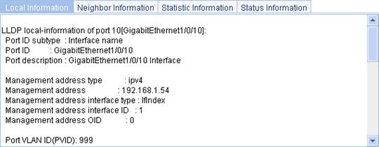
|
Field |
Description |
|
Port ID subtype |
Port ID type: · Interface alias. · Port component. · MAC address. · Network address. · Interface name. · Agent circuit ID. · Locally assigned, or the local configuration. |
|
Port power classification |
Port power classification of the PD: · Unknown. · Class0. · Class1. · Class2. · Class3. · Class4. |
|
Media policy type |
Media policy type: · Unknown. · Voice. · Voice signaling. · Guest voice. · Guest voice signaling. · Soft phone voice. · Videoconferencing. · Streaming video. · Video signaling. |
|
PoE PSE power source |
Type of PSE power source advertised by the local device: · Primary. · Backup. |
|
Port PSE priority |
PSE priority of the port: · Unknown—Unknown PSE priority. · Critical—Priority level 1. · High—Priority level 2. · Low—Priority level 3. |
3. Click the Neighbor Information tab to display the LLDP neighbor information.
Table 41 describes the fields.
Figure 74 The Neighbor Information tab
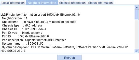
|
Field |
Description |
|
Chassis type |
Chassis ID type: · Chassis component. · Interface alias. · Port component. · MAC address. · Network address. · Interface name. · Locally assigned, or the local configuration. |
|
Chassis ID |
Chassis ID depending on the chassis type, which can be a MAC address of the device. |
|
Port ID type |
Port ID type: · Interface alias. · Port component. · MAC address. · Network address. · Interface name. · Agent circuit ID. · Locally assigned, or the local configuration. |
|
Port ID |
Port ID value. |
|
System capabilities supported |
Primary network function of the system: · Repeater. · Bridge. · Router. |
|
System capabilities enabled |
Network function enabled on the system: · Repeater. · Bridge. · Router. |
|
Auto-negotiation supported |
Support of the neighbor for auto negotiation. |
|
Auto-negotiation enabled |
Enabling status of auto negotiation on the neighbor. |
|
OperMau |
Current speed and duplex mode of the neighbor. |
|
Link aggregation supported |
Support of the neighbor for link aggregation. |
|
Link aggregation enabled |
Enabling status of link aggregation on the neighbor. |
|
Aggregation port ID |
Link aggregation group ID. It is 0 if the neighbor port is not assigned to any link aggregation group. |
|
Maximum frame Size |
Maximum frame size supported on the neighbor port. |
|
Device class |
MED device type: · Connectivity device—An intermediate device that provide network connectivity. · Class I—A generic endpoint device. All endpoints that require the discovery service of LLDP belong to this category. · Class II—A media endpoint device. The class II endpoint devices support the media stream capabilities and the capabilities of generic endpoint devices. · Class III—A communication endpoint device. The class III endpoint devices directly support end users of the IP communication system. Providing all capabilities of generic and media endpoint devices, Class III endpoint devices are used directly by end users. |
|
Media policy type |
Media policy type: · Unknown. · Voice. · Voice signaling. · Guest voice. · Guest voice signaling. · Soft phone voice. · Videoconferencing. · Streaming video. · Video signaling. |
|
Unknown Policy |
Indicates whether the media policy type is unknown. |
|
VLAN tagged |
Indicates whether packets of the media VLAN are tagged. |
|
Media policy VlanID |
ID of the media VLAN. |
|
Media policy L2 priority |
Layer 2 priority. |
|
Media policy Dscp |
DSCP precedence. |
|
HardwareRev |
Hardware version of the neighbor. |
|
FirmwareRev |
Firmware version of the neighbor. |
|
SoftwareRev |
Software version of the neighbor. |
|
SerialNum |
Serial number advertised by the neighbor. |
|
Manufacturer name |
Manufacturer name advertised by the neighbor. |
|
Model name |
Model name advertised by the neighbor. |
|
Asset tracking identifier |
Asset ID advertised by the neighbor. This ID is used for the purpose of inventory management and asset tracking. |
|
PoE PSE power source |
Type of PSE power source advertised by the neighbor: · Primary. · Backup. |
|
Port PSE priority |
PSE priority of the port: · Unknown—Unknown PSE priority. · Critical—Priority level 1. · High—Priority level 2. · Low—Priority level 3. |
4. Click the Statistics Information tab to display the LLDP statistics.
Figure 75 The statistic information tab
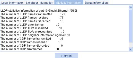
5. Click the Status Information tab to display the LLDP status information.
Figure 76 The status information tab
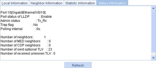
Displaying global LLDP information
1. Select Network > LLDP from the navigation tree.
2. Click the Global Summary tab to display global local LLDP information and statistics.
Table 42 describes the fields.
Figure 77 The global summary tab
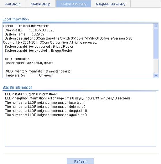
|
Field |
Description |
|
Chassis ID |
Local chassis ID depending on the chassis type defined. |
|
System capabilities supported |
Primary network function advertised by the local device: · Repeater. · Bridge. · Router. |
|
System capabilities enabled |
Enabled network function advertised by the local device: · Repeater. · Bridge. · Router. |
|
Device class |
Device class advertised by the local device: · Connectivity device—An intermediate device that provide network connectivity. · Class I—A generic endpoint device. All endpoints that require the discovery service of LLDP belong to this category. · Class II—A media endpoint device. The class II endpoint devices support the media stream capabilities and the capabilities of generic endpoint devices. · Class III—A communication endpoint device. The class III endpoint devices directly support end users of the IP communication system. Providing all capabilities of generic and media endpoint devices, Class III endpoint devices are used directly by end users. |
Displaying LLDP information received from LLDP neighbors
1. Select Network > LLDP from the navigation tree.
2. Click the Neighbor Summary tab to display the global LLDP neighbor information, as shown in Figure 78.
Figure 78 The neighbor summary tab
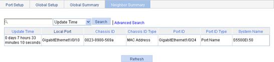
LLDP configuration examples
LLDP basic settings configuration example
Network requirements
As shown in Figure 79, configure LLDP on Switch A and Switch B so that the NMS can determine the status of the link between Switch A and MED and the link between Switch A and Switch B.
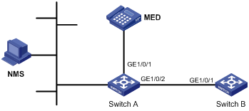
Configuring Switch A
1. (Optional.) Enable LLDP on GigabitEthernet 1/0/1 and GigabitEthernet 1/0/2. (By default, LLDP is enabled on Ethernet ports.)
2. Set the LLDP operating mode to Rx on GigabitEthernet 1/0/1 and GigabitEthernet 1/0/2:
a. Select Network > LLDP from the navigation tree.
By default, the Port Setup tab is displayed, as shown in Figure 80.
b. Select port GigabitEthernet1/0/1 and GigabitEthernet1/0/2.
c. Click Modify Selected.
The page shown in Figure 81 appears.
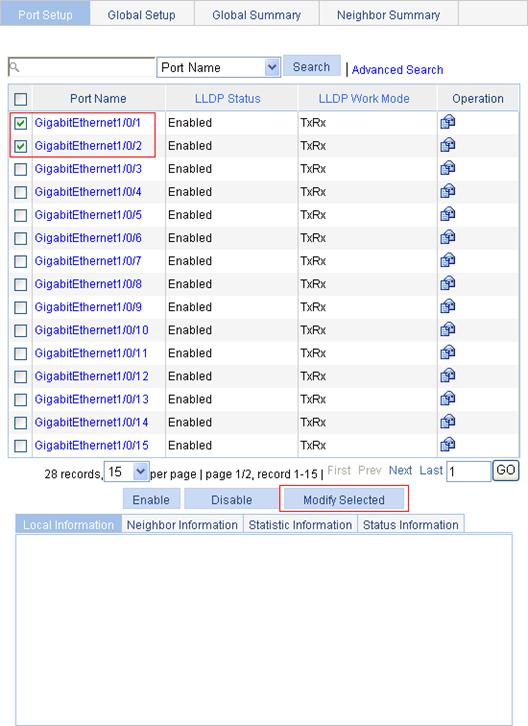
d. Select Rx from the LLDP Operating Mode list.
3. Click Apply.
A progress dialog box appears.
4. Click Close on the progress dialog box when the progress dialog box prompts that the configuration succeeds.
Figure 81 Setting LLDP on multiple ports
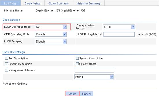
5. Enable global LLDP:
a. Click the Global Setup tab, as shown in Figure 82.
b. Select Enable from the LLDP Enable list.
6. Click Apply.
A progress dialog box appears.
7. Click Close on the progress dialog box when the progress dialog box prompts that the configuration succeeds.
Figure 82 The global setup tab
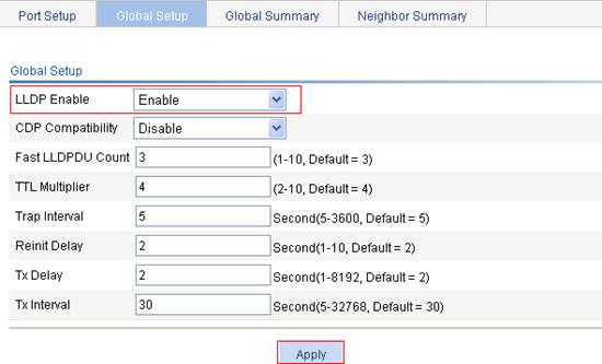
Configuring Switch B
1. (Optional.) Enable LLDP on port GigabitEthernet 1/0/1. (By default, LLDP is enabled on Ethernet ports.)
2. Set the LLDP operating mode to Tx on GigabitEthernet 1/0/1:
a. Select Network > LLDP from the navigation tree.
By default, the Port Setup tab is displayed.
b. Click the ![]() icon for port GigabitEthernet1/0/1.
icon for port GigabitEthernet1/0/1.
c. Select Tx from the LLDP Operating Mode list.
3. Click Apply.
A progress dialog box appears.
4. Click Close on the progress dialog box when the progress dialog box prompts that the configuration succeeds.
Figure 83 Setting the LLDP operating mode to Tx
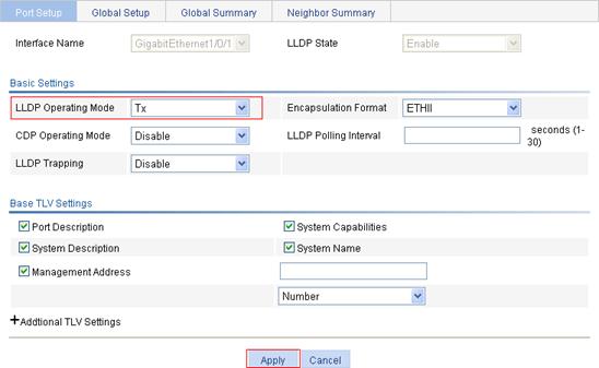
5. Enable global LLDP:
a. Click the Global Setup tab.
b. Select Enable from the LLDP Enable list.
6. Click Apply.
A progress dialog box appears.
7. Click Close on the progress dialog box when the progress dialog box prompts that the configuration succeeds.
Verifying the configuration
1. Display the status information of port GigabitEthernet1/0/1 on Switch A:
a. Select Network > LLDP from the navigation tree.
By default, the Port Setup tab is displayed.
b. Click the GigabitEthernet1/0/1 port name in the port list.
c. Click the Status Information tab at the lower half of the page.
The output shows that port GigabitEthernet 1/0/1 is connected to an MED neighbor device.
Figure 84 The status information tab (1)

2. Display the status information of port GigabitEthernet1/0/2 on Switch A:
a. Click the GigabitEthernet1/0/2 port name in the port list.
b. Click the Status Information tab at the lower half of the page.
The output shows that port GigabitEthernet 1/0/2 is connected to a non-MED neighbor device (Switch B), as shown in Figure 85.
Figure 85 The status information tab (2)
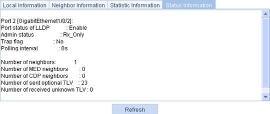
3. Tear down the link between Switch A and Switch B.
4. Click Refresh to display the status information of port GigabitEthernet1/0/2 on Switch A.
The updated status information of port GigabitEthernet 1/0/2 shows that no neighbor device is connected to the port, as shown in Figure 86.
Figure 86 The status information tab displaying the updated port status information

CDP-compatible LLDP configuration example
Network requirements
As shown in Figure 87, on Switch A, configure VLAN 2 as a voice VLAN and configure CDP-compatible LLDP to enable the Cisco IP phones to automatically configure the voice VLAN, confining their voice traffic within the voice VLAN to be separate from other types of traffic.

Configuring Switch A
1. Create VLAN 2:
a. Select Network > VLAN from the navigation tree.
b. Click Create to enter the page for creating VLANs.
c. Enter 2 in the VLAN IDs field.
d. Click Create.
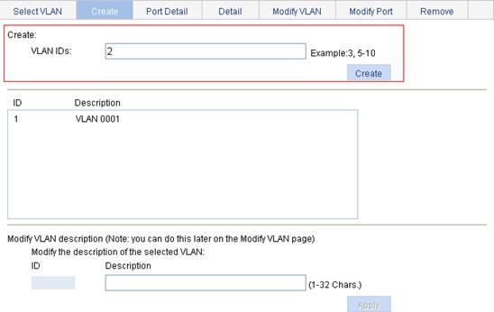
2. Configure GigabitEthernet 1/0/1 and GigabitEthernet 1/0/2 as trunk ports:
a. Select Device > Port Management from the navigation tree.
b. Click the Setup tab to enter the page for configuring ports.
c. Select Trunk from the Link Type list.
d. Select port GigabitEthernet 1/0/1 and GigabitEthernet 1/0/2 from the chassis front panel.
e. Click Apply.
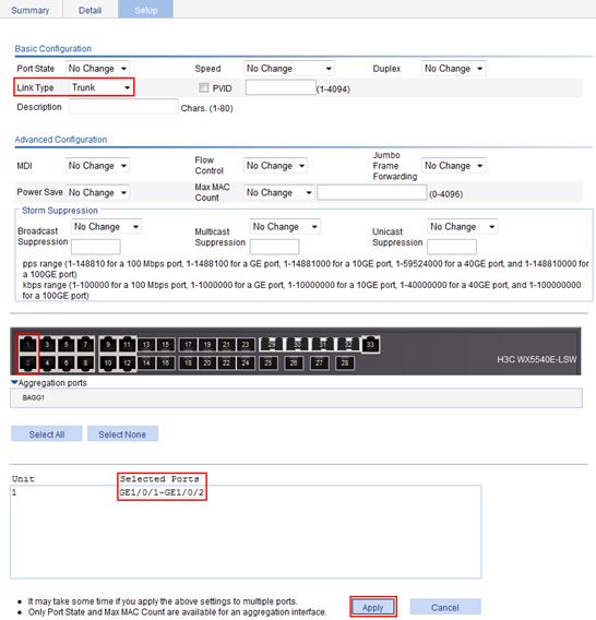
3. Configure the voice VLAN function on the two ports:
a. Select Network > Voice VLAN from the navigation tree.
b. Click the Port Setup tab to enter the page for configuring the voice VLAN function on ports.
c. Select Auto from the Voice VLAN port mode list, select Enable from the Voice VLAN port state list, enter the voice VLAN ID 2, and select port GigabitEthernet 1/0/1 and GigabitEthernet 1/0/2 from the chassis front panel.
d. Click Apply.
Figure 90 Configuring the voice VLAN function on ports
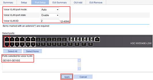
4. Enable LLDP on ports GigabitEthernet 1/0/1 and GigabitEthernet 1/0/2.
Skip this step if LLDP is enabled (the default).
5. Set both the LLDP operating mode and the CDP operating mode to TxRx on ports GigabitEthernet 1/0/1 and GigabitEthernet 1/0/2:
a. Select Network > LLDP from the navigation tree.
By default, the Port Setup tab is displayed.
Figure 91 The port setup tab
b. Select port GigabitEthernet1/0/1 and GigabitEthernet1/0/2.
c. Click Modify Selected.
The page shown in Figure 92 is displayed.
d. Select TxRx from the LLDP Operating Mode list, and select TxRx from the CDP Operating Mode list.
e. Click Apply.
A progress dialog box appears.
f. Click Close on the progress dialog box when the progress dialog box prompts that the configuration succeeds.
Figure 92 Modifying LLDP settings on ports
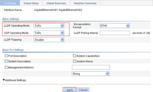
6. Enable global LLDP and CDP compatibility of LLDP:
a. Click the Global Setup tab.
b. Select Enable from the LLDP Enable list.
c. Select Enable from the CDP Compatibility list.
d. Click Apply.
A progress dialog box appears.
e. Click Close on the progress dialog box when the progress dialog box prompts that the configuration succeeds.
Figure 93 The global setup tab
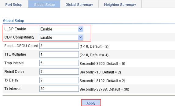
Verifying the configuration
Display information about LLDP neighbors on Switch A after completing the configuration. The output shows Switch A has discovered the Cisco IP phones attached to ports GigabitEthernet1/0/1 and GigabitEthernet1/0/2 and obtained their device information.
Overview
Service management allows you to manage the following types of services: FTP, Telnet, SSH, SFTP, HTTP and HTTPS.
You can enable or disable the services, modify HTTP and HTTPS port numbers, and associate the FTP, HTTP, or HTTPS service with an ACL to block illegal users.
FTP service
FTP is an application layer protocol for sharing files between server and client over a TCP/IP network.
Telnet service
Telnet is an application layer protocol that provides remote login and virtual terminal functions.
SSH service
Secure Shell (SSH) offers an approach to securely logging in to a remote device. By encryption and strong authentication, it protects devices against attacks such as IP spoofing and plain text password interception.
SFTP service
The secure file transfer protocol (SFTP) is a new feature in SSH2.0. SFTP uses the SSH connection to provide secure data transfer. The device can serve as the SFTP server, allowing a remote user to log in to the SFTP server for secure file management and transfer. The device can also serve as an SFTP client, enabling a user to login from the device to a remote device for secure file transfer.
HTTP service
HTTP is used for transferring webpage information across the Internet. It is an application-layer protocol in the TCP/IP protocol suite.
You can log in to the device by using the HTTP protocol with HTTP service enabled, accessing and controlling the device with Web-based network management.
HTTPS service
The Hypertext Transfer Protocol Secure (HTTPS) refers to the HTTP protocol that supports the Security Socket Layer (SSL) protocol.
The SSL protocol of HTTPS enhances the security of the device in the following ways:
· Uses the SSL protocol to ensure the legal clients to access the device securely and prohibit the illegal clients.
· Encrypts the data exchanged between the HTTPS client and the device to ensure the data security and integrity.
· Defines certificate attribute-based access control policy for the device to control user access.
Managing services
1. Select Network > Service from the navigation tree to enter the service management configuration page, as shown in Figure 94.
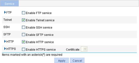
2. Enable or disable various services on the page. Table 43 describes the detailed configuration items.
3. Click Apply.
|
Item |
Description |
|
|
FTP |
Enable FTP service. |
Enable or disable the FTP service. The FTP service is disabled by default. |
|
ACL. |
Associate the FTP service with an ACL. Only the clients that pass the ACL filtering are permitted to use the FTP service. You can view this configuration item by clicking the expanding button in front of FTP. |
|
|
Telnet |
Enable Telnet service. |
Enable or disable the Telnet service. The Telnet service is disabled by default. |
|
SSH |
Enable SSH service. |
Enable or disable the SSH service. The SSH service is disabled by default. |
|
SFTP |
Enable SFTP service. |
Enable or disable the SFTP service. The SFTP service is disabled by default.
When you enable the SFTP service, the SSH service must be enabled. |
|
HTTP |
Enable HTTP service. |
Enable or disable the HTTP service. The HTTP service is enabled by default. |
|
Port Number. |
Set the port number for HTTP service. You can view this configuration item by clicking the expanding button in front of HTTP.
When you modify a port, make sure the port is not used by any other service. |
|
|
ACL. |
Associate the HTTP service with an ACL. Only the clients that pass the ACL filtering are permitted to use the HTTP service. You can view this configuration item by clicking the expanding button in front of HTTP. |
|
|
HTTPS |
Enable HTTPS service. |
Enable or disable the HTTPS service. The HTTPS service is disabled by default. |
|
Certificate. |
Select a local certificate for the HTTPS service from the Certificate dropdown list. You can configure the certificates available in the dropdown list in Authentication > Certificate Management. For more information, see "Managing certificates."
If no certificate is specified, the HTTPS service generates its own certificate. |
|
|
Port Number. |
Set the port number for HTTPS service. You can view this configuration item by clicking the expanding button in front of HTTPS.
When you modify a port, make sure the port is not used by any other service. |
|
|
ACL. |
Associate the HTTPS service with an ACL. Only the clients that pass the ACL filtering are permitted to use the HTTPS service. You can view this configuration item by clicking the expanding button in front of HTTPS. |
|
This chapter describes how to use the ping and traceroute facilities.
Ping
You can ping the IP address or the host name of a device.
If the host name cannot be resolved, a prompt appears. If the source device does not receive an ICMP echo reply within the timeout time, it displays a prompt and ping statistics. If the source device receives ICMP echo replies within the timeout time, it displays the number of bytes for each echo reply, the message sequence number, Time to Live (TTL), the response time, and ping statistics. Ping statistics include number of packets sent, number of echo reply messages received, percentage of messages not received, and the minimum, average, and maximum response time.
A ping operation involves the following steps:
1. The source device sends ICMP echo requests to the destination device.
2. The destination device responds by sending ICMP echo replies to the source device after receiving the ICMP echo requests.
3. The source device displays related statistics after receiving the replies.
Traceroute
By using the traceroute facility, you can display the Layer 3 devices involved in delivering a packet from source to destination. This function is useful for identification of failed nodes.
You can traceroute the IP address or the host name of the destination device. If the target host name cannot be resolved, a prompt appears.
A traceroute operation involves the following steps:
1. The source device sends a packet with a Time to Live (TTL) value of 1 to the destination device.
2. The first hop device responds with an ICMP TTL-expired message to the source. In this way, the source device can get the address of the first Layer 3 device.
3. The source device sends a packet with a TTL value of 2 to the destination device.
4. The second hop responds with an ICMP TTL-expired message.
5. The above process continues until the ultimate destination device is reached. The destination device responds with an ICMP port-unreachable message because the packet from the source has an unreachable port number. In this way, the source device can get the addresses of all Layer 3 devices on the path.
Ping operation
To perform a ping operation:
1. Select Network > Diagnostic Tools from the navigation tree.
The ping configuration page appears.
Figure 95 Ping configuration page
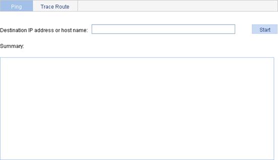
2. Enter the IP address or the host name of the destination device in the Destination IP address or host name field.
3. Click Start.
4. View the result in the Summary area.
Figure 96 Ping operation result
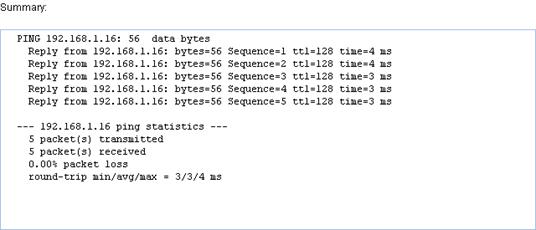
Traceroute operation
Before performing a traceroute operation, execute the ip ttl-expires enable command on intermediate devices to enable the sending of ICMP timeout packets and execute the ip unreachables enable command on the destination device to enable the sending of ICMP destination unreachable packets.
To perform a traceroute operation:
1. Select Network > Diagnostic Tools from the navigation tree.
2. Click the Trace Route tab.
The traceroute configuration page appears.
Figure 97 Traceroute configuration page
3. Enter the IP address or host name of the destination device in the Trace Route field.
4. Click Start.
5. View the output in the Summary area.
Figure 98 Traceroute operation result