- Table of Contents
- Related Documents
-
| Title | Size | Download |
|---|---|---|
| 07-Track Configuration | 354.58 KB |
Contents
Collaboration application example
Associating the track module with a detection module
Associating track with interface management
Associating the track module with an application module
Associating track with static routing
Associating track with traffic redirection
Displaying and maintaining track entries
VRRP-track-NQA collaboration configuration example (the master monitors the uplinks)
Configuring BFD for a vrrp backup to monitor the master
Configuring BFD for the VRRP master to monitor the uplink
Static routing-track-NQA collaboration configuration example
Static routing-track-BFD collaboration configuration example
Track overview
Introduction to collaboration
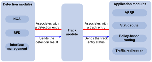
The track module works between application and detection modules, as Figure 1 shows. It hides the differences among detection modules from application modules.
Collaboration is enabled after you associate the track module with a detection module and an application module respectively. The detection module monitors specific objects such as interface status, link status, network reachability, and network performance, and informs the track module of detection results. The track module sends the detection results to the associated application module, and the application module takes actions when the tracked object changes its state.
Figure 1 Collaboration through the track module
Collaboration fundamentals
The track module collaborates with detection modules and application modules:
· Collaboration between the track module and a detection module
· Collaboration between the track module and an application module
Collaboration between the track module and a detection module
After being associated with a track entry, the detection module sends the detection result of the tracked object to the track module, which then changes the status of the track entry:
· If the tracked object functions normally, for example, the target interface is up or the target network is reachable, the state of the track entry is Positive.
· If the tracked object functions abnormally, for example, the target interface is down or the target network is unreachable, the state of the track entry is Negative.
· If the detection result is not valid, for example, the NQA test group that is associated with the track entry does not exist, the state of the track entry is Invalid.
The detection modules that can be associated with the track module include:
· NQA
· BFD
· Interface management module
Collaboration between the track module and an application module
After being associated with an application module, when the status of the track entry changes, the track module notifies the application module, which then takes proper actions.
The application modules that can be associated with the track module include:
· Virtual Router Redundancy Protocol (VRRP)
· Static routing
· Policy-based routing
· Traffic redirection
Collaboration application example
The following describes how NQA, track, and static routing collaborate.
Configure a static route with next hop 192.168.0.88 on the device. If the next hop is reachable, the static route is valid. If the next hop becomes unreachable, the static route should become invalid. For this purpose, configure collaboration between the NQA, track, and static routing modules:
1. Create an NQA test group to monitor the reachability of IP address 192.168.0.88.
2. Create a track entry and associate it with the NQA test group. When the next hop 192.168.0.88 is reachable, the track entry is in Positive state. When the next hop becomes unreachable, the track entry is in Negative state.
3. Associate the track entry with the static route. When the track entry turns to the Positive state, the static route is valid. When the associated track entry turns to the Negative state, the static route is invalid.
Track configuration task list
To implement the collaboration function, establish associations between the track module and the detection modules, and between the track module and the application modules.
Complete these tasks to configure the track module:
|
Task |
Remarks |
|
|
Required Use any of the approaches. |
||
|
Required Use any of the approaches. |
||
Associating the track module with a detection module
Associating track with NQA
NQA supports multiple test types to analyze network performance, services, service quality. For example, an NQA test group can periodically detect whether a destination is reachable, or whether the TCP connection to a TCP server can be set up. After being associated with a track entry, an NQA test group tells the track module that the tracked object malfunctions when the consecutive failures reach the specified threshold. Then the track module sets the track entry to the Negative state. If the specified threshold is not reached, the NQA module tells the track module that the tracked object functions normally. The track module then sets the track entry to the Positive state. For more information about NQA, see Network Management and Monitoring Configuration Guide.
To associate track with NQA:
|
Step |
Command |
Remarks |
|
1. Enter system view. |
system-view |
N/A |
|
2. Create a track entry, associate it with an NQA reaction entry, and specify the delay time for the track module to notify the associated application module when the track entry status changes. |
track track-entry-number nqa entry admin-name operation-tag reaction item-number [ delay { negative negative-time | positive positive-time } * ] |
No track entry is created by default. |
|
|
NOTE: If the specified NQA test group or the reaction entry in the track entry does not exist, the status of the track entry is Invalid. |
Associating track with BFD
BFD supports the control packet mode and echo mode. Only echo-mode BFD can be associated with a track entry.
After being associated with a track entry, the BFD informs the track entry of link failures, and then the track module sets the track entry to the Negative state. If the BFD detects the link is normal, the track module sets the track entry to the Positive state. For more information about BFD, see the chapter “Configuring BFD.”
Configuration prerequisites
Before you associate track with BFD, configure the source address of the BFD echo packets.
Configuration procedure
To associate track with BFD:
|
Step |
Command |
Remarks |
|
1. Enter system view. |
system-view |
N/A |
|
2. Create a track entry, associate it with the BFD session, and specify the delay time for the track module to notify the associated application module when the track entry status changes. |
track track-entry-number bfd echo interface interface-type interface-number remote ip remote-ip local ip local-ip [ delay { negative negative-time | positive positive-time } * ] |
No track entry is created by default. |
|
|
NOTE: When associating track with BFD, do not configure the virtual IP address of a VRRP group as the local or remote address of a BFD session. |
Associating track with interface management
The interface management module monitors the physical status or network-layer protocol status of the interface. After being associated with a track entry, when the physical or network-layer protocol status of the interface changes to up, the interface management module informs the track module of the change and the track module sets the track entry to Positive. When the physical or network-layer protocol status of the interface changes to down, the interface management module informs the track module of the change and the track module sets the track entry to Negative.
To associate track with interface management:
|
Step |
Command |
Remarks |
|
1. Enter system view. |
system-view |
N/A |
|
2. Associate track with interface management. |
·
Create a track entry, associate it with the interface
management module to monitor the physical status of an interface, and specify
the delay time for the track module to notify the associated application
module when the track entry status changes: ·
Create a track entry, associate it with the interface
management module to monitor the Layer 3 protocol status of an interface, and
specify the delay time for the track module to notify the associated
application module when the track entry status changes: |
Use either approach. No track entry is created by default. |
Associating the track module with an application module
Associating track with VRRP
VRRP is an error-tolerant protocol. It adds a group of routers that can act as network gateways to a VRRP group, which forms a virtual router. Routers in the VRRP group elect the master acting as the gateway according to their priorities. A router with a higher priority is more likely to become the master. The other routers function as the backups. When the master fails, to guarantee that the hosts in the network segment can uninterruptedly communicate with external networks, the backups in the VRRP group elect a new gateway to undertake the responsibility of the failed master.
When VRRP works in standard protocol mode or load balancing mode, associate the track with the VRRP group to implement the following actions:
· Change the priority of a router according to the status of the uplink. If a fault occurs on the uplink of the router, the VRRP group cannot be aware of the uplink failure. If the router is the master, hosts in the LAN cannot access the external network. This problem can be solved by establishing a track-VRRP group association. Use the detection modules to monitor the status of the uplink of the router and establish the collaborations between the detection modules, track module and VRRP. When the uplink fails, the detection modules notify the track module to change the status of the monitored track entry to Negative, and the priority of the master then decreases by a specific value, allowing a higher priority router in the VRRP group to become the master to maintain proper communication between the hosts in the LAN and the external network.
· Monitor the master on a backup. If a fault occurs on the master, the backup working in the switchover mode will switch to the master immediately to maintain normal communication.
When VRRP works in the load balancing mode, through the association between the track module and VRRP Virtual Forwarder (VF), you can change the priority of a VF according to the status of the uplink. When the uplink of the active VF (AVF) fails, the status of the track entry changes to Negative and the weight of the VF decreases by a specific value so that the VF with a higher priority becomes the AVF and forwards packets.
To associate track with VRRP group:
|
Step |
Command |
Remarks |
|
1. Enter system view. |
system-view |
N/A |
|
2. Enter interface view. |
interface interface-type interface-number |
N/A |
|
3. Create a VRRP group and configure its virtual IP address. |
vrrp vrid virtual-router-id virtual-ip virtual-address |
No VRRP group is created by default. |
|
4. Associate a track entry with a VRRP group. |
vrrp [ ipv6 ] vrid virtual-router-id track track-entry-number [ reduced priority-reduced | switchover ] |
No track entry is specified for a VRRP group by default. This command is supported when VRRP works in both the standard protocol mode and load balancing mode. |
To associate track with VRRP VF:
|
Step |
Command |
Remarks |
|
1. Enter system view. |
system-view |
N/A |
|
2. Enter interface view. |
interface interface-type interface-number |
N/A |
|
3. Create a VRRP group and configure its virtual IP address. |
vrrp vrid virtual-router-id virtual-ip virtual-address |
No VRRP group is created by default. |
|
4. Associate a track entry with the VRRP VF. |
vrrp [ ipv6 ] vrid virtual-router-id weight track track-entry-number [ reduced weight-reduced ] |
By default, no track entry is specified for a VF. This command is supported when VRRP works in both standard protocol mode and load balancing mode. However, this function takes effect only when VRRP works in load balancing mode. |
|
|
NOTE: · VRRP tracking is not valid on an IP address owner. An IP address owner refers to a router when the IP address of the virtual router is the IP address of an interface on the router in the VRRP group. · When the status of the track entry changes from Negative to Positive or Invalid, the associated router or VF restores its priority automatically. · You can associate a track entry with a VRRP group or VF before or after you create the track entry. However, the association takes effect only after you create the track entry with the track command. · For more information about VRRP, see the chapter “Configuring VRRP.” |
Associating track with static routing
A static route is a manually configured route. With a static route configured, packets to the specified destination are forwarded through the path specified by the administrator.
The disadvantage of using static routes is that they cannot adapt to network topology changes. If a fault or a topological change occurs in the network, the routes will be unreachable and the network breaks.
To prevent this problem, configure another route to back up the static route. When the static route is reachable, packets are forwarded through the static route; when the static route is unreachable, packets are forwarded through the backup route, avoiding network break and enhancing network reliability.
To check the reachability of a static route in real time, establish association between the track and the static route.
If you specify the next hop but not the egress interface when configuring a static route, you can establish collaborations among the static route, the track module, and detection modules to check the reachability of the static route according to the status of the track entry.
· The Positive state of the track entry shows that the next hop of the static route is reachable, and the configured static route is valid.
· The Negative state of the track entry shows that the next hop of the static route is not reachable, and the configured static route is invalid.
· The Invalid state of the track entry shows that the reachability of the next hop of the static route is unknown, and the static route is valid.
To associate track with static routing:
|
Step |
Command |
Remarks |
|
1. Enter system view. |
system-view |
N/A |
|
2. Associate the static route with a track entry to check the reachability of the next hop. |
·
Approach 1: ·
Approach 2: |
Use either approach. Not configured by default. |
|
|
NOTE: · If you associate a track entry with a nonexistent static route, the static route is automatically created. · You can associate a track entry with a static route before or after you create the track entry. However, the association takes effect only after you create the track entry with the track command. · If the track module detects the next hop reachability of the static route in a private network through NQA, the VPN instance name of the next hop of the static route must be consistent with that configured for the NQA test group. Otherwise, the reachability detection cannot function properly. · If a static route needs route recursion, the associated track entry must monitor the next hop of the recursive route instead of that of the static route; otherwise, a valid route may be considered invalid. · For more information about static route configuration, see Layer 3—IP Routing Configuration Guide. |
Associating track with PBR
Policy-based routing (PBR) is a routing mechanism based on user-defined policies. Different from the traditional destination-based routing mechanism, PBR enables you to use a policy (based on the source address, packet length, and other criteria) to route packets. You can specify the VPN instance, packet priority, outgoing interface, next hop, default outgoing interface, default next hop, and other parameters to guide the forwarding of packets that match specific ACLs or have specific lengths.
PBR cannot detect the availability of any action taken on packets. When an action is not available, packets processed by the action may be discarded. For example, configure PBR to forward packets that match certain criteria through a specific interface. When the specified interface fails, PBR cannot sense the failure, and continues to forward matching packets out of the interface.
This problem can be solved by associating track with PBR, which improves the flexibility of PBR application, and enables PBR to sense topology changes.
After you associate a track entry with an apply clause, the detection module associated with the track entry sends the detection result of the availability of the object (an interface or an IP address) specified in the apply clause.
· The Positive state of the track entry shows that the object is available, and the apply clause is valid.
· The Negative state of the track entry shows that the object is not available, and the apply clause is invalid.
· The Invalid state of the track entry shows that the apply clause is valid.
The objects that can be associated with a track entry include:
· Outgoing interface
· Next hop
· Default outgoing interface
· Default next hop
Configuration prerequisites
Before you associate track with PBR, create a policy or a policy node and configure the match criteria as well.
Configuration procedure
To associate track with PBR:
|
Step |
Command |
Remarks |
|
1. Enter system view. |
system-view |
N/A |
|
2. Create a policy or policy node and enter PBR policy node view. |
policy-based-route policy-name [ deny | permit ] node node-number |
N/A |
|
3. Define a match criterion. |
· Define a packet length match criterion: · Define an ACL match criterion: |
Optional. By default, no packets are filtered. |
|
4. Associate track with PBR. |
· Set the outgoing interface, and associate it with a track entry: · Set the next hop and associate it with a track entry: · Set the default outgoing interface, and associate it with a track
entry: · Set the default next hop, and associate it with a track entry: |
Configure at least one of the commands. |
|
|
NOTE: · You can associate a track entry with PBR before or after you create the track entry. However, the association takes effect only after you create the track entry with the track command. · For more information about PBR, see Layer 3—IP Routing Configuration Guide. |
Associating track with traffic redirection
Traffic redirection is the action of redirecting the packets matching specific criteria to a certain location for processing, such as to an interface, a CPU, or a next hop. When the next hop is not reachable, packets redirected to it are lost. To check the reachability of the next hop in real time, establish association between track and traffic redirection.
· The Positive state of the track entry shows that the next hop is reachable, and traffic redirection redirects packets to the next hop.
· The Negative state of the track entry shows that the next hop is not reachable, and traffic redirection does not redirect packets. The packets are forwarded based on the routing table lookup result.
· The Invalid state of the track entry shows that reachability of the next hop is unknown, and traffic redirection redirects packets to the next hop of the unknown state.
To associate track with traffic redirection:
|
Step |
Command |
Remarks |
|
1. Enter system view. |
system-view |
N/A |
|
2. Create a behavior and enter behavior view. |
traffic behavior behavior-name |
N/A |
|
3. Associate track with traffic redirection. |
·
Associate the traffic redirect action
with a track entry: ·
Associate the default traffic redirect
action with a track entry: |
Use either approach. Not configured by default. |
|
|
NOTE: For more information about traffic redirection, see ACL and QoS Configuration Guide. |
Displaying and maintaining track entries
|
Task |
Command |
Remarks |
|
Display information about the specified or all track entries. |
display track { track-entry-number | all } [ | { begin | exclude | include } regular-expression ] |
Available in any view |
Track configuration examples
VRRP-track-NQA collaboration configuration example (the master monitors the uplinks)
Network requirements
· As shown in Figure 2, Host A needs to access Host B on the Internet. The default gateway of Host A is 10.1.1.10/24.
· Router A and Router B belong to VRRP group 1, whose virtual IP address is 10.1.1.10.
· When Router A works normally, packets from Host A to Host B are forwarded through Router A. When NQA detects that a fault is on the uplink of Router A, packets from Host A to Host B are forwarded through Router B.

Configuration procedure
1. Configure the IP address of each interface as shown in Figure 2.
2. Configure an NQA test group on Router A:
<RouterA> system-view
# Create an NQA test group with the administrator name admin and the operation tag test.
[RouterA] nqa entry admin test
# Configure the test type as ICMP echo test.
[RouterA-nqa-admin-test] type icmp-echo
# Configure the destination address as 10.1.2.2.
[RouterA-nqa-admin-test-icmp-echo] destination ip 10.1.2.2
# Configure the interval between two consecutive tests as 100 milliseconds.
[RouterA-nqa-admin-test-icmp-echo] frequency 100
# Create reaction entry 1, specifying that five consecutive probe failures trigger the track module.
[RouterA-nqa-admin-test-icmp-echo] reaction 1 checked-element probe-fail threshold-type consecutive 5 action-type trigger-only
[RouterA-nqa-admin-test-icmp-echo] quit
# Start the NQA test.
[RouterA] nqa schedule admin test start-time now lifetime forever
3. Configure a track entry on Router A:
# Configure track entry 1, and associate it with reaction entry 1 of the NQA test group (with the administrator admin, and the operation tag test).
[RouterA] track 1 nqa entry admin test reaction 1
4. Configure VRRP on Router A:
# Create VRRP group 1, and configure the virtual IP address 10.1.1.10 for the group.
[RouterA] interface GigabitEthernet 3/1/10
[RouterA-GigabitEthernet3/1/10] vrrp vrid 1 virtual-ip 10.1.1.10
# Set the priority of Router A in VRRP group 1 to 110.
[RouterA-GigabitEthernet3/1/10] vrrp vrid 1 priority 110
# Set the authentication mode of VRRP group 1 to simple, and the authentication key to hello.
[RouterA-GigabitEthernet3/1/10] vrrp vrid 1 authentication-mode simple hello
# Configure the master to send VRRP packets at an interval of five seconds.
[RouterA-GigabitEthernet3/1/10] vrrp vrid 1 timer advertise 5
# Configure Router A to work in preemptive mode, and set the preemption delay to five seconds.
[RouterA-GigabitEthernet3/1/10] vrrp vrid 1 preempt-mode timer delay 5
# Configure to monitor track entry 1 and specify the priority decrement to 30.
[RouterA-GigabitEthernet3/1/10] vrrp vrid 1 track 1 reduced 30
5. Configure VRRP on Router B:
<RouterB> system-view
[RouterB] interface GigabitEthernet 3/1/10
# Create VRRP group 1, and configure the virtual IP address 10.1.1.10 for the group.
[RouterB-GigabitEthernet3/1/10] vrrp vrid 1 virtual-ip 10.1.1.10
# Set the authentication mode of VRRP group 1 to simple, and the authentication key to hello.
[RouterB-GigabitEthernet3/1/10] vrrp vrid 1 authentication-mode simple hello
# Configure the master to send VRRP packets at an interval of five seconds.
[RouterB-GigabitEthernet3/1/10] vrrp vrid 1 timer advertise 5
# Configure Router B to work in preemptive mode, and set the preemption delay to five seconds.
[RouterB-GigabitEthernet3/1/10] vrrp vrid 1 preempt-mode timer delay 5
Verifying the configuration
After configuration, ping Host B on Host A, and you can see that Host B is reachable. To view the configuration result, use the display vrrp command.
# Display detailed information about VRRP group 1 on Router A.
[RouterA-GigabitEthernet3/1/10] display vrrp verbose
IPv4 Standby Information:
Run Mode : Standard
Run Method : Virtual MAC
Total number of virtual routers : 1
Interface GigabitEthernet3/1/10
VRID : 1 Adver Timer : 5
Admin Status : Up State : Master
Config Pri : 110 Running Pri : 110
Preempt Mode : Yes Delay Time : 5
Auth Type : Simple Key : hello
Virtual IP : 10.1.1.10
Virtual MAC : 0000-5e00-0101
Master IP : 10.1.1.1
VRRP Track Information:
Track Object : 1 State : Positive Pri Reduced : 30
# Display detailed information about VRRP group 1 on Router B.
[RouterB-GigabitEthernet3/1/10] display vrrp verbose
IPv4 Standby Information:
Run Mode : Standard
Run Method : Virtual MAC
Total number of virtual routers : 1
Interface GigabitEthernet3/1/10
VRID : 1 Adver Timer : 5
Admin Status : Up State : Backup
Config Pri : 100 Running Pri : 100
Preempt Mode : Yes Delay Time : 5
Auth Type : Simple Key : hello
Virtual IP : 10.1.1.10
Master IP : 10.1.1.1
The output shows that in VRRP group 1, Router A is the master and Router B is a backup. Packets from Host A to Host B are forwarded through Router A.
When a fault is on the link between Router A and Router C, you can still successfully ping Host B on Host A. To view information about VRRP group 1, use the display vrrp command.
# Display detailed information about VRRP group 1 on Router A when a fault is on the link between Router A and Router C.
[RouterA-GigabitEthernet3/1/10] display vrrp verbose
IPv4 Standby Information:
Run Mode : Standard
Run Method : Virtual MAC
Total number of virtual routers : 1
Interface GigabitEthernet3/1/10
tEthernet3/1/10
VRID : 1 Adver Timer : 5
Admin Status : Up State : Backup
Config Pri : 110 Running Pri : 80
Preempt Mode : Yes Delay Time : 5
Auth Type : Simple Key : hello
Virtual IP : 10.1.1.10
Master IP : 10.1.1.2
VRRP Track Information:
Track Object : 1 State : Negative Pri Reduced : 30
# Display detailed information about VRRP group 1 on Router B when a fault is on the link between Router A and Router C.
[RouterB-GigabitEthernet3/1/10] display vrrp verbose
IPv4 Standby Information:
Run Mode : Standard
Run Method : Virtual MAC
Total number of virtual routers : 1
Interface GigabitEthernet3/1/10
VRID : 1 Adver Timer : 5
Admin Status : Up State : Master
Config Pri : 100 Running Pri : 100
Preempt Mode : Yes Delay Time : 5
Auth Type : Simple Key : hello
Virtual IP : 10.1.1.10
Virtual MAC : 0000-5e00-0101
Master IP : 10.1.1.2
The output shows that when a fault is on the link between Router A and Router C, the priority of Router A decreases to 80. Router A becomes the backup, and Router B becomes the master. Packets from Host A to Host B are forwarded through Router B.
Configuring BFD for a vrrp backup to monitor the master
Network requirements
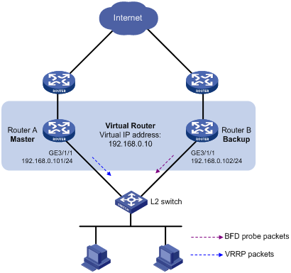
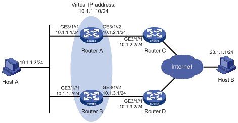
· As shown in Figure 3, Router A and Router B belong to VRRP group 1, whose virtual IP address is 192.168.0.10.
· The default gateway of the hosts in the LAN is 192.168.0.10. When Router A works normally, the hosts in the LAN access the external network through Router A. When Router A fails, the hosts in the LAN access the external network through Router B.
· If BFD is not configured, when the master in a VRRP group fails, the backup cannot become the master until the configured timeout timer expires. The timeout is generally three to four seconds, which makes the switchover slow. To solve this problem, VRRP uses BFD to probe the state of the master. Once the master fails, the backup can become the new master in milliseconds.
Configuration procedure
1. Configure VRRP on Router A:
<RouterA> system-view
[RouterA] interface GigabitEthernet 3/1/1
# Create VRRP group 1, and configure the virtual IP address 192.168.0.10 for the group. Set the priority of Router A in VRRP group 1 to 110.
[RouterA-GigabitEthernet3/1/1] vrrp vrid 1 virtual-ip 192.168.0.10
[RouterA-GigabitEthernet3/1/1] vrrp vrid 1 priority 110
[RouterA-GigabitEthernet3/1/1] return
2. Configure BFD on Router B:
# Configure the source address of BFD echo packets as 10.10.10.10.
<RouterB> system-view
[RouterB] bfd echo-source-ip 10.10.10.10
3. Create a track entry to be associated with the BFD session on Router B:
# Create track entry 1 to be associated with the BFD session to check whether Router A is reachable.
[RouterB] track 1 bfd echo interface GigabitEthernet 3/1/1 remote ip 192.168.0.101 local ip 192.168.0.102
4. Configure VRRP on Router B:
# Create VRRP group 1, and configure the virtual IP address 192.168.0.10 for the group. VRRP group 1 monitors the status of track entry 1. When the status of the track entry becomes Negative, Router B becomes the master quickly.
[RouterB] interface GigabitEthernet 3/1/1
[RouterB-GigabitEthernet3/1/1] vrrp vrid 1 virtual-ip 192.168.0.10
[RouterB-GigabitEthernet3/1/1] vrrp vrid 1 track 1 switchover
[RouterB-GigabitEthernet3/1/1] return
Verifying the configuration
# Display the detailed information of VRRP group 1 on Router A.
<RouterA> display vrrp verbose
IPv4 Standby Information:
Run Mode : Standard
Run Method : Virtual MAC
Total number of virtual routers : 1
Interface GigabitEthernet3/1/1
VRID : 1 Adver Timer : 1
Admin Status : Up State : Master
Config Pri : 110 Running Pri : 110
Preempt Mode : Yes Delay Time : 0
Auth Type : None
Virtual IP : 192.168.0.10
Virtual MAC : 0000-5e00-0101
Master IP : 192.168.0.101
# Display the detailed information of VRRP group 1 on Router B.
<RouterB> display vrrp verbose
IPv4 Standby Information:
Run Mode : Standard
Run Method : Virtual MAC
Total number of virtual routers : 1
Interface GigabitEthernet3/1/1
VRID : 1 Adver Timer : 1
Admin Status : Up State : Backup
Config Pri : 100 Running Pri : 100
Preempt Mode : Yes Delay Time : 0
Auth Type : None
Virtual IP : 192.168.0.10
Master IP : 192.168.0.101
VRRP Track Information:
Track Object : 1 State : Positive Switchover
# Display information about track entry 1 on Router B.
<RouterB> display track 1
Track ID: 1
Status: Positive
Duration: 0 days 0 hours 0 minutes 32 seconds
Notification delay: Positive 0, Negative 0 (in seconds)
Reference object:
BFD session:
Packet type: Echo
Interface : GigabitEthernet3/1/1
Remote IP : 192.168.0.101
Local IP : 192.168.0.102
The output shows that when the status of the track entry becomes Positive, Router A is the master and Router B the backup.
# Enable VRRP state debugging and BFD event debugging on Router B.
<RouterB> terminal debugging
<RouterB> terminal monitor
<RouterB> debugging vrrp state
<RouterB> debugging bfd event
# When Router A fails, the following output is displayed on Router B.
*Dec 17 14:44:34:142 2008 RouterB BFD/7/EVENT:Send sess-down Msg, [Src:192.168.0.102,Dst:192.168.0.101,GigabitEthernet3/1/1,Echo], instance:0, protocol:Track
*Dec 17 14:44:34:144 2008 RouterB VRRP/7/DebugState: IPv4 GigabitEthernet3/1/1 | Virtual Router 1 : Backup --> Master reason: The status of the tracked object changed
# Display the detailed information of the VRRP group on Router B.
<RouterB> display vrrp verbose
IPv4 Standby Information:
Run Mode : Standard
Run Method : Virtual MAC
Total number of virtual routers : 1
Interface GigabitEthernet3/1/1
VRID : 1 Adver Timer : 1
Admin Status : Up State : Master
Config Pri : 100 Running Pri : 100
Preempt Mode : Yes Delay Time : 0
Auth Type : None
Virtual IP : 192.168.0.10
Virtual MAC : 0000-5e00-0101
Master IP : 192.168.0.102
VRRP Track Information:
Track Object : 1 State : Negative Switchover
The output shows that when BFD detects that Router A fails, it notifies VRRP through the track module to change the status of Router B to master, without waiting for a period three times the advertisement interval so that a backup can quickly preempt as the master.
Configuring BFD for the VRRP master to monitor the uplink
Network requirements
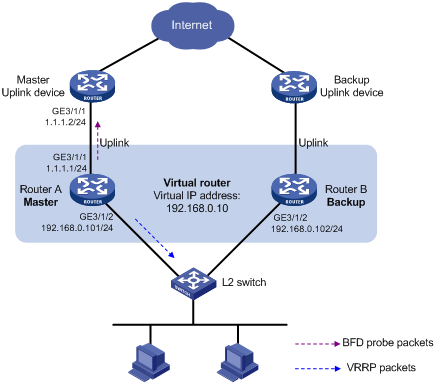
· As shown in Figure 4, Router A and Router B belong to VRRP group 1, whose virtual IP address is 192.168.0.10.
· The default gateway of the hosts in the LAN is 192.168.0.10.
· When Router A works properly, hosts in the LAN access the external network through Router A. When Router A detects that the uplink is down through BFD, it decreases its priority so that Router B can preempt as the master, ensuring that the hosts in the LAN can access the external network through Router B.
Configuration procedure
1. Configure BFD on Router A:
# Configure the source address of BFD echo packets as 10.10.10.10.
<RouterA> system-view
[RouterA] bfd echo-source-ip 10.10.10.10
2. Create the track entry to associate with the BFD session on Router A:
# Create track entry 1 for the BFD session on Router A to check whether the uplink device with the IP address 1.1.1.2 is reachable.
[RouterA] track 1 bfd echo interface GigabitEthernet 3/1/1 remote ip 1.1.1.2 local ip 1.1.1.1
3. Configure VRRP on Router A:
# Create VRRP group 1, and configure the virtual IP address of the group as 192.168.0.10; configure the priority of Router A in VRRP group 1 as 110; configure VRRP group 1 to monitor the status of track entry 1. When the status of the track entry becomes Negative, the priority of Router A decreases by 20.
[RouterA] interface GigabitEthernet 3/1/2
[RouterA-GigabitEthernet3/1/2] vrrp vrid 1 virtual-ip 192.168.0.10
[RouterA-GigabitEthernet3/1/2] vrrp vrid 1 priority 110
[RouterA-GigabitEthernet3/1/2] vrrp vrid 1 track 1 reduced 20
[RouterA-GigabitEthernet3/1/2] return
4. Configure VRRP on Router B:
# Create VRRP group 1, and configure the virtual IP address of the group as 192.168.0.10.
[RouterB] interface GigabitEthernet 3/1/2
[RouterB-GigabitEthernet3/1/2] vrrp vrid 1 virtual-ip 192.168.0.10
[RouterB-GigabitEthernet3/1/2] return
Verifying the configuration
# Display the detailed information of the VRRP group on Router A.
<RouterA> display vrrp verbose
IPv4 Standby Information:
Run Mode : Standard
Run Method : Virtual MAC
Total number of virtual routers : 1
Interface GigabitEthernet3/1/2
VRID : 1 Adver Timer : 1
Admin Status : Up State : Master
Config Pri : 110 Running Pri : 110
Preempt Mode : Yes Delay Time : 0
Auth Type : None
Virtual IP : 192.168.0.10
Virtual MAC : 0000-5e00-0101
Master IP : 192.168.0.101
VRRP Track Information:
Track Object : 1 State : Positive Pri Reduced : 20
# Display the information of track entry 1 on Router A.
<RouterA> display track 1
Track ID: 1
Status: Positive
Duration: 0 days 0 hours 0 minutes 32 seconds
Notification delay: Positive 0, Negative 0 (in seconds)
Reference object:
BFD session:
Packet type: Echo
Interface : GigabitEthernet3/1/1
Remote IP : 1.1.1.2
Local IP : 1.1.1.1
# Display the detailed information of the VRRP group on Router B.
<RouterB> display vrrp verbose
IPv4 Standby Information:
Run Mode : Standard
Run Method : Virtual MAC
Total number of virtual routers : 1
Interface GigabitEthernet3/1/2
VRID : 1 Adver Timer : 1
Admin Status : Up State : Backup
Config Pri : 100 Running Pri : 100
Preempt Mode : Yes Delay Time : 0
Auth Type : None
Virtual IP : 192.168.0.10
Master IP : 192.168.0.101
The output shows that when the status of track entry 1 becomes Positive, Router A is the master and Router B the backup.
# When the uplink of Router A goes down, the status of track entry 1 becomes Negative.
<RouterA> display track 1
Track ID: 1
Status: Negative
Duration: 0 days 0 hours 0 minutes 32 seconds
Notification delay: Positive 0, Negative 0 (in seconds)
Reference object:
BFD session:
Packet type: Echo
Interface : GigabitEthernet3/1/1
Remote IP : 1.1.1.2
Local IP : 1.1.1.1
# Display the detailed information of the VRRP group on Router A.
<RouterA> display vrrp verbose
IPv4 Standby Information:
Run Mode : Standard
Run Method : Virtual MAC
Total number of virtual routers : 1
Interface GigabitEthernet3/1/2
VRID : 1 Adver Timer : 1
Admin Status : Up State : Backup
Config Pri : 110 Running Pri : 90
Preempt Mode : Yes Delay Time : 0
Auth Type : None
Virtual IP : 192.168.0.10
Master IP : 192.168.0.102
VRRP Track Information:
Track Object : 1 State : Negative Pri Reduced : 20
# Display the detailed information of VRRP group 1 on Router B.
<RouterB> display vrrp verbose
IPv4 Standby Information:
Run Mode : Standard
Run Method : Virtual MAC
Total number of virtual routers : 1
Interface GigabitEthernet3/1/2
VRID : 1 Adver Timer : 1
Admin Status : Up State : Master
Config Pri : 100 Running Pri : 100
Preempt Mode : Yes Delay Time : 0
Auth Type : None
Virtual IP : 192.168.0.10
Virtual MAC : 0000-5e00-0101
Master IP : 192.168.0.102
The output shows that when Router A detects that the uplink fails through BFD, it decreases its priority by 20 to guarantee that Router B can preempt as the master.
Static routing-track-NQA collaboration configuration example
Network requirements
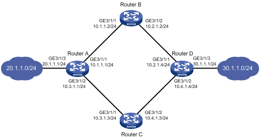
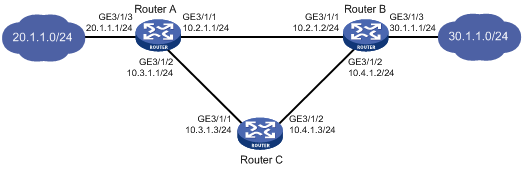
As shown in Figure 5, Router A, Router B, Router C, and Router D are connected to two segments 20.1.1.0/24 and 30.1.1.0/24. Configure static routes on these routers so that the two segments can communicate with each other, and configure route backup to improve reliability of the network.
Router A is the default gateway of the hosts in segment 20.1.1.0/24. Two static routes to 30.1.1.0/24 exist on Router A, with the next hop being Router B and Router C respectively. These two static routes back up each other, where:
· The static route with Router B as the next hop has a higher priority, and is the master route. If this route is available, Router A forwards packets to 30.1.1.0/24 through Router B.
· The static route with Router C as the next hop acts as the backup route.
· Configure static routing-track-NQA collaboration to determine whether the master route is available in real time. If the master route is unavailable, the backup route takes effect, and Router A forwards packets to 30.1.1.0/24 through Router C.
Similarly, Router D is the default gateway of the hosts in segment 30.1.1.0/24. Two static routes to 20.1.1.0/24 exist on Router D, with the next hop being Router B and Router C respectively. These two static routes back up each other, where:
· The static route with Router B as the next hop has a higher priority, and is the master route. If this route is available, Router D forwards packets to 20.1.1.0/24 through Router B.
· The static route with Router C as the next hop acts as the backup route.
· Configure static routing-track-NQA collaboration to determine whether the master route is available in real time. If the master route is unavailable, the backup route takes effect, and Router D forwards packets to 20.1.1.0/24 through Router C.
Configuration procedure
1. Configure the IP address of each interface as shown in Figure 5.
2. Configure Router A:
# Configure a static route to 30.1.1.0/24, with the address of the next hop as 10.1.1.2 and the default priority 60. This static route is associated with track entry 1.
<RouterA> system-view
[RouterA] ip route-static 30.1.1.0 24 10.1.1.2 track 1
# Configure a static route to 30.1.1.0/24, with the address of the next hop as 10.3.1.3 and the priority 80.
[RouterA] ip route-static 30.1.1.0 24 10.3.1.3 preference 80
# Configure a static route to 10.2.1.4, with the address of the next hop as 10.1.1.2.
[RouterA] ip route-static 10.2.1.4 24 10.1.1.2
# Create an NQA test group with the administrator admin and the operation tag test.
[RouterA] nqa entry admin test
# Configure the test type as ICMP-echo.
[RouterA-nqa-admin-test] type icmp-echo
# Configure the destination address of the test as 10.2.1.4 and the next hop address as 10.1.1.2 to check the connectivity of the path from Router A to Router B, and then to Router D through NQA.
[RouterA-nqa-admin-test-icmp-echo] destination ip 10.2.1.4
[RouterA-nqa-admin-test-icmp-echo] next-hop 10.1.1.2
# Configure the test frequency as 100 ms.
[RouterA-nqa-admin-test-icmp-echo] frequency 100
# Configure reaction entry 1, specifying that five consecutive probe failures trigger the track module.
[RouterA-nqa-admin-test-icmp-echo] reaction 1 checked-element probe-fail threshold-type consecutive 5 action-type trigger-only
[RouterA-nqa-admin-test-icmp-echo] quit
# Start the NQA test.
[RouterA] nqa schedule admin test start-time now lifetime forever
# Configure track entry 1, and associate it with reaction entry 1 of the NQA test group (with the administrator admin, and the operation tag test).
[RouterA] track 1 nqa entry admin test reaction 1
3. Configure Router B:
# Configure a static route to 30.1.1.0/24, with the address of the next hop as 10.2.1.4.
<RouterB> system-view
[RouterB] ip route-static 30.1.1.0 24 10.2.1.4
# Configure a static route to 20.1.1.0/24, with the address of the next hop as 10.1.1.1.
[RouterB] ip route-static 20.1.1.0 24 10.1.1.1
4. Configure Router C:
# Configure a static route to 30.1.1.0/24, with the address of the next hop as 10.4.1.4.
<RouterC> system-view
[RouterC] ip route-static 30.1.1.0 24 10.4.1.4
# Configure a static route to 20.1.1.0/24, with the address of the next hop as 10.3.1.1.
[RouterC] ip route-static 20.1.1.0 24 10.3.1.1
5. Configure Router D:
# Configure a static route to 20.1.1.0/24, with the address of the next hop as 10.2.1.2 and the default priority 60. This static route is associated with track entry 1.
<RouterD> system-view
[RouterD] ip route-static 20.1.1.0 24 10.2.1.2 track 1
# Configure a static route to 20.1.1.0/24, with the address of the next hop as 10.4.1.3 and the default priority 80.
[RouterD] ip route-static 20.1.1.0 24 10.4.1.3 preference 80
# Configure a static route to 10.1.1.1, with the address of the next hop as 10.2.1.2.
[RouterD] ip route-static 10.1.1.1 24 10.2.1.2
# Create an NQA test group with the administrator admin and the operation tag test.
[RouterD] nqa entry admin test
# Configure the test type as ICMP-echo.
[RouterD-nqa-admin-test] type icmp-echo
# Configure the destination address of the test as 10.1.1.1 and the next hop address as 10.2.1.2 to check the connectivity of the path from Router D to Router B, and then to Router A through NQA.
[RouterD-nqa-admin-test-icmp-echo] destination ip 10.1.1.1
[RouterD-nqa-admin-test-icmp-echo] next-hop 10.2.1.2
# Configure the test frequency as 100 ms.
[RouterD-nqa-admin-test-icmp-echo] frequency 100
# Configure reaction entry 1, specifying that five consecutive probe failures trigger the track module.
[RouterD-nqa-admin-test-icmp-echo] reaction 1 checked-element probe-fail threshold-type consecutive 5 action-type trigger-only
[RouterD-nqa-admin-test-icmp-echo] quit
# Start the NQA test.
[RouterD] nqa schedule admin test start-time now lifetime forever
# Configure track entry 1, and associate it with reaction entry 1 of the NQA test group (with the administrator admin, and the operation tag test).
[RouterD] track 1 nqa entry admin test reaction 1
Verifying the configuration
# Display information of the track entry on Router A.
[RouterA] display track all
Track ID: 1
Status: Positive
Duration: 0 days 0 hours 0 minutes 32 seconds
Notification delay: Positive 0, Negative 0 (in seconds)
Reference object:
NQA entry: admin test
Reaction: 1
# Display the routing table of Router A.
[RouterA] display ip routing-table
Routing Tables: Public
Destinations : 10 Routes : 10
Destination/Mask Proto Pre Cost NextHop Interface
10.1.1.0/24 Direct 0 0 10.1.1.1 GE3/1/1
10.1.1.1/32 Direct 0 0 127.0.0.1 InLoop0
10.2.1.0/24 Static 60 0 10.1.1.2 GE3/1/1
10.3.1.0/24 Direct 0 0 10.3.1.1 GE3/1/2
10.3.1.1/32 Direct 0 0 127.0.0.1 InLoop0
20.1.1.0/24 Direct 0 0 20.1.1.1 GE3/1/3
20.1.1.1/32 Direct 0 0 127.0.0.1 InLoop0
30.1.1.0/24 Static 60 0 10.1.1.2 GE3/1/1
127.0.0.0/8 Direct 0 0 127.0.0.1 InLoop0
127.0.0.1/32 Direct 0 0 127.0.0.1 InLoop0
The output shows the NQA test result: the master route is available (the status of the track entry is Positive), and Router A forwards packets to 30.1.1.0/24 through Router B.
# Remove the IP address of interface GigabitEthernet 3/1/1 on Router B.
<RouterB> system-view
[RouterB] interface GigabitEthernet 3/1/1
[RouterB-GigabitEthernet3/1/1] undo ip address
# Display information of the track entry on Router A.
[RouterA] display track all
Track ID: 1
Status: Negative
Duration: 0 days 0 hours 0 minutes 32 seconds
Notification delay: Positive 0, Negative 0 (in seconds)
Reference object:
NQA entry: admin test
Reaction: 1
# Display the routing table of Router A.
[RouterA] display ip routing-table
Routing Tables: Public
Destinations : 10 Routes : 10
Destination/Mask Proto Pre Cost NextHop Interface
10.1.1.0/24 Direct 0 0 10.1.1.1 GE3/1/1
10.1.1.1/32 Direct 0 0 127.0.0.1 InLoop0
10.2.1.0/24 Static 60 0 10.1.1.2 GE3/1/1
10.3.1.0/24 Direct 0 0 10.3.1.1 GE3/1/2
10.3.1.1/32 Direct 0 0 127.0.0.1 InLoop0
20.1.1.0/24 Direct 0 0 20.1.1.1 GE3/1/3
20.1.1.1/32 Direct 0 0 127.0.0.1 InLoop0
30.1.1.0/24 Static 80 0 10.3.1.3 GE3/1/2
127.0.0.0/8 Direct 0 0 127.0.0.1 InLoop0
127.0.0.1/32 Direct 0 0 127.0.0.1 InLoop0
The output shows the NQA test result: if the master route is unavailable (the status of the track entry is Negative), the backup static route takes effect and Router A forwards packets to 30.1.1.0/24 through Router C.
# When the master route fails, the hosts in 20.1.1.0/24 can still communicate with the hosts in 30.1.1.0/24.
[RouterA] ping -a 20.1.1.1 30.1.1.1
PING 30.1.1.1: 56 data bytes, press CTRL_C to break
Reply from 30.1.1.1: bytes=56 Sequence=1 ttl=254 time=2 ms
Reply from 30.1.1.1: bytes=56 Sequence=2 ttl=254 time=1 ms
Reply from 30.1.1.1: bytes=56 Sequence=3 ttl=254 time=1 ms
Reply from 30.1.1.1: bytes=56 Sequence=4 ttl=254 time=2 ms
Reply from 30.1.1.1: bytes=56 Sequence=5 ttl=254 time=1 ms
--- 30.1.1.1 ping statistics ---
5 packet(s) transmitted
5 packet(s) received
0.00% packet loss
round-trip min/avg/max = 1/1/2 ms
# The output on Router D is similar to that on Router A. When the master route fails, the hosts in 30.1.1.0/24 can still communicate with the hosts in 20.1.1.0/24.
[RouterD] ping -a 30.1.1.1 20.1.1.1
PING 20.1.1.1: 56 data bytes, press CTRL_C to break
Reply from 20.1.1.1: bytes=56 Sequence=1 ttl=254 time=2 ms
Reply from 20.1.1.1: bytes=56 Sequence=2 ttl=254 time=1 ms
Reply from 20.1.1.1: bytes=56 Sequence=3 ttl=254 time=1 ms
Reply from 20.1.1.1: bytes=56 Sequence=4 ttl=254 time=1 ms
Reply from 20.1.1.1: bytes=56 Sequence=5 ttl=254 time=1 ms
--- 20.1.1.1 ping statistics ---
5 packet(s) transmitted
5 packet(s) received
0.00% packet loss
round-trip min/avg/max = 1/1/2 ms
Static routing-track-BFD collaboration configuration example
Network requirements
As shown in Figure 6, Router A, Router B, and Router C are connected to two segments 20.1.1.0/24 and 30.1.1.0/24. Configure static routes on these routers so that the two segments can communicate with each other, and configure route backup to improve reliability of the network.
Router A is the default gateway of the hosts in segment 20.1.1.0/24. Two static routes to 30.1.1.0/24 exist on Router A, with the next hop being Router B and Router C respectively. These two static routes back up each other, where:
· The static route with Router B as the next hop has a higher priority, and is the master route. If this route is available, Router A forwards packets to 30.1.1.0/24 through Router B.
· The static route with Router C as the next hop acts as the backup route.
· Configure static routing-track-BFD collaboration to determine whether the master route is available in real time. If the master route is unavailable, BFD can quickly detect the route failure to make the backup route take effect, and Router A forwards packets to 30.1.1.0/24 through Router C and Router B.
Similarly, Router B is the default gateway of the hosts in segment 30.1.1.0/24. Two static routes to 20.1.1.0/24 exist on Router B, with the next hop being Router A and Router C respectively. These two static routes back up each other, where:
· The static route with Router A as the next hop has a higher priority, and is the master route. If this route is available, Router B forwards packets to 20.1.1.0/24 through Router A.
· The static route with Router C as the next hop acts as the backup route.
· Configure static routing-track-BFD collaboration to determine whether the master route is available in real time. If the master route is unavailable, BFD can quickly detect the route failure to make the backup route take effect, and Router B forwards packets to 20.1.1.0/24 through Router C and Router A.
Configuration procedure
1. Configure the IP address of each interface as shown in Figure 6. (Details not shown)
2. Configure Router A:
# Configure a static route to 30.1.1.0/24, with the address of the next hop as 10.2.1.2 and the default priority 60. This static route is associated with track entry 1.
<RouterA> system-view
[RouterA] ip route-static 30.1.1.0 24 10.2.1.2 track 1
# Configure a static route to 30.1.1.0/24, with the address of the next hop as 10.3.1.3 and the priority 80.
[RouterA] ip route-static 30.1.1.0 24 10.3.1.3 preference 80
# Configure the source address of BFD echo packets as 10.10.10.10.
[RouterA] bfd echo-source-ip 10.10.10.10
# Configure track entry 1, and associate it with the BFD session. Check whether Router A can be interoperated with the next hop of static route: Router B.
[RouterA] track 1 bfd echo interface GigabitEthernet 3/1/1 remote ip 10.2.1.2 local ip 10.2.1.1
3. Configure Router B:
# Configure a static route to 20.1.1.0/24, with the address of the next hop as 10.2.1.1 and the default priority 60. This static route is associated with track entry 1.
<RouterB> system-view
[RouterB] ip route-static 20.1.1.0 24 10.2.1.1 track 1
# Configure a static route to 20.1.1.0/24, with the address of the next hop as 10.4.1.3 and the priority 80.
[RouterB] ip route-static 20.1.1.0 24 10.4.1.3 preference 80
# Configure the source address of BFD echo packets as 1.1.1.1.
[RouterB] bfd echo-source-ip 1.1.1.1
# Configure track entry 1 that is associated with the BFD session to check whether Router A can communicate with the next hop Router B of the static route.
[RouterB] track 1 bfd echo interface GigabitEthernet 3/1/1 remote ip 10.2.1.1 local ip 10.2.1.2
4. Configure Router C:
# Configure a static route to 30.1.1.0/24, with the address of the next hop as 10.4.1.2.
<RouterC> system-view
[RouterC] ip route-static 30.1.1.0 24 10.4.1.2
# Configure a static route to 20.1.1.0/24, with the address of the next hop as 10.3.1.1.
[RouterB] ip route-static 20.1.1.0 24 10.3.1.1
Verifying the configuration
# Display information of the track entry on Router A.
[RouterA] display track all
Track ID: 1
Status: Positive
Duration: 0 days 0 hours 0 minutes 32 seconds
Notification delay: Positive 0, Negative 0 (in seconds)
Reference object:
BFD Session:
Packet type: Echo
Interface : GigabitEthernet3/1/1
Remote IP : 10.2.1.2
Local IP : 10.2.1.1
# Display the routing table of Router A.
[RouterA] display ip routing-table
Routing Tables: Public
Destinations : 9 Routes : 9
Destination/Mask Proto Pre Cost NextHop Interface
10.2.1.0/24 Direct 0 0 10.2.1.1 GE3/1/1
10.2.1.1/32 Direct 0 0 127.0.0.1 InLoop0
10.3.1.0/24 Direct 0 0 10.3.1.1 GE3/1/2
10.3.1.1/32 Direct 0 0 127.0.0.1 InLoop0
20.1.1.0/24 Direct 0 0 20.1.1.1 GE3/1/3
20.1.1.1/32 Direct 0 0 127.0.0.1 InLoop0
30.1.1.0/24 Static 60 0 10.2.1.2 GE3/1/1
127.0.0.0/8 Direct 0 0 127.0.0.1 InLoop0
127.0.0.1/32 Direct 0 0 127.0.0.1 InLoop0
The output shows the BFD detection result: the next hop 10.2.1.2 is reachable (the status of the track entry is Positive), and the master static route takes effect. Router A forwards packets to 30.1.1.0/24 through Router B.
# Remove the IP address of interface GigabitEthernet 3/1/1 on Router B.
<RouterB> system-view
[RouterB] interface GigabitEthernet 3/1/1
[RouterB-GigabitEthernet3/1/1] undo ip address
# Display information of the track entry on Router A.
[RouterA] display track all
Track ID: 1
Status: Negative
Duration: 0 days 0 hours 0 minutes 32 seconds
Notification delay: Positive 0, Negative 0 (in seconds)
Reference object:
BFD Session:
Packet type: Echo
Interface : GigabitEthernet3/1/1
Remote IP : 10.2.1.2
Local IP : 10.2.1.1
# Display the routing table of Router A.
[RouterA] display ip routing-table
Routing Tables: Public
Destinations : 9 Routes : 9
Destination/Mask Proto Pre Cost NextHop Interface
10.2.1.0/24 Direct 0 0 10.2.1.1 GE3/1/1
10.2.1.1/32 Direct 0 0 127.0.0.1 InLoop0
10.3.1.0/24 Direct 0 0 10.3.1.1 GE3/1/2
10.3.1.1/32 Direct 0 0 127.0.0.1 InLoop0
20.1.1.0/24 Direct 0 0 20.1.1.1 GE3/1/3
20.1.1.1/32 Direct 0 0 127.0.0.1 InLoop0
30.1.1.0/24 Static 80 0 10.3.1.3 GE3/1/2
127.0.0.0/8 Direct 0 0 127.0.0.1 InLoop0
127.0.0.1/32 Direct 0 0 127.0.0.1 InLoop0
The output shows the BFD detection result: if the next hop 10.2.1.2 is unreachable (the status of the track entry is Negative), the backup static route takes effect, and Router A forwards packets to 30.1.1.0/24 through Router C and Router B.
# When the master route fails, the hosts in 20.1.1.0/24 can still communicate with the hosts in 30.1.1.0/24.
[RouterA] ping -a 20.1.1.1 30.1.1.1
PING 30.1.1.1: 56 data bytes, press CTRL_C to break
Reply from 30.1.1.1: bytes=56 Sequence=1 ttl=254 time=2 ms
Reply from 30.1.1.1: bytes=56 Sequence=2 ttl=254 time=1 ms
Reply from 30.1.1.1: bytes=56 Sequence=3 ttl=254 time=1 ms
Reply from 30.1.1.1: bytes=56 Sequence=4 ttl=254 time=2 ms
Reply from 30.1.1.1: bytes=56 Sequence=5 ttl=254 time=1 ms
--- 30.1.1.1 ping statistics ---
5 packet(s) transmitted
5 packet(s) received
0.00% packet loss
round-trip min/avg/max = 1/1/2 ms
# The output on Router B is similar to that on Router A. When the master route fails, the hosts in 30.1.1.0/24 can still communicate with the hosts in 20.1.1.0/24.
[RouterB] ping -a 30.1.1.1 20.1.1.1
PING 20.1.1.1: 56 data bytes, press CTRL_C to break
Reply from 20.1.1.1: bytes=56 Sequence=1 ttl=254 time=2 ms
Reply from 20.1.1.1: bytes=56 Sequence=2 ttl=254 time=1 ms
Reply from 20.1.1.1: bytes=56 Sequence=3 ttl=254 time=1 ms
Reply from 20.1.1.1: bytes=56 Sequence=4 ttl=254 time=1 ms
Reply from 20.1.1.1: bytes=56 Sequence=5 ttl=254 time=1 ms
--- 20.1.1.1 ping statistics ---
5 packet(s) transmitted
5 packet(s) received
0.00% packet loss
round-trip min/avg/max = 1/1/2 ms
VRRP-track-interface management collaboration configuration example (the master monitors the uplink interface)
Network requirements
· As shown in Figure 7, Host A needs to access Host B on the Internet. The default gateway of Host A is 10.1.1.10/24.
· Router A and Router B belong to VRRP group 1, whose virtual IP address is 10.1.1.10.
· When Router A works normally, packets from Host A to Host B are forwarded through Router A. When VRRP detects that a fault is on the uplink interface of Router A through the interface management module, packets from Host A to Host B are forwarded through Router B.
Configuration procedure
1. Configure the IP address of each interface as shown in Figure 7.
2. Configure a track entry on Router A:
# Configure track entry 1, and associate it with the physical status of the uplink interface GigabitEthernet 3/1/2.
[RouterA] track 1 interface GigabitEthernet 3/1/2
3. Configure VRRP on Router A:
# Create VRRP group 1, and configure the virtual IP address 10.1.1.10 for the group.
[RouterA] interface GigabitEthernet 3/1/1
[RouterA-GigabitEthernet3/1/1] vrrp vrid 1 virtual-ip 10.1.1.10
# Set the priority of Router A in VRRP group 1 to 110.
[RouterA-GigabitEthernet3/1/1] vrrp vrid 1 priority 110
# Configure to monitor track entry 1 and specify the priority decrement as 30.
[RouterA-GigabitEthernet3/1/1] vrrp vrid 1 track 1 reduced 30
4. Configure VRRP on Router B:
<RouterB> system-view
[RouterB] interface GigabitEthernet 3/1/1
# Create VRRP group 1, and configure the virtual IP address 10.1.1.10 for the group.
[RouterB-GigabitEthernet3/1/1] vrrp vrid 1 virtual-ip 10.1.1.10
Verifying the configuration
After configuration, ping Host B on Host A, and you can see that Host B is reachable. Use the display vrrp command to view the configuration result.
# Display detailed information about VRRP group 1 on Router A.
[RouterA-GigabitEthernet3/1/1] display vrrp verbose
IPv4 Standby Information:
Run Mode : Standard
Run Method : Virtual MAC
Total number of virtual routers : 1
Interface GigabitEthernet3/1/1
VRID : 1 Adver Timer : 1
Admin Status : Up State : Master
Config Pri : 110 Running Pri : 110
Preempt Mode : Yes Delay Time : 0
Auth Type : None
Virtual IP : 10.1.1.10
Virtual MAC : 0000-5e00-0101
Master IP : 10.1.1.1
VRRP Track Information:
Track Object : 1 State : Positive Pri Reduced : 30
# Display detailed information about VRRP group 1 on Router B.
[RouterB-GigabitEthernet3/1/1] display vrrp verbose
IPv4 Standby Information:
Run Mode : Standard
Run Method : Virtual MAC
Total number of virtual routers : 1
Interface GigabitEthernet3/1/1
VRID : 1 Adver Timer : 1
Admin Status : Up State : Backup
Config Pri : 100 Running Pri : 100
Preempt Mode : Yes Delay Time : 0
Auth Type : None
Virtual IP : 10.1.1.10
Master IP : 10.1.1.1
The output shows that in VRRP group 1, Router A is the master and Router B is a backup. Packets from Host A to Host B are forwarded through Router A.
# Shut down the uplink interface GigabitEthernet 3/1/2 on Router A.
[RouterA-GigabitEthernet3/1/1] interface GigabitEthernet 3/1/2
[RouterA-GigabitEthernet3/1/2] shutdown
After shutting down the uplink interface on Router A, you can still successfully ping Host B on Host A. Use the display vrrp command to view information about VRRP group 1.
# After shutting down the uplink interface on Router A, display detailed information about VRRP group 1 on Router A.
[RouterA-GigabitEthernet3/1/2] display vrrp verbose
IPv4 Standby Information:
Run Mode : Standard
Run Method : Virtual MAC
Total number of virtual routers : 1
Interface GigabitEthernet3/1/1
VRID : 1 Adver Timer : 1
Admin Status : Up State : Backup
Config Pri : 110 Running Pri : 80
Preempt Mode : Yes Delay Time : 0
Auth Type : None
Virtual IP : 10.1.1.10
Master IP : 10.1.1.2
VRRP Track Information:
Track Object : 1 State : Negative Pri Reduced : 30
# After shutting down the uplink interface on Router A, display detailed information about VRRP group 1 on Router B.
[RouterB-GigabitEthernet3/1/1] display vrrp verbose
IPv4 Standby Information:
Run Mode : Standard
Run Method : Virtual MAC
Total number of virtual routers : 1
Interface GigabitEthernet3/1/1
VRID : 1 Adver Timer : 1
Admin Status : Up State : Master
Config Pri : 100 Running Pri : 100
Preempt Mode : Yes Delay Time : 0
Auth Type : None
Virtual IP : 10.1.1.10
Virtual MAC : 0000-5e00-0101
Master IP : 10.1.1.2
The output shows that when the uplink interface on Router A is shut down, the priority of Router A decreases to 80. Router A becomes the backup, and Router B becomes the master. Packets from Host A to Host B are forwarded through Router B.