- Table of Contents
- Related Documents
-
| Title | Size | Download |
|---|---|---|
| 06-BFD Configuration | 169.21 KB |
|
|
NOTE: The term router in this document refers to both routers and Layer 3 switches. |
Introduction to BFD
Routers must quickly detect communication failures so that measures can be taken in time to ensure service continuity and enhance network availability.
The main fault detection methods include the following:
· Hardware detection—Detects link failures by sending hardware detection signals, such as synchronous digital hierarchy (SDH) alarms. Hardware detection can quickly detect link failures, but not all media types support hardware detection.
· Hello mechanism—Routers can use the hello mechanism of a routing protocol to detect link failures. The hello mechanism needs seconds to detect a link failure. On a high-speed interface, such as a Gigabit interface, a failure that lasts for one second will cause a large quantity of data to be dropped. The hello mechanism is unacceptable for delay-sensitive services such as voice service. Moreover, this detection method largely relies on the routing protocol.
· Other detection methods—Some protocols provide dedicated detection mechanisms, which however, cannot be deployed for inter-system communications.
Bidirectional forwarding detection (BFD) provides a single mechanism to monitor links. With BFD, routers can quickly detect communication failures and restore communications through backup paths.
How BFD works
BFD provides a general-purpose, standard, medium- and protocol-independent fast failure detection mechanism. It can uniformly and quickly detect the failures of the bidirectional forwarding paths between two routers for protocols, such as routing protocols and Multiprotocol Label Switching (MPLS).
BFD provides no neighbor discovery mechanism. Protocols that BFD services notify BFD of routers to which it needs to establish sessions. After a session is established, if no BFD control packet is received from the peer within the negotiated BFD interval, BFD notifies a failure to the protocol, which takes appropriate measures.
Operation of BFD
Figure 1 BFD session establishment (on OSPF routers)
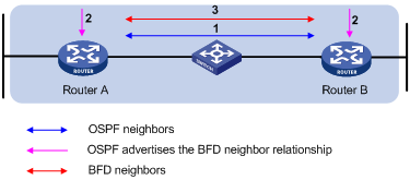
BFD session establishment:
1. A protocol sends Hello messages to discover neighbors and establish neighborships.
2. After establishing neighborships, the protocol notifies BFD of the neighbor information, including destination and source addresses.
3. BFD uses the information to establish BFD sessions.
Figure 2 BFD fault detection (on OSPF routers)
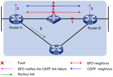
BFD fault detection (as shown in the above figure):
1. BFD detects a link failure.
2. BFD clears the neighbor session.
3. BFD notifies the protocol of the failure.
4. The protocol terminates the neighborship on the link.
5. If a backup link is available, the protocol will use it to forward packets.
|
|
NOTE: No detection time resolution is defined in the BFD draft. Most devices supporting BFD provide detection measured in milliseconds. |
BFD detection methods
· Single-hop detection—Detects the IP connectivity between two directly connected systems.
· Multi-hop detection—Detects any of the paths between two systems. These paths have multiple hops and may be overlapped.
· Bidirectional detection—Sends detection packets at two sides of a bidirectional link to detect the bidirectional link status, finding link failures in milliseconds. (BFD LSP detection is a special case, in which BFD control packets are sent in one direction, and the peer router reports the link status through other links.)
BFD session modes
· Control packet mode—Both ends of the link exchange BFD control packets to monitor link status.
· Echo mode—One end of the link sends Echo packets to the other end, which then forwards the packets back to the originating end, monitoring link status in both directions.
BFD operating modes
Before a BFD session is established, BFD has the following operating modes:
· Active mode—BFD actively sends BFD control packets regardless of whether any BFD control packet is received from the peer.
· Passive mode—BFD does not send control packets until a BFD control packet is received from the peer.
At least one end must operate in the active mode for a BFD session to be established.
After a BFD session is established, both ends must operate in one of the following BFD operating modes:
· Asynchronous mode—Both endpoints periodically send BFD control packets to each other. BFD considers that the session is down if it receives no BFD control packets within a specific interval.
· Demand mode—No BFD control packets are exchanged after the session is established. It is assumed that the endpoints have another way to verify connectivity to each other. However, either host may still send BFD control packets if needed.
|
|
NOTE: · Only the asynchronous mode is supported. · When a BFD session is maintained by sending Echo packets, the session is independent of the operating mode. · When the connectivity to another system needs to be verified explicitly, a system sends several BFD control packets that have the Poll (P) bit set at the negotiated transmit interval. If no response is received within the detection interval, the session is considered down. If the connectivity is found to be up, no more BFD control packets are sent until the next command is issued. |
Dynamic BFD parameter changes
Authentication modes
BFD provides the following authentication methods:
· Simple—Plain text authentication
· MD5—MD5 (Message Digest 5) authentication
· SHA1—SHA1 (Secure Hash Algorithm 1) authentication
|
|
NOTE: BFD authentication is not supported on the router. |
BFD packet format
BFD control packets are encapsulated into UDP packets with port number 3784 for single-hop detection or port number 4784 for multi-hop detection (also can be 3784 based on the configuration task). BFD echo packets have a similar format as BFD control packets (except that the Desired Min TX Interval and Required Min RX Interval fields are null) with UDP port number 3785.
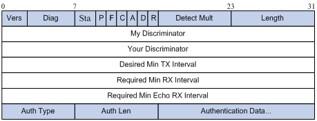
· Vers—Protocol version. The protocol version is 1.
· Diag—This bit indicates the reason for the last transition of the local session from up to some other state. Table 1 lists the states.
Table 1 Diag bit values
|
Diag |
Description |
|
0 |
No Diagnostic |
|
1 |
Control Detection Time Expired |
|
2 |
Echo Function Failed |
|
3 |
Neighbor Signaled Session Down |
|
4 |
Forwarding Plane Reset |
|
5 |
Path Down |
|
6 |
Concatenated Path Down |
|
7 |
Administratively Down |
|
8 |
Reverse Concatenated Path Down |
|
9~31 |
Reserved for future use |
· State (Sta)—Current BFD session state. Its value can be 0 for AdminDown, 1 for Down, 2 for Init, and 3 for Up.
· Poll (P)—If set, the transmitting system is requesting verification of connectivity, or of a parameter change. If clear, the transmitting system is not requesting verification.
· Final (F)—If set, the transmitting system is responding to a received BFD control packet that had the Poll (P) bit set. If clear, the transmitting system is not responding to a Poll.
· Control Plane Independent(C)—If set, the transmitting system's BFD implementation does not share fate with its control plane (BFD is implemented in the forwarding plane and can continue to function through disruptions in the control plane.) If clear, the transmitting system's BFD implementation shares fate with its control plane.
· Authentication Present (A)—If set, the Authentication Section is present and the session is to be authenticated.
· Demand (D)—If set, Demand mode is active in the transmitting system (the system wishes to operate in Demand mode, knows that the session is up in both directions, and is directing the remote system to cease the periodic transmission of BFD Control packets). If clear, Demand mode is not active in the transmitting system.
· Reserved (R)—This byte must be set to zero on transmit, and ignored on receipt.
· Detect Mult—Detection time multiplier.
· Length—Length of the BFD control packet, in bytes.
· My Discriminator—A unique, nonzero discriminator value generated by the transmitting system, used to demultiplex multiple BFD sessions between the same pair of systems.
· Your Discriminator—It is the discriminator received from the remote system. This field reflects back the received value of My Discriminator, or is 0 if that value is unknown.
· Desired Min TX Interval—This is the minimum interval, in microseconds, that the local system would like to use when transmitting BFD control packets. The value zero is reserved.
· Required Min RX Interval—This is the minimum interval, in microseconds, between received BFD control packets that this system is capable of supporting. If this value is zero, the transmitting system does not want the remote system to send any periodic BFD control packets.
· Required Min Echo RX Interval—This is the minimum interval, in microseconds, between received BFD echo packets that this system is capable of supporting. If this value is zero, the transmitting system does not support the receipt of BFD echo packets.
· Auth Type—The authentication type in use, if the Authentication Present (A) bit is set.
Supported features
· OSPF. For more information, see Layer 3—IP Routing Configuration Guide.
· OSPFv3. For more information, see Layer 3—IP Routing Configuration Guide.
· IS-IS. For more information, see Layer 3—IP Routing Configuration Guide.
· IPv6 IS-IS. For more information, see Layer 3—IP Routing Configuration Guide.
· RIP. For more information, see Layer 3—IP Routing Configuration Guide.
· Static routing. For more information, see Layer 3—IP Routing Configuration Guide.
· BGP. For more information, see Layer 3—IP Routing Configuration Guide.
· IPv6 BGP. For more information, see Layer 3—IP Routing Configuration Guide.
· PIM. For more information, see IP Multicast Configuration Guide.
· IPv6 PIM. For more information, see IP Multicast Configuration Guide.
· MPLS. For more information, see MPLS Configuration Guide.
· Track. For more information, see the chapter “Configuring track.”
· IP fast reroute (FRR). Currently, IP FRR is supported by OSPF, RIP, IS-IS and static routing. For more information, see Layer 3—IP Routing Configuration Guide.
Protocols and standards
· draft-ietf-bfd-base-09, Protocol Independent Bidirectional Forwarding Detection
· draft-ietf-bfd-v4v6-1hop-10, BFD for IPv4 and IPv6 (Single Hop)
· draft-ietf-bfd-multihop-08, BFD for Multihop Paths
· draft-ietf-bfd-generic-05, Generic Application of BFD
Configuring BFD basic functions
The BFD basic function configuration is the basis for configuring BFD for other protocols.
Configuration prerequisites
Before configuring BFD basic functions, complete the following tasks:
· Configure the network layer addresses of the interfaces so that adjacent nodes are reachable to each other at the network layer
· Configure the routing protocols that support BFD
Configuration procedure
To configure BFD basic functions:
|
Step |
Command |
Remarks |
|
1. Enter system view. |
system-view |
N/A |
|
2. Specify the mode for establishing a BFD session. |
bfd session init-mode { active | passive } |
Optional. active by default. |
|
3. Configure the destination port number for multi-hop BFD control packets. |
bfd multi-hop destination-port port-number |
Optional. 4784 by default. |
|
4. Configure the source IP address of echo packets. |
bfd echo-source-ip ip-address |
Optional. The source IP address should not be on the same network segment as any local interface’s IP address. Otherwise, a large number of ICMP redirect packets may be sent from the peer, resulting in link congestion. |
|
5. Enter interface view. |
interface interface-type interface-number |
N/A |
|
6. Configure the minimum interval for receiving BFD echo packets. |
bfd min-echo-receive-interval value |
Optional. 400 milliseconds by default. |
|
7. Configure the minimum interval for transmitting BFD control packets. |
bfd min-transmit-interval value |
Optional. 400 milliseconds by default. |
|
8. Configure the minimum interval for receiving BFD control packets. |
bfd min-receive-interval value |
Optional. 400 milliseconds by default. |
|
9. Configure the detection time multiplier. |
bfd detect-multiplier value |
Optional. 5 by default. |
In Figure 1 for example, if you configure the Desired Min TX Interval as 100 milliseconds, Required Min RX Interval as 300 milliseconds, and Detect Mult as 5 on Router A, and configure the Desired Min TX Interval as 150 milliseconds, Required Min RX Interval as 400 milliseconds, and Detect Mult as 10 on Router B,
· The actual transmitting interval on Router A is 400 milliseconds, which is the greater value between the minimum interval for transmitting BFD control packets on Router A (100 milliseconds) and the minimum interval for receiving BFD control packets on Router B (400 milliseconds).
· The actual transmitting interval on Router B is 300 milliseconds, which is the greater value between the minimum interval for transmitting BFD control packets on Router B (150 milliseconds) and the minimum interval for receiving BFD control packets on Router A (300 milliseconds).
· The actual detection time on Router A is 3000 milliseconds, which is 10 × 300 milliseconds (Detect Mult on Router B × actual transmitting interval on Router B).
· The actual detection time on Router B is 2000 milliseconds, which is 5 × 400 milliseconds (Detect Mult on Router A × actual transmitting interval on Router A).
|
|
NOTE: · At least one end must operate in the active mode for a BFD session to be established. · On an aggregate interface having two or more member ports, H3C recommends configuring the link-delay 0 or link-delay milliseconds 0 command on the member ports so that any port state (up or down) change does not impact the BFD session. |
Enabling trap
When the trap function is enabled on the BFD module, the module will generate trap messages at the notifications level to report the important events of the module. The generated trap messages are sent to the router's information center, which determines the output rules for the trap messages (whether to output the trap messages and the output destinations).
To enable BFD trap:
|
Step |
Command |
Remarks |
|
1. Enter system view. |
system-view |
N/A |
|
2. Enable BFD trap. |
snmp-agent trap enable bfd |
Optional Enabled by default |
|
|
NOTE: · For the description of the snmp-agent trap enable bfd command, see the snmp-agent trap enable command in Network Management and Monitoring Command Reference. · For the information center configuration, see Network Management and Monitoring Configuration Guide. |
Displaying and maintaining BFD
|
Task |
Command |
Remarks |
|
Display information about BFD-enabled interfaces. |
display bfd interface [ verbose ] [ | { begin | exclude | include } regular-expression ] |
Available in any view |
|
Display information about enabled BFD debugging. |
display bfd debugging-switches [ | { begin | exclude | include } regular-expression ] |
Available in any view |
|
Display BFD session information. |
display bfd session [ slot slot-number [ all | verbose ] | verbose ] [ | { begin | exclude | include } regular-expression ] |
Available in any view |
|
Clear BFD session statistics. |
reset bfd session statistics [ slot slot-number ] |
Available in user view |