- Table of Contents
- Related Documents
-
| Title | Size | Download |
|---|---|---|
| 05-VRRP Configuration | 623.8 KB |
Contents
VRRP application (taking IPv4-based VRRP for example)
Assigning virtual MAC addresses
VRRP for IPv4 configuration task list
Configuring a VRRP working mode
Specifying the type of MAC addresses mapped to virtual IP addresses
Specifying the VRRP control VLAN
Creating a VRRP group and configuring virtual IP address
Configuring router priority, preemptive mode and tracking function
Configuring VRRP packet attributes
Enabling the trap function for VRRP
Displaying and maintaining VRRP for IPv4
VRRP for IPv6 configuration task list
Specifying the type of MAC addresses mapped to virtual IPv6 addresses
Creating a VRRP group and configuring a virtual IPv6 address
Configuring router priority, preemptive mode and tracking function
Configuring VRRP packet attributes
Displaying and maintaining VRRP for IPv6
IPv4-based VRRP configuration examples
Single VRRP group configuration example
VRRP interface tracking configuration example
Multiple VRRP groups configuration example
VRRP load balancing mode configuration example
IPv6-based VRRP configuration examples
Single VRRP group configuration example
VRRP interface tracking configuration example
Multiple VRRP groups configuration example
|
|
NOTE: · The term router in this document refers to both routers and Layer 3 switches. · The interfaces that VRRP involves can be only Layer 3 Ethernet interfaces/subinterfaces, VLAN interfaces, Layer 3 aggregate interfaces/subinterfaces, and RPR logical interfaces unless otherwise specified. · VRRP cannot be configured on an interface of an aggregation group. |
VRRP overview
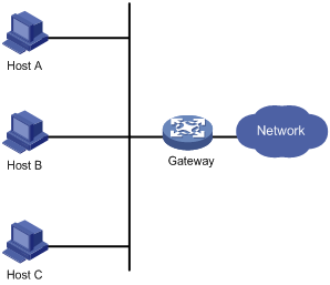
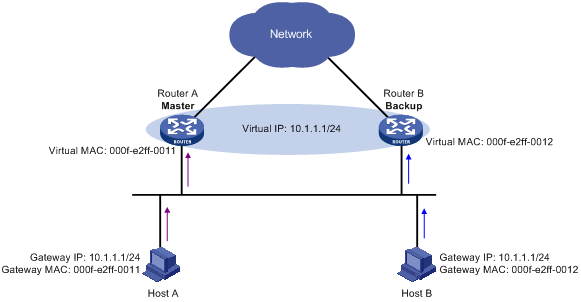
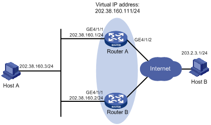
Typically, as shown in Figure 1, you can configure a default route with the gateway as the next hop for every host on a network segment. All packets destined to other network segments are sent over the default route to the gateway, which then forwards the packets. However, when the gateway fails, all the hosts that use the gateway as the default next-hop router fail to communicate with external networks.
Configuring a default route for network hosts facilitates your configuration, but also requires high performance stability of the device that acts as the gateway. Using more egress gateways is a common way to improve system reliability, but introduces the problem of routing among the egresses.
Virtual Router Redundancy Protocol (VRRP) is designed to address this problem. VRRP adds a group of routers that can act as network gateways to a VRRP group, which forms a virtual router. Routers in the VRRP group elect a master through the VRRP election mechanism to act as a gateway, and hosts on a LAN only need to configure the virtual router as their default network gateway.
VRRP is an error-tolerant protocol, which improves the network reliability and simplifies configurations on hosts. On a multicast and broadcast LAN such as Ethernet, VRRP provides highly reliable default links without configuration changes (such as dynamic routing protocols, route discovery protocols) when a router fails, and prevent network interruption due to a single link failure.
VRRP works in either of the following modes:
· Standard protocol mode—Includes two versions VRRPv2 and VRRPv3 based on RFCs. VRRPv2 is based on IPv4, and VRRPv3 is based on IPv6. The two versions implement the same functions but are applied in different network environments. For more information, see VRRP standard protocol mode.
· Load balancing mode—Extends the standard protocol mode and realizes load balancing. For more information, see VRRP load balancing mode.
VRRP standard protocol mode
Introduction to VRRP group
VRRP combines a group of routers (including a master and multiple backups) on a LAN into a virtual router called VRRP group.
A VRRP group has the following features:
· A virtual router has a virtual IP address. A host on the LAN only needs to know the IP address of the virtual router and uses the IP address as the next hop of the default route.
· Every host on the LAN communicates with external networks through the virtual router.
· Routers in the VRRP group elect a master that acts as the gateway according to their priorities. The other routers function as the backups. When the master fails, to make sure that the hosts in the network segment can uninterruptedly communicate with the external networks, the backups in the VRRP group elect a new gateway to undertake the responsibility of the failed master.
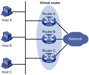
As shown in Figure 2, Router A, Router B, and Router C form a virtual router, which has its own IP address. Hosts on the Ethernet use the virtual router as the default gateway.
The router with the highest priority among the three routers is elected as the master to act as the gateway, and the other two are backups.
|
|
NOTE: · The IP address of the virtual router can be either an unused IP address on the segment where the VRRP group resides or the IP address of an interface on a router in the VRRP group. In the latter case, the router is called the IP address owner. · Only one IP address owner can be configured for a VRRP group. · Status of a router in a VRRP group includes master, backup, and initialize. |
VRRP priority
VRRP determines the role (master or backup) of each router in a VRRP group by priority. A router with a higher priority is more likely to become the master.
VRRP priority is in the range of 0 to 255. The greater the number, the higher the priority. Priorities 1 to 254 are configurable. Priority 0 is reserved for special uses and priority 255 for the IP address owner. When a router acts as the IP address owner, its running priority is always 255. That is, the IP address owner in a VRRP group acts as the master as long as it works properly.
Working mode
A router in a VRRP group works in either of the following modes:
· Non-preemptive mode—When a router in the VRRP group becomes the master, it stays as the master as long as it operates normally, even if a backup is assigned a higher priority later.
· Preemptive mode—When a backup finds its priority higher than that of the master, the backup sends VRRP advertisements to start a new master election in the VRRP group and becomes the master. Accordingly, the original master becomes a backup.
Authentication mode
To avoid attacks from unauthorized users, VRRP adds authentication keys into packets for authentication. VRRP provides the following authentication modes:
· simple—Simple text authentication
A router sending a packet fills an authentication key into the packet, and the router receiving the packet compares its local authentication key with that of the received packet. If the two authentication keys are the same, the received VRRP packet is considered legitimate. Otherwise, the received packet is considered invalid.
· md5—MD5 authentication
A router computes the digest of a packet to be sent by using the authentication key and MD5 algorithm and saves the result in the authentication header. The router that receives the packet performs the same operation by using the authentication key and MD5 algorithm, and compares the result with the content in the authentication header. If the results are the same, the router that receives the packet considers the packet an authentic and valid VRRP packet. Otherwise, the router considers the packet invalid.
On a secure network, you can choose not to set the authentication mode.
VRRP timers
VRRP timers include VRRP advertisement interval timer and VRRP preemption delay timer.
VRRP advertisement interval timer
The master in a VRRP group periodically sends VRRP advertisements to inform the other routers in the VRRP group that it operates properly.
You can adjust the interval for sending VRRP advertisements by setting the VRRP advertisement interval timer. If a backup receives no advertisements in a period three times the interval, the backup regards itself as the master and sends VRRP advertisements to start a new master election.
VRRP preemption delay timer
To avoid frequent state changes among members in a VRRP group and provide the backups enough time to collect information (such as routing information), each backup waits for a period of time (the preemption delay time) after it receives an advertisement with the priority lower than the local priority, then sends VRRP advertisements to start a new master election in the VRRP group and becomes the master.
Packet format
The master multicasts VRRP packets periodically to declare its existence. VRRP packets are also used for checking the parameters of the virtual router and electing the master.
VRRP packets are encapsulated in IP packets, with the protocol number being 112.
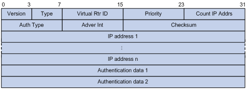
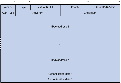
A VRRP packet comprises the following fields:
· Version—Version number of the protocol, 2 for VRRPv2 and 3 for VRRPv3.
· Type—Type of the VRRPv2 or VRRPv3 packet. Only one VRRP packet type is present, that is, VRRP advertisement, which is represented by 1.
· Virtual Rtr ID (VRID)—ID of the virtual router, that is, ID of the VRRP group. It ranges from 1 to 255.
· Priority—Priority of the router in the VRRP group, in the range 0 to 255. A greater value represents a higher priority.
· Count IP Addrs/Count IPv6 Addrs—Number of virtual IPv4 or IPv6 addresses for the VRRP group. A VRRP group can have multiple virtual IPv4 or IPv6 addresses.
· Auth Type—Authentication type. 0 means no authentication, 1 means simple text authentication, and 2 means MD5 authentication. VRRPv3 does not support MD5 authentication.
· Adver Int—Interval for sending advertisement packets. For VRRPv2, the interval is in seconds and defaults to 1. For VRRPv3, the interval is in centiseconds and defaults to 100.
· Checksum—16-bit checksum for validating the data in VRRP packets.
· IP Address/IPv6 Address—Virtual IPv4 or IPv6 address entry of the VRRP group. The Count IP Addrs or Count IPv6 Addrs field defines the number of the virtual IP v4 or IPv6 addresses.
· Authentication Data—Authentication key. This field is used only for simple authentication and is 0 for any other authentication modes.
Principles of VRRP
· Routers in a VRRP group determine their roles by their priorities. The router with the highest priority is the master, and the others are the backups. The master periodically sends VRRP advertisements to notify the backups that it is working properly, and each of the backups starts a timer to wait for advertisements from the master.
· In preemptive mode, when a backup receives a VRRP advertisement, it compares the priority in the packet with its own priority. If the priority of the backup is higher, the backup becomes the master. Otherwise, it remains as a backup. With the preemptive mode, a VRRP group always has a router with the highest priority as the master for packet forwarding.
· In non-preemptive mode, a router in the VRRP group remains as a master or backup as long as the master does not fail. A backup does not become the master even if it is configured with a higher priority. The non-preemptive mode helps avoid frequent switchover between the master and backups.
· If the timer of a backup expires but the backup still does not receive any VRRP advertisement, it considers that the master fails. In this case, the backup considers itself as the master and sends VRRP advertisements to start a new master election.
|
|
NOTE: · Because the VRRP group configuration might be different on routers, and network problems might exist, multiple master routers might exist in one VRRP group. These master routers will elect one master according to their priorities and IP addresses. The router with the highest priority wins the election. If a tie exists in the priority, the router with the largest IP address wins. · After a backup router receives an advertisement, it compares its priority against that carried in the advertisement. If its priority is higher than that carried in the advertisement, it takes over the master. |
VRRP tracking
|
|
NOTE: To enable the VRRP tracking function, configure the routers in the VRRP group to work in preemptive mode first, so that only the router with the highest priority can always operate as the master for packet forwarding. |
Tracking a specified interface
The interface tracking function expands the backup functionality of VRRP. It provides backup not only when the interface to which a VRRP group is assigned fails but also when other interfaces (such as uplink interfaces) on the router become unavailable.
If the uplink interface of a router in a VRRP group fails, usually the VRRP group cannot be aware of the uplink interface failure. If the router is the master of the VRRP group, hosts on the LAN are not able to access external networks because of the uplink failure. This problem can be solved by tracking a specified uplink interface. If the tracked uplink interface is down or removed, the priority of the master is automatically decreased by a specified value and a higher priority router in the VRRP group becomes the master.
Tracking a track entry
By monitoring a track entry, you can:
· Monitor an uplink and change the priority of the router according to the state of the uplink. If the uplink fails, hosts in the LAN cannot access external networks through the router. In this case, the state of the monitored track entry is negative and the priority of the router decreases by a specified value. Then, a higher priority router in the VRRP group becomes the master to maintain the proper communication between the hosts in the LAN and external networks.
· Monitor the master on a backup. When the master fails, the backup immediately preempts as the master to maintain normal communication.
|
|
NOTE: For more information about track entries, see the chapter “Configuring Track.” |
VRRP application (taking IPv4-based VRRP for example)
Master/backup
In master/backup mode, only the master forwards packets. When the master fails, a new master is elected from the backups. This mode requires only one VRRP group, in which each router holds a different priority and the one with the highest priority becomes the master, as shown in Figure 5.
Figure 5 VRRP in master/backup mode
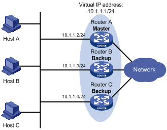
Assume that Router A is the master and therefore can forward packets to external networks, whereas Router B and Router C are backups and are thus in the state of listening. If Router A fails, Router B and Router C elect for a new master to forward packets to hosts on the LAN.
Load sharing
More than one VRRP group can be created on an interface of a router to allow the router to be the master of one VRRP group but a backup of another at the same time.
In load sharing mode, multiple routers provide services simultaneously. This mode requires two or more VRRP groups, each of which comprises a master and one or more backups. The masters of the VRRP groups are assumed by different routers, as shown in Figure 6.
Figure 6 VRRP in load sharing mode
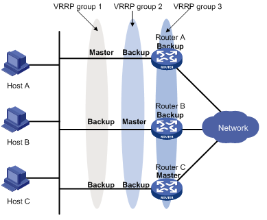
A router can be in multiple VRRP groups and hold a different priority in a different group.
As shown in Figure 6, the following VRRP groups are present:
· VRRP group 1—Router A is the master; Router B and Router C are the backups.
· VRRP group 2—Router B is the master; Router A and Router C are the backups.
· VRRP group 3—Router C is the master; Router A and Router B are the backups.
For load sharing among Router A, Router B, and Router C, hosts on the LAN need to be configured to use VRRP group 1, 2, and 3 as the default gateways respectively. When you configure VRRP priorities, make sure that each router holds such a priority in each VRRP group that it will take the expected role in the group.
VRRP load balancing mode
Overview
When VRRP works in standard protocol mode, only the master can forward packets and the backups are in the state of listening. You can create multiple VRRP groups to share the load among multiple routers, but hosts on the LAN need to be configured with different gateways, thus making the configuration complicated.
In load balancing mode, VRRP provides load balancing in addition to virtual gateway redundancy by mapping a virtual IP address to multiple virtual MAC addresses to assign each router in a VRRP group one virtual MAC address. In this way, each router in this VRRP group can respond to ARP requests (in an IPv4 network) or ND requests (in an IPv6 network) from corresponding hosts, so that different hosts can send packets to different routers, and each router in the VRRP group can forward packets. In load balancing mode, you need to create only one VRRP group to balance load among multiple routers, instead of allowing one router to bear the load but other routers to stay idle.
|
|
NOTE: VRRP load balancing mode is based on VRRP standard protocol mode, so mechanisms, such as master election, preemption, and tracking functions, in the standard protocol mode are also supported in the load balancing mode. In addition, VRRP load balancing mode has new mechanisms, which are introduced in the following sections. |
Assigning virtual MAC addresses
When VRRP works in load balancing mode, the master assigns virtual MAC addresses to the routers in the VRRP group and answers the ARP requests or ND requests from different hosts. The backup routers, however, do not answer the ARP requests or ND requests from the hosts.
Assume that a VRRP group works in an IPv4 network. The following describes how the load balancing mode works:
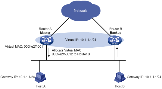
1. The master assigns virtual MAC addresses to the routers (including the master itself and the backups) in the VRRP group. For example, as shown in Figure 7, the virtual IP address of the VRRP group is 10.1.1.1/24; Router A is the master; Router B and Router C are the backups. Router A assigns 000f-e2ff-0011 to itself, and 000f-e2ff-0012 to Router B.
Figure 7 Allocating virtual MAC addresses
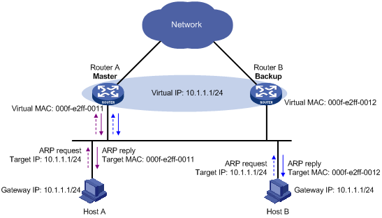
2. After receiving an ARP request destined for the virtual IP address of the VRRP group from a host, the master, based on the load balancing algorithm, uses a corresponding virtual MAC address to answer the ARP request. For example, as shown Figure 8, when Host A sends an ARP request to retrieve the MAC address of gateway 10.1.1.1, the master (Router A), after receiving the request, returns the virtual MAC address of Router A to Host A; when Host B sends an ARP request to retrieve the MAC address of gateway 10.1.1.1, the master (Router A), after receiving the request, returns the virtual MAC address of Router B to Host B.
Figure 8 Answering ARP requests
3. Different hosts send packets to different routers according to the requested virtual MAC addresses. For example, as shown in Figure 9, Host A regards the virtual MAC address of Router A as the gateway MAC address, so it sends packets to Router A for forwarding; Host B regards the virtual MAC address of Router B as the gateway MAC address, so it sends packets to Router B for forwarding.
Figure 9 Sending packets to different routers for forwarding
Virtual forwarder
Creating a virtual forwarder
Virtual MAC addresses help different hosts transmit packets to different routers in a VRRP group. To enable the routers in the VRRP group to forward the packets, be sure to create virtual forwarders (VFs) on the routers. Each VF associates with a virtual MAC address in the VRRP group and forwards packets destined to this virtual MAC address.
The following describes how VFs are created on the routers in a VRRP group:
1. The master assigns virtual MAC addresses to all routers in the VRRP group. After learning its virtual MAC address, a router in the VRRP group creates a VF that corresponds to this MAC address, and becomes the owner of this VF.
2. The router advertises the VF information to the other routers in the VRRP group.
3. After receiving the VF advertisement, each of the other routers creates the advertised VF.
As described in the preceding steps, each router in the VRRP group creates not only a VF corresponding to its virtual MAC address, but also VFs advertised by the other routes in the VRRP group..
VF weight and priority
The weight of a VF indicates the forwarding capability of a router. A higher weight indicates a higher forwarding capability. When the weight is lower than the lower limit of failure, the router cannot be capable of forwarding packets for the hosts.
The priority of a VF determines the VF state. Among the VFs that correspond to the same virtual MAC address on different routers in the VRRP group, a VF with the highest priority is in the active state and is known as the active virtual forwarder (AVF), which forwards packets; other VFs are in the listening state and are known as the listening virtual forwarders (LVFs), which listen to the state of the AVF. The priority value of a VF ranges from 0 to 255, where 255 is reserved for the VF owner. If the weight of a VF owner is higher than or equal to the lower limit of failure—the lower limit is 10, the priority value of the VF owner is 255.
The priority value of a VF is calculated based on its weight:
· If the weight of a VF is higher than or equal to the lower limit of failure, and the router where the VF resides is the owner of the VF, the priority value of the VF is 255.
· If the weight of a VF is higher than or equal to the lower limit of failure, but the router where the VF resides is not the owner of the VF, the priority value of the VF is weight/(number of local AVFs +1)
· If the weight of a VF is lower than the lower limit of failure, the priority value of the VF is 0.
VF backup
The VFs corresponding to a virtual MAC address on different routers in the VRRP group back up one another.
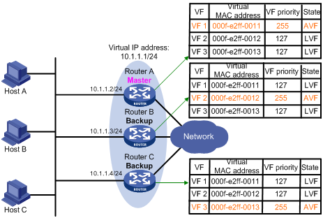
Figure 10 illustrates the VF information on each router in the VRRP group and how the routers back up one another. The master, Router A, assigns virtual MAC addresses 000f-e2ff-0011, 000f-e2ff-0012, and 000f-e2ff-0013 to itself, Router B, and Router C respectively. The VFs corresponding to these three virtual MAC addresses, VF 1, VF 2, and VF 3, are created on each of the three routers, and the VFs corresponding to the same virtual MAC address on different routers back up one another. For example, VF 1 on Router A, Router B, and Router C can implement backup.
· Router A is the owner of VF 1, and the priority value of VF 1 on Router A is 255. In this case, VF 1 on Router A acts as the AVF to forward the packets destined for virtual MAC address 000f-e2ff-0011.
· The priority value of VF 1 on Router B and Router C is weight/(number of local AVFs + 1), that is, 255/(1 + 1) =127, which is lower than that of VF 1 on Router A. In this case, VF 1 on both Router B and Router C acts as the LVF to listen to the status of VF 1 on Router A.
· When VF 1 on Router A fails, VF 1 on Router B and Router C elects the one with a higher priority value as the new AVF, responsible for forwarding the packets destined for virtual MAC address 000f-e2ff-0011.
|
|
NOTE: A VF always works in preemptive mode. When an LVF finds its priority value higher than that in the advertisement sent by the AVF, the LVF declares itself as the AVF. |
VF timers
When the AVF on a router fails, the newly elected AVF on another router creates a redirect timer and a timeout timer for the failed AVF:
· Redirect Timer—Before this timer times out, the master still uses the virtual MAC address corresponding to the failed AVF to respond to ARP/ND requests from the hosts, and the VF owner can share traffic load if the VF owner resumes normal operation within this time. When this timer times out, the master stops using the virtual MAC address corresponding to the failed AVF to respond to ARP/ND requests from the hosts.
· Timeout Timer—The duration that the new AVF takes over the VF owner. Before this timer times out, all the routers in the VRRP group keep the failed AVF, and the new AVF forwards the packets destined for the virtual MAC address corresponding to the failed AVF. When this timer times out, all the routers in the VRRP group remove the failed AVF, and the new AVF stops forwarding the packets destined for the virtual MAC address corresponding to the failed AVF.
VF tracking
The AVF forwards packets destined to the MAC address of the AVF. If the uplink of the AVF fails and no LVF is notified to take over the AVF's work, hosts (on the LAN) that use the MAC address of the AVF as their gateway MAC address cannot access the external network.
This problem can be solved by the VF tracking function. You can monitor the uplink state by using network quality analyzer (NQA) and bidirectional forwarding detection (BFD), and establish the collaboration between the VF and the NQA or between the VF and the BFD through the tracking function. When the uplink fails, the state of the monitored track entry changes to negative and the weight of the VF decreases by a specified value. Then, the VF with a higher priority becomes the AVF and forwards packets.
Packet types
VRRP standard protocol mode defines only VRRP advertisement. Only the master in a VRRP group periodically sends VRRP advertisements, and the backups do not send VRRP advertisements.
VRRP load balancing mode defines the following types of packets:
· Advertisement—VRRP advertises VRRP group state and information about the VF that is in the active state. Both the master and the backups periodically send VRRP advertisements.
· Request—If a backup is not the VF owner, it sends a request to ask the master to assign a virtual MAC address.
· Reply—When receiving a request, the master sends a reply to the backup router to assign a virtual MAC address. After receiving the reply, the backup router creates a VF that corresponds to the virtual MAC address, and then becomes the owner of this VF.
· Release—When a VF owner fails, the router that takes over its responsibility sends a release after a specified period of time to notify the other routers in the VRRP group to delete the VF of the failed VF owner.
|
|
NOTE: The format of these packets is similar to that of the advertisement in VRRP standard protocol mode except that a packet used in load balancing mode is appended with option field, which contains information for load balancing. |
Configuring VRRP for IPv4
VRRP for IPv4 configuration task list
To form a VRRP group, perform the following configurations on each device in the VRRP group.
Complete these tasks to configure VRRP for IPv4:
|
Task |
Remarks |
|
Optional |
|
|
Specifying the type of MAC addresses mapped to virtual IP addresses |
Optional When VRRP works in load balancing mode, this configuration is not effective. |
|
Optional |
|
|
Required |
|
|
Configuring router priority, preemptive mode and tracking function |
Optional |
|
Optional The VF tracking function is effective only when VRRP works in load balancing mode. |
|
|
Optional |
|
|
Optional |
Configuring a VRRP working mode
VRRP can work in either of the following modes:
· Standard protocol mode—When VRRP works in this mode, only the master in a VRRP group is responsible for forwarding packets.
· Load balancing mode—When VRRP works in this mode, all the routers (master and backups) that have the AVF in a VRRP group can forward packets, thus implementing load balancing.
After the VRRP working mode is specified on a router, all VRRP groups on the router work in the specified working mode.
To configure a VRRP working mode:
|
Step |
Command |
Remarks |
|
|
1. Enter system view. |
system-view |
N/A |
|
|
2. Configure a VRRP working mode. |
·
Configure VRRP to work in standard protocol
mode: ·
Configure VRRP to work in load balancing mode: |
Use either command. By default, VRRP works in standard protocol mode. |
|
Specifying the type of MAC addresses mapped to virtual IP addresses
After you specify the type of MAC addresses mapped to the virtual IP addresses of VRRP groups and create a VRRP group, the master in the VRRP group uses the specified type of MAC address as the source MAC address for sending packets and uses the specified type of MAC address to answer ARP requests from hosts so that the hosts in the internal network can learn the mapping between the IP address and the MAC address.
The following types of MAC addresses are available to be mapped to the virtual IP address of a VRRP group:
· Virtual MAC address—By default, a virtual MAC address is automatically created for a VRRP group when the VRRP group is created, and the virtual IP address of the VRRP group is mapped to the virtual MAC address. When such a mapping is adopted, the hosts in the internal network do not need to update the mapping between the IP address and MAC address when the master changes.
· Real MAC address of an interface—In case that an IP address owner exists in a VRRP group, if the virtual IP address is mapped to the virtual MAC address, two MAC addresses are mapped to one IP address. To avoid such as problem, map the virtual IP address of the VRRP group to the real MAC address of an interface to forward the packets from a host to the IP address owner.
To specify the type of MAC addresses mapped to virtual IP addresses:
|
Step |
Command |
Remarks |
|
1. Enter system view. |
system-view |
N/A |
|
2. Specify the type of MAC addresses mapped to virtual IP addresses. |
vrrp method { real-mac | virtual-mac } |
Optional Virtual MAC address by default |
|
|
NOTE: · When VRRP works in load balancing mode, a virtual IP address is always mapped to a virtual MAC address regardless of which type of MAC addresses are specified to be mapped to virtual IP addresses. · Specify the type of the MAC addresses to be mapped to the virtual IP addresses before creating a VRRP group. Otherwise, you cannot change the type of the MAC addresses mapped to virtual IP addresses. · If VRRP groups with the same ID are created on multiple interfaces of a device, and the VRRP advertisements of these VRRP groups are to be sent through QinQ networks, H3C recommends you to map the real MAC addresses of the interfaces to the virtual IP addresses of these VRRP groups. Otherwise, the VRRP advertisements of these VRRP groups cannot be sent successfully. |
Specifying the VRRP control VLAN
With VLAN termination, after a port receiving a VLAN packet, it removes its VLAN tag(s) and then forwards it at Layer 3 or processes it in other ways. VLAN termination falls in the following categories:
· Unambiguous termination—Terminates VLAN packets from a specified VLAN only. In other words, after receiving a packet from the specific VLAN, a port configured with unambiguous VLAN termination removes its VLAN tag.
· Ambiguous termination—Terminates VLAN packets from multiple VLANs whose VLAN IDs are in the specified range. In other words, after receiving a packet from a VLAN in the specified range, a port configured with ambiguous VLAN termination removes its VLAN tag.
By default, an ambiguous termination-enabled Layer 3 subinterface or VLAN interface drops broadcast and multicast packets they receive, instead of transmitting them.
You can enable a Layer 3 Ethernet subinterface, or a VLAN interface configured with ambiguous termination to transmit broadcast/multicast packets within all VLANs whose VLAN packets are configured to be terminated by the subinterface or VLAN interface.
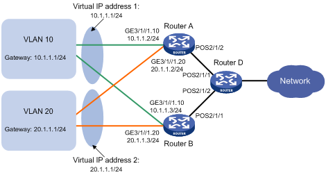
As shown in Figure 11, configure ambiguous VLAN termination for VLAN 10 and VLAN 20 on the Layer 3 Ethernet subinterfaces on routers. To make sure that the master can periodically multicast VRRP advertisements to the backups, be sure to enable the subinterfaces configured with VLAN termination to transmit broadcast/multicast packets. Then, the master sends VRRP advertisements within all VLANs whose VLAN packets are configured to be terminated by the subinterfaces. If the Layer 3 Ethernet subinterfaces are configured to terminate packets from many VLANs, there will be many VRRP advertisements to be transmitted through the subinterfaces, and the performance of the router will be seriously affected.
To solve this problem, you can configure a VRRP control VLAN to allow the master to send VRRP advertisements only within the control VLAN when the subinterfaces configured with VLAN termination are disabled from transmitting broadcast or multicast packets.
VRRP control VLAN falls into the following categories:
· Specifying a single VLAN tag—For subinterfaces configured with ambiguous Dot1q termination, this type of control VLAN should be specified.
· Specifying both inner and outer VLAN tags—For subinterfaces configured with ambiguous QinQ termination, this type of control VLAN should be specified.
|
|
NOTE: · You need to specify a control VLAN for only Layer 3 Ethernet subinterfaces and Layer 3 aggregate subinterfaces that have been configured with ambiguous VLAN termination. · When VRRP works in load balancing mode, you cannot specify the VRRP control VLAN. · If you specified the VRRP control VLAN, to update MAC address entries on devices in the VLAN terminated ambiguously after an active/standby switchover, use the arp send-gratuitous-arp command to enable the routers in the VRRP group to periodically send gratuitous ARP packets. For more information about the arp send-gratuitous-arp command, see Gratuitous ARP configuration commands in the Layer 3—IP Services Command Reference. · For more information about VLAN termination, see Layer 2—LAN Switching Configuration Guide. |
To specify the VRRP control VLAN:
|
Step |
Command |
Remarks |
|
|
1. Enter system view. |
system-view |
N/A |
|
|
2. Enter interface view. |
· Enter Layer 3 Ethernet subinterface view: · Enter Layer 3 aggregation subinterface
view: |
Use either command. |
|
|
3. Specify a VRRP control VLAN. |
· Specify a VRRP control VLAN for the subinterface
configured with ambiguous Dot1q termination: · Specify a VRRP control VLAN for the subinterface
configured with ambiguous QinQ termination: |
Use either command. By default, no VRRP control VLAN is specified for the subinterface configured with VLAN termination. That is, the master sends VRRP advertisements within all VLANs whose VLAN packets are configured to be terminated by the subinterface. |
|
Creating a VRRP group and configuring virtual IP address
When creating a VRRP group on an interface, configure a virtual IP address for the VRRP group. If the interface connects to multiple sub-networks, you can configure multiple virtual IP addresses for the VRRP group to realize router backup on different sub-networks.
A VRRP group is automatically created when you specify the first virtual IP address for the VRRP group. If you specify another virtual IP address for the VRRP group later, the virtual IP address is added to the virtual IP address list of the VRRP group.
Configuration prerequisites
Before creating a VRRP group and configuring a virtual IP address on an interface, configure an IP address for the interface and make sure that it is in the same network segment as the virtual IP address to be configured.
Configuration procedure
To create a VRRP group and configure a virtual IP address:
|
Step |
Command |
Remarks |
|
1. Enter system view. |
system-view |
N/A |
|
2. Enter the specified interface view. |
interface interface-type interface-number |
N/A |
|
3. Create a VRRP group and configure a virtual IP address for the VRRP group. |
vrrp vrid virtual-router-id virtual-ip virtual-address |
VRRP group is not created by default. |
|
|
NOTE: · When VRRP works in standard protocol mode, the virtual IP address of a VRRP group can be either an unused IP address on the segment where the VRRP group resides or the IP address of an interface on a router in the VRRP group. In the latter case, the router is called the IP address owner. · When a router is the IP address owner in a VRRP group, H3C recommends you not to use the IP address of the interface (virtual IP address of the VRRP group) to establish a neighbor relationship with the adjacent router, that is, not to use the network command to enable OSPF on the interface. For more information about network command, see Layer 3—IP Routing Command Reference. · When VRRP works in load balancing mode, the virtual IP address of a VRRP group cannot be the same as the IP address of any interface in the VRRP group. In other words, in load balancing mode, the VRRP group does not have an IP address owner. · A VRRP group is removed after you remove all the virtual IP addresses configured for it. In addition, configurations on that VRRP group do not take effect any longer. · Removal of the VRRP group on the IP address owner causes IP address collision. To solve the collision, modify the IP address of the interface on the IP address owner first and then remove the VRRP group from the interface. · The virtual IP address of a VRRP group cannot be 0.0.0.0, 255.255.255.255, loopback addresses, non class A/B/C addresses or other illegal IP addresses such as 0.0.0.1. · A VRRP group operates normally only when the configured virtual IP address and the interface IP address belong to the same segment and are legal host addresses. If the configured virtual IP address and the interface IP address do not belong to the same network segment, or the configured IP address is the network address or network broadcast address of the network segment to which the interface IP address belongs, the state of the VRRP group is always initialize though you can perform the configuration successfully. In this case, VRRP does not take effect. |
Configuring router priority, preemptive mode and tracking function
Configuration prerequisites
Before you configure router priority, preemptive mode and tracking function, create a VRRP group on an interface and configure a virtual IP address for it.
Configuration procedure
By configuring router priority, preemptive mode, interface tracking, or a track entry, you can determine which router in the VRRP group serves as the master.
To configure router priority, preemptive mode and the tracking function:
|
Step |
Command |
Remarks |
|
1. Enter system view. |
system-view |
N/A |
|
2. Enter interface view. |
interface interface-type interface-number |
N/A |
|
3. Configure router priority in the VRRP group. |
vrrp vrid virtual-router-id priority priority-value |
Optional. 100 by default. |
|
4. Configure the router in the VRRP group to work in preemptive mode and configure preemption delay. |
vrrp vrid virtual-router-id preempt-mode [ timer delay delay-value ] |
Optional. The router in the VRRP group works in preemptive mode and the preemption delay is 0 seconds by default. |
|
5. Configure the interface to be tracked. |
vrrp vrid virtual-router-id track interface interface-type interface-number [ reduced priority-reduced ] |
Optional. No interface is being tracked by default. |
|
6. Configure VRRP to track a specified track entry. |
vrrp vrid virtual-router-id track track-entry-number [ reduced priority-reduced | switchover ] |
Optional. Not configured by default. |
|
|
NOTE: · The running priority of an IP address owner is always 255 and you do not need to configure it. An IP address owner always works in preemptive mode. · If you configure an interface to be tracked or a track entry to be monitored on a router that is the IP address owner in a VRRP group, the configuration does not take effect. If the router is not the IP address owner in the VRRP group later, the configuration takes effect. · Do not configure VRRP tracking for an interface or a track entry on an IP address owner. · The tracked interface can be a Layer 3 Ethernet interface, a VLAN interface, a Layer 3 aggregate interface, a POS interface, an MP-group interface, an HDLC link bundle interface, or an RPR logical interface. · If the state of a tracked interface changes from down or removed to up, the priority of the router where the interface resides is automatically restored. · If the state of a track entry changes from negative or invalid to positive, the priority of the router where the track entry is configured is automatically restored. |
Configuring VF tracking
Configuration prerequisites
Before you configure the VF tracking function, create a VRRP group and configure a virtual IP address for it.
Configuration procedure
VRRP works in load balancing mode. Suppose that the VF is configured to monitor the track entry. When the state of the track entry becomes negative, the weight values of all VFs on the routers decrease by a specified value; when the state of the track entry becomes positive or invalid, the weight values of all VFs on the routers restore their original values.
To configure VF tracking:
|
Step |
Command |
Remarks |
|
1. Enter system view. |
system-view |
N/A |
|
2. Enter the specified interface view. |
interface interface-type interface-number |
N/A |
|
3. Configure the VF to monitor a specified track entry and specify the amount by which the weight decreases. |
vrrp vrid virtual-router-id weight track track-entry-number [ reduced weight-reduced ] |
No track entry is specified by default. |
|
|
NOTE: · You can configure the VF tracking function when VRRP works in either standard protocol mode or load balancing mode; however, the VF tracking function is effective only when VRRP works in load balancing mode. · By default, the weight of a VF is 255, and its lower limit of failure is 10. · If the weight of a VF owner is higher than or equal to the lower limit of failure, the priority of the VF owner is always 255 and does not change with the weight value. Therefore, in case of an uplink failure, another VF takes over the VF owner's work and becomes the AVF only when the weight of the VF owner decreases by a properly specified value and becomes lower than the lower limit of failure. In other words, the weight of the VF owner decreases by more than 245. |
Configuring VRRP packet attributes
Configuration prerequisites
Before you configure the relevant attributes of VRRP packets, create a VRRP group and configure a virtual IP address for it.
Configuration procedure
To configure VRRP packet attributes:
|
Step |
Command |
Remarks |
|
1. Enter system view. |
system-view |
N/A |
|
2. Enter the specified interface view. |
interface interface-type interface-number |
N/A |
|
3. Configure the authentication mode and authentication key when the VRRP groups send and receive VRRP packets. |
vrrp vrid virtual-router-id authentication-mode { md5 | simple } key |
Optional. Authentication is not performed by default. |
|
4. Configure the time interval for the master in the VRRP group to send VRRP advertisements. |
vrrp vrid virtual-router-id timer advertise adver-interval |
Optional. 1 second by default. |
|
5. Disable TTL check on VRRP packets. |
vrrp un-check ttl |
Optional. Enabled by default. You do not need to create a VRRP group before executing this command. |
|
|
NOTE: · You might configure different authentication modes and authentication keys for the VRRP groups on an interface. However, the members of the same VRRP group must use the same authentication mode and authentication key. · Excessive traffic might cause a backup to trigger a change of its status because the backup does not receive any VRRP advertisements for a specified period of time. To solve this problem, prolong the time interval to send VRRP advertisements. · Configuring different intervals for sending VRRP advertisements on the routers in a VRRP group might cause a backup to trigger a change of its status because the backup does not receive any VRRP advertisements for a specified period of time. To solve this problem, configure the same interval for sending VRRP advertisements on each router in the VRRP group. |
Enabling the trap function for VRRP
When the trap function is enabled for VRRP, VRRP generates traps with severity level errors to report its key events. The traps are sent to the information center of the device, where you can configure whether to output the trap information and the output destination. For how to configure the information center, see Network Management and Monitoring Configuration Guide.
To enable the trap function for VRRP:
|
Step |
Command |
Remarks |
|
1. Enter system view. |
system-view |
N/A |
|
2. Enable the trap function for VRRP. |
snmp-agent trap enable vrrp [ authfailure | newmaster ] |
Optional Enabled by default |
|
|
NOTE: For more information about the snmp-agent trap enable vrrp command, see the snmp-agent trap enable command in Network Management and Monitoring Command Reference. |
Displaying and maintaining VRRP for IPv4
|
Task |
Command |
Remarks |
|
Display VRRP group status. |
display vrrp [ verbose ] [ interface interface-type interface-number [ vrid virtual-router-id ] ] [ | { begin | exclude | include } regular-expression ] |
Available in any view |
|
Display VRRP group statistics. |
display vrrp statistics [ interface interface-type interface-number [ vrid virtual-router-id ] ] [ | { begin | exclude | include } regular-expression ] |
Available in any view |
|
Clear VRRP group statistics. |
reset vrrp statistics [ interface interface-type interface-number [ vrid virtual-router-id ] ] |
Available in user view |
Configuring VRRP for IPv6
VRRP for IPv6 configuration task list
Complete these tasks to configure VRRP for IPv6:
|
Task |
Remarks |
|
Optional |
|
|
Specifying the type of MAC addresses mapped to virtual IPv6 addresses |
Optional When VRRP works in load balancing mode, this configuration is not effective. |
|
Creating a VRRP group and configuring a virtual IPv6 address |
Required |
|
Configuring router priority, preemptive mode and tracking function |
Optional |
|
Optional The VF tracking function is effective only when VRRP works in load balancing mode. |
|
|
Optional |
Specifying the type of MAC addresses mapped to virtual IPv6 addresses
After you specify the type of MAC addresses mapped to the virtual IPv6 address of VRRP groups and create a VRRP group, the master in the VRRP group uses the specified type of MAC address as the source MAC address for sending packets and uses the specified type of MAC address to answer ND requests from hosts so that the hosts in the internal network can learn the mapping between the IPv6 address and the MAC address.
The following types of MAC addresses are available to be mapped to the virtual IPv6 address of a VRRP group:
· Virtual MAC address—By default, a virtual MAC address is automatically created for a VRRP group when the VRRP group is created, and the virtual IPv6 address of the VRRP group is mapped to the virtual MAC address. When such a mapping is adopted, the hosts in the internal network do not need to update the mapping between the IPv6 address and the MAC address when the master changes.
· Real MAC address of an interface—In case that an IP address owner exists in a VRRP group, if the virtual IPv6 address is mapped to the virtual MAC address, two MAC addresses are mapped to one IPv6 address. To avoid such as problem, map the virtual IPv6 address of the VRRP group to the real MAC address of an interface to forward the packets from a host to the IP address owner.
To specify the type of MAC addresses mapped to virtual IPv6 addresses:
|
Step |
Command |
Remarks |
|
1. Enter system view. |
system-view |
N/A |
|
2. specify the type of MAC addresses mapped to virtual IPv6 addresses. |
vrrp ipv6 method { real-mac | virtual-mac } |
Optional Virtual MAC address by default |
|
|
NOTE: · When VRRP works in load balancing mode, a virtual IPv6 address is always mapped to a virtual MAC address regardless of which type of MAC addresses are specified to be mapped to virtual IPv6 addresses. · Specify the type of the MAC addresses to be mapped to the virtual IPv6 addresses before creating a VRRP group. Otherwise, you cannot change the type of the MAC addresses mapped to virtual IPv6 addresses. |
Creating a VRRP group and configuring a virtual IPv6 address
When creating a VRRP group, configure a virtual IPv6 address for the VRRP group. You can configure multiple virtual IPv6 addresses for a VRRP group.
A VRRP group is automatically created when you specify the first virtual IPv6 address for the VRRP group. If you specify another virtual IPv6 address for the VRRP group later, the virtual IPv6 address is added to the virtual IPv6 address list of the VRRP group.
Configuration prerequisites
Before creating a VRRP group and configuring a virtual IPv6 address on an interface, configure an IPv6 address for the interface and make sure that it is in the same network segment as the virtual IPv6 address to be configured.
Configuration procedure
To create a VRRP group and configure its virtual IPv6 address:
|
Step |
Command |
Remarks |
|
1. Enter system view. |
system-view |
N/A |
|
2. Enter the specified interface view. |
interface interface-type interface-number |
N/A |
|
3. Create a VRRP group and configure its virtual IPv6 address, which is a link local address. |
vrrp ipv6 vrid virtual-router-id virtual-ip virtual-address link-local |
No VRRP group is created by default. The first virtual IPv6 address of the VRRP group must be a link local address. Only one link local address is allowed in a VRRP group, and must be removed the last. |
|
4. Configure the VRRP group with a virtual IPv6 address, which is a global unicast address. |
vrrp ipv6 vrid virtual-router-id virtual-ip virtual-address |
Optional. By default, no global unicast address is configured as the virtual IPv6 address of a VRRP group. |
|
|
NOTE: · When a router is the IP address owner in a VRRP group, H3C recommends you not to use the IPv6 address of the interface (virtual IPv6 address of the VRRP group) to establish an OSPFv3 neighbor relationship with the adjacent router, that is, not to use the ospfv3 area command to enable OSPFv3 on the interface. For more information about ospfv3 area command, see Layer 3—IP Routing Command Reference. · When VRRP works in load balancing mode, the virtual IPv6 address of a VRRP group cannot be the same as the IPv6 address of any interface in the VRRP group. In other words, a VRRP group does not have an IP address owner in load balancing mode. · A VRRP group is removed after you remove all the virtual IPv6 addresses in it. In addition, configurations on that VRRP group do not take effect any longer. · Removal of the VRRP group on the IP address owner causes IP address collision. To resolve the collision, change the IPv6 address of the interface on the IP address owner first and then remove the VRRP group from the interface. |
Configuring router priority, preemptive mode and tracking function
Configuration prerequisites
Before you configure router priority, preemptive mode and tracking function, create a VRRP group and configure its virtual IPv6 address.
Configuration procedure
By configuring router priority, preemptive mode, interface tracking, or a track entry, determine which router in the VRRP group serves as the master.
To configure router priority, preemptive mode and interface tracking:
|
Step |
Command |
Remarks |
|
1. Enter system view. |
system-view |
N/A |
|
2. Enter the specified interface view. |
interface interface-type interface-number |
N/A |
|
3. Configure the priority of the router in the VRRP group. |
vrrp ipv6 vrid virtual-router-id priority priority-value |
Optional. 100 by default. |
|
4. Configure the router in the VRRP group to work in preemptive mode and configure preemption delay of the VRRP group. |
vrrp ipv6 vrid virtual-router-id preempt-mode [ timer delay delay-value ] |
Optional. The router in the VRRP group works in preemptive mode and the preemption delay is zero seconds by default. |
|
5. Configure the interface to be tracked. |
vrrp ipv6 vrid virtual-router-id track interface interface-type interface-number [ reduced priority-reduced ] |
Optional. No interface is being tracked by default. |
|
6. Configure VRRP to track a specified track entry. |
vrrp ipv6 vrid virtual-router-id track track-entry-number [ reduced priority-reduced | switchover ] |
Optional. Not configured by default. |
|
|
NOTE: · The running priority of an IP address owner is always 255 and you do not need to configure it. An IP address owner always works in preemptive mode. · Interface tracking is not configurable on an IP address owner. · If you configure an interface to be tracked or a track entry to be monitored on a router that is the IP address owner in a VRRP group, the configuration does not take effect. If the router is not the IP address owner in the VRRP group later, the configuration takes effect. · The tracked interface can be a Layer 3 Ethernet interface, a VLAN interfaces, a Layer 3 aggregate interface, a POS interface, an MP-group interface, an HDLC link bundle interface, or an RPR logical interfaces. · If the state of a tracked interface changes from down or removed to up, the priority of the router that owns the interface is automatically restored. · If the state of a track entry changes from negative or invalid to positive, the priority of the router where the track entry is configured is automatically restored. |
Configuring VF tracking
Configuration prerequisites
Before you configure the VF tracking function, create a VRRP group and configure a virtual IPv6 address for it.
Configuration procedure
VRRP works in load balancing mode. Suppose that the VF is configured to monitor a track entry. When the state of the track entry becomes negative or invalid, the weight values of all VFs on the routers decrease by a specified value; when the state of the track entry becomes positive, the weight values of all VFs on the routers restore their original values.
To configure VF tracking:
|
Step |
Command |
Remarks |
|
1. Enter system view. |
system-view |
N/A |
|
2. Enter the specified interface view. |
interface interface-type interface-number |
N/A |
|
3. Configure the VF to monitor a specified track entry and specify the amount by which the weight decreases. |
vrrp ipv6 vrid virtual-router-id weight track track-entry-number [ reduced weight-reduced ] |
No track entry is specified by default. |
|
|
NOTE: · You can configure the VF tracking function when VRRP works in either standard protocol mode or load balancing mode; however, the VF tracking function is effective only when VRRP works in load balancing mode. · By default, the weight of a VF is 255, and its lower limit of failure is 10. · If the weight of a VF owner is higher than or equal to the lower limit of failure, the priority of the VF owner is always 255 and does not change with the weight value. Therefore, if an uplink fails, another VF takes over the VF owner's work and becomes the AVF only when the weight of the VF owner decreases by a properly specified value and becomes lower than the lower limit of failure. In other words, the weight of the VF owner decreases by more than 245. |
Configuring VRRP packet attributes
Configuration prerequisites
Before you configure the relevant attributes of VRRP packets, create a VRRP group and configure a virtual IPv6 address.
Configuration procedure
To configure VRRP packet attributes:
|
Step |
Command |
Remarks |
|
1. Enter system view. |
system-view |
N/A |
|
2. Enter the specified interface view. |
interface interface-type interface-number |
N/A |
|
3. Configure the authentication mode and authentication key when the VRRP groups send or receive VRRP packets. |
vrrp ipv6 vrid virtual-router-id authentication-mode simple key |
Optional. Authentication is not performed by default. |
|
4. Configure the time interval for the master in the VRRP group to send VRRP advertisement. |
vrrp ipv6 vrid virtual-router-id timer advertise adver-interval |
Optional. 100 centiseconds by default. |
Displaying and maintaining VRRP for IPv6
|
Task |
Command |
Remarks |
|
Display VRRP group status. |
display vrrp ipv6 [ verbose ] [ interface interface-type interface-number [ vrid virtual-router-id ] ] [ | { begin | exclude | include } regular-expression ] |
Available in any view |
|
Display VRRP group statistics. |
display vrrp ipv6 statistics [ interface interface-type interface-number [ vrid virtual-router-id ] ] [ | { begin | exclude | include } regular-expression ] |
Available in any view |
|
Clear VRRP group statistics. |
reset vrrp ipv6 statistics [ interface interface-type interface-number [ vrid virtual-router-id ] ] |
Available in user view |
IPv4-based VRRP configuration examples
This section provides these configuration examples:
· Single VRRP group configuration example
· VRRP interface tracking configuration example
· Multiple VRRP groups configuration example
· VRRP load balancing mode configuration example
Single VRRP group configuration example
Network requirements
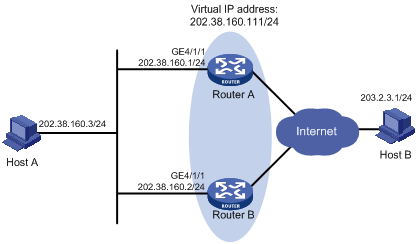
· Host A needs to access Host B on the Internet, using 202.38.160.111/24 as its default gateway.
· Router A and Router B belong to VRRP group 1 with the virtual IP address of 202.38.160.111/24.
· If Router A operates normally, packets sent from Host A to Host B are forwarded by Router A. If Router A fails, packets sent from Host A to Host B are forwarded by Router B.
Configuration procedure
1. Configure Router A:
<RouterA> system-view
[RouterA] interface GigabitEthernet 4/1/1
[RouterA-GigabitEthernet4/1/1] ip address 202.38.160.1 255.255.255.0
# Create VRRP group 1 and configure its virtual IP address as 202.38.160.111.
[RouterA-GigabitEthernet4/1/1] vrrp vrid 1 virtual-ip 202.38.160.111
# Configure the priority of Router A in the VRRP group 1 as 110, which is higher than that of Router B (100), so that Router A can become the master.
[RouterA-GigabitEthernet4/1/1] vrrp vrid 1 priority 110
# Configure Router A to work in preemptive mode so that it can become the master whenever it works normally. Configure the preemption delay as five seconds to avoid frequent status switchover.
[RouterA-GigabitEthernet4/1/1] vrrp vrid 1 preempt-mode timer delay 5
2. Configure Router B:
<RouterB> system-view
[RouterB] interface GigabitEthernet 4/1/1
[RouterB-GigabitEthernet4/1/1] ip address 202.38.160.2 255.255.255.0
# Create VRRP group 1 and configure its virtual IP address as 202.38.160.111.
[RouterB-GigabitEthernet4/1/1] vrrp vrid 1 virtual-ip 202.38.160.111
# Configure Router B to work in the preemptive mode, with the preemption delay set to 5 seconds.
[RouterB-GigabitEthernet4/1/1] vrrp vrid 1 preempt-mode timer delay 5
3. Verify the configuration:
After the configuration, Host B can be pinged successfully on Host A. To verify your configuration, use the display vrrp verbose command.
# Display the detailed information of VRRP group 1 on Router A.
[RouterA-GigabitEthernet4/1/1] display vrrp verbose
IPv4 Standby Information:
Run Mode : Standard
Run Method : Virtual MAC
Total number of virtual routers : 1
Interface GigabitEthernet4/1/1
VRID : 1 Adver Timer : 1
Admin Status : Up State : Master
Config Pri : 110 Running Pri : 110
Preempt Mode : Yes Delay Time : 5
Auth Type : None
Virtual IP : 202.38.160.111
Virtual MAC : 0000-5e00-0101
Master IP : 202.38.160.1
# Display the detailed information of VRRP group 1 on Router B.
[RouterB-GigabitEthernet4/1/1] display vrrp verbose
IPv4 Standby Information:
Run Mode : Standard
Run Method : Virtual MAC
Total number of virtual routers : 1
Interface GigabitEthernet4/1/1
VRID : 1 Adver Timer : 1
Admin Status : Up State : Backup
Config Pri : 100 Running Pri : 100
Preempt Mode : Yes Delay Time : 5
Auth Type : None
Virtual IP : 202.38.160.111
Master IP : 202.38.160.1
The output shows that in VRRP group 1 Router A is the master, Router B is the backup and packets sent from Host A to Host B are forwarded by Router A.
If Router A fails, you can still ping Host B successfully on Host A. To view the detailed information of the VRRP group on Router B, use the display vrrp verbose command.
# If Router A fails, display the detailed information of VRRP group 1 on Router B.
[RouterB-GigabitEthernet4/1/1] display vrrp verbose
IPv4 Standby Information:
Run Mode : Standard
Run Method : Virtual MAC
Total number of virtual routers : 1
Interface GigabitEthernet4/1/1
VRID : 1 Adver Timer : 1
Admin Status : Up State : Master
Config Pri : 100 Running Pri : 100
Preempt Mode : Yes Delay Time : 5
Auth Type : None
Virtual IP : 202.38.160.111
Virtual MAC : 0000-5e00-0101
Master IP : 202.38.160.2
The output shows that if Router A fails, Router B becomes the master, and packets sent from host A to host B are forwarded by Router B.
# After Router A resumes normal operation, use the display vrrp verbose command to display the detailed information of VRRP group 1 on Router A.
[RouterA-GigabitEthernet4/1/1] display vrrp verbose
IPv4 Standby Information:
Run Mode : Standard
Run Method : Virtual MAC
Total number of virtual routers : 1
Interface GigabitEthernet4/1/1
VRID : 1 Adver Timer : 1
Admin Status : Up State : Master
Config Pri : 110 Running Pri : 110
Preempt Mode : Yes Delay Time : 5
Auth Type : None
Virtual IP : 202.38.160.111
Virtual MAC : 0000-5e00-0101
Master IP : 202.38.160.1
The output shows that after Router A resumes normal operation, it becomes the master, and packets sent from Host A to Host B are forwarded by Router A.
VRRP interface tracking configuration example
Network requirements
· Host A wants to access Host B on the Internet, using 202.38.160.111/24 as its default gateway.
· Router A and Router B belong to VRRP group 1 with the virtual IP address of 202.38.160.111/24.
· When Router A operates normally, packets sent from Host A to Host B are forwarded by Router A; when interface GigabitEthernet 4/1/2 through which Router A connects to the internet is not available, packets sent from Host A to Host B are forwarded by Router B.
· To prevent attacks to the VRRP group from illegal users by using spoofed packets, configure the authentication mode as plain text to authenticate the VRRP packets in VRRP group 1, and specify the authentication key as hello.
Figure 13 Network diagram
Configuration procedure
1. Configure Router A:
<RouterA> system-view
[RouterA] interface GigabitEthernet 4/1/1
[RouterA-GigabitEthernet4/1/1] ip address 202.38.160.1 255.255.255.0
# Create VRRP group 1 and configure its virtual IP address as 202.38.160.111.
[RouterA-GigabitEthernet4/1/1] vrrp vrid 1 virtual-ip 202.38.160.111
# Configure the priority of Router A in the VRRP group as 110, which is higher than that of Router B (100), so that Router A can become the master.
[RouterA-GigabitEthernet4/1/1] vrrp vrid 1 priority 110
# Configure the authentication mode of the VRRP group as simple and authentication key as hello.
[RouterA-GigabitEthernet4/1/1] vrrp vrid 1 authentication-mode simple hello
# Configure the master to send VRRP packets every five seconds.
[RouterA-GigabitEthernet4/1/1] vrrp vrid 1 timer advertise 5
# Configure Router A to work in preemptive mode, so that it can become the master whenever it works normally. Configure the preemption delay as five seconds to avoid frequent status switchover.
[RouterA-GigabitEthernet4/1/1] vrrp vrid 1 preempt-mode timer delay 5
# Set interface GigabitEthernet 4/1/2 on Router A to be tracked, and configure the amount by which the priority value decreases to be more than 10 (30 in this example), so that when GigabitEthernet 4/1/2 fails, the priority of Router A in VRRP group 1 decreases to a value lower than 100 and thus Router B can become the master.
[RouterA-GigabitEthernet4/1/1] vrrp vrid 1 track interface GigabitEthernet 4/1/2 reduced 30
2. Configure Router B:
<RouterB> system-view
[RouterB] interface GigabitEthernet 4/1/1
[RouterB-GigabitEthernet4/1/1] ip address 202.38.160.2 255.255.255.0
# Create VRRP group 1 and configure its virtual IP address as 202.38.160.111.
[RouterB-GigabitEthernet4/1/1] vrrp vrid 1 virtual-ip 202.38.160.111
# Configure the authentication mode of the VRRP group as simple and authentication key as hello.
[RouterB-GigabitEthernet4/1/1] vrrp vrid 1 authentication-mode simple hello
# Configure the master to send VRRP packets every five seconds.
[RouterB-GigabitEthernet4/1/1] vrrp vrid 1 timer advertise 5
# Configure Router B to work in preemptive mode, so that Router B can become the master after the priority of Router A decreases to a value lower than 100. Configure the preemption delay as five seconds to avoid frequent status switchover.
[RouterB-GigabitEthernet4/1/1] vrrp vrid 1 preempt-mode timer delay 5
3. Verify the configuration:
After the configuration, Host B can be pinged successfully on Host A. To verify your configuration, use the display vrrp verbose command.
# Display the detailed information of VRRP group 1 on Router A.
[RouterA-GigabitEthernet4/1/1] display vrrp verbose
IPv4 Standby Information:
Run Mode : Standard
Run Method : Virtual MAC
Total number of virtual routers : 1
Interface GigabitEthernet4/1/1
VRID : 1 Adver Timer : 5
Admin Status : Up State : Master
Config Pri : 110 Running Pri : 110
Preempt Mode : Yes Delay Time : 5
Auth Type : Simple Key : hello
Virtual IP : 202.38.160.111
Virtual MAC : 0000-5e00-0101
Master IP : 202.38.160.1
VRRP Track Information:
Track Interface: GE4/1/2 State : Up Pri Reduced : 30
# Display the detailed information of VRRP group 1 on Router B.
[RouterB-GigabitEthernet4/1/1] display vrrp verbose
IPv4 Standby Information:
Run Mode : Standard
Run Method : Virtual MAC
Total number of virtual routers : 1
Interface GigabitEthernet4/1/1
VRID : 1 Adver Timer : 5
Admin Status : Up State : Backup
Config Pri : 100 Running Pri : 100
Preempt Mode : Yes Delay Time : 5
Auth Type : Simple Key : hello
Virtual IP : 202.38.160.111
Master IP : 202.38.160.1
The output shows that in VRRP group 1 Router A is the master, Router B is the backup and packets sent from Host A to host B are forwarded by Router A.
If interface GigabitEthernet 4/1/2 through which Router A connects to the Internet is not available, you can still successfully ping Host B on Host A. To view the detailed information of the VRRP group, use the display vrrp verbose command.
# If interface GigabitEthernet 4/1/2 on Router A is not available, the detailed information of VRRP group 1 on Router A is displayed.
[RouterA-GigabitEthernet4/1/1] display vrrp verbose
IPv4 Standby Information:
Run Mode : Standard
Run Method : Virtual MAC
Total number of virtual routers : 1
Interface GigabitEthernet4/1/1
VRID : 1 Adver Timer : 5
Admin Status : Up State : Backup
Config Pri : 110 Running Pri : 80
Preempt Mode : Yes Delay Time : 5
Auth Type : Simple Key : hello
Virtual IP : 202.38.160.111
Master IP : 202.38.160.2
VRRP Track Information:
Track Interface: GE4/1/2 State : Down Pri Reduced : 30
# If interface GigabitEthernet 4/1/2 on Router A is not available, the detailed information of VRRP group 1 on Router B is displayed.
[RouterB-GigabitEthernet4/1/1] display vrrp verbose
IPv4 Standby Information:
Run Mode : Standard
Run Method : Virtual MAC
Total number of virtual routers : 1
Interface GigabitEthernet4/1/1
VRID : 1 Adver Timer : 5
Admin Status : Up State : Master
Config Pri : 100 Running Pri : 100
Preempt Mode : Yes Delay Time : 5
Auth Type : Simple Key : hello
Virtual IP : 202.38.160.111
Virtual MAC : 0000-5e00-0101
Master IP : 202.38.160.2
The output shows that if interface GigabitEthernet 4/1/2 on Router A is not available, the priority of Router A is reduced to 80 and it becomes the backup. Router B becomes the master and packets sent from Host A to Host B are forwarded by Router B.
Multiple VRRP groups configuration example
Network requirements
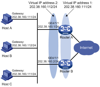
· In the segment 202.38.160.0/24, some hosts use 202.38.160.111/24 as their default gateway and some hosts use 202.38.160.112/24 as their default gateway.
· Load sharing and mutual backup between default gateways can be implemented by using VRRP groups.
Figure 14 Network diagram
Configuration procedure
1. Configure Router A:
<RouterA> system-view
[RouterA] interface GigabitEthernet 4/1/1
[RouterA-GigabitEthernet4/1/1] ip address 202.38.160.1 255.255.255.0
# Create VRRP group 1 and configure its virtual IP address as 202.38.160.111.
[RouterA-GigabitEthernet4/1/1] vrrp vrid 1 virtual-ip 202.38.160.111
# Set the priority of Router A in VRRP group 1 to 110, which is higher than that of Router B (100), so that Router A can become the master in VRRP group 1.
[RouterA-GigabitEthernet4/1/1] vrrp vrid 1 priority 110
# Create VRRP group 2 and configure its virtual IP address as 202.38.160.112.
[RouterA-GigabitEthernet4/1/1] vrrp vrid 2 virtual-ip 202.38.160.112
2. Configure Router B:
<RouterB> system-view
[RouterB] interface GigabitEthernet 4/1/1
[RouterB-GigabitEthernet4/1/1] ip address 202.38.160.2 255.255.255.0
# Create VRRP group 1 and configure its virtual IP address as 202.38.160.111.
[RouterB-GigabitEthernet4/1/1] vrrp vrid 1 virtual-ip 202.38.160.111
# Create VRRP group 2 and configure its virtual IP address as 202.38.160.112.
[RouterB-GigabitEthernet4/1/1] vrrp vrid 2 virtual-ip 202.38.160.112
# Set the priority of router B in VRRP group 2 to 110, which is higher than that of Router A (100), so that Router B can become the master in VRRP group 2.
[RouterB-GigabitEthernet4/1/1] vrrp vrid 2 priority 110
3. Verify the configuration:
To verify your configuration, use the display vrrp verbose command.
# Display the detailed information of the VRRP group on Router A.
[RouterA-GigabitEthernet4/1/1] display vrrp verbose
IPv4 Standby Information:
Run Mode : Standard
Run Method : Virtual MAC
Total number of virtual routers : 2
Interface GigabitEthernet4/1/1
VRID : 1 Adver Timer : 1
Admin Status : Up State : Master
Config Pri : 110 Running Pri : 110
Preempt Mode : Yes Delay Time : 0
Auth Type : None
Virtual IP : 202.38.160.111
Virtual MAC : 0000-5e00-0101
Master IP : 202.38.160.1
Interface GigabitEthernet4/1/1
VRID : 2 Adver Timer : 1
Admin Status : Up State : Backup
Config Pri : 100 Running Pri : 100
Preempt Mode : Yes Delay Time : 0
Auth Type : None
Virtual IP : 202.38.160.112
Master IP : 202.38.160.2
# Display the detailed information of the VRRP group on Router B.
[RouterB-GigabitEthernet4/1/1] display vrrp verbose
IPv4 Standby Information:
Run Mode : Standard
Run Method : Virtual MAC
Total number of virtual routers : 2
Interface GigabitEthernet4/1/1
VRID : 1 Adver Timer : 1
Admin Status : Up State : Backup
Config Pri : 100 Running Pri : 100
Preempt Mode : Yes Delay Time : 0
Auth Type : None
Virtual IP : 202.38.160.111
Master IP : 202.38.160.1
Interface GigabitEthernet4/1/1
VRID : 2 Adver Timer : 1
Admin Status : Up State : Master
Config Pri : 110 Running Pri : 110
Preempt Mode : Yes Delay Time : 0
Auth Type : None
Virtual IP : 202.38.160.112
Virtual MAC : 0000-5e00-0102
Master IP : 202.38.160.2
The output shows that in VRRP group 1 Router A is the master, Router B is the backup and the host with the default gateway of 202.38.160.111/24 accesses the Internet through Router A; in VRRP group 2 Router A is the backup, Router B is the master and the host with the default gateway of 202.38.160.112/24 accesses the Internet through Router B.
|
|
NOTE: To implement load balancing between the VRRP groups, be sure to configure the default gateway as 202.38.160.111 or 202.38.160.112 on the hosts on network segment 202.38.160.0/24. |
VRRP load balancing mode configuration example
Network requirements
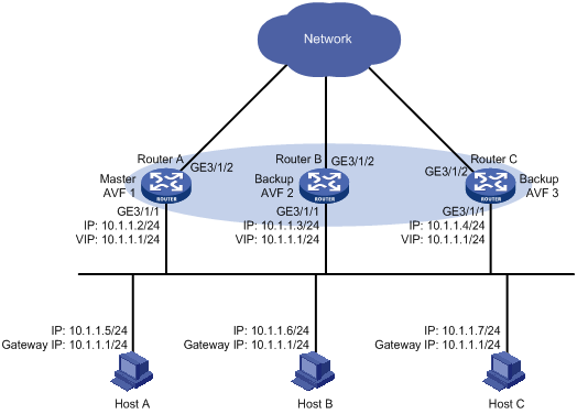
· Router A, Router B, and Router C belong to VRRP group 1 with the virtual IP address of 10.1.1.1/24.
· Hosts on network segment 10.1.1.0/24 use 10.1.1.1/24 as their default gateway. Use the VRRP group to make sure that when a gateway (Router A, Router B, or Router C) fails, the hosts on the LAN can access the external network through another gateway.
· VRRP group 1 works in load balancing mode to make good use of network resources.
· Configure a track entry on Router A, Router B, and Router C respectively to monitor their own GigabitEthernet 3/1/2. When the interface on Router A, Router B, or Router C fails, the weight of the corresponding router decreases so that another router with a higher weight can take over.
Figure 15 Network diagram
Configuration procedure
1. Configure Router A:
# Configure VRRP to work in load balancing mode.
<RouterA> system-view
[RouterA] vrrp mode load-balance
# Create VRRP group 1 and configure its virtual IP address as 10.1.1.1.
[RouterA] interface GigabitEthernet 3/1/1
[RouterA-GigabitEthernet3/1/1] ip address 10.1.1.2 24
[RouterA-GigabitEthernet3/1/1] vrrp vrid 1 virtual-ip 10.1.1.1
# Set the priority of Router A in VRRP group 1 to 120, which is higher than that of Router B (110) and that of Router C (100), so that Router A can become the master.
[RouterA-GigabitEthernet3/1/1] vrrp vrid 1 priority 120
# Configure Router A to work in preemptive mode so that it can become the master whenever it works normally. Configure the preemption delay as five seconds to avoid frequent status switchover.
[RouterA-GigabitEthernet3/1/1] vrrp vrid 1 preempt-mode timer delay 5
[RouterA-GigabitEthernet3/1/1] quit
# Create track entry 1 to associate with the physical status of GigabitEthernet 3/1/2 on Router A. When the track entry becomes negative, it means that the interface fails.
[RouterA] track 1 interface GigabitEthernet 3/1/2
# Configure the VFs to monitor track entry 1, making the weight of Router A decrease by more than 245 (250 in this example) when track entry 1 turns to negative. In such a case, another router with a higher weight can take over.
[RouterA] interface GigabitEthernet 3/1/1
[RouterA-GigabitEthernet3/1/1] vrrp vrid 1 weight track 1 reduced 250
2. Configure Router B:
# Configure VRRP to work in load balancing mode.
<RouterB> system-view
[RouterB] vrrp mode load-balance
# Create VRRP group 1 and configure its virtual IP address as 10.1.1.1.
[RouterB] interface GigabitEthernet 3/1/1
[RouterB-GigabitEthernet3/1/1] ip address 10.1.1.3 24
[RouterB-GigabitEthernet3/1/1] vrrp vrid 1 virtual-ip 10.1.1.1
# Set the priority of Router B in VRRP group 1 to 110, which is higher than that of Router C (100), so that Router B can become the master when Router A fails.
[RouterB-GigabitEthernet3/1/1] vrrp vrid 1 priority 110
# Set Router B to work in preemptive mode and set the preemption delay to five seconds.
[RouterB-GigabitEthernet3/1/1] vrrp vrid 1 preempt-mode timer delay 5
[RouterB-GigabitEthernet3/1/1] quit
# Create track entry 1 to associate with the physical status of GigabitEthernet 3/1/2 on Router B. When the track entry becomes negative, it means that the interface fails.
[RouterB] track 1 interface GigabitEthernet 3/1/2
# Configure the VFs to monitor track entry 1, making the weight of Router B decrease by more than 245 (250 in this example) when track entry 1 turns to negative. In such a case, another router with a higher weight can take over.
[RouterB] interface GigabitEthernet 3/1/1
[RouterB-GigabitEthernet3/1/1] vrrp vrid 1 weight track 1 reduced 250
3. Configure Router C:
# Configure VRRP to work in load balancing mode.
<RouterC> system-view
[RouterC] vrrp mode load-balance
# Create VRRP group 1 and configure its virtual IP address as 10.1.1.1.
[RouterC] interface GigabitEthernet 3/1/1
[RouterC-GigabitEthernet3/1/1] ip address 10.1.1.4 24
[RouterC-GigabitEthernet3/1/1] vrrp vrid 1 virtual-ip 10.1.1.1
# Set Router C to work in preemptive mode and set the preemption delay to five seconds.
[RouterC-GigabitEthernet3/1/1] vrrp vrid 1 preempt-mode timer delay 5
[RouterC-GigabitEthernet3/1/1] quit
# Create track entry 1 to associate with the physical status of GigabitEthernet 3/1/2 on Router C. When the track entry becomes negative, it means that the interface fails.
[RouterC] track 1 interface GigabitEthernet 3/1/2
# Configure the VFs to monitor track entry 1, making the weight of Router C decrease by more than 245 (250 in this example) when track entry 1 turns to negative. In such a case, another router with a higher weight can take over.
[RouterC] interface GigabitEthernet 3/1/1
[RouterC-GigabitEthernet3/1/1] vrrp vrid 1 weight track 1 reduced 250
4. Verify the configuration:
After the configuration, Host A can ping the external network. To verify the configuration, use the display vrrp verbose command.
# Display the detailed information of VRRP group 1 on Router A.
[RouterA-GigabitEthernet3/1/1] display vrrp verbose
IPv4 Standby Information:
Run Mode : Load Balance
Run Method : Virtual MAC
Total number of virtual routers : 1
Interface GigabitEthernet3/1/1
VRID : 1 Adver Timer : 1
Admin Status : Up State : Master
Config Pri : 120 Running Pri : 120
Preempt Mode : Yes Delay Time : 5
Auth Type : None
Virtual IP : 10.1.1.1
Member IP List : 10.1.1.2 (Local, Master)
10.1.1.3 (Backup)
10.1.1.4 (Backup)
Forwarder Information: 3 Forwarders 1 Active
Config Weight : 255
Running Weight : 255
Forwarder 01
State : Active
Virtual MAC : 000f-e2ff-0011 (Owner)
Owner ID : 0000-5e01-1101
Priority : 255
Active : local
Forwarder 02
State : Listening
Virtual MAC : 000f-e2ff-0012 (Learnt)
Owner ID : 0000-5e01-1103
Priority : 127
Active : 10.1.1.3
Forwarder 03
State : Listening
Virtual MAC : 000f-e2ff-0013 (Learnt)
Owner ID : 0000-5e01-1105
Priority : 127
Active : 10.1.1.4
Forwarder Weight Track Information:
Track Object : 1 State : Positive Weight Reduced : 250
# Display the detailed information of VRRP group 1 on Router B.
[RouterB-GigabitEthernet3/1/1] display vrrp verbose
IPv4 Standby Information:
Run Mode : Load Balance
Run Method : Virtual MAC
Total number of virtual routers : 1
Interface GigabitEthernet3/1/1
VRID : 1 Adver Timer : 1
Admin Status : Up State : Backup
Config Pri : 110 Running Pri : 110
Preempt Mode : Yes Delay Time : 5
Auth Type : None
Virtual IP : 10.1.1.1
Member IP List : 10.1.1.3 (Local, Backup)
10.1.1.2 (Master)
10.1.1.4 (Backup)
Forwarder Information: 3 Forwarders 1 Active
Config Weight : 255
Running Weight : 255
Forwarder 01
State : Listening
Virtual MAC : 000f-e2ff-0011 (Learnt)
Owner ID : 0000-5e01-1101
Priority : 127
Active : 10.1.1.2
Forwarder 02
State : Active
Virtual MAC : 000f-e2ff-0012 (Owner)
Owner ID : 0000-5e01-1103
Priority : 255
Active : local
Forwarder 03
State : Listening
Virtual MAC : 000f-e2ff-0013 (Learnt)
Owner ID : 0000-5e01-1105
Priority : 127
Active : 10.1.1.4
Forwarder Weight Track Information:
Track Object : 1 State : Positive Weight Reduced : 250
# Display the detailed information of VRRP group 1 on Router C.
[RouterC-GigabitEthernet3/1/1] display vrrp verbose
IPv4 Standby Information:
Run Mode : Load Balance
Run Method : Virtual MAC
Total number of virtual routers : 1
Interface GigabitEthernet3/1/1
VRID : 1 Adver Timer : 1
Admin Status : Up State : Backup
Config Pri : 100 Running Pri : 100
Preempt Mode : Yes Delay Time : 5
Auth Type : None
Virtual IP : 10.1.1.1
Member IP List : 10.1.1.4 (Local, Backup)
10.1.1.2 (Master)
10.1.1.3 (Backup)
Forwarder Information: 3 Forwarders 1 Active
Config Weight : 255
Running Weight : 255
Forwarder 01
State : Listening
Virtual MAC : 000f-e2ff-0011 (Learnt)
Owner ID : 0000-5e01-1101
Priority : 127
Active : 10.1.1.2
Forwarder 02
State : Listening
Virtual MAC : 000f-e2ff-0012 (Learnt)
Owner ID : 0000-5e01-1103
Priority : 127
Active : 10.1.1.3
Forwarder 03
State : Active
Virtual MAC : 000f-e2ff-0013 (Owner)
Owner ID : 0000-5e01-1105
Priority : 255
Active : local
Forwarder Weight Track Information:
Track Object : 1 State : Positive Weight Reduced : 250
The output shows that in VRRP group 1, Router A is the master and Router B and Router C are the backups. Each router has one AVF and two LVFs that act as the backups.
# When GigabitEthernet 3/1/2 on Router A fails, use the display vrrp verbose command to display the detailed information of VRRP group 1 on Router A.
[RouterA-GigabitEthernet3/1/1] display vrrp verbose
IPv4 Standby Information:
Run Mode : Load Balance
Run Method : Virtual MAC
Total number of virtual routers : 1
Interface GigabitEthernet3/1/1
VRID : 1 Adver Timer : 1
Admin Status : Up State : Master
Config Pri : 120 Running Pri : 120
Preempt Mode : Yes Delay Time : 5
Auth Type : None
Virtual IP : 10.1.1.1
Member IP List : 10.1.1.2 (Local, Master)
10.1.1.3 (Backup)
10.1.1.4 (Backup)
Forwarder Information: 3 Forwarders 0 Active
Config Weight : 255
Running Weight : 5
Forwarder 01
State : Initialize
Virtual MAC : 000f-e2ff-0011 (Owner)
Owner ID : 0000-5e01-1101
Priority : 0
Active : 10.1.1.4
Forwarder 02
State : Initialize
Virtual MAC : 000f-e2ff-0012 (Learnt)
Owner ID : 0000-5e01-1103
Priority : 0
Active : 10.1.1.3
Forwarder 03
State : Initialize
Virtual MAC : 000f-e2ff-0013 (Learnt)
Owner ID : 0000-5e01-1105
Priority : 0
Active : 10.1.1.4
Forwarder Weight Track Information:
Track Object : 1 State : Negative Weight Reduced : 250
# Use the display vrrp verbose command to display the detailed information of VRRP group 1 on Router C.
[RouterC-GigabitEthernet3/1/1] display vrrp verbose
IPv4 Standby Information:
Run Mode : Load Balance
Run Method : Virtual MAC
Total number of virtual routers : 1
Interface GigabitEthernet3/1/1
VRID : 1 Adver Timer : 1
Admin Status : Up State : Backup
Config Pri : 100 Running Pri : 100
Preempt Mode : Yes Delay Time : 5
Auth Type : None
Virtual IP : 10.1.1.1
Member IP List : 10.1.1.4 (Local, Backup)
10.1.1.2 (Master)
10.1.1.3 (Backup)
Forwarder Information: 3 Forwarders 2 Active
Config Weight : 255
Running Weight : 255
Forwarder 01
State : Active
Virtual MAC : 000f-e2ff-0011 (Take Over)
Owner ID : 0000-5e01-1101
Priority : 85
Active : local
Redirect Time : 93 secs
Time-out Time : 1293 secs
Forwarder 02
State : Listening
Virtual MAC : 000f-e2ff-0012 (Learnt)
Owner ID : 0000-5e01-1103
Priority : 85
Active : 10.1.1.3
Forwarder 03
State : Active
Virtual MAC : 000f-e2ff-0013 (Owner)
Owner ID : 0000-5e01-1105
Priority : 255
Active : local
Forwarder Weight Track Information:
Track Object : 1 State : Positive Weight Reduced : 250
The output shows that when GigabitEthernet 3/1/2 on Router A fails, the weight of the AVF on Router A decreases to 5, which is lower than the lower limit of failure. All VFs on Router A turn to initialized state and cannot be used for packet forwarding. The VF corresponding to MAC address 000f-e2ff-0011 on Router C becomes the AVF, and Router C takes over Router A for packet forwarding.
# When the timeout timer (about 1800 seconds) expires, display the detailed information of VRRP group 1 on Router C.
[RouterC-GigabitEthernet3/1/1] display vrrp verbose
IPv4 Standby Information:
Run Mode : Load Balance
Run Method : Virtual MAC
Total number of virtual routers : 1
Interface GigabitEthernet3/1/1
VRID : 1 Adver Timer : 1
Admin Status : Up State : Backup
Config Pri : 100 Running Pri : 100
Preempt Mode : Yes Delay Time : 5
Auth Type : None
Virtual IP : 10.1.1.1
Member IP List : 10.1.1.4 (Local, Backup)
10.1.1.2 (Master)
10.1.1.3 (Backup)
Forwarder Information: 2 Forwarders 1 Active
Config Weight : 255
Running Weight : 255
Forwarder 02
State : Listening
Virtual MAC : 000f-e2ff-0012 (Learnt)
Owner ID : 0000-5e01-1103
Priority : 127
Active : 10.1.1.3
Forwarder 03
State : Active
Virtual MAC : 000f-e2ff-0013 (Owner)
Owner ID : 0000-5e01-1105
Priority : 255
Active : local
Forwarder Weight Track Information:
Track Object : 1 State : Positive Weight Reduced : 250
The output shows that when the timeout timer expires, the VF corresponding to virtual MAC address 000f-e2ff-0011 is removed, and does not forward the packets destined for the MAC address any more.
# When Router A fails, use the display vrrp verbose command to display the detailed information of VRRP group 1 on Router B.
[RouterB-GigabitEthernet3/1/1] display vrrp verbose
IPv4 Standby Information:
Run Mode : Load Balance
Run Method : Virtual MAC
Total number of virtual routers : 1
Interface GigabitEthernet3/1/1
VRID : 1 Adver Timer : 1
Admin Status : Up State : Master
Config Pri : 110 Running Pri : 110
Preempt Mode : Yes Delay Time : 5
Auth Type : None
Virtual IP : 10.1.1.1
Member IP List : 10.1.1.3 (Local, Master)
10.1.1.4 (Backup)
Forwarder Information: 2 Forwarders 1 Active
Config Weight : 255
Running Weight : 255
Forwarder 02
State : Active
Virtual MAC : 000f-e2ff-0012 (Owner)
Owner ID : 0000-5e01-1103
Priority : 255
Active : local
Forwarder 03
State : Listening
Virtual MAC : 000f-e2ff-0013 (Learnt)
Owner ID : 0000-5e01-1105
Priority : 127
Active : 10.1.1.4
Forwarder Weight Track Information:
Track Object : 1 State : Positive Weight Reduced : 250
The output shows that when Router A fails, Router B becomes the master because its priority is higher than that of Router C.
IPv6-based VRRP configuration examples
This section provides these configuration examples:
· Single VRRP group configuration example
· VRRP interface tracking configuration example
· Multiple VRRP groups configuration example
· VRRP load balancing mode configuration example
Single VRRP group configuration example
Network requirements
· Router A and Router B belong to VRRP group 1 with the virtual IPv6 addresses of 1::10/64 and FE80::10.
· Host A wants to access Host B on the Internet. Host A learns 1::10/64 as its default gateway through the RA messages sent by the routers.
· When Router A operates normally, packets sent from Host A to Host B are forwarded by Router A; when Router A fails, packets sent from Host A to Host B are forwarded by Router B.
Figure 16 Network diagram
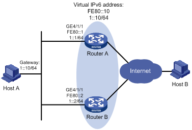
Configuration procedure
1. Configure Router A:
<RouterA> system-view
[RouterA] ipv6
[RouterA] interface GigabitEthernet 4/1/1
[RouterA-GigabitEthernet4/1/1] ipv6 address fe80::1 link-local
[RouterA-GigabitEthernet4/1/1] ipv6 address 1::1 64
# Create a VRRP group 1 and set its virtual IPv6 addresses to FE80::10 and 1::10.
[RouterA-GigabitEthernet4/1/1] vrrp ipv6 vrid 1 virtual-ip fe80::10 link-local
[RouterA-GigabitEthernet4/1/1] vrrp ipv6 vrid 1 virtual-ip 1::10
# Configure the priority of Router A in VRRP group 1 as 110, which is higher than that of Router B (100), so that Router A can become the master.
[RouterA-GigabitEthernet4/1/1] vrrp ipv6 vrid 1 priority 110
# Configure Router A to work in preemptive mode so that it can become the master whenever it works normally; configure the preemption delay as five seconds to avoid frequent status switchover.
[RouterA-GigabitEthernet4/1/1] vrrp ipv6 vrid 1 preempt-mode timer delay 5
# Enable Router A to send RA messages, so that Host A can learn the default gateway address.
[RouterA-GigabitEthernet4/1/1] undo ipv6 nd ra halt
2. Configure Router B:
<RouterB> system-view
[RouterB] ipv6
[RouterB] interface GigabitEthernet 4/1/1
[RouterB-GigabitEthernet4/1/1] ipv6 address fe80::2 link-local
[RouterB-GigabitEthernet4/1/1] ipv6 address 1::2 64
# Create a VRRP group 1 and set its virtual IPv6 addresses to FE80::10 and 1::10.
[RouterB-GigabitEthernet4/1/1] vrrp ipv6 vrid 1 virtual-ip fe80::10 link-local
[RouterB-GigabitEthernet4/1/1] vrrp ipv6 vrid 1 virtual-ip 1::10
# Configure Router B to work in preemptive mode, with the preemption delay set to 5 seconds.
[RouterB-GigabitEthernet4/1/1] vrrp ipv6 vrid 1 preempt-mode timer delay 5
# Enable Router B to send RA messages, so that Host A can learns the default gateway address.
[RouterB-GigabitEthernet4/1/1] undo ipv6 nd ra halt
3. Verify the configuration:
After the configuration, Host B can be pinged successfully on Host A. To verify your configuration, use the display vrrp ipv6 verbose command.
# Display the detailed information of VRRP group 1 on Router A.
[RouterA-GigabitEthernet4/1/1] display vrrp ipv6 verbose
IPv6 Standby Information:
Run Mode : Standard
Run Method : Virtual MAC
Total number of virtual routers : 1
Interface GigabitEthernet4/1/1
VRID : 1 Adver Timer : 100
Admin Status : Up State : Master
Config Pri : 110 Running Pri : 110
Preempt Mode : Yes Delay Time : 5
Auth Type : None
Virtual IP : FE80::10
1::10
Virtual MAC : 0000-5e00-0201
Master IP : FE80::1
# Display the detailed information of VRRP group 1 on Router B.
[RouterB-GigabitEthernet4/1/1] display vrrp ipv6 verbose
IPv6 Standby Information:
Run Mode : Standard
Run Method : Virtual MAC
Total number of virtual routers : 1
Interface GigabitEthernet4/1/1
VRID : 1 Adver Timer : 100
Admin Status : Up State : Backup
Config Pri : 100 Running Pri : 100
Preempt Mode : Yes Delay Time : 5
Auth Type : None
Virtual IP : FE80::10
1::10
Master IP : FE80::1
The output shows that in VRRP group 1 Router A is the master, Router B is the backup and packets sent from Host A to Host B are forwarded by Router A.
When Router A fails, you can still ping Router B successfully on Host A. To view the detailed information of the VRRP group on Router B, use the display vrrp ipv6 verbose command.
# When Router A fails, display the detailed information of VRRP group 1 on Router B.
[RouterB-GigabitEthernet4/1/1] display vrrp ipv6 verbose
IPv6 Standby Information:
Run Mode : Standard
Run Method : Virtual MAC
Total number of virtual routers : 1
Interface GigabitEthernet4/1/1
VRID : 1 Adver Timer : 100
Admin Status : Up State : Master
Config Pri : 100 Running Pri : 100
Preempt Mode : Yes Delay Time : 5
Auth Type : None
Virtual IP : FE80::10
1::10
Virtual MAC : 0000-5e00-0201
Master IP : FE80::2
The output shows that when Router A fails, Router B becomes the master, and packets sent from Host A to Host B are forwarded by Router B.
VRRP interface tracking configuration example
Network requirements
· Router A and Router B belong to VRRP group 1 with the virtual IPv6 addresses of 1::10/64 and FE80::10.
· Host A wants to access Host B on the Internet, and learns 1::10/64 as its default gateway through RA messages sent by the routers.
· When Router A operates normally, packets sent from Host A to Host B are forwarded by Router A. If interface GigabitEthernet 4/1/2 through which Router A connects to the internet is not available, packets sent from Host A to Host B are forwarded by Router B.
Figure 17 Network diagram
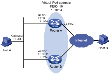
Configuration procedure
1. Configure Router A:
<RouterA> system-view
[RouterA] ipv6
[RouterA] interface GigabitEthernet 4/1/1
[RouterA-GigabitEthernet4/1/1] ipv6 address fe80::1 link-local
[RouterA-GigabitEthernet4/1/1] ipv6 address 1::1 64
# Create a VRRP group 1 and set its virtual IPv6 addresses to FE80::10 and 1::10.
[RouterA-GigabitEthernet4/1/1] vrrp ipv6 vrid 1 virtual-ip fe80::10 link-local
[RouterA-GigabitEthernet4/1/1] vrrp ipv6 vrid 1 virtual-ip 1::10
# Configure the priority of Router A in VRRP group 1 as 110, which is higher than that of Router B (100), so that Router A can become the master.
[RouterA-GigabitEthernet4/1/1] vrrp ipv6 vrid 1 priority 110
# Set the authentication mode of VRRP group 1 as simple and authentication key to hello.
[RouterA-GigabitEthernet4/1/1] vrrp ipv6 vrid 1 authentication-mode simple hello
# Set the interval on Router A for sending VRRP advertisements to 500 centiseconds.
[RouterA-GigabitEthernet4/1/2] vrrp ipv6 vrid 1 timer advertise 500
# Configure Router A to work in preemptive mode, so that it can become the master whenever it works normally; configure the preemption delay as five seconds to avoid frequent status switchover.
[RouterA-GigabitEthernet4/1/1] vrrp ipv6 vrid 1 preempt-mode timer delay 5
# Set interface GigabitEthernet 4/1/2 on Router A to be tracked, and configure the amount by which the priority value decreases to be more than 10 (30 in this example), so that when GigabitEthernet 4/1/2 fails, the priority of Router A in VRRP group 1 decreases to a value lower than 100 and thus Router B can become the master.
[RouterA-GigabitEthernet4/1/1] vrrp ipv6 vrid 1 track interface GigabitEthernet 4/1/1 reduced 30
# Enable Router A to send RA messages, so that Host A can learn the default gateway address.
[RouterA-GigabitEthernet4/1/1] undo ipv6 nd ra halt
2. Configure Router B:
<RouterB> system-view
[RouterB] ipv6
[RouterB] interface GigabitEthernet 4/1/1
[RouterB-GigabitEthernet4/1/1] ipv6 address fe80::2 link-local
[RouterB-GigabitEthernet4/1/1] ipv6 address 1::2 64
# Create a VRRP group 1 and set its virtual IPv6 addresses to FE80::10 and 1::10.
[RouterB-GigabitEthernet4/1/1] vrrp ipv6 vrid 1 virtual-ip fe80::10 link-local
[RouterB-GigabitEthernet4/1/1] vrrp ipv6 vrid 1 virtual-ip 1::10
# Set the authentication mode of VRRP group 1 as simple and authentication key as hello.
[RouterB-GigabitEthernet4/1/1] vrrp ipv6 vrid 1 authentication-mode simple hello
# Set the interval between sending VRRP advertisements to 500 centiseconds.
[RouterB-GigabitEthernet4/1/2] vrrp ipv6 vrid 1 timer advertise 500
# Configure Router B to work in preemptive mode, so that Router B can become the master after the priority of Router A decreases to a value lower than 100. Configure the preemption delay as five seconds to avoid frequent status switchover.
[RouterB-GigabitEthernet4/1/1] vrrp ipv6 vrid 1 preempt-mode timer delay 5
# Enable Router B to send RA messages, so that Host A can learn the default gateway address.
[RouterB-GigabitEthernet4/1/1] undo ipv6 nd ra halt
3. Verify the configuration:
After the configuration, Host B can be pinged successfully on Host A. To verify your configuration, use the display vrrp ipv6 verbose command.
# Display the detailed information of VRRP group 1 on Router A.
[RouterA-GigabitEthernet4/1/1] display vrrp ipv6 verbose
IPv6 Standby Information:
Run Mode : Standard
Run Method : Virtual MAC
Total number of virtual routers : 1
Interface GigabitEthernet4/1/1
VRID : 1 Adver Timer : 500
Admin Status : Up State : Master
Config Pri : 110 Running Pri : 110
Preempt Mode : Yes Delay Time : 5
Auth Type : Simple Key : hello
Virtual IP : FE80::10
1::10
Virtual MAC : 0000-5e00-0201
Master IP : FE80::1
VRRP Track Information:
Track Interface: GE4/1/2 State : Up Pri Reduced : 30
# Display the detailed information of VRRP group 1 on Router B.
[RouterB-GigabitEthernet4/1/1] display vrrp ipv6 verbose
IPv6 Standby Information:
Run Mode : Standard
Run Method : Virtual MAC
Total number of virtual routers : 1
Interface GigabitEthernet4/1/1
VRID : 1 Adver Timer : 500
Admin Status : Up State : Backup
Config Pri : 100 Running Pri : 100
Preempt Mode : Yes Delay Time : 5
Auth Type : Simple Key : hello
Virtual IP : FE80::10
1::10
Master IP : FE80::1
The output shows that in VRRP group 1 Router A is the master, Router B is the backup and packets sent from Host A to Host B are forwarded by Router A.
When interface GigabitEthernet 4/1/2 on Router A is not available, you can still ping Host B on Host A. To view the detailed information of the VRRP group, use the display vrrp ipv6 verbose command.
# When interface GigabitEthernet 4/1/2 on Router A fails, display the detailed information of VRRP group 1 on Router A.
[RouterA-GigabitEthernet4/1/1] display vrrp ipv6 verbose
IPv6 Standby Information:
Run Mode : Standard
Run Method : Virtual MAC
Total number of virtual routers : 1
Interface GigabitEthernet4/1/1
VRID : 1 Adver Timer : 500
Admin Status : Up State : Backup
Config Pri : 110 Running Pri : 80
Preempt Mode : Yes Delay Time : 5
Auth Type : Simple Key : hello
Virtual IP : FE80::10
1::10
Master IP : FE80::2
VRRP Track Information:
Track Interface: GE4/1/2 State : Down Pri Reduced : 30
# When interface GigabitEthernet 4/1/2 on Router A fails, display the detailed information of VRRP group 1 on Router B.
[RouterB-GigabitEthernet4/1/1] display vrrp ipv6 verbose
IPv6 Standby Information:
Run Mode : Standard
Run Method : Virtual MAC
Total number of virtual routers : 1
Interface GigabitEthernet4/1/1
VRID : 1 Adver Timer : 500
Admin Status : Up State : Master
Config Pri : 100 Running Pri : 100
Preempt Mode : Yes Delay Time : 5
Auth Type : Simple Key : hello
Virtual IP : FE80::10
1::10
Virtual MAC : 0000-5e00-0201
Master IP : FE80::2
The output shows that when interface GigabitEthernet 4/1/2 on Router A is not available, the priority of Router A reduces to 80 and it becomes the backup. Router B becomes the master and packets sent from Host A to Host B are forwarded by Router B.
Multiple VRRP groups configuration example
Network requirements
· In the network, some hosts use 1::10/64 as their default gateway and some hosts use 1::20/64 as their default gateway.
· Load sharing and mutual backup between default gateways can be implemented by using VRRP groups.
Figure 18 Network diagram
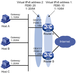
Configuration procedure
1. Configure Router A:
<RouterA> system-view
[RouterA] ipv6
[RouterA] interface GigabitEthernet 4/1/1
[RouterA-GigabitEthernet4/1/1] ipv6 address fe80::1 link-local
[RouterA-GigabitEthernet4/1/1] ipv6 address 1::1 64
# Create VRRP group 1 and set its virtual IPv6 addresses to FE80::10 and 1::10.
[RouterA-GigabitEthernet4/1/1] vrrp ipv6 vrid 1 virtual-ip fe80::10 link-local
[RouterA-GigabitEthernet4/1/1] vrrp ipv6 vrid 1 virtual-ip 1::10
# Set the priority of Router A in VRRP group 1 to 110, which is higher than that of Router B (100), so that Router A can become the master in VRRP group 1.
[RouterA-GigabitEthernet4/1/1] vrrp ipv6 vrid 1 priority 110
# Create VRRP group 2 set its virtual IPv6 addresses to FE80::20 and 1::20.
[RouterA-GigabitEthernet4/1/1] vrrp ipv6 vrid 2 virtual-ip fe80::20 link-local
[RouterA-GigabitEthernet4/1/1] vrrp ipv6 vrid 2 virtual-ip 1::20
# Enable Router A to send RA messages.
[RouterA-GigabitEthernet4/1/1] undo ipv6 nd ra halt
2. Configure Router B:
<RouterB> system-view
[RouterB] ipv6
[RouterB] interface GigabitEthernet 4/1/1
[RouterB-GigabitEthernet4/1/1] ipv6 address fe80::2 link-local
[RouterB-GigabitEthernet4/1/1] ipv6 address 1::2 64
# Create VRRP group 1 and set its virtual IPv6 addresses to FE80::10 and 1::10.
[RouterB-GigabitEthernet4/1/1] vrrp ipv6 vrid 1 virtual-ip fe80::10 link-local
[RouterB-GigabitEthernet4/1/1] vrrp ipv6 vrid 1 virtual-ip 1::10
# Create VRRP group 2 set its virtual IPv6 addresses to FE80::20 and 1::20.
[RouterB-GigabitEthernet4/1/1] vrrp ipv6 vrid 2 virtual-ip fe80::20 link-local
[RouterB-GigabitEthernet4/1/1] vrrp ipv6 vrid 2 virtual-ip 1::20
# Set the priority of Router B in VRRP group 2 to 110, which is higher than that of Router A (100), so that Router B can become the master in VRRP group 2.
[RouterB-GigabitEthernet4/1/1] vrrp ipv6 vrid 2 priority 110
# Enable Router B to send RA messages.
[RouterB-GigabitEthernet4/1/1] undo ipv6 nd ra halt
3. Verify the configuration:
To verify your configuration, use the display vrrp ipv6 verbose command.
# Display the detailed information of the VRRP group on Router A.
[RouterA-GigabitEthernet4/1/1] display vrrp ipv6 verbose
IPv6 Standby Information:
Run Mode : Standard
Run Method : Virtual MAC
Total number of virtual routers : 2
Interface GigabitEthernet4/1/1
VRID : 1 Adver Timer : 100
Admin Status : Up State : Master
Config Pri : 110 Running Pri : 110
Preempt Mode : Yes Delay Time : 0
Auth Type : None
Virtual IP : FE80::10
1::10
Virtual MAC : 0000-5e00-0201
Master IP : FE80::1
Interface GigabitEthernet4/1/1
VRID : 2 Adver Timer : 100
Admin Status : Up State : Backup
Config Pri : 100 Running Pri : 100
Preempt Mode : Yes Delay Time : 0
Auth Type : None
Virtual IP : FE80::20
1::20
Master IP : FE80::2
# Display the detailed information of the VRRP group on Router B.
[RouterB-GigabitEthernet4/1/1] display vrrp ipv6 verbose
IPv6 Standby Information:
Run Mode : Standard
Run Method : Virtual MAC
Total number of virtual routers : 2
Interface GigabitEthernet4/1/1
VRID : 1 Adver Timer : 100
Admin Status : Up State : Backup
Config Pri : 100 Running Pri : 100
Preempt Mode : Yes Delay Time : 0
Auth Type : None
Virtual IP : FE80::10
1::10
Master IP : FE80::1
Interface GigabitEthernet4/1/1
VRID : 2 Adver Timer : 100
Admin Status : Up State : Master
Config Pri : 110 Running Pri : 110
Preempt Mode : Yes Delay Time : 0
Auth Type : None
Virtual IP : FE80::20
1::20
Virtual MAC : 0000-5e00-0202
Master IP : FE80::2
The output shows that in VRRP group 1, Router A is the master, Router B is the backup and the host with the default gateway of 1::10/64 accesses the Internet through Router A; in VRRP group 2, Router A is the backup, Router B is the master and the host with the default gateway of 1::20/64 accesses the Internet through Router B.
|
|
NOTE: To implement load balancing between the VRRP groups, be sure to configure the default gateway 1::10 or 1::20on the hosts on the subnet 1::/64. |
VRRP load balancing mode configuration example
Network requirements
· Router A, Router B, and Router C belong to VRRP group 1 with the virtual IPv6 addresses of FE80::10 and 1::10.
· Hosts on network segment 1::/64 learn FE80::10 as their default gateway through RA messages sent by the routers. Configure the VRRP group to make sure that when a gateway (Router A, Router B, or Router C) fails, the hosts on the LAN can access external networks through another gateway.
· VRRP group 1 works in load balancing mode to make good use of network resources.
· Configure a track entry on Router A, Router B, and Router C respectively to monitor their own GigabitEthernet 4/1/2. When the interface on Router A, Router B, or Router C fails, the weight of the corresponding router decreases so that another router with a higher weight can take over.
Figure 19 Network diagram
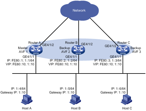
Configuration procedure
1. Configure Router A:
# Configure VRRP to work in load balancing mode.
<RouterA> system-view
[RouterA] vrrp mode load-balance
# Create VRRP group 1 and configure its virtual IPv6 addresses as FE80::10 and 1::10.
[RouterA] interface GigabitEthernet 4/1/1
[RouterA-GigabitEthernet4/1/1] ipv6 address fe80::1 link-local
[RouterA-GigabitEthernet4/1/1] ipv6 address 1::1 64
[RouterA-GigabitEthernet4/1/1] vrrp ipv6 vrid 1 virtual-ip fe80::10 link-local
[RouterA-GigabitEthernet4/1/1] vrrp ipv6 vrid 1 virtual-ip 1::10
# Set the priority of Router A in VRRP group 1 to 120, which is higher than that of Router B (110) and that of Router C (100), so that Router A can become the master.
[RouterA-GigabitEthernet4/1/1] vrrp ipv6 vrid 1 priority 120
# Configure Router A to work in preemptive mode so that it can become the master whenever it works normally; configure the preemption delay as five seconds to avoid frequent status switchover.
[RouterA-GigabitEthernet4/1/1] vrrp ipv6 vrid 1 preempt-mode timer delay 5
# Enable Router A to send RA messages so that hosts in network segment 1::/64 can learn the default gateway address.
[RouterA-GigabitEthernet4/1/1] undo ipv6 nd ra halt
[RouterA-GigabitEthernet4/1/1] quit
# Create track entry 1 to associate with the physical status of GigabitEthernet 4/1/2 on Router A. When the track entry becomes negative, it means that the interface fails.
[RouterA] track 1 interface GigabitEthernet 4/1/2
# Configure the VFs to monitor track entry 1, making the weight of Router A decrease by more than 245 (250 in this example) when track entry 1 turns to negative. In such a case, another router with a higher weight can take over.
[RouterA] interface GigabitEthernet 4/1/1
[RouterA-GigabitEthernet4/1/1] vrrp ipv6 vrid 1 weight track 1 reduced 250
2. Configure Router B:
# Configure VRRP to work in load balancing mode.
<RouterB> system-view
[RouterB] vrrp mode load-balance
# Create VRRP group 1 and configure its virtual IPv6 addresses as FE80::10 and 1::10.
[RouterB] interface GigabitEthernet 4/1/1
[RouterB-GigabitEthernet4/1/1] ipv6 address fe80::2 link-local
[RouterB-GigabitEthernet4/1/1] ipv6 address 1::2 64
[RouterB-GigabitEthernet4/1/1] vrrp ipv6 vrid 1 virtual-ip fe80::10 link-local
[RouterB-GigabitEthernet4/1/1] vrrp ipv6 vrid 1 virtual-ip 1::10
# Set the priority of Router B in VRRP group 1 to 110, which is higher than that of Router C (100) so that Router B can become the master when Router A fails.
[RouterB-GigabitEthernet4/1/1] vrrp ipv6 vrid 1 priority 110
# Set Router B to work in preemptive mode. The preemption delay is five seconds.
[RouterB-GigabitEthernet4/1/1] vrrp ipv6 vrid 1 preempt-mode timer delay 5
# Enable Router B to send RA messages, so that hosts in network segment 1::/64 can learn the default gateway address.
[RouterB-GigabitEthernet4/1/1] undo ipv6 nd ra halt
[RouterB-GigabitEthernet4/1/1] quit
# Create track entry 1 to associate with the physical status of GigabitEthernet 4/1/2 on Router B. When the track entry becomes negative, it means that the interface fails.
[RouterB] track 1 interface GigabitEthernet 4/1/2
# Configure the VFs to monitor track entry 1, making the weight of Router B decrease by more than 245 (250 in this example) when track entry 1 turns to negative. In such a case, another router with a higher weight can take over.
[RouterB] interface GigabitEthernet 4/1/1
[RouterB-GigabitEthernet4/1/1] vrrp ipv6 vrid 1 weight track 1 reduced 250
3. Configure Router C:
# Configure VRRP to work in load balancing mode.
<RouterC> system-view
[RouterC] vrrp mode load-balance
# Create VRRP group 1 and configure its virtual IPv6 addresses as FE80::10 and 1::10.
[RouterC] interface GigabitEthernet 4/1/1
[RouterC-GigabitEthernet4/1/1] ipv6 address fe80::3 link-local
[RouterC-GigabitEthernet4/1/1] ipv6 address 1::3 64
[RouterC-GigabitEthernet4/1/1] vrrp ipv6 vrid 1 virtual-ip fe80::10 link-local
[RouterC-GigabitEthernet4/1/1] vrrp ipv6 vrid 1 virtual-ip 1::10
# Set Router C to work in preemptive mode and set the preemption delay to five seconds.
[RouterC-GigabitEthernet4/1/1] vrrp ipv6 vrid 1 preempt-mode timer delay 5
# Enable Router C to send RA messages, so that hosts in network segment 1::/64 can learn the default gateway address.
[RouterC-GigabitEthernet4/1/1] undo ipv6 nd ra halt
[RouterC-GigabitEthernet4/1/1] quit
# Create track entry 1 to associate with the physical status of GigabitEthernet 4/1/2 on Router C. When the track entry becomes negative, it means that the interface fails.
[RouterC] track 1 interface GigabitEthernet 4/1/2
# Configure the VFs to monitor track entry 1, making the weight of Router C decrease by more than 245 (250 in this example) when track entry 1 turns to negative. In such a case, another router with a higher weight can take over.
[RouterC] interface GigabitEthernet 4/1/1
[RouterC-GigabitEthernet4/1/1] vrrp ipv6 vrid 1 weight track 1 reduced 250
4. Verify the configuration:
After the configuration, Host A can ping external networks successfully. To verify your configuration, use the display vrrp ipv6 verbose command.
# Display the detailed information of VRRP group 1 on Router A.
[RouterA-GigabitEthernet4/1/1] display vrrp ipv6 verbose
IPv6 Standby Information:
Run Mode : Load Balance
Run Method : Virtual MAC
Total number of virtual routers : 1
Interface GigabitEthernet4/1/1
VRID : 1 Adver Timer : 100
Admin Status : Up State : Master
Config Pri : 120 Running Pri : 120
Preempt Mode : Yes Delay Time : 5
Auth Type : None
Virtual IP : FE80::10
1::10
Member IP List : FE80::1 (Local, Master)
FE80::2 (Backup)
FE80::3 (Backup)
Forwarder Information: 3 Forwarders 1 Active
Config Weight : 255
Running Weight : 255
Forwarder 01
State : Active
Virtual MAC : 000f-e2ff-4011 (Owner)
Owner ID : 0000-5e01-1101
Priority : 255
Active : local
Forwarder 02
State : Listening
Virtual MAC : 000f-e2ff-4012 (Learnt)
Owner ID : 0000-5e01-1103
Priority : 127
Active : FE80::2
Forwarder 03
State : Listening
Virtual MAC : 000f-e2ff-4013 (Learnt)
Owner ID : 0000-5e01-1105
Priority : 127
Active : FE80::3
Forwarder Weight Track Information:
Track Object : 1 State : Positive Weight Reduced : 250
# Display the detailed information of VRRP group 1 on Router B.
[RouterB-GigabitEthernet4/1/1] display vrrp ipv6 verbose
IPv6 Standby Information:
Run Mode : Load Balance
Run Method : Virtual MAC
Total number of virtual routers : 1
Interface GigabitEthernet4/1/1
VRID : 1 Adver Timer : 100
Admin Status : Up State : Backup
Config Pri : 110 Running Pri : 110
Preempt Mode : Yes Delay Time : 5
Auth Type : None
Virtual IP : FE80::10
1::10
Member IP List : FE80::2 (Local, Backup)
FE80::1 (Master)
FE80::3 (Backup)
Forwarder Information: 3 Forwarders 1 Active
Config Weight : 255
Running Weight : 255
Forwarder 01
State : Listening
Virtual MAC : 000f-e2ff-4011 (Learnt)
Owner ID : 0000-5e01-1101
Priority : 127
Active : FE80::1
Forwarder 02
State : Active
Virtual MAC : 000f-e2ff-4012 (Owner)
Owner ID : 0000-5e01-1103
Priority : 255
Active : local
Forwarder 03
State : Listening
Virtual MAC : 000f-e2ff-4013 (Learnt)
Owner ID : 0000-5e01-1105
Priority : 127
Active : FE80::3
Forwarder Weight Track Information:
Track Object : 1 State : Positive Weight Reduced : 250
# Display the detailed information of VRRP group 1 on Router C.
[RouterC-GigabitEthernet4/1/1] display vrrp ipv6 verbose
IPv6 Standby Information:
Run Mode : Load Balance
Run Method : Virtual MAC
Total number of virtual routers : 1
Interface GigabitEthernet4/1/1
VRID : 1 Adver Timer : 100
Admin Status : Up State : Backup
Config Pri : 100 Running Pri : 100
Preempt Mode : Yes Delay Time : 5
Auth Type : None
Virtual IP : FE80::10
1::10
Member IP List : FE80::3 (Local, Backup)
FE80::1 (Master)
FE80::2 (Backup)
Forwarder Information: 3 Forwarders 1 Active
Config Weight : 255
Running Weight : 255
Forwarder 01
State : Listening
Virtual MAC : 000f-e2ff-4011 (Learnt)
Owner ID : 0000-5e01-1101
Priority : 127
Active : FE80::1
Forwarder 02
State : Listening
Virtual MAC : 000f-e2ff-4012 (Learnt)
Owner ID : 0000-5e01-1103
Priority : 127
Active : FE80::2
Forwarder 03
State : Active
Virtual MAC : 000f-e2ff-4013 (Owner)
Owner ID : 0000-5e01-1105
Priority : 255
Active : local
Forwarder Weight Track Information:
Track Object : 1 State : Positive Weight Reduced : 250
The output shows that in VRRP group 1, Router A is the master and Router B and Router C are the backups. Each router has one AVF and two LVFs that act as the backups.
# When GigabitEthernet 4/1/2 on Router A fails, use the display vrrp ipv6 verbose command to display the detailed information of VRRP group 1 on Router A.
[RouterA-GigabitEthernet4/1/1] display vrrp ipv6 verbose
IPv6 Standby Information:
Run Mode : Load Balance
Run Method : Virtual MAC
Total number of virtual routers : 1
Interface GigabitEthernet4/1/1
VRID : 1 Adver Timer : 100
Admin Status : Up State : Master
Config Pri : 120 Running Pri : 120
Preempt Mode : Yes Delay Time : 5
Auth Type : None
Virtual IP : FE80::10
1::10
Member IP List : FE80::1 (Local, Master)
FE80::2 (Backup)
FE80::3 (Backup)
Forwarder Information: 3 Forwarders 0 Active
Config Weight : 255
Running Weight : 5
Forwarder 01
State : Initialize
Virtual MAC : 000f-e2ff-4011 (Owner)
Owner ID : 0000-5e01-1101
Priority : 0
Active : FE80::3
Forwarder 02
State : Initialize
Virtual MAC : 000f-e2ff-4012 (Learnt)
Owner ID : 0000-5e01-1103
Priority : 0
Active : FE80::2
Forwarder 03
State : Initialize
Virtual MAC : 000f-e2ff-4013 (Learnt)
Owner ID : 0000-5e01-1105
Priority : 0
Active : FE80::3
Forwarder Weight Track Information:
Track Object : 1 State : Negative Weight Reduced : 250
# Use the display vrrp ipv6 verbose command to display the detailed information of VRRP group 1 on Router C.
[RouterC-GigabitEthernet4/1/1] display vrrp ipv6 verbose
IPv6 Standby Information:
Run Mode : Load Balance
Run Method : Virtual MAC
Total number of virtual routers : 1
Interface GigabitEthernet4/1/1
VRID : 1 Adver Timer : 100
Admin Status : Up State : Backup
Config Pri : 100 Running Pri : 100
Preempt Mode : Yes Delay Time : 5
Auth Type : None
Virtual IP : FE80::10
1::10
Member IP List : FE80::3 (Local, Backup)
FE80::1 (Master)
FE80::2 (Backup)
Forwarder Information: 3 Forwarders 2 Active
Config Weight : 255
Running Weight : 255
Forwarder 01
State : Active
Virtual MAC : 000f-e2ff-4011 (Take Over)
Owner ID : 0000-5e01-1101
Priority : 85
Active : local
Redirect Time : 93 secs
Time-out Time : 1293 secs
Forwarder 02
State : Listening
Virtual MAC : 000f-e2ff-4012 (Learnt)
Owner ID : 0000-5e01-1103
Priority : 85
Active : FE80::2
Forwarder 03
State : Active
Virtual MAC : 000f-e2ff-4013 (Owner)
Owner ID : 0000-5e01-1105
Priority : 255
Active : local
The output shows that when GigabitEthernet 4/1/2 on Router A fails, the weight of the AVF on Router A decreases to 5, which is lower than the lower limit of failure. All VFs on Router A turn to initialized state and cannot be used for packet forwarding. The VF corresponding to MAC address 000f-e2ff-4011 on Router C becomes the AVF, and Router C takes over Router A for packet forwarding.
# When the timeout timer (about 1800 seconds) expires, display the detailed information of VRRP group 1 on Router C.
[RouterC-GigabitEthernet4/1/1] display vrrp ipv6 verbose
IPv6 Standby Information:
Run Mode : Load Balance
Run Method : Virtual MAC
Total number of virtual routers : 1
Interface GigabitEthernet4/1/1
VRID : 1 Adver Timer : 100
Admin Status : Up State : Backup
Config Pri : 100 Running Pri : 100
Preempt Mode : Yes Delay Time : 5
Auth Type : None
Virtual IP : FE80::10
1::10
Member IP List : FE80::3 (Local, Backup)
FE80::1 (Master)
FE80::2 (Backup)
Forwarder Information: 2 Forwarders 1 Active
Config Weight : 255
Running Weight : 255
Forwarder 02
State : Listening
Virtual MAC : 000f-e2ff-4012 (Learnt)
Owner ID : 0000-5e01-1103
Priority : 127
Active : FE80::2
Forwarder 03
State : Active
Virtual MAC : 000f-e2ff-4013 (Owner)
Owner ID : 0000-5e01-1105
Priority : 255
Active : local
Forwarder Weight Track Information:
Track Object : 1 State : Positive Weight Reduced : 250
The output shows that when the timeout timer expires, the VF corresponding to virtual MAC address 000f-e2ff-4011 is removed, and does not forward the packets destined for the MAC address any more.
# When Router A fails, use the display vrrp ipv6 verbose command to display the detailed information of VRRP group 1 on Router B.
[RouterB-GigabitEthernet4/1/1] display vrrp ipv6 verbose
IPv6 Standby Information:
Run Mode : Load Balance
Run Method : Virtual MAC
Total number of virtual routers : 1
Interface GigabitEthernet4/1/1
VRID : 1 Adver Timer : 100
Admin Status : Up State : Master
Config Pri : 110 Running Pri : 110
Preempt Mode : Yes Delay Time : 5
Auth Type : None
Virtual IP : FE80::10
1::10
Member IP List : FE80::2 (Local, Master)
FE80::3 (Backup)
Forwarder Information: 2 Forwarders 1 Active
Config Weight : 255
Running Weight : 255
Forwarder 02
State : Active
Virtual MAC : 000f-e2ff-4012 (Owner)
Owner ID : 0000-5e01-1103
Priority : 255
Active : local
Forwarder 03
State : Listening
Virtual MAC : 000f-e2ff-4013 (Learnt)
Owner ID : 0000-5e01-1105
Priority : 127
Active : FE80::3
Forwarder Weight Track Information:
Track Object : 1 State : Positive Weight Reduced : 250
The output shows that when Router A fails, Router B becomes the master because its priority is higher than that of Router C.
Troubleshooting VRRP
Symptom 1:
The screen frequently displays error prompts.
Analysis:
This error is probably caused by:
· Inconsistent configuration of the devices in the VRRP group.
· A device is attempting to send illegitimate VRRP packets.
Solution:
· In the first case, modify the configuration.
· In the latter case, resort to non-technical measures.
Symptom 2:
Multiple masters are present in the same VRRP group.
Analysis:
· Multiple masters coexist for a short period: This is normal and requires no manual intervention.
· Multiple masters coexist for a long period: This is because devices in the VRRP group cannot receive VRRP packets, or the received VRRP packets are illegal.
Solution:
Ping between these masters, and do the following:
· If the ping fails, check network connectivity.
· If the ping succeeds, check that their configurations are consistent in terms of number of virtual IP addresses, virtual IP addresses, advertisement interval, and authentication.
Symptom 3:
Frequent VRRP state transition.
Analysis:
The VRRP advertisement interval is set too short.
Solution:
Increase the interval to sent VRRP advertisement or introduce a preemption delay.