- Table of Contents
- Related Documents
-
| Title | Size | Download |
|---|---|---|
| 02-QoS Configuration | 661.9 KB |
Contents
Networks without QoS guarantee
QoS requirements of new applications
Congestion: causes, impacts, and countermeasures
Major traffic management technologies
Configuring traffic shaping and line rate
Traffic evaluation and token bucket
Displaying and maintaining GTS
Traffic shaping configuration example
Displaying and maintaining line rate
Line rate configuration example
Traffic classification overview
QoS policy configuration procedure
QoS policy configuration example
Displaying and maintaining QoS policies
Configuring hardware congestion management
Congestion management overview
Causes, impacts, and countermeasures of congestion
Congestion management policies
Displaying and maintaining CBQ
Configuring a priority mapping table
Changing the port priority of a port
Configuring the port to trust packet priority for priority mapping
Displaying and maintaining priority mapping
Priority mapping configuration example
Configuring congestion avoidance·
Introduction to WRED configuration
Introduction to wred parameters
Configuring and applying a WRED table on an interface
Configuring and applying a queue-based wred table
Displaying and maintaining WRED
Referencing aggregation CAR in a traffic behavior
Displaying and maintaining aggregation CAR
Configuring a queue scheduling profile
Introduction to queue scheduling profile
Configuring a queue scheduling profile
Displaying and maintaining queue scheduling profiles
Queue scheduling profile configuration example
Configuring QoS traffic accounting·
QoS traffic accounting overview
Per-port queue-based accounting overview
Configuring traffic accounting
Displaying and maintaining traffic accounting and per-port queue-based accounting
|
|
NOTE: In this documentation, SPC cards refer to the cards prefixed with SPC, for example, SPC-GT48L, and SPE cards refer to the cards prefixed with SPE, for example, SPE-1020-E-II. |
Introduction to QoS
In data communications, Quality of Service (QoS) is the ability of a network to provide differentiated service guarantees for diversified traffic in terms of bandwidth, delay, jitter, and drop rate.
Network resources are always scarce. The contention for resources requires QoS to prioritize important traffic flows over trivial ones. When making a QoS scheme, a network administrator must consider the characteristics of various applications to balance the interests of diversified users and fully utilize network resources.
Networks without QoS guarantee
On traditional IP networks without QoS guarantee, routers treat all packets equally and handle them using the first in first out (FIFO) policy. All packets share the resources of the network and routers. How many resources the packets can obtain completely depends on the time they arrive. This service is called best-effort. It delivers packets to their destinations when it can, without any guarantee for delay, jitter, packet loss ratio, and so on.
This service policy is only suitable for applications insensitive to bandwidth and delay, such as Word Wide Web (WWW) and email.
QoS requirements of new applications
The Internet is growing along with the fast development of networking technologies.
Besides traditional applications, such as WWW, email, and FTP, network users are experiencing new services, such as tele-education, telemedicine, video telephone, videoconference, and Video-on-Demand (VoD). Enterprise users expect to connect their regional branches together with VPN technologies to carry out operational applications, for instance, to access the database of the company or to monitor remote routers through Telnet.
These new applications all have special requirements for bandwidth, delay, and jitter. For example, videoconference and VoD require high bandwidth, low delay and jitter. As for mission-critical applications, such as transactions and Telnet, they may not require high bandwidth, but do require low delay and preferential service during congestion.
The emerging applications demand higher service performance of IP networks. Better network services during packets forwarding are required, such as providing dedicated bandwidth, reducing packet loss ratio, managing and avoiding congestion, and regulating network traffic. To meet these requirements, networks must provide more improved services.
Congestion: causes, impacts, and countermeasures
Network congestion is a key factor to degrade the service quality of a traditional network. Congestion refers to the fact that the forwarding rates are decreased due to insufficient resources, resulting in extra delay and degrading the quality.
Causes
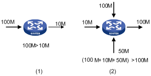
Congestion easily occurs in complex packet switching circumstances in the Internet, Figure 1 shows some common cases.
Figure 1 Traffic congestion causes
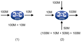
· The traffic enters a router from a high-speed link and is forwarded over a low-speed link.
· The packet flows enter a router from several interfaces and are forwarded out an interface, whose speed is smaller than the sum of the incoming interfaces.
When traffic arrives at the line speed, congestion may occur due to the network resource bottleneck.
Besides the link bandwidth bottleneck, congestion can also be caused by resource shortages (such as insufficient processor time, buffer, and memory). In addition, congestion may occur if the arriving traffic is not managed efficiently, thus resulting in inadequate network resources.
Impacts
Congestion can bring the following negative results:
· Increased delay and jitter during packet transmission
· Decreased network throughput and resource use efficiency
· Network resource (memory, in particular) exhaustion and even system breakdown
Congestion hinders resource assignment for traffic and degrades service performance. Congestion is unavoidable in switched networks and multi-user application environments. To improve the service performance of your network, you must address the congestion issues.
Countermeasures
A simple solution for congestion is to increase network bandwidth. However, this solution cannot solve all the problems that cause congestion because you cannot increase network bandwidth infinitely.
A more effective solution is to provide differentiated services for different applications through traffic control and resource allocation. In this way, resources can be used more properly. During resources allocation and traffic control, the direct or indirect factors that might cause network congestion must be controlled to reduce the probability of congestion. Once congestion occurs, resource allocation must be performed according to the characteristics and demands of applications to minimize the effects of congestion.
Major traffic management technologies
Figure 2 Positions of the QoS techniques in a network
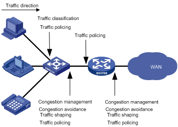
As shown in Figure 2, traffic classification, traffic shaping, traffic policing, congestion management, and congestion avoidance mainly implement the following functions:
· Traffic classification uses certain match criteria to assign packets with the same characteristics to a class. Based on classes, you can provide differentiated services.
· Traffic policing polices flows entering or leaving a device. You can apply traffic policing to both incoming and outgoing traffic of a port. When a flow exceeds the pre-set threshold, some restriction or punishment measures can be taken to prevent overconsumption of network resources.
· Traffic shaping proactively adapts the output rate of traffic to the network resources available on the downstream device to eliminate packet drop. Traffic shaping is usually applied to the outgoing traffic of a port.
· Congestion management provides a resource scheduling policy to arrange the forwarding sequence of packets when congestion occurs. Congestion management is usually applied to the outgoing traffic of a port.
· Congestion avoidance monitors the usage status of network resources and is usually applied to the outgoing traffic of a port. As congestion becomes worse, it actively reduces the queue length by dropping packets.
Traffic shaping overview
If user traffic is not limited, burst traffic will make the network more congested. Therefore it is necessary to limit user traffic to better utilize the network resources and provide better services for more users. For example, you can configure a flow to use only the resources committed to it in a certain time range, thus avoiding network congestion caused by burst traffic.
Generic traffic shaping (GTS) limits the traffic rate and resource use according to traffic specifications. The prerequisite for GTS is to know whether a traffic flow has exceeded the specification. If yes, proper traffic control policies are applied. Usually, token buckets evaluate traffic specifications.
Traffic evaluation and token bucket
Token bucket features
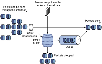
A token bucket is analogous to a container holding a certain number of tokens. The system puts tokens into the bucket at a set rate. When the token bucket is full, the extra tokens will cause the token bucket to overflow.
Figure 3 Evaluate traffic with the token bucket
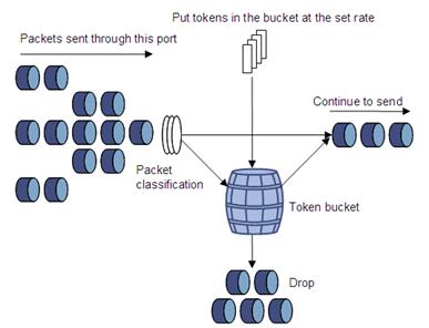
Evaluating traffic with the token bucket
The evaluation of traffic specifications is based on whether the number of tokens in the bucket is enough for forwarding the packets. Generally, one token is associated with a 1-bit forwarding authority. When a packet of n bits is forwarded, n tokens are taken out of the token bucket. If the number of tokens in the bucket is enough for forwarding the packets, the traffic conforms to the specification, and is called the “conforming traffic”. Otherwise, the traffic does not conform to the specification, and is called the “excess traffic”.
A token bucket has the following configurable parameters:
· Mean rate—Rate at which tokens are put into the bucket, or the permitted average rate of traffic. It is also called the “committed information rate (CIR)”.
· Burst size—Capacity of the token bucket, or the maximum traffic size that is permitted in each burst. It is also called the “committed burst size (CBS)”. The set burst size must be greater than the maximum packet size.
One evaluation is performed on each arriving packet. In each evaluation, if the number of tokens in the bucket is enough, the traffic conforms to the specification and the tokens for forwarding the packet are taken away; if the number of tokens in the bucket is not enough, it means that too many tokens have been used and the traffic is excessive.
Complicated evaluation
You can set two token buckets, bucket C and bucket E, to evaluate traffic in a more complicated environment and achieve more policing flexibility. For example, traffic policing uses the following parameters:
· CIR—Rate at which tokens are put into bucket C, that is, the average packet transmission or forwarding rate allowed by bucket C.
· CBS—Size of bucket C, that is, transient burst of traffic that bucket C can forward.
· Peak information rate (PIR)—Rate at which tokens are put into bucket E, that is, the average packet transmission or forwarding rate allowed by bucket E.
· Excess burst size (EBS)—Size of bucket E, that is, transient burst of traffic that bucket E can forward.
Figure 4 Two-bucket structure
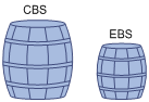
The two-bucket structure is as shown in Figure 4. CBS is implemented with bucket C and EBS with bucket E. In each evaluation, packets are measured against the following bucket scenarios:
· If bucket C has enough tokens, packets are colored green.
· If bucket C does not have enough tokens but bucket E has enough tokens, packets are colored yellow.
· If neither bucket C nor bucket E has sufficient tokens, packets are colored red.
Traffic policing
A typical application of traffic policing is to supervise the specification of certain traffic entering a network and limit it within a reasonable range, or to “discipline” the extra traffic to prevent aggressive use of network resources by a certain application. For example, you can limit bandwidth for HTTP packets to less than 50% of the total. If the traffic of a certain session exceeds the limit, traffic policing can drop the packets or reset the IP precedence of the packets.
Traffic policing is widely used in policing traffic into the networks of internet service providers (ISPs). It can classify the policed traffic and perform pre-defined policing actions based on different evaluation results. These actions include the following:
· Forwarding the packets whose evaluation result is “conforming”
· Dropping the packets whose evaluation result is “nonconforming”
· Modifying the IP precedence of the packets whose evaluation result is “conforming” and forwarding them
· Modifying the IP precedence of the packets whose evaluation result is “conforming” and delivering them into the next-level Traffic policing
Traffic shaping
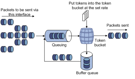
Traffic shaping limits the outbound traffic rate by buffering exceeding traffic. You can use traffic shaping to adapt the traffic output rate on a device to the input traffic rate of its connected device to avoid packet loss.
The difference between traffic policing and GTS is that packets to be dropped in traffic policing are cached in a buffer or queue in GTS, as shown in Figure 5. When the token bucket has enough tokens, these cached packets are sent at an even rate. Traffic shaping may result in an additional delay, but traffic policing does not.
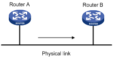
For example, in Figure 6, Router B performs traffic policing on packets from Router A and drops packets exceeding the limit. To avoid packet loss, you can perform traffic shaping on the outgoing interface of Router A so packets exceeding the limit are cached in Router A. Once resources are released, traffic shaping takes out the cached packets and sends them out.
Line rate
The line rate of a physical interface specifies the maximum rate for forwarding packets (including critical packets).
Line rate also uses token buckets for traffic control. With line rate configured on an interface, all packets to be sent through the interface are first handled by the token bucket at line rate. If the token bucket has enough tokens, packets can be forwarded. Otherwise, packets are put into QoS queues for congestion management. In this way, the traffic passing the physical interface is controlled.
Figure 7 Line rate implementation
The token bucket mechanism limits traffic rate and accommodates bursts. It allows bursty traffic to be transmitted as long as enough tokens are available. If tokens are inadequate, packets cannot be transmitted until efficient tokens are generated in the token bucket. It restricts the traffic rate to the rate for generating tokens.
Line rate limits the total rate of all packets on a physical interface. It is easier to use than traffic policing in controlling the total traffic rate on a physical interface.
Traffic shaping configuration
Configuring traffic shaping
Traffic shaping supports queue-based GTS, which configures GTS parameters for packets of a certain queue.
To configure queue-based GTS:
|
Step |
Command |
Remarks |
|
1. Enter system view. |
system-view |
N/A |
|
2. Enter interface view or port group view. |
· Enter interface view: · Enter port group view: |
Use either command. Settings in interface view are effective on the current interface. Settings in port group view are effective on all ports in the port group. |
|
3. Configure GTS for the interface or port group. |
qos gts queue queue-number cir committed-information-rate [ cbs committed-burst-size ] |
CBS is the traffic transmitted at the rate of CIR in 500 ms by default. The command is not available on low-speed CPOS interfaces. |
|
4. Display GTS configuration information. |
display qos gts interface [ interface-type interface-number ] [ | { begin | exclude | include } regular-expression ] |
Optional. Available in any view |
Configuring GTS for all traffic
To configure GTS for all traffic:
|
Step |
Command |
Remarks |
|
1. Enter system view. |
system-view |
N/A |
|
2. Enter interface view or port group view. |
· Enter interface view: · Enter port group view: |
Use either command. Settings in interface view are effective on the current interface. Settings in port group view are effective on all ports in the port group. |
|
3. Configure GTS on the interface or port group. |
qos gts any cir committed-information-rate [ cbs committed-burst-size ] |
For interfaces except low-speed CPOS interfaces, CBS is the traffic transmitted at the rate of CIR in 500 ms by default. For low-speed CPOS interfaces, CBS is 1024 bytes by default. |
|
4. Display GTS configuration information. |
display qos gts interface [ interface-type interface-number ] [ | { begin | exclude | include } regular-expression ] |
Optional. Available in any view |
|
|
NOTE: · Do not configure a CIR exceeding the interface bandwidth. Otherwise, the configuration will fail. · Do not configure the qos lr command and the qos gts any command on the same interface or port group at the same time. |
Displaying and maintaining GTS
|
Task |
Command |
Remarks |
|
Display interface GTS configuration information. |
display qos gts interface [ interface-type interface-number ] [ | { begin | exclude | include } regular-expression ] |
Available in any view |
Traffic shaping configuration example
Network requirements
Configure GTS on queue 0 of GigabitEthernet 3/1/2 of the router to shape the traffic at rates higher than 480 kbps.
Configuration procedure
# Enter system view.
<Sysname> system-view
# Enter interface view.
[Sysname] interface GigabitEthernet 3/1/2
# Configure the GTS parameter.
[Sysname-GigabitEthernet3/1/2] qos gts queue 0 cir 480
Line rate configuration
Configuring the line rate
The line rate of a physical interface specifies the maximum rate of outgoing packets.
To configure the line rate:
|
Step |
Command |
Remarks |
|
1. Enter system view. |
system-view |
N/A |
|
2. Enter interface view, port group view, or subinterface view. |
· Enter interface view: · Enter port group view: · Enter subinterface view: |
Use either command. Settings in interface view take effect on the current interface. Settings in port group view take effect on all ports in the port group. Settings in subinterface view take effect on the current subinterface. |
|
3. Configure the line rate for the interface or port group. |
qos lr outbound cir committed-information-rate [ cbs committed-burst-size ] |
By default, the CBS is the traffic transmitted at the rate of CIR in 500 ms. |
|
|
NOTE: · Do not configure a CIR exceeding the interface bandwidth. Otherwise, the configuration will fail. · The qos lr command is available for the interfaces on the subcards PIC-GP10L, PIC-GP20R, and PIC-GT20R. · The first time you configure the qos lr, queue ef bandwidth, queue af bandwidth, queue wfq, or remark local-precedence command for a subinterface, you must use the undo qos lr command to disable line rate on the main interface if none of these commands is configured on any other subinterfaces. · Do not configure the qos lr command and the qos gts any command on the same interface or port group at the same time. |
Displaying and maintaining line rate
|
Task |
Command |
Remarks |
|
Display interface line rate configuration information. |
display qos lr interface [ interface-type interface-number ] [ | { begin | exclude | include } regular-expression ] |
Available in any view |
Line rate configuration example
1. Network requirements
Configure line rate on interface GigabitEthernet 3/1/2 to limit the rate of outgoing packets to 480 kbps.
2. Configuration procedure
# Enter system view.
<Sysname> system-view
# Enter interface view.
[Sysname] interface GigabitEthernet 3/1/2
# Configure line rate on the interface.
[Sysname-GigabitEthernet3/1/2] qos lr outbound cir 480
QoS policy overview
A QoS policy involves three components: class, traffic behavior, and policy. You can associate a class with a traffic behavior using a QoS policy.
Class
Classes identify traffic.
A class is identified by a class name and contains some match criteria.
You can define a set of match criteria to classify packets, and the relationship between criteria can be one of the following:
· and—The router considers that a packet belongs to a class only when the packet matches all the criteria in the class.
· or—The router considers that a packet belongs to a class as long as the packet matches one of the criteria in the class.
Traffic behavior
A traffic behavior, identified by a name, defines a set of QoS actions for packets.
Policy
A policy associates a class with a traffic behavior.
You can configure multiple class-to-traffic behavior associations in a policy.
Traffic classification overview
Traffic classification
When defining match criteria for classifying traffic, you can use IP precedence bits in the type of service (ToS) field of the IP packet header, or other header information such as IP addresses, MAC addresses, IP protocol field, and port numbers. You can define a class for packets with the same quintuple (source address, source port number, protocol number, destination address, and destination port number for example), or for all packets to a certain network segment.
When packets are classified on the network boundary, the precedence bits in the ToS field of the IP packet header are usually reset. In this way, IP precedence can be directly used to classify the packets in the network. IP precedence can also be used in queuing to prioritize traffic. The downstream network can either use the classification results from its upstream network or classify the packets again according to its own criteria.
To provide differentiated services, traffic classes must be associated with certain traffic control actions or resource allocation actions. What traffic control actions to use depends on the current phase and the resources of the network. For example, CAR polices packets when they enter the network, GTS is performed on packets when they leave the node, queue scheduling is performed when congestion happens, and congestion avoidance measures are taken when the congestion deteriorates.
Packet precedences
This section introduces IP precedence, ToS precedence, differentiated services codepoint (DSCP) values, 802.1p priority, and EXP values.
1. IP precedence, ToS precedence, and DSCP values
Figure 8 DS field and ToS bytes
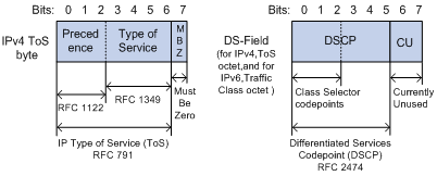
As shown in Figure 8, the ToS field in the IP header contains eight bits: the first three bits (0 to 2) represent IP precedence from 0 to 7; the subsequent four bits (3 to 6) represent a ToS value from 0 to 15. According to RFC 2474, the ToS field is redefined as the differentiated services (DS) field, where a DSCP value is represented by the first six bits (0 to 5) and ranges from 0 to 63. The remaining two bits (6 and 7) are reserved.
Table 1 Description on IP Precedence
|
IP precedence (decimal) |
IP precedence (binary) |
Description |
|
0 |
000 |
Routine |
|
1 |
001 |
priority |
|
2 |
010 |
immediate |
|
3 |
011 |
flash |
|
4 |
100 |
flash-override |
|
5 |
101 |
critical |
|
6 |
110 |
internet |
|
7 |
111 |
network |
In a network in the Diff-Serve model, traffic is grouped into the following classes, and packets are processed according to their DSCP values:
· Expedited forwarding (EF) class—In this class, packets are forwarded regardless of link share of other traffic. The class is suitable for preferential services requiring low delay, low packet loss, low jitter, and high bandwidth.
· Assured forwarding (AF) class—This class is divided into four subclasses (AF 1 to AF 4), each containing three drop priorities for more granular classification. The QoS level of the AF class is lower than that of the EF class.
· Class selector (CS) class—This class is derived from the IP ToS field and includes eight subclasses.
· Best effort (BE) class—This class is a special CS class that does not provide any assurance. AF traffic exceeding the limit is degraded to the BE class. All IP network traffic belongs to this class by default.
Table 2 Description on DSCP values
|
DSCP value (decimal) |
DSCP value (binary) |
Description |
|
46 |
101110 |
ef |
|
10 |
001010 |
af11 |
|
12 |
001100 |
af12 |
|
14 |
001110 |
af13 |
|
18 |
010010 |
af21 |
|
20 |
010100 |
af22 |
|
22 |
010110 |
af23 |
|
26 |
011010 |
af31 |
|
28 |
011100 |
af32 |
|
30 |
011110 |
af33 |
|
34 |
100010 |
af41 |
|
36 |
100100 |
af42 |
|
38 |
100110 |
af43 |
|
8 |
001000 |
cs1 |
|
16 |
010000 |
cs2 |
|
24 |
011000 |
cs3 |
|
32 |
100000 |
cs4 |
|
40 |
101000 |
cs5 |
|
48 |
110000 |
cs6 |
|
56 |
111000 |
cs7 |
|
0 |
000000 |
be (default) |
2. 802.1p priority
802.1p priority lies in Layer 2 packet headers and is applicable to occasions where Layer 3 header analysis is not needed and QoS must be assured at Layer 2.
Figure 9 An Ethernet frame with an 802.1Q tag header
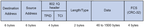
As shown in Figure 9, the 4-byte 802.1Q tag header consists of the tag protocol identifier (TPID, two bytes in length), whose value is 0x8100, and the tag control information (TCI, two bytes in length). Figure 10 presents the format of the 802.1Q tag header.
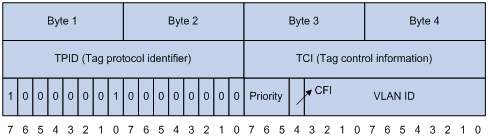
The priority in the 802.1Q tag header is called 802.1p priority, because its use is defined in IEEE 802.1p. Table 3 presents the values for 802.1p priority.
Table 3 Description on 802.1p priority
|
802.1p priority (decimal) |
802.1p priority (binary) |
Description |
|
0 |
000 |
best-effort |
|
1 |
001 |
background |
|
2 |
010 |
spare |
|
3 |
011 |
excellent-effort |
|
4 |
100 |
controlled-load |
|
5 |
101 |
video |
|
6 |
110 |
voice |
|
7 |
111 |
network-management |
3. EXP values
The EXP field lies in MPLS labels for QoS purposes.
Figure 11 MPLS label structure
![]()
As shown in Figure 11, the EXP field is 3 bits long and ranges from 0 to 7.
QoS policy configuration procedure
To configure a QoS policy:
1. Create a class and define a set of match criteria in class view.
2. Create a traffic behavior and define a set of QoS actions in traffic behavior view.
3. Create a policy and associate the traffic behavior with the class in policy view.
4. Apply the QoS policy.
Defining a class
To define a class, specify its name and then configure the match criteria in class view.
Configuration procedure
To define a class:
|
Step |
Command |
Remarks |
|
1. Enter system view. |
system-view |
N/A |
|
2. Create a class and enter class view. |
traffic classifier tcl-name [ operator { and | or } ] |
By default, the operator of a class is logic and. |
|
3. Configure match criteria. |
if-match match-criteria |
N/A |
|
4. Display class information. |
display traffic classifier user-defined [ tcl-name ] [ | { begin | exclude | include } regular-expression ] |
Optional. Available in any view |
Configuration example
1. Network requirements
Configure a class named test_class. Packets with the destination MAC address 0050-BA27-BED3 belong to the class.
2. Configuration procedure
# Enter system view.
<Sysname> system-view
# Define a class and enter class view.
[Sysname] traffic classifier test_class
# Define a match criterion.
[Sysname-classifier-test_class] if-match destination-mac 0050-ba27-bed3
Defining a traffic behavior
A traffic behavior is a set of QoS actions (such as traffic filtering, shaping, policing, and priority marking) to take on a class of traffic. To define a traffic behavior, first create it and then configure QoS actions (such as priority marking and traffic redirecting) in traffic behavior view.
Configuration procedure
To define a traffic behavior:
|
Step |
Command |
Remarks |
|
1. Enter system view. |
system-view |
N/A |
|
2. Create a traffic behavior and enter traffic behavior view. |
traffic behavior behavior-name |
N/A |
|
3. Enable traffic accounting. |
accounting [ byte | packet ] |
N/A You can configure the traffic behavior as required. |
|
4. Configure a CAR action. |
car cir committed-information-rate [ cbs committed-burst-size [ ebs excess-burst-size ] ] [ pir peak-information-rate ] [ red { discard | pass } ] |
|
|
5. Drop or send packets. |
filter { deny | permit } |
|
|
6. Redirect traffic to a specified target. |
redirect { cpu | next-hop { ipv4-add [ track track-entry-number ] [ ipv4-add [ track track-entry-number ] ] | ipv6-add [ interface-type interface-number ] [ track track-entry-number ] [ ipv6-add [ interface-type interface-number ] [ track track-entry-number ] ] } [ fail-action { discard | forward } ] | vpn-instance vpn-instance-name } |
|
|
7. Set the DSCP value for packets. |
remark dscp dscp-value |
|
|
8. Set the 802.1p priority for packets. |
remark dot1p 8021p |
|
|
9. Set the drop precedence for packets. |
remark drop-precedence drop-precedence-value |
|
|
10. Set the IP precedence for packets. |
remark ip-precedence ip-precedence-value |
|
|
11. Set the local precedence for packets. |
remark local-precedence local-precedence |
|
|
12. Set the EXP value for MPLS packets. |
remark mpls-exp exp-value |
|
|
13. Assign priority values to packets using a specified priority mapping table. |
primap { pre-defined { color { up-dot1p | up-dscp | up-exp | up-lp } | dscp-dscp } | color-map-dp } |
|
|
14. Configure the default traffic redirecting action. |
redirect-default next-hop ipv4-add1 [ track track-entry-number ] [ ipv4-add2 [ track track-entry-number ] ] |
|
|
15. Display traffic behavior configuration information. |
display traffic behavior user-defined [ behavior-name ] [ | { begin | exclude | include } regular-expression ] |
Optional. Available in any view |
|
|
NOTE: · The priority mapping table to be included in the primap pre-defined command must be configured beforehand. For more information, see the chapter “Configuring priority mapping.” · For an ordinary port in an isolation group, only the following commands take effect on its incoming traffic: accounting, filter deny, car cir committed-information-rate red discard, and mirror-to. · In a traffic behavior, redirecting traffic to the CPU, redirecting traffic to the next hop, and redirecting traffic to a VPN-instance cannot co-exist and the one configured the last overwrites the previous one. |
Defining a policy
In a policy, you can define multiple class-behavior associations, and these associations are matched in the order they are configured. A behavior is performed for an associated class of packets. In this way, various QoS features can be implemented.
To define a policy:
|
Step |
Command |
Remarks |
|
1. Enter system view. |
system-view |
N/A |
|
2. Create a policy and enter policy view. |
qos policy policy-name |
N/A |
|
3. Associate a class with a behavior in the policy. |
classifier tcl-name behavior behavior-name |
N/A |
|
4. Display the information about a QoS policy information or a traffic behavior associated with a QoS policy. |
display qos policy user-defined [ policy-name [ classifier tcl-name ] ] [ | { begin | exclude | include } regular-expression ] |
Optional. Available in any view |
Applying the QoS policy
You can apply the QoS policy in different views.
You can apply a QoS policy to the following destinations:
· An interface—The policy takes effect on the traffic sent or received on the interface.
· A VLAN—The policy takes effect on the traffic sent or received on all ports in the VLAN.
· Globally—The policy takes effect on the traffic sent or received on all ports.
You can modify the match criteria, traffic behaviors, and classifier-behavior associations of a QoS policy already applied. If a class in the QoS policy uses an ACL as a match criterion, you can modify or delete the ACL, for example, add, delete, and modify the ACL rules.
|
|
NOTE: VLANs do not support user-defined flow templates. In case an interface referencing a user-defined flow template and a VLAN on the interface have been each associated with a module QoS command (MQC) policy in the same direction, the one on the interface takes effect and the one on the VLAN do not take effect. |
Applying the QoS policy to an interface
A policy can be applied to multiple interfaces. Only one policy can be applied in one direction (inbound or outbound) of an interface.
To apply a policy to an interface:
|
Step |
Command |
Remarks |
|
1. Enter system view. |
system-view |
N/A |
|
2. Enter interface view or port group view. |
· Enter interface view: · Enter port group view: |
Use either command. Settings in interface view are effective on the current interface. Settings in port group view are effective on all ports in the port group. |
|
3. Apply a policy to the interface or port group. |
qos apply policy policy-name { inbound | outbound } |
N/A |
|
|
NOTE: · You can apply QoS policies to all physical interfaces except interfaces configured with X.25 or LAPB. · The QoS policy applied to the outgoing traffic on an interface does not regulate local packets. Local packets refer to the critical protocol packets sent by the local system for maintaining the normal operation of the router. To avoid drop of local packets, QoS does not process them. Commonly used local packets include link maintenance packets, IS-IS packets, OSPF packets, RIP packets, BGP packets, LDP packets, RSVP packets, and SSH packets. |
Applying the QoS policy to a VLAN
To apply the QoS policy to a VLAN:
|
Step |
Command |
|
1. Enter system view. |
system-view |
|
2. Apply the QoS policy to one or multiple VLANs. |
qos vlan-policy policy-name vlan vlan-id-list { inbound | outbound } |
|
|
NOTE: You cannot apply QoS policies to dynamic VLANs, for example, VLANs created by GVRP. |
Applying the QoS policy globally
You can apply a QoS policy globally to the inbound or outbound direction of all ports.
To apply the QoS policy globally:
|
Step |
Command |
|
1. Enter system view. |
system-view |
|
2. Apply the QoS policy globally. |
qos apply policy policy-name global { inbound | outbound } |
|
|
NOTE: · If the hardware resources of an interface card are insufficient, applying a QoS policy globally may fail on the interface card. The system does not automatically roll back the QoS policy configuration already applied to the main processing unit or other interface cards. To ensure consistency, you must use the undo qos apply policy global command to manually remove the QoS policy configuration applied to them. · The qos apply policy global command is available only on the SPC cards. |
QoS policy configuration example
1. Network requirements
Configure a QoS policy named test_policy. Associate the traffic behavior test_behavior with the traffic class test_class in the policy, and apply the policy to the following occasions:
¡ The incoming traffic of GigabitEthernet 2/1/1
¡ The incoming traffic of VLANs 200, 300, 400, 500, 600, 700, 800, and 900
2. Configuration procedure
# Create a QoS policy test_policy.
<Sysname> system-view
[Sysname] qos policy test_policy
[Sysname-qospolicy-test_policy] classifier test_class behavior test_behavior
[Sysname-qospolicy-test_policy] quit
# Apply the QoS policy test_policy to the incoming traffic of GigabitEthernet 2/1/1.
[Sysname] interface GigabitEthernet2/1/1
[Sysname-GigabitEthernet2/1/1] qos apply policy test_policy inbound
[Sysname-GigabitEthernet2/1/1] quit
# Apply the QoS policy test_policy to the incoming traffic of the specified VLANs.
[Sysname] qos vlan-policy test_policy vlan 200 300 400 500 600 700 800 900 inbound
Displaying and maintaining QoS policies
|
Task |
Command |
Remarks |
|
Display the configuration information of the specified class or all the classes and associated behaviors in the specified policy or all policies. |
display qos policy user-defined [ policy-name [ classifier tcl-name ] ] [ | { begin | exclude | include } regular-expression ] |
Available in any view |
|
Display QoS policy configuration information of the specified interface or all interfaces. |
display qos policy interface [ interface-type interface-number ] [ inbound | outbound ] [ | { begin | exclude | include } regular-expression ] |
Available in any view |
|
Display traffic behavior configuration information. |
display traffic behavior user-defined [ behavior-name ] [ | { begin | exclude | include } regular-expression ] |
Available in any view |
|
Display traffic class information. |
display traffic classifier user-defined [ tcl-name ] [ | { begin | exclude | include } regular-expression ] |
Available in any view |
|
Display VLAN QoS policy information. |
display qos vlan-policy { name policy-name | vlan [ vlan-id ] } [ slot slot-number ] [ inbound | outbound ] [ | { begin | exclude | include } regular-expression ] |
Available in any view |
|
Clear VLAN QoS policy statistics. |
reset qos vlan-policy [ vlan vlan-id ] [ inbound | outbound ] |
Available in user view |
Congestion management overview
Causes, impacts, and countermeasures of congestion
Congestion occurs on a link or node when traffic size exceeds the processing capability of the link or node. It is typical of a statistical multiplexing network and can be caused by link failures, insufficient resources, and various other causes. Figure 12 shows some common congestion scenarios.
Figure 12 Traffic congestion causes
Congestion can bring the following negative results:
· Increased delay and jitter during packet transmission
· Decreased network throughput and resource use efficiency
· Network resource (memory in particular) exhaustion and even system breakdown
Congestion is unavoidable in switched networks or multi-user application environments. To improve the service performance of your network, you must take measures to manage and control it.
One major issue that congestion management deals with is how to define a resource dispatching policy to prioritize packets for forwarding when congestion occurs.
Congestion management policies
Queuing is a common congestion management technique. It classifies traffic into queues and picks out packets from each queue by using a certain algorithm. Various queuing algorithms are available, each addressing a particular network traffic problem. Your choice of algorithm affects bandwidth assignment, delay, and jitter significantly.
Congestion management involves queue creating, traffic classification, packet enqueuing, and queue scheduling. Queue scheduling treats packets with different priorities differently to transmit high-priority packets preferentially.
Several common queue-scheduling mechanisms are introduced here.
Weighted fair queuing
|
|
NOTE: WFQ is applicable to only SPE cards. |
Figure 13 Weighted fair queuing (WFQ)
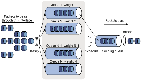
WFQ is an enhancement to fair queuing (FQ). FQ is designed for fairly sharing network resources, reducing delay and jitter of traffic. To this end, FQ takes many aspects into consideration to guarantee fairness among different queues and packets of different sizes during scheduling to
· Prevent packets in low-priority queues from being starved.
· Minimize jitter between packets in each stream by preferentially scheduling short packets in case both large packets and short packets are waiting in the queues.
Compared with FQ, WFQ takes weights into account when determining the queue scheduling order. Statistically, WFQ gives high priority traffic more scheduling opportunities than low priority traffic. When dequeuing packets, WFQ assigns the outgoing interface bandwidth to each traffic flow by precedence. The higher precedence a traffic flow has, the more bandwidth it gets.
For example, assume that three flows exist on the current interface, with the precedence 1, 2, and 3 respectively. The total bandwidth quota is 6, that is, the sum of all the precedence values. The bandwidth percentage assigned to each flow is (precedence value of the flow)/total bandwidth quota. Thus, the bandwidth percentages for the flows are 1/6, 2/6, and 3/6 respectively.
Hardware WFQ provides multiple queues, each with its individual weight.
|
|
NOTE: Queue 0 is a BE queue, queues 1 through 4 are AF queues, queue 5 and queue 6 are EF queues, and queue 7 is a NC queue. Different types of queues are scheduled by SP, and queues of the same type are scheduled based on their weights. |
CBQ
Class-based queuing (CBQ) extends WFQ by supporting user-defined classes. CBQ assigns an independent reserved FIFO queue for each user-defined class to buffer data of the class. When network congestion occurs, CBQ enqueues packets by user-defined match criteria. Before that, congestion avoidance actions such as tail drop or weighted random early detection (WRED) and bandwidth restriction check are performed before packets are enqueued. When being dequeued, packets are scheduled by WFQ.
CBQ provides an emergency queue to enqueue emergent packets. The emergency queue is a FIFO queue without bandwidth restriction. However, delay sensitive flows like voice packets may not be transmitted timely in CBQ since packets are fairly treated. To solve this issue, Low Latency Queuing (LLQ) was introduced to combine PQ and CBQ to transmit delay sensitive flows like voice packets preferentially.
When defining traffic classes for LLQ, you can configure a class of packets to be transmitted preferentially. Such a class is called a priority class. The packets of all priority classes are assigned to the same priority queue. Bandwidth restriction on each class of packets is checked before the packets are enqueued. During the dequeuing operation, packets in the priority queue are transmitted first. WFQ dequeues packets in the other queues.
In order to reduce the delay of the other queues except the priority queue, LLQ assigns the maximum available bandwidth for each priority class. The bandwidth value polices traffic during congestion. When no congestion is present, a priority class can use more than the bandwidth assigned to it. During congestion, the packets of each priority class exceeding the assigned bandwidth are discarded. LLQ can also specify burst-size.
In a QoS policy, the class-behavior associations take effect in the order they are configured, and the one configured first takes effect first. Similarly, the match criteria configured in a class take effect in the order they are configured, and the one configured first takes effect first. Therefore, when you configure a QoS policy, configure the class-behavior associations in the order of EF, AF, and BE.
Configuring WFQ queuing
Configuration procedure
To configure basic WFQ queuing:
|
Step |
Command |
Remarks |
|
1. Enter system view. |
system-view |
N/A |
|
2. Enter interface view or port group view. |
· Enter interface view: · Enter port group view: |
Use either command. Settings in interface view are effective on the current interface. Settings in port group view are effective on all ports in the port group. |
|
3. Set the scheduling weight for a basic WFQ queue. |
qos wfq queue weight schedule-value |
Repeat this step to configure other queues as required. |
|
4. Configure the minimum guaranteed bandwidth for a WFQ queue. |
qos bandwidth queue queue-number min bandwidth-value |
Optional. The value for the bandwidth-value argument cannot exceed the interface bandwidth. Repeat this step to configure other queues as required. |
|
5. Display WFQ queuing configuration on interfaces. |
display qos wfq interface [ interface-type interface-number ] [ | { begin | exclude | include } regular-expression ] |
Optional. Available in any view |
Configuration example
Network requirements
Configure the weights of queue 2, queue 3, and queue 4 as 5, 10, and 20, respectively.
Configuration procedure
# Enter system view.
<Sysname> system-view
# Configure WFQ queuing on GigabitEthernet 2/1/1.
[Sysname] interface GigabitEthernet 2/1/1
[Sysname-GigabitEthernet2/1/1] qos wfq 2 weight 5
[Sysname-GigabitEthernet2/1/1] qos wfq 3 weight 10
[Sysname-GigabitEthernet2/1/1] qos wfq 4 weight 20
Configuring CBQ
To configured CBQ:
1. Create a class and define a set of traffic match criteria in class view.
2. Create a traffic behavior, and define a group of QoS features in traffic behavior view.
3. Create a policy, and associate a traffic behavior with a class in policy view.
4. Apply the QoS policy to the outgoing traffic of an interface.
Defining a class
For how to define a class, see the chapter “Configuring a QoS policy.”
|
|
NOTE: To make sure that the traffic not entering the EF and AF queues enters the BE queue (the default priority queue), you must configure a default class that permits any traffic, and use the default class in the last class-behavior association of the QoS policy. |
Defining a traffic behavior
To define a traffic behavior, you should first create the traffic behavior with a name specified and then configure attributes for it in traffic behavior view.
Configure AF and the guaranteed bandwidth
To configure AF and the guaranteed bandwidth:
|
Step |
Command |
|
1. Enter system view. |
system-view |
|
2. Create a traffic behavior and enter traffic behavior view. |
traffic behavior behavior-name |
|
3. Configure AF and the guaranteed bandwidth. |
queue af bandwidth bandwidth |
|
|
NOTE: · You cannot configure the queue af command together with the queue ef or queue wfq command in the same traffic behavior. · You can apply this traffic behavior only to the outgoing traffic of an interface. · The guaranteed bandwidth specifies the bandwidth that is guaranteed for the AF traffic, regardless of congestion on the interface. The AF traffic exceeding the guaranteed bandwidth and the BE traffic compete for bandwidth. The forwarding for the exceeding AF traffic depends on the congestion conditions on the interface. |
Configuring EF and the guaranteed bandwidth
To configure EF and the guaranteed bandwidth:
|
Step |
Command |
|
1. Enter system view. |
system-view |
|
2. Create a traffic behavior and enter traffic behavior view. |
traffic behavior behavior-name |
|
3. Configure EF and the guaranteed bandwidth. |
queue ef bandwidth bandwidth [ cbs burst ] |
|
|
NOTE: · You cannot configure the queue ef command together with any of the commands queue af, queue wfq, and wred in the same traffic behavior. · You can apply this behavior only to the outgoing traffic of an interface. · The bandwidth argument ranges from 64 to 10000000 in kbps. The burst argument ranges from 1600 to 1000000000 in bytes. If the burst argument is not configured, it is 25 times of the bandwidth argument. · The guaranteed bandwidth specifies the bandwidth that is guaranteed for the EF traffic, regardless of congestion on the interface. The forwarding for the EF traffic exceeding the guaranteed bandwidth depends on the congestion conditions on the interface. |
Configuring WFQ
To configure WFQ:
|
Step |
Command |
|
1. Enter system view. |
system-view |
|
2. Create a traffic behavior and enter traffic behavior view. |
traffic behavior behavior-name |
|
3. Configure WFQ. |
queue wfq |
Using WRED drop
To use WRED drop:
|
Step |
Command |
Remarks |
|
1. Enter system view. |
system-view |
N/A |
|
2. Create a traffic behavior and enter traffic behavior view. |
traffic behavior behavior-name |
N/A |
|
3. Use WRED drop. |
wred [ dscp | ip-precedence ] |
· dscp: Uses the DSCP value for calculating the drop probability for a packet. · ip-precedence: Uses the IP precedence value for calculating the drop probability for a packet. This keyword is used by default. |
|
|
NOTE: · You cannot configure the wred command together with the queue ef command in the same traffic behavior. · Before configuring the wred [ dscp | ip-precedence ] command, make sure that you have configured the queue af or queue wfq command. · You can apply this behavior to only the outgoing traffic of an interface. |
Defining a QoS policy
For how to define a QoS policy, see the chapter “Configuring a QoS policy.”
Applying the QoS policy
Use the qos apply policy command to apply a policy to a specific physical interface or subinterface. A policy can be applied to multiple physical interfaces.
To apply a policy to the specific interface:
|
Step |
Command |
Remarks |
|
1. Enter system view. |
system-view |
N/A |
|
2. Enter interface view or port group view. |
· Enter interface view: · Enter port group view: |
Use either command. Settings in interface view are effective on the current interface. Settings in port group view are effective on all ports in the port group. |
|
3. Apply a policy to the interface. |
qos apply policy policy-name { inbound | outbound } |
N/A |
|
|
NOTE: · Depending on the match criteria configured in classes of a QoS policy, you may need to apply a flow template to an interface before applying the QoS policy to the interface. · You can apply a QoS policy containing a CBQ action only to the outgoing traffic of an interface. · The QoS policy applied to the outgoing traffic on an interface does not regulate local packets. Local packets refer to the critical protocol packets sent by the local system for maintaining the normal operation of the router. To avoid drop of local packets, QoS does not process them. Commonly used local packets include link maintenance packets, IS-IS packets, OSPF packets, RIP packets, BGP packets, LDP packets, RSVP packets, and SSH packets. · An RPR interface does not support CBQ. · You can apply a QoS policy containing a CBQ action only to an interface. · To apply a QoS policy to an ATM interface, configure the ATM interface as the P2P type. · To guarantee that a QoS policy containing a CBQ action works properly, do not configure a GTS action or any of the queuing features (queue ef, queue af, and queue wfq) in the QoS policy. · Frame relay traffic shaping (FRTS) on an MFR interface may affect the operation of CBQ. Therefore, do not configure a FRTS action together with a CBQ action in a QoS policy applied to an MFR interface. · You cannot apply a QoS policy containing a CBQ action to an HQoS-configured interface. You cannot configure HQoS on an interface configured with a QoS policy containing a CBQ action. · In a QoS policy, make sure that the sum of bandwidth assigned to EF queues, AF queues, and BE queues does not exceed the actual bandwidth of the target interface. Otherwise, CBQ does not work as expected. |
Displaying and maintaining CBQ
For how to display and maintain CBQ, see the chapter “Configuring a QoS policy.”
CBQ configuration example
Network requirements
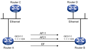
As shown in Figure 14, traffic travels from Router C to Router D through Router A and Router B.
Configure a QoS policy to meet the following requirements:
· Traffic from Router C is classified into three classes based on DSCP values; perform AF for traffic with the DSCP values AF11 and AF21 and set the guaranteed bandwidth to 5 Mbps.
· Perform EF for traffic with the DSCP value EF and set the guaranteed bandwidth to 30 Mbps.
Before performing the configuration, make sure that:
· Router C can reach Router D through Router A and Router B.
· The DSCP fields have been set for the traffic before the traffic enters Router A.
Configuration procedure
Configure Router A
# Define three classes to match the IP packets with the DSCP values AF11, AF21 and EF respectively.
<RouterA> system-view
[RouterA] traffic classifier ef_class
[RouterA-classifier-ef_class] if-match dscp ef
[RouterA-classifier-ef_class] quit
[RouterA] traffic classifier af11_class
[RouterA-classifier-af11_class] if-match dscp af11
[RouterA-classifier-af11_class] quit
[RouterA]traffic classifier af21_class
[RouterA-classifier-af21_class] if-match dscp af21
[RouterA-classifier-af21_class] quit
# Define a default class named be_class to match all IP packets.
[RouterA] acl number 3000
[RouterA] rule 0 permit ip
[RouterA] traffic classifier be_class
[RouterA-classifier-be_class] if-match acl 3000
[RouterA-classifier-be_class] quit
# Define a traffic behavior named ef_behav, configure EF in the behavior, and set the guaranteed bandwidth to 30720 kbps.
[RouterA] traffic behavior ef_behav
[RouterA-behavior-ef_behav] queue ef bandwidth 30720
[RouterA-behavior-ef_behav] quit
# Define a traffic behavior af11_behav, configure AF in the traffic behavior, and set the guaranteed bandwidth to 5120 kbps. Configure traffic behavior af21_behav in a similar way.
[RouterA] traffic behavior af11_behav
[RouterA-behavior-af11_behav] queue af bandwidth 5120
[RouterA-behavior-af11_behav] quit
[RouterA] traffic behavior af21_behav
[RouterA-behavior-af21_behav] queue af bandwidth 5120
[RouterA-behavior-af21_behav] quit
# Define a traffic behavior named be_behav, configure WFQ in the traffic behavior, and configure the drop mode as WRED.
[RouterA] traffic behavior be_behav
[RouterA-behavior-be_behav] queue wfq
[RouterA-behavior-be_behav] wred
[RouterA-behavior-be_behav] quit
# Create a QoS policy named dscp, and associate the defined classes with the behaviors as needed.
[RouterA] qos policy dscp
[RouterA-qospolicy-dscp] classifier ef_class behavior ef_behav
[RouterA-qospolicy-dscp] classifier af11_class behavior af11_behav
[RouterA-qospolicy-dscp] classifier af21_class behavior af21_behav
[RouterA-qospolicy-dscp] classifier be_class behavior be_behav
[RouterA-qospolicy-dscp] quit
# Apply QoS policy dscp to the outgoing traffic of interface GigabitEthernet 3/1/1.
[RouterA-GigabitEthernet3/1/1] qos apply policy dscp outbound
[RouterA-GigabitEthernet3/1/1] quit
# After the configuration, display the QoS policy configuration on interface GigabitEthernet 3/1/1 to verify the configuration.
[RouterA] display qos policy interface GigabitEthernet 3/1/1 outbound
Interface: GigabitEthernet3/1/1
Direction: Outbound
Policy: dscp
Classifier: ef_class
Operator: AND
Rule(s) : If-match dscp ef
Behavior: ef_behav
Expedited Forwarding:
Bandwidth 30720 (Kbps), CBS 768000 (Bytes)
Matched : 100/6400 (Packets/Bytes)
Enqueued : 100/6400 (Packets/Bytes)
Discarded: 0/0 (Packets/Bytes)
Classifier: af11_class
Operator: AND
Rule(s) : If-match dscp af11
Behavior: af11_behav
Assured Forwarding:
Bandwidth 5120 (Kbps)
Matched : 50/3200 (Packets/Bytes)
Enqueued : 50/3200 (Packets/Bytes)
Discarded: 0/0 (Packets/Bytes)
Classifier: af21_class
Operator: AND
Rule(s) : If-match dscp af21
Behavior: af21_behav
Assured Forwarding:
Bandwidth 5120 (Kbps)
Matched : 50/3200 (Packets/Bytes)
Enqueued : 50/3200 (Packets/Bytes)
Discarded: 0/0 (Packets/Bytes)
Classifier: be_class
Operator: AND
Rule(s) : If-match acl 3000
Behavior: be_behav
Flow Based Weighted Fair Queuing
Matched : 1000/128000 (Packets/Bytes)
Discard Method: IP Precedence based WRED
Priority mapping overview
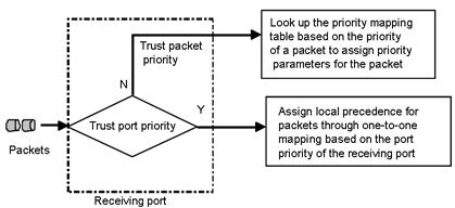
When a packet enters a router, the router assigns a set of QoS priority parameters to the packet based on a certain priority field carried in the packet or the port priority of the incoming port, depending on your configuration. This process is called priority mapping. During this process, the router may modify the priority of the packet depending on router status. The set of QoS priority parameters decides the scheduling priority and forwarding priority of the packet.
Priority mapping is implemented with priority mapping tables and involves priorities such as 802.11e priority, 802.1p priority, DSCP, EXP, IP precedence, local precedence, and drop precedence.
The local precedence and drop precedence are defined as follows:
· Local precedence is a locally significant precedence that the router assigns to a packet. A local precedence value corresponds to an output queue. Packets with the highest local precedence are processed preferentially.
· Drop precedence is a parameter used for packet drop. The value 2 corresponds to red packets, the value 1 corresponds to yellow packets, and the value 0 corresponds to green packets. Packets with the highest drop precedence are dropped preferentially.
The router provides the following port priority trust modes:
· Trust packet priority—The router assigns to the packet the priority parameters corresponding to the packet’s priority from the priority mapping table.
· Trust port priority—The router assigns a priority to a packet by mapping the priority of the receiving port.
You can select one priority trust mode as needed. Figure 15 shows the process of priority mapping on a router.
Figure 15 Priority mapping process
The router provides the following types of priority mapping tables
· dscp-dscp: DSCP-to-DSCP priority mapping table, which only applies to IP packets.
· up-dot1p: User-to-802.1p priority mapping table.
· up-dscp: User-to-DSCP priority mapping table.
· up-up: User-to-user priority mapping table.
· up-dp: User-to-drop priority mapping table.
· up-lp: User-to-local priority mapping table.
· up-rpr: User-to-RPR priority mapping table.
· up-fc: User-to-forwarding-class priority mapping table.
· up-exp: User-to-EXP priority mapping table.
For more information about forwarding classes, see the chapter “Configuring HQoS.”
|
|
NOTE: · You can use the display qos map-table command to display the configured priority mapping tables. · The user precedence represents the 802.1p priority for Layer-2 packets, the IP precedence for Layer-3 packets, and the EXP precedence for MPLS packets. |
Configuring a priority mapping table
You can modify the priority mapping tables of a router as needed.
Configuration prerequisites
Decide on the new mapping values.
Configuration procedure
To configure a priority mapping table:
|
Step |
Command |
Remarks |
|
1. Enter system view. |
system-view |
N/A |
|
2. Enter priority mapping table view. |
qos map-table { dscp-dscp | inbound { up-dp | up-lp | up-up } | outbound { up-dp | up-fc | up-lp | up-rpr } | color { green | red | yellow } { up-dot1p | up-dscp | up-lp | up-exp } } |
You can enter the priority mapping table view as required. |
|
3. Configure a priority mapping. |
import import-value-list export export-value |
Newly configured mappings overwrite the previous ones. |
|
4. Display priority mapping table configuration. |
display qos map-table [ dscp-dscp | inbound [ up-dp | up-lp | up-up] | outbound [ up-dp | up-fc | up-lp | up-rpr ] | color [ green | yellow | red ] [ up-dot1p | up-dscp | up-lp | up-exp ] ] [ | { begin | exclude | include } regular-expression ] |
Optional. Available in any view |
|
|
NOTE: In a DSCP-to-DSCP priority mapping table, only entries with an odd number as the input can take effect. To configure a DSCP-to-DSCP mapping for an even source DSCP value, use the even source DSCP value plus one as the input value. For example, to create a mapping for source DSCP precedence 4, you need to use 5 as the input value for the mapping. |
Priority mapping can be implemented in one of the following approaches:
1. Identifying the priority trust mode.
¡ On an SPE card, if the packet priority is trusted, the port analyzes the received packets automatically: 802.1p priority is used as the packet priority for Layer-2 packets; IP precedence is used as the packet priority for Layer-3 packets; EXP precedence is used as the packet priority for MPLS packets. Then, the port uses the packet priority to search a priority mapping table for the priority. If the port priority is trusted, the port searches a priority mapping table for the priority, taking its own priority as the packet priority.
¡ On an SPC card, if the packet priority is trusted, the port analyzes the received packets automatically: 802.1p priority is used as the packet priority for non-IP packets; IP precedence is used as the packet priority for IP packets; EXP precedence is used as the packet priority for MPLS packets. Then, the port uses the packet priority to search a priority mapping table for the priority. If the port priority is trusted, the port searches a priority mapping table for the priority, taking its own priority as the packet priority.
2. Using the remark command and the primap command in the MQC policy. This approach can set the DSCP precedence, EXP precedence, 802.1p priority, and drop precedence for packets.
3. Using the car command and the primap command in the MQC policy. This approach can meter and mark the received packets. Single rate TCM (srTCM) and two-rate TCM (trTCM) are supported in this approach.
Configuration example
Network requirements
Configure an up-dot1p priority mapping table as shown in Table 4.
Table 4 The dot1p-lp mapping for green packets
|
User precedence |
802.1p priority |
|
0 |
0 |
|
1 |
0 |
|
2 |
1 |
|
3 |
1 |
|
4 |
2 |
|
5 |
2 |
|
6 |
3 |
|
7 |
3 |
Configuration procedure
# Enter system view.
<Sysname> system-view
# Enter the green dot1p-lp priority mapping table view.
[Sysname] qos map-table color green up-dot1p
# Modify the green up-dot1p priority mapping parameters.
[Sysname-maptbl-green-up-dot1p] import 0 1 export 0
[Sysname-maptbl-green-up-dot1p] import 2 3 export 1
[Sysname-maptbl-green-up-dot1p] import 4 5 export 2
[Sysname-maptbl-green-up-dot1p] import 6 7 export 3
Changing the port priority of a port
If a port does not trust any packet priority, the router uses its port priority to look for the set of priority parameters for the incoming packets. By changing port priority, you can prioritize traffic received on different interfaces.
The port priority is in the range of 0 to 7. You can set the port priority as needed.
Configuration prerequisites
Decide on a priority for the port.
Configuration procedure
To configure port priority:
|
Step |
Command |
Remarks |
|
1. Enter system view. |
system-view |
N/A |
|
2. Enter interface view or port group view. |
· Enter interface view: · Enter port group view: |
Use either command. Settings in interface view are effective on the current interface. Settings in port group view are effective on all ports in the port group. |
|
3. Configure a priority for the port. |
qos priority priority-value |
By default, the port priority is 0. |
Configuration example
Network requirements
Set the priority of the port to 7.
Configuration procedure
# Enter system view.
<Sysname> system-view
# Set the priority of GigabitEthernet 2/1/1 to 7.
[Sysname] interface GigabitEthernet 2/1/1
[Sysname-GigabitEthernet2/1/1] qos priority 7
Configuring the port to trust packet priority for priority mapping
You can configure the router to trust a particular priority field carried in packets for priority mapping on a port. On a router supporting trusted priority type configuration, the priority mapping process for packets is shown in Priority mapping overview.
Configuration procedure
To configure the trusted priority type:
|
Step |
Command |
Remarks |
|
1. Enter system view. |
system-view |
N/A |
|
2. Enter interface view or port group view. |
· Enter interface view: · Enter port group view: |
Use either command. Settings in interface view are effective on the current interface. Settings in port group view are effective on all ports in the port group. |
|
3. Configure the trusted priority type. |
qos trust auto |
N/A |
|
4. Display the trusted priority type and port priority of the port. |
display qos trust interface [ interface-type interface-number ] [ | { begin | exclude | include } regular-expression ] |
Optional. Available in any view |
Configuration example
Network requirements
Configure the trusted priority type as auto.
Configuration procedure
<Sysname> system-view
[Sysname] interface GigabitEthernet 2/1/1
[Sysname-GigabitEthernet2/1/1] qos trust auto
Displaying and maintaining priority mapping
|
Task |
Command |
Remarks |
|
Display priority mapping table configuration information. |
display qos map-table [ dscp-dscp | inbound [ up-dp | up-lp | up-up] | outbound [ up-dp | up-fc | up-lp | up-rpr ] | color [ green | yellow | red ] [ up-dot1p | up-dscp | up-lp | up-exp ] ] [ | { begin | exclude | include } regular-expression ] |
Available in any view |
|
Display the trusted priority type and port priority of the port. |
display qos trust interface [ interface-type interface-number ] [ | { begin | exclude | include } regular-expression ] |
Available in any view |
Priority mapping configuration example
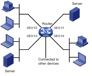
Network requirements
As shown in Figure 16, different departments of a company assigned to different VLANs are interconnected on the intranet through the ports of a router.
Configure priority mapping, so that the router enqueues packets based on the 802.1p priority of packets.
The priority mapping table is user-defined.
Configuration procedure
# Enter system view.
<Router> system-view
# Enter inbound up-up priority mapping table view and modify the priority mapping table parameters.
[Router] qos map-table inbound up-up
[Router-maptbl-in-up-up] import 0 1 export 0
[Router-maptbl-in-up-up] import 2 3 export 1
[Router-maptbl-in-up-up] import 4 5 export 2
[Router-maptbl-in-up-up] import 6 7 export 3
[Router-maptbl-in-up-up] quit
# Configure the trusted priority type as auto for GigabitEthernet 2/1/1.
[Router] interface GigabitEthernet 2/1/1
[Router-GigabitEthernet2/1/1] qos trust auto
[Router-GigabitEthernet2/1/1] quit
# Configure the trusted priority type as auto for GigabitEthernet 2/1/2.
[Router] interface GigabitEthernet 2/1/2
[Router-GigabitEthernet2/1/2] qos trust auto
[Router-GigabitEthernet2/1/2] quit
# Configure the trusted priority type as auto for GigabitEthernet 2/1/3.
[Router] interface GigabitEthernet 2/1/3
[Router-GigabitEthernet2/1/3] qos trust auto
[Router-GigabitEthernet2/1/3] quit
# Configure the trusted priority type as auto for GigabitEthernet 2/1/4.
[Router] interface GigabitEthernet 2/1/4
[Router-GigabitEthernet2/1/4] qos trust auto
Congestion avoidance overview
Avoiding congestion before it occurs is a proactive approach to improving network performance. As a flow control mechanism, congestion avoidance actively drops packets when congestion is expected to occur or deteriorate by monitoring the utilization of network resources (such as queues or memory buffers) to alleviate the load on the network.
Compared with end-to-end flow control, this flow control mechanism controls the load of more flows in a router. When dropping packets from a source end, it cooperates with the flow control mechanism (such as TCP flow control) at the source end to regulate the network traffic size. The combination of the local packet drop policy and the source-end flow control mechanism helps maximize throughput and network use efficiency and minimize packet loss and delay.
Traditional packet drop policy
Tail drop is the traditional approach to congestion avoidance. In this approach, when the size of a queue reaches the maximum threshold, all the subsequent packets are dropped.
This results in global TCP synchronization. If packets from multiple TCP connections are dropped, these TCP connections go into the state of congestion avoidance and slow start to reduce traffic, but traffic peak occurs later. Consequently, the network traffic jitters all the time.
RED and WRED
You can use random early detection (RED) or weighted random early detection (WRED) to avoid global TCP synchronization.
Both RED and WRED avoid global TCP synchronization by randomly dropping packets. When the sending rate of a TCP session slows down after its packets are dropped, the other TCP sessions remain in high packet sending rates. Because always some TCP sessions in high sending rates exist, link bandwidth is utilized more efficiently.
The RED or WRED algorithm sets an upper threshold and lower threshold for each queue, and processes the packets in a queue following these rules:
· When the queue size is shorter than the lower threshold, no packet is dropped.
· When the queue size reaches the upper threshold, all subsequent packets are dropped.
· When the queue size is between the lower threshold and the upper threshold, the received packets are dropped at random. The drop probability in a queue increases along with the queue size under the maximum drop probability.
Different from RED, WRED determines differentiated drop policies for packets with different IP precedence values. Packets with a lower IP precedence are more likely to be dropped.
Average queue size
If the current queue size is compared with the upper threshold and lower threshold to determine the drop policy, bursty traffic is not fairly treated. To solve this problem, WRED compares the average queue size with the upper threshold and lower threshold to determine the drop probability.
The average queue size reflects the queue size change trend but is not sensitive to bursty queue size changes, and thus bursty traffic can be fairly treated. The average queue size is calculated using the formula: average queue size=previous average queue size×(1-2-n)+Current queue size ×2-n, where n can be configured with the qos wred weighting-constant command.
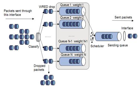
Relation between WRED and the queuing mechanism
The relation between WRED and the queuing mechanism is shown in Figure 17:
Figure 17 Relationship between WRED and queuing mechanism
Introduction to WRED configuration
|
|
NOTE: WRED is applicable to only SPE cards. |
Configuration methods
You can configure WRED by configuring a WRED table in system view and then apply the WRED table to an interface.
Introduction to wred parameters
Determine the following parameters before configuring WRED:
· Upper threshold and lower threshold—When the average queue size is smaller than the lower threshold, no packet is dropped. When the average queue size is between the lower threshold and the upper threshold, the packets are dropped at random. The longer the queue is, the higher the drop probability is. When the average queue size exceeds the upper threshold, subsequent packets are dropped.
· Drop precedence—A parameter used for packet drop. The value 0 corresponds to green packets, the value 1 corresponds to yellow packets, and the value 2 corresponds to red packets. Red packets are dropped preferentially.
· Exponent used for average queue size calculation—The bigger the exponent is, the more insensitive to real-time queue size changes the average queue size is.
· Denominator for drop probability calculation—The bigger the denominator is, the smaller the calculated drop probability is.
Configuring and applying a WRED table on an interface
Configuring and applying a queue-based wred table
To configure and apply a queue-based WRED table:
|
Step |
Command |
Remarks |
|
1. Enter system view. |
system-view |
N/A |
|
2. Create a WRED table and enter its view. |
qos wred queue table table-name |
N/A |
|
3. Set the WRED exponent for average queue size calculation. |
queue queue-number weighting-constant exponent |
Optional. The default setting is 8. |
|
4. Configure the other WRED parameters. |
queue queue-number [ drop-level drop-level ] low-limit low-limit high-limit high-limit [ discard-probability discard-prob ] |
Optional. By default, the low-limit is 10224, the high-limit is 10240, and the discard-prob is 100. |
|
5. Enter interface view or port group view. |
· Enter interface view: · Enter port group view: |
Use either command. Settings in interface view are effective on the current interface. Settings in port group view are effective on all ports in the port group. |
|
6. Apply the WRED table to the interface/port group. |
qos wred apply table-name |
N/A |
Displaying and maintaining WRED
|
Task |
Command |
Remarks |
|
Display WRED configuration information on interfaces. |
display qos wred interface [ interface-type interface-number ] [ | { begin | exclude | include } regular-expression ] |
Available in any view |
|
Display configuration information about a WRED table or all WRED tables. |
display qos wred table [ table-name ] [ | { begin | exclude | include } regular-expression ] |
Available in any view |
WRED configuration example
Network requirements
Apply a queue-based WRED table to interface GigabitEthernet 2/1/1.
Configuration procedure
# Enter system view
<Sysname> system-view
# Create a queue-based WRED table named queue-table1, and modify the lower and upper thresholds and drop probability for each queue.
|
|
NOTE: Configure the lower and upper thresholds for each queue in the WRED table depending on the interface buffer size, which varies by interface type. |
[sysname] qos wred queue table queue-table1
[Sysname-wred-table-queue-table1]queue 0 low-limit 128 high-limit 4096 discard-probability 100
[Sysname-wred-table-queue-table1]queue 1 low-limit 128 high-limit 2048 discard-probability 100
[Sysname-wred-table-queue-table1]queue 2 low-limit 128 high-limit 2048 discard-probability 100
[Sysname-wred-table-queue-table1]queue 3 low-limit 128 high-limit 2048 discard-probability 100
[Sysname-wred-table-queue-table1]queue 4 low-limit 128 high-limit 2048 discard-probability 100
[Sysname-wred-table-queue-table1]queue 5 low-limit 128 high-limit 512 discard-probability 100
[Sysname-wred-table-queue-table1]queue 6 low-limit 128 high-limit 512 discard-probability 100
[Sysname-wred-table-queue-table1]queue 7 low-limit 128 high-limit 8192 discard-probability 100
[Sysname-wred-table-queue-table1] quit
# Enter interface view.
[Sysname] interface GigabitEthernet 2/1/1
# Apply the WRED table to interface GigabitEthernet 2/1/1.
[Sysname-GigabitEthernet2/1/1] qos wred apply queue-table1
Aggregation CAR overview
Aggregation CAR uses the same CAR for traffic on multiple ports. If aggregation CAR is enabled for multiple ports, the total traffic on these ports must conform to the traffic policing parameters set in the aggregation CAR.
Referencing aggregation CAR in a traffic behavior
Configuration prerequisites
Decide on aggregation CAR parameters and the traffic behavior to reference the aggregation CAR.
Configuration procedure
To reference aggregation CAR in a traffic behavior:
|
Step |
Command |
Remarks |
|
1. Enter system view. |
system-view |
N/A |
|
2. Configure aggregation CAR parameters. |
qos car car-name aggregative cir committed-information-rate [ cbs committed-burst-size [ ebs excess-burst-size ] ] [ pir peek-information-rate ] [ red { discard | pass } ] |
By default: · CBS is half of the traffic transmitted over 500 ms at the rate of CIR. · EBS is 0 bytes. |
|
3. Enter traffic behavior view. |
traffic behavior behavior-name |
N/A |
|
4. Reference the aggregation CAR. |
car name car-name |
N/A |
|
5. Display traffic behavior configuration information. |
display traffic behavior user-defined [ behavior-name ] [ | { begin | exclude | include } regular-expression ] |
Optional. Available in any view |
|
6. Display information about the aggregation CAR. |
display qos car name [ car-name ] [ | { begin | exclude | include } regular-expression ] |
Configuration example
# Specify the aggregation CAR aggcar-1 to use the following parameters: CIR is 200, CBS is 2,000, and red packets are dropped. Reference aggregation CAR aggcar-1 in traffic behavior be1.
<Sysname> system-view
[Sysname] qos car aggcar-1 aggregative cir 200 cbs 2000 red discard
[Sysname] traffic behavior be1
[Sysname-behavior-be1] car name aggcar-1
Displaying and maintaining aggregation CAR
|
Task |
Command |
Remarks |
|
Display statistics about aggregation CAR policies. |
display qos car name [ car-name ] [ | { begin | exclude | include } regular-expression ] |
Available in any view |
|
Clear the statistics for aggregation CAR policies. |
reset qos car name [ car-name ] |
Available in any view |
|
|
NOTE: Queue scheduling profile configuration is applicable to only SPC cards. |
Introduction to queue scheduling profile
In a queue scheduling profile, you can configure scheduling parameters for each queue. By applying the queue scheduling profile to an interface, you can implement congestion management on the interface. You can modify the scheduling parameters in a queue scheduling profile already applied to an interface.
Queue scheduling profiles support two queue scheduling algorithms: SP and WRR. In a queue scheduling profile, you can configure SP, WRR, or both of them. When both algorithms are configured in a queue scheduling profile, SP queues and WRR groups are scheduled in the strict priority order, that is, in the descending order of queue ID, and in each WRR priority group, queues are scheduling based on their weights, as shown in Figure 18.
Figure 18 Queue scheduling profile configured with both SP and WRR
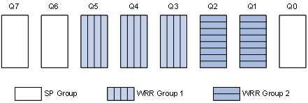
· Queue 7 has the highest priority. Its packets are sent preferentially.
· Queue 6 has the second highest priority. Packets in queue 6 are sent when queue 7 is empty.
· Queue 3, queue 4, and queue 5 are scheduled according to their weights. When both queue 6 and queue 7 are empty, WRR group 1 is scheduled.
· Queue 1 and queue 2 are scheduled according to their weights. WRR group 2 is scheduled when queue 7, queue 6, queue 5, queue 4, and queue 3 are all empty.
· Queue 0 has the lowest priority, and it is scheduled when all the other queues are empty.
Configuring a queue scheduling profile
To configure a queue scheduling profile, create the queue scheduling profile first, and then enter the queue scheduling profile view to configure its queue scheduling parameters. At last, apply the queue scheduling profile to the specified interface.
To configure a queue scheduling profile:
|
Step |
Command |
Remarks |
|
1. Enter system view. |
system-view |
N/A |
|
2. Create a queue scheduling profile and enter queue scheduling profile view. |
qos qmprofile profile-name |
N/A |
|
3. Configure queue scheduling parameters. |
· Configure a queue to use SP: · Configure a queue to use WRR: |
One queue can use only one queue scheduling algorithm. By default, queues are scheduled with SP. |
|
4. Exit to system view. |
quit |
N/A |
|
5. Enter interface view or port group view. |
· Enter interface view: · Enter port group view: |
Use either command. Settings in interface view are effective on the current interface. Settings in port group view are effective on all ports in the port group. |
|
6. Apply the queue scheduling profile to the interface or port group. |
qos apply qmprofile profile-name |
N/A |
|
|
NOTE: · Only one queue scheduling profile can be applied to an interface. · The queue IDs in a WRR group must be successive. If not, queue scheduling may be performed inaccurately. |
Displaying and maintaining queue scheduling profiles
|
Task |
Command |
Remarks |
|
Display the configuration of queue scheduling profiles. |
display qos qmprofile configuration [ profile-name ] [ | { begin | exclude | include } regular-expression ] |
Available in any view |
|
Display queue scheduling profiles already applied to interfaces. |
display qos qmprofile interface [ interface-type interface-number ] [ | { begin | exclude | include } regular-expression ] |
Available in any view |
Queue scheduling profile configuration example
Network requirements
Configure a queue scheduling profile on GigabitEthernet 3/1/1 to do the following:
· Assign queue 7 the highest priority to forward its packets preferentially.
· Assign queue 4, queue 5, and queue 6 to WRR group 1 to schedule them according to their weights, which are 1, 5, and 10, respectively. When queue 7 is empty, WRR group 1 is scheduled.
· Assign queue 1, queue 2, and queue 3 to WRR group 2 to schedule them according to their weights, which are 1, 10, and 20, respectively. When queues 4 to 7 are all empty, WRR group 2 is scheduled.
· Assign queue 0 the lowest priority. Queue 0 is scheduled when all the other queues are empty.
Configuration procedure
# Enter system view.
<Sysname> system-view
# Create queue scheduling profile qm1.
[Sysname] qos qmprofile qm1
[Sysname-qmprofile-qm1]
# Configure queue 7 to use SP queuing.
[Sysname-qmprofile-qm1] queue 7 sp
# Assign queue 4, queue 5, and queue 6 to WRR group 1, with the weight of 1, 5, and 10, respectively.
[Sysname-qmprofile-qm1] queue 4 wrr group 1 weight 1
[Sysname-qmprofile-qm1] queue 5 wrr group 1 weight 5
[Sysname-qmprofile-qm1] queue 6 wrr group 1 weight 10
# Assign queue 1, queue 2, and queue 3 to WRR group 2, with the weight of 1, 10, and 20, respectively.
[Sysname-qmprofile-qm1] queue 1 wrr group 2 weight 1
[Sysname-qmprofile-qm1] queue 2 wrr group 2 weight 10
[Sysname-qmprofile-qm1] queue 3 wrr group 2 weight 20
# Configure queue 0 to use SP queuing.
[Sysname-qmprofile-qm1] queue 0 sp
[Sysname-qmprofile-qm1] quit
# Apply queue scheduling profile qm1 to the incoming traffic of GigabitEthernet 3/1/1.
[Sysname] interface gigabitethernet 3/1/1
[Sysname-GigabitEthernet3/1/1] qos apply qmprofile qm1
After the configuration is completed, GigabitEthernet 3/1/1 performs queue scheduling as specified in queue scheduling profile qm1.
QoS traffic accounting overview
A router provides two counters to collect outbound and inbound traffic statistics.
You can configure each counter to collect statistics for traffic on a card, or traffic identified by any combination of interface, VLAN, local precedence, and drop precedence.
Per-port queue-based accounting overview
Per-port queue-based accounting collects statistics for each port on a per-queue basis, such as the number of forwarded or dropped packets.
|
|
NOTE: The per-port queue-based accounting function is enabled by default. You can use the display qos queue-statistics interface command to view the statistics. |
Configuring traffic accounting
To configure traffic accounting:
|
Step |
Command |
Remarks |
|
1. Enter system view. |
system-view |
N/A |
|
2. Enable traffic accounting and specify the type of traffic. |
qos traffic-counter { inbound | outbound } { counter0 | counter1 } slot slot-number [ interface interface-type interface-number | vlan vlan-id | local-precedence lp-value | drop-priority dp-value ] * |
By default, traffic accounting is disabled. |
|
|
NOTE: This feature is applicable to only the interfaces operating in bridge mode on SPC cards. |
Displaying and maintaining traffic accounting and per-port queue-based accounting
|
Task |
Command |
Remarks |
|
Display traffic statistics. |
display qos traffic-counter { inbound | outbound } { counter0 | counter1 } slot slot-number [ | { begin | exclude | include } regular-expression ] |
Available in any view |
|
Display statistics collected by the per-port queue-based accounting function. |
display qos queue-statistics interface [ interface-type interface-number ] [ pvc { pvc-name [ vpi/vci ] | vpi/vci } ] [ outbound ] [ | { begin | exclude | include } regular-expression ] |
Available in any view |
|
Clear the traffic statistics collected by a counter. |
reset qos traffic-counter { inbound | outbound } { counter0 | counter1 } slot slot-number |
Available in user view |
