- Table of Contents
-
- 06-Layer 2—LAN Switching Configuration Guide
- 00-Preface
- 01-MAC address table configuration
- 02-Ethernet link aggregation configuration
- 03-M-LAG configuration
- 04-Port isolation configuration
- 05-VLAN configuration
- 06-MVRP configuration
- 07-QinQ configuration
- 08-VLAN mapping configuration
- 09-Loop detection configuration
- 10-Spanning tree configuration
- 11-LLDP configuration
- 12-PFC configuration
- 13-L2PT configuration
- 14-Service loopback group configuration
- Related Documents
-
| Title | Size | Download |
|---|---|---|
| 03-M-LAG configuration | 753.55 KB |
Keepalive and failover mechanism
Configuration consistency check
M-LAG failure handling mechanisms
Mechanisms to handle concurrent peer link and keepalive link failures
Multichassis configuration synchronization
Restrictions and guidelines: M-LAG configuration
Compatibility with other features
Configuring multichassis configuration sync
Restrictions and guidelines for multichassis configuration sync
Synchronizing the configurations in real time
Bulk synchronizing the configurations
Fast configuring differential settings
Backing up and restoring a configuration file
Configuring M-LAG system settings
Configuring the M-LAG system MAC address
Setting the M-LAG system number
Setting the M-LAG system priority
Setting the M-LAG role priority of the device
Enabling M-LAG standalone mode on an M-LAG member device
Configuring M-LAG keepalive settings
Restrictions and guidelines for configuring M-LAG keepalive settings
Configuring M-LAG keepalive packet parameters
Setting the M-LAG keepalive interval and timeout timer
Associating the keepalive link with a track entry
Restrictions and guidelines for M-LAG MAD
Configuring the default M-LAG MAD action on network interfaces
Excluding an interface from the shutdown action by M-LAG MAD
Excluding all logical interfaces from the shutdown action by M-LAG MAD
Specifying interfaces to be shut down by M-LAG MAD when the M-LAG system splits
Enabling M-LAG MAD DOWN state persistence
Configuring an M-LAG interface
Specifying a Layer 2 aggregate interface or VXLAN tunnel interface as the peer-link interface
Reserving VLANs for the peer link
Enabling the short DRCP timeout timer on the peer-link interface or an M-LAG interface
Enabling the peer-link interface to retain MAC address entries for down single-homed devices
Assigning an M-LAG virtual IP address to an interface
Setting the mode of configuration consistency check
Disabling configuration consistency check
Setting the keepalive hold timer for identifying the cause of peer link down events
Configuring M-LAG system auto-recovery
Setting the data restoration interval
Enabling M-LAG sequence number check
Enabling M-LAG packet authentication
Verifying and maintaining M-LAG
Verifying M-LAG system configuration and running status
Displaying M-LAG interface information
Displaying and clearing DRCPDU statistics
Displaying and clearing M-LAG troubleshooting records
Example: Configuring basic M-LAG functions
Example: Configuring Layer 3 gateways on an M-LAG system
Comparison between M-LAG and DRNI commands
Configuring M-LAG
About M-LAG
Multichassis Link Aggregation (M-LAG) virtualizes two physical devices into one system through multichassis link aggregation.
M-LAG network model
As shown in Figure 1, M-LAG virtualizes two devices into a M-LAG system, which connects to the remote aggregation system through a multichassis aggregate link. To the remote aggregation system, the M-LAG system is one device.

The M-LAG member devices are M-LAG peers to each other. M-LAG defines the following interface roles for each M-LAG member device:
· M-LAG interface—Layer 2 aggregate interface connected to the remote aggregation system. M-LAG interfaces connected to the same remote aggregation system belong to one M-LAG group. In Figure 1, Bridge-Aggregation 1 on Device A and Bridge-Aggregation 2 on Device B belong to the same M-LAG group. M-LAG interfaces in an M-LAG group form a multichassis aggregate link.
· Peer-link interface—Interface connected to the M-LAG peer for internal control. Each M-LAG member device has only one peer-link interface. The peer-link interfaces of the M-LAG member devices transmit M-LAG protocol packets through the peer link established between them. An M-LAG system has only one peer link.
M-LAG member devices use a keepalive link to monitor each other's state. For more information about the keepalive mechanism, see "Keepalive and failover mechanism."
If a device is attached to only one of the M-LAG member devices in an M-LAG system, that device is a single-homed device.
To prevent packet loss after the peer link recovers from a link fault, the secondary member device should try to synchronize entries (such as the MAC address entries and ARP entries) within the data restoration interval. Subsequently, interfaces in M-LAG MAD DOWN state on the device will restore to up.
Roles of M-LAG member devices
For features that require centralized traffic processing (for example, spanning tree), an M-LAG member device is assigned the primary or secondary role based on its M-LAG role priority. The secondary M-LAG device passes the traffic of those features to the primary M-LAG device for processing. If the M-LAG member devices in an M-LAG system have the same M-LAG role priority, the device with the lower bridge MAC address is assigned the primary role.
DRCP
M-LAG uses Distributed Relay Control Protocol (DRCP) for multichassis link aggregation. DRCP runs on the peer link and uses M-LAG control protocol data units (DRCPDUs) to advertise the M-LAG configuration out of peer-link interfaces and M-LAG interfaces. DRCP is an H3C-proprietary protocol.
DRCP operating mechanism
M-LAG-enabled devices use DRCPDUs for the following purposes:
· Exchange DRCPDUs through M-LAG interfaces to determine whether they can form an M-LAG system.
· Exchange DRCPDUs through peer-link interfaces to negotiate the peer link state.
DRCP timeout timers
DRCP uses a timeout mechanism to specify the amount of time that a peer-link interface or M-LAG interface must wait to receive DRCPDUs before it determines that the peer interface is down. This timeout mechanism provides the following timer options:
· Short DRCP timeout timer, which is fixed at 3 seconds. If this timer is used, the peer interface sends one DRCPDU every second.
· Long DRCP timeout timer, which is fixed at 90 seconds. If this timer is used, the peer interface sends one DRCPDU every 30 seconds.
Short DRCP timeout timer enables the M-LAG member devices to detect a peer interface down event more quickly than the long DRCP timeout timer. However this benefit is at the expense of bandwidth and system resources.
Keepalive and failover mechanism
For the secondary M-LAG device to monitor the state of the primary device, you must establish a Layer 3 keepalive link between the M-LAG member devices.
The M-LAG member devices periodically send H3C-proprietary keepalive packets over the keepalive link. If an M-LAG member device has not received keepalive packets from the peer when the keepalive timeout timer expires, it determines that the keepalive link is down. When both the keepalive link and the peer link are down, an M-LAG member device acts depending on its role.
· If its role is primary, the device retains its role as long as it has up M-LAG interfaces. If all its M-LAG interfaces are down, its role becomes None.
· If its role is secondary, the device takes over the primary role and retains the role as long as it has up M-LAG interfaces. If all its M-LAG interfaces are down, its role becomes None.
A device with the None role cannot send or receive keepalive packets. Its keepalive link stays in the down state.
If the keepalive link is down while the peer link is up, the M-LAG member devices prompt you to check for keepalive link issues.
If the keepalive link is up while the peer link is down, the M-LAG member devices elect a primary device based on the information in the keepalive packets.
MAD mechanism
M-LAG MAD
A multi-active collision occurs if the peer link goes down while the keepalive link is up. To avoid network issues, M-LAG MAD shuts down all network interfaces on the secondary M-LAG member device except those manually or automatically excluded.
When the peer link comes up, the secondary M-LAG member device starts a delay timer and begins to restore table entries (including MAC address entries and ARP entries) from the primary M-LAG member device. When the delay timer expires, the secondary M-LAG member device brings up all network interfaces placed in M-LAG MAD DOWN state.
M-LAG MAD DOWN state persistence
Both of the M-LAG member devices might take the primary role if both of them have M-LAG interfaces in up state after the following series of events occur:
1. The peer link goes down while the keepalive link is up. Then, M-LAG MAD shuts down all network interfaces on the secondary M-LAG member device except those excluded from the shutdown action by M-LAG MAD.
2. The keepalive link also goes down. Then, the secondary M-LAG member device brings up the network interfaces in M-LAG MAD DOWN state and sets its role to primary.
M-LAG MAD DOWN state persistence helps avoid the forwarding issues that might occur in the multi-active situation that occurs because the keepalive link goes down while the peer link is down.
Device role calculation
As shown in Figure 2, the role of an M-LAG member device can be primary, secondary, or none after role calculation.
Figure 2 M-LAG role calculation process
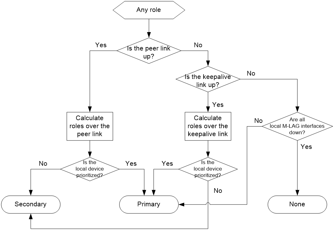
Role calculation rules
M-LAG calculates the roles of the M-LAG member devices according to the following rules:
· The M-LAG roles are determined upon M-LAG system initialization triggered by M-LAG system setup or reboot of an M-LAG member device.
· If the peer link is up, the M-LAG member devices exchange DRCPDUs over the peer link to determine which of them to take the primary role.
· If the peer link is down while the keepalive link is up, the M-LAG member devices exchange keepalive packets over the link to determine their roles.
· If both the peer link and the keepalive link are down, an M-LAG member device takes the primary role if it has available M-LAG interfaces.
Factors in role calculation
When the peer link or keepalive link is up, the M-LAG member devices exchange the following information to determine which of them takes the primary role:
1. Status of M-LAG interfaces. An M-LAG member device takes the primary role if it has available M-LAG interfaces. This status is skipped if role calculation is performed over the peer link.
2. Device roles before calculation. If one device already has the primary role, the primary device retains its role.
3. M-LAG MAD DOWN state. If one device has not placed any network interfaces in M-LAG MAD DOWN state, it becomes the primary device.
4. Health state. The healthier device takes the primary role.
5. M-LAG role priority. The device with higher M-LAG role priority takes the primary role.
6. Bridge MAC address. The device with a lower bridge MAC address takes the primary role.
The device that has failed the election takes the secondary role.
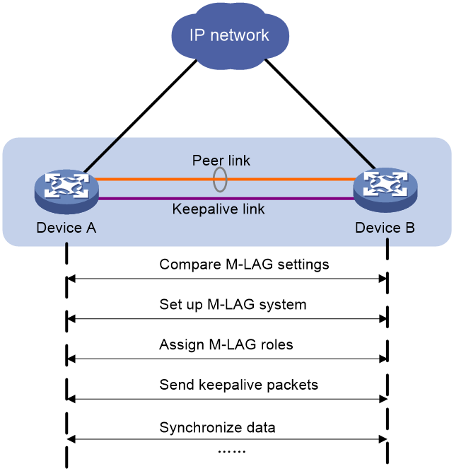
M-LAG system setup process
As shown in Figure 3, two devices perform the following operations to form an M-LAG system:
1. Send DRCPDUs over the peer link to each other and compare the DRCPDUs to determine the M-LAG system stackability and device roles:
a. Compare the M-LAG system settings. The devices can form an M-LAG system if they have consistent M-LAG system settings.
b. Determine the device roles as described in "Device role calculation."
c. Perform configuration consistency check. For more information, see "M-LAG standalone mode."
2. Send keepalive packets over the keepalive link after primary M-LAG member election to verify that the peer system is operating correctly.
3. Synchronize configuration data by sending DRCPDUs over the peer link. The configuration data includes MAC address entries and ARP entries.
Figure 3 M-LAG system setup process
M-LAG standalone mode
The M-LAG member devices might both operate with the primary role to forward traffic if they have M-LAG interfaces in up state after the M-LAG system splits. M-LAG standalone mode helps avoid traffic forwarding issues in this multi-active situation by allowing only the member ports in the M-LAG interfaces on one member device to forward traffic.
The following information describes the operating mechanism of this feature.
The M-LAG member devices change to M-LAG standalone mode when they detect that both the peer link and the keepalive link are down. In addition, the secondary M-LAG member device changes its role to primary.
In M-LAG standalone mode, the LACPDUs sent out of an M-LAG interface by each M-LAG member device contain the interface-specific LACP system MAC address and LACP system priority.
The Selected state of the member ports in the M-LAG interfaces in an M-LAG group depends on their LACP system MAC address and LACP system priority. If an M-LAG interface has a lower LACP system priority value or LACP system MAC address, the member ports in that M-LAG interface become Selected to forward traffic. If those Selected ports fail, the member ports in the M-LAG interface on the other M-LAG member device become Selected to forward traffic.
|
|
NOTE: An M-LAG member device changes to M-LAG standalone mode only when it detects that both the peer link and the keepalive link are down. It does not change to M-LAG standalone mode when the peer M-LAG member device reboots. |
Configuration consistency check
During M-LAG system setup, M-LAG member devices exchange the configuration and perform configuration consistency check to verify their consistency in the following configurations:
· Type 1 configuration—Settings that affect traffic forwarding of the M-LAG system. If an inconsistency in type 1 configuration is detected, the secondary M-LAG device shuts down its M-LAG interfaces.
· Type 2 configuration—Settings that affect only service features. If an inconsistency in type 2 configuration is detected, the secondary M-LAG device disables the affected service features, but it does not shut down its M-LAG interfaces.
To prevent interface flapping, the M-LAG system performs configuration consistency check when half the data restoration interval elapses.
|
|
NOTE: The data restoration interval specifies the maximum amount of time for the secondary M-LAG device to synchronize data with the primary M-LAG device during M-LAG system setup. For more information, see "Setting the data restoration interval." |
Type 1 configuration
Type 1 configuration consistency check is performed both globally and on M-LAG interfaces. Table 1 and Table 2 show settings that type 1 configuration contains.
Table 1 Global type 1 configuration
|
Setting |
Details |
|
Peer-link interface link type |
Peer-link interface link type, including access, hybrid, and trunk. |
|
PVID on the peer-link interface |
PVID on the peer-link interface. |
|
Spanning tree state |
· Global spanning tree state. · VLAN-specific spanning tree state. M-LAG checks the VLAN-specific spanning tree state only when PVST is enabled. |
|
Spanning tree mode |
Spanning tree mode, including STP, RSTP, PVST, and MSTP. |
|
MST region settings |
· MST region name. · MST region revision level. · VLAN-to-MSTI mappings. |
Table 2 M-LAG interface type 1 configuration
|
Setting |
Details |
|
Aggregation mode |
Aggregation mode, including static and dynamic. |
|
Spanning tree state |
Interface-specific spanning tree state. |
|
Link type |
Interface link type, including access, hybrid, and trunk. |
|
PVID |
Interface PVID. |
Type 2 configuration
Type 2 configuration consistency check is performed both globally and on M-LAG interfaces. Table 3 and Table 4 show settings that type 2 configuration contains.
Table 3 Global type 2 configuration
|
Setting |
Details |
|
VLANs permitted by the peer-link interface |
VLANs permitted by the peer-link interface. The M-LAG system compares tagged VLANs prior to untagged VLANs. |
|
VLAN interfaces |
Up VLAN interfaces of which the VLANs contain the peer-link interface. |
|
VLAN interface status |
Whether a VLAN interface is in administratively down state. |
|
IPv4 address of a VLAN interface |
IPv4 address assigned to a VLAN interface. |
|
IPv6 address of a VLAN interface |
IPv6 address assigned to a VLAN interface. |
|
Virtual IPv4 address of the VRRP group on a VLAN interface |
Virtual IPv4 address of the VRRP group configured on a VLAN interface on the master. |
|
Global BPDU guard |
Global status of BPDU guard. |
|
MAC aging timer |
Aging timer for dynamic MAC address entries. |
|
Authentication load sharing mode for users on port security-enabled M-LAG interfaces |
This setting is not supported in the current software version. Authentication load sharing mode for users on port security-enabled M-LAG interfaces: · Centralized—The primary M-LAG member device authenticates users. · Local—Each M-LAG member device authenticates their local users. · Odd-MAC—The local M-LAG member device authenticates odd-MAC users on all M-LAG interfaces of the M-LAG system. · Even-MAC—The local M-LAG member device authenticates even-MAC users on all M-LAG interfaces of the M-LAG system. |
|
MAC move |
Status of the MAC move feature. |
|
MAC move mode |
Port security MAC move mode: · Port—Allows an authenticated online user to move between ports on the device. · VLAN—Allows an authenticated online user to move between VLANs on a trunk or hybrid port. · All—Allows an authenticated online user to move between ports on the device or VLANs on a trunk or hybrid port. |
|
802.1X authentication method |
This setting is not supported in the current software version. 802.1X authentication method: · Chap—Performs EAP termination and uses CHAP to communicate with the RADIUS server. · Eap—Relays EAP packets and supports any of the EAP authentication methods to communicate with the RADIUS server. · Pap—Performs EAP termination and uses PAP to communicate with the RADIUS server. |
|
MAC authentication method |
This setting is not supported in the current software version. MAC authentication method: · Chap—CHAP authentication. · Pap—PAP authentication. |
|
VSI name |
Name of a VSI that has ACs on an M-LAG interface. |
|
VXLAN ID |
VXLAN ID of a VSI. |
|
Gateway interface |
VSI interface associated with a VSI. |
|
VSI interface number |
Number of a VSI interface. |
|
MAC address of a VSI interface |
MAC address assigned to a VSI interface. |
|
IPv4 address of a VSI interface |
IPv4 address assigned to a VSI interface. |
|
IPv6 address of a VSI interface |
IPv6 address assigned to a VSI interface. |
|
Physical state of a VSI interface |
Physical link state of a VSI interface. |
|
Protocol state of a VSI interface |
Data link layer state of a VSI interface. |
The device displays the following global type 2 settings only when VLAN or VLAN interface configuration inconsistency exists:
· VLAN interface status.
· IPv4 address of a VLAN interface.
· IPv6 address of a VLAN interface.
· Virtual IPv4 address of the VRRP group on a VLAN interface.
Table 4 M-LAG interface type 2 configuration
|
Setting |
Details |
|
VLANs permitted by an M-LAG interface |
VLANs permitted by an M-LAG interface. The M-LAG system compares tagged VLANs prior to untagged VLANs. |
|
Using port speed as the prioritized criterion for reference port selection |
Whether an M-LAG interface uses port speed as the prioritized criterion for reference port selection. |
|
Ignoring port speed in setting the aggregation states of member ports |
Whether an M-LAG interface ignores port speed in setting the aggregation states of member ports. |
|
Root guard status |
Status of root guard. |
|
Port security mode |
This setting is not supported in the current software version. Port security mode: · Autolearn. · Mac-authentication. · Mac-else-userlogin-secure. · Mac-else-userlogin-secure-ext. · Secure. · Userlogin. · Userlogin-secure. · Userlogin-secure-ext. · Userlogin-secure-or-mac. · Userlogin-secure-or-mac-ext. · Userlogin-withoui. |
|
802.1X critical VSI name |
This setting is not supported in the current software version. Name of the 802.1X critical VSI. |
|
802.1X online user handshake |
This setting is not supported in the current software version. Status of the 802.1X online user handshake feature. |
|
802.1X multicast trigger |
This setting is not supported in the current software version. Status of the 802.1X multicast trigger feature. |
|
802.1X unicast trigger |
This setting is not supported in the current software version. Status of the 802.1X unicast trigger feature. |
|
MAC authentication critical microsegment ID |
This setting is not supported in the current software version. ID of the MAC authentication critical microsegment. |
|
MAC authentication critical VSI name |
This setting is not supported in the current software version. Name of the MAC authentication critical VSI. |
|
MAC authentication URL user logoff |
This setting is not supported in the current software version. Whether to log off MAC authentication users that have been assigned authorization URLs and have not passed authentication on a port when the first user is assigned to the critical microsegment. |
|
Parallel processing of MAC authentication and 802.1X authentication on a port |
This setting is not supported in the current software version. Status of parallel processing of MAC authentication and 802.1X authentication on a port. |
|
Web authentication Auth-Fail VLAN |
This setting is not supported in the current software version. Auth-Fail VLAN for Web authentication. |
M-LAG sequence number check
M-LAG sequence number check protects M-LAG member devices from replay attacks.
With this feature enabled, the M-LAG member devices insert a sequence number into each outgoing DRCPDU or keepalive packet and the sequence number increases by 1 for each sent packet. When receiving a DRCPDU or keepalive packet, the M-LAG member devices check its sequence number and drop the packet if the check result is either of the following:
· The sequence number of the packet is the same as that of a previously received packet.
· The sequence number of the packet is smaller than that of the most recently received packet.
M-LAG packet authentication
M-LAG packet authentication prevents DRCPDU and keepalive packet tampering from causing link flapping.
With this feature enabled, the M-LAG member devices compute a message digest by using an authentication key for each outgoing DRCPDU or keepalive packet and insert the message digest into the packet. When receiving a DRCPDU or keepalive packet, an M-LAG member device computes a message digest and compares it with the message digest in the packet. If the message digests match, the packet passes authentication. If the message digests do not match, the device drops the packet.
M-LAG failure handling mechanisms
M-LAG interface failure handling mechanism
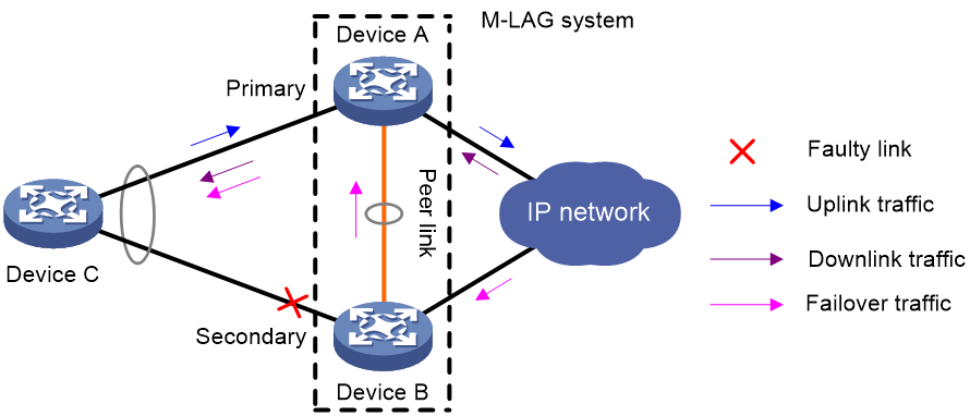
As shown in Figure 4, Device A and Device B form an M-LAG system, to which Device C is attached through a multichassis aggregation. If traffic to Device C arrives at Device B after the M-LAG interface connected Device B to Device C has failed, the M-LAG system forwards the traffic as follows:
1. Device B sends the traffic to Device A over the peer link.
2. Device A forwards the downlink traffic received from the peer link to Device C.
After the faulty M-LAG interface comes up, Device B forwards traffic to Device C through the M-LAG interface.
Figure 4 M-LAG interface failure handling mechanism
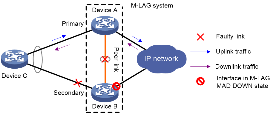
peer link failure handling mechanism
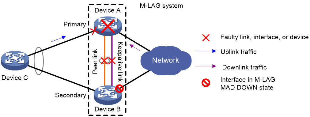
As shown in Figure 5, multi-active collision occurs if the peer link goes down while the keepalive link is up. To avoid network issues, the secondary M-LAG device sets all network interfaces to M-LAG MAD DOWN state, except for the interfaces excluded from the shutdown action by M-LAG MAD.
In this situation, the primary M-LAG device forwards all traffic for the M-LAG system.
When the peer-link interface comes up, the secondary M-LAG device does not bring up the network interfaces immediately. Instead, it starts a delay timer and begins to recover data from the primary M-LAG device. When the delay timer expires, the secondary M-LAG device brings up all network interfaces.
Figure 5 peer link failure handling mechanism
Device failure handling mechanism
As shown in Figure 6, when the primary M-LAG device fails, the secondary M-LAG device takes over the primary role to forward all traffic for the M-LAG system. When the faulty device recovers, it becomes the secondary M-LAG device.
When the secondary M-LAG device fails, the primary M-LAG device forwards all traffic for the M-LAG system.
Figure 6 Device failure handling mechanism
Uplink failure handling mechanism
Uplink failure does not interrupt traffic forwarding of the M-LAG system. As shown in Figure 7, when the uplink of Device A fails, Device A passes traffic destined for the IP network to Device B for forwarding.
To enable faster traffic switchover in response to an uplink failure and minimize traffic losses, configure Monitor Link to associate the M-LAG interfaces with the uplink interfaces. When the uplink interface of an M-LAG member device fails, that device shuts down its M-LAG interface for the other M-LAG member device to forward all traffic of Device C. For more information about Monitor Link, see High Availability Configuration Guide.
Figure 7 Uplink failure handling mechanism
Mechanisms to handle concurrent peer link and keepalive link failures
When both the peer link and the keepalive link are down, the M-LAG member devices handle this situation depending on your configuration.
Default failure handling mechanism
Figure 8 shows the default mechanism to handle peer link and keepalive link failures when the M-LAG standalone mode and M-LAG MAD DOWN state persistency features are not configured.
· If the peer link goes down while the keepalive link is up, the M-LAG member devices negotiate their roles over the keepalive link. M-LAG MAD shuts down all network interfaces on the secondary M-LAG member device except those excluded from the shutdown action by M-LAG MAD.
· If the keepalive link goes down while the peer link is down, the secondary M-LAG member device sets its role to primary and brings up the network interfaces in M-LAG MAD DOWN state to forward traffic. In this situation, both of the M-LAG member devices might operate with the primary role to forward traffic. Forwarding errors might occur because the M-LAG member devices cannot synchronize MAC address entries over the peer link.
· If the keepalive link is down before the peer link goes down, M-LAG MAD will not place network interfaces in M-LAG MAD DOWN state. Both M-LAG member devices can operate with the primary role to forward traffic.
Figure 8 Default failure handling mechanism
Failure handling mechanism with M-LAG MAD DOWN state persistence
Figure 9 shows the mechanism to handle peer link and keepalive link failures when the M-LAG MAD DOWN state persistence feature is configured.
· If the peer link goes down while the keepalive link is up, the M-LAG member devices negotiate their roles over the keepalive link. M-LAG MAD shuts down all network interfaces on the secondary M-LAG member device except those excluded from the shutdown action by M-LAG MAD.
· If the keepalive link goes down while the peer link is down, the secondary M-LAG member device sets its role to primary, but it does not bring up the network interfaces in M-LAG MAD DOWN state. Only the original primary member device can forward traffic.
· If the keepalive link is down before the peer link goes down, M-LAG MAD will not place network interfaces in M-LAG MAD DOWN state. Both M-LAG member devices can operate with the primary role to forward traffic.
Figure 9 Failure handling mechanism with M-LAG MAD DOWN state persistence
As shown in Figure 10, you can bring up the interfaces in M-LAG MAD DOWN state on the secondary M-LAG member device for it to forward traffic if the following conditions exist:
· Both the peer link and the keepalive link are down.
· The primary M-LAG member device fails or its M-LAG interface fails.
Figure 10 Bringing up the interfaces in M-LAG MAD DOWN state
Failure handling mechanism with M-LAG standalone mode
Figure 11 shows the mechanism to handle peer link and keepalive link failures when the M-LAG standalone mode feature is configured.
· If the peer link goes down while the keepalive link is up, the M-LAG member devices negotiate their roles over the keepalive link. M-LAG MAD shuts down all network interfaces on the secondary M-LAG member device except those excluded from the shutdown action by M-LAG MAD.
· If the keepalive link goes down while the peer link is down, both M-LAG member devices change to M-LAG standalone mode. The secondary M-LAG member device sets its role to primary and brings up its network interfaces in M-LAG MAD DOWN state. In M-LAG standalone mode, only the aggregation member ports on one M-LAG member device can become Selected to forward traffic. For more information about how M-LAG standalone mode operates, see "M-LAG standalone mode."
· If the keepalive link is down before the peer link goes down, both M-LAG member devices change to M-LAG standalone mode.
Figure 11 Failure handling mechanism with M-LAG standalone mode

Multichassis configuration synchronization
Multichassis configuration synchronization (sync) allows you to synchronize and back up configurations between multiple devices to simplify the configuration procedure, improve deployment efficiency, and optimize user experience. For example, after you configure one M-LAG member device, you can synchronize its configuration to the other M-LAG member device over the peer link for them to have identical configuration.
This feature is applicable only to an M-LAG system currently.
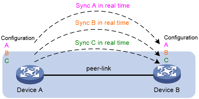
Real-time configuration sync
As shown in Figure 12, settings in multichassis configuration sync view of a member device are synchronized to its peer device in real time.
Figure 12 Real-time configuration sync
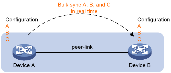
Bulk configuration sync
To fast deploy the services that are required to be consistent across the M-LAG member devices, configure the services on an M-LAG member device before M-LAG system setup. After the M-LAG system is set up and the peer link comes up, you can bulk synchronize settings on the member device to the same view for multichassis configuration sync on the M-LAG peer, as shown in Figure 13.
Figure 13 Bulk configuration sync
Configuration backup
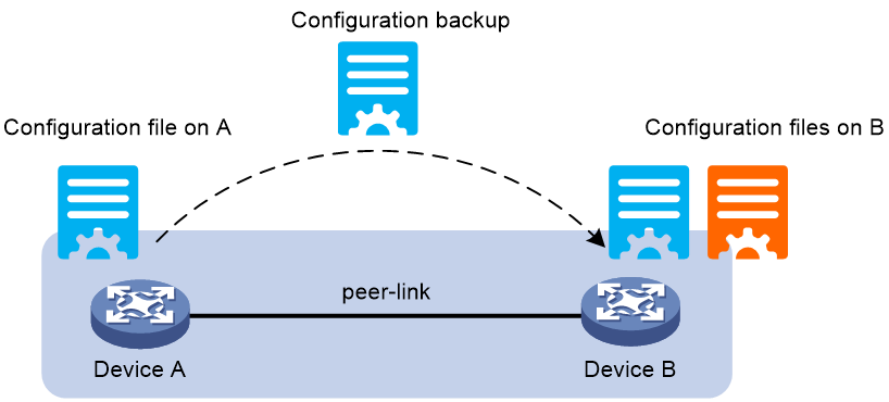
If you are to update an M-LAG member device, for example, update the software version or replace the device, back up its configuration file to the M-LAG peer in advance as shown in Figure 14. After the update is completed, you can retrieve the previously saved configuration file from the peer device.
Figure 14 Configuration backup
Protocols and standards
IEEE P802.1AX-REV™/D4.4c, Draft Standard for Local and Metropolitan Area Networks
Restrictions and guidelines: M-LAG configuration
M-LAG configuration
For the M-LAG member devices to be identified as one M-LAG system, you must configure the same M-LAG system MAC address and M-LAG system priority on them. You must assign different M-LAG system numbers to the M-LAG member devices.
Do not configure the same LACP system MAC address for the M-LAG interfaces in the same M-LAG group.
As a best practice to reduce the impact of interface flapping on upper-layer services, use the link-delay command to configure the same link delay settings on the peer-link interfaces.
To prevent data synchronization failure, you must set the same maximum jumbo frame length on the peer-link interfaces of the M-LAG member devices.
For the M-LAG system to correctly forward traffic for single-homed devices, set the link type to trunk for the peer-link interfaces and the interfaces attached to the single-homed devices. If you fail to do so, the ND protocol packets sent to or from the single-homed devices cannot be forwarded over the peer link.
To ensure correct forwarding, delete M-LAG configuration from an M-LAG member device if it leaves its M-LAG system.
As a best practice, establish a directly connected physical link between the M-LAG member devices as the keepalive link and use this link for the sole purpose of keepalive detection. When the keepalive link uses the IP address of a VLAN interface, do not assign the peer-link interface to the VLAN corresponding to the VLAN interface. If you do that, the keepalive mechanism might fail.
Compatibility with other features
IRF
M-LAG cannot work correctly on an IRF fabric. Do not configure M-LAG on an IRF fabric. For more information about IRF, see Virtual Technologies Configuration Guide.
MAC address table
If the M-LAG system has a large number of MAC address entries, set the MAC aging timer to a higher value than 20 minutes as a best practice. To set the MAC aging timer, use the mac-address timer command.
For more information about the MAC address table, see "Configuring the MAC address table."
Ethernet link aggregation
Do not configure automatic link aggregation on an M-LAG system.
The aggregate interfaces in an S-MLAG group cannot be used as M-LAG interfaces or peer-link interfaces.
When you configure an M-LAG interface, follow these restrictions and guidelines:
· The link-aggregation selected-port maximum and link-aggregation selected-port minimum commands do not take effect on an M-LAG interface.
· If you execute the display link-aggregation verbose command for an M-LAG interface, the displayed system ID contains the M-LAG system MAC address and the M-LAG system priority.
· If the reference port is a member port of an M-LAG interface, the display link-aggregation verbose command displays the reference port on both M-LAG member devices.
For more information about Ethernet link aggregation, see "Configuring Ethernet link aggregation."
Port isolation
Do not assign M-LAG interfaces or peer-link interfaces to a port isolation group. For more information about port isolation, see "Configuring port isolation."
Loop detection
Member devices in an M-LAG system must have the same loop detection configuration. For information about loop detection, see "Configuring loop detection."
Spanning tree
When the spanning tree protocol is enabled for an M-LAG system, follow these restrictions and guidelines:
· Make sure the M-LAG member devices have the same spanning tree configuration. Violation of this rule might cause network flapping. The configuration includes:
¡ Global spanning tree configuration.
¡ Spanning tree configuration on the peer-link interface.
¡ Spanning tree configuration on M-LAG interfaces.
· Peer-link interfaces of the M-LAG system do not participate in spanning tree calculation.
· The M-LAG member devices still use the M-LAG system MAC address after the M-LAG system splits, which will cause spanning tree calculation issues. To avoid the issues, enable M-LAG standalone mode on the M-LAG member devices before the M-LAG system splits.
For more information about spanning tree, see "Configuring spanning tree."
Multicast
You must directly connect a Layer 2 or Layer 3 multicast-enabled M-LAG system to a multicast source or multicast receivers. You cannot place the M-LAG system in any other location.
In PIM-SSM or IPv6 PIM-SSM mode, if multicast receivers are attached only to one M-LAG member device in the M-LAG system, make sure the receivers access the M-LAG member device through VLAN interfaces.
For more information about M-LAG for multicast, see PIM, IPv6 PIM, and IGMP Snooping configuration in IP Multicast Configuration Guide.
AAA
On an M-LAG system, you must specify a virtual IP address as the source IP address of outgoing RADIUS packets.
When RADIUS DAE is enabled, an M-LAG system does not support shutting down or rebooting the access ports for 802.1X authentication users or reauthenticating the users through CoA messages.
For more information about AAA, see Security Configuration Guide.
Smart Link
The M-LAG member devices in an M-LAG system must have the same Smart Link configuration.
For Smart Link to operate correctly on an M-LAG interface, do not assign the M-LAG interface and non-M-LAG interfaces to the same smart link group.
Do not assign a peer-link interface to a smart link group.
For more information about Smart Link configuration, see High Availability Configuration Guide.
VRRP
If you use M-LAG and VRRP together, make sure the keepalive hold timer is shorter than the interval at which the VRRP master sends VRRP advertisements. Violation of this restriction might cause a VRRP master/backup switchover to occur before peer link failure is confirmed. To set the interval at which the VRRP master sends VRRP advertisements, use the vrrp vrid timer advertise or vrrp ipv6 vrid timer advertise command. For more information about the commands, see High Availability Command Reference.
Mirroring
If you use port mirroring together with M-LAG, assign the source port, destination port, egress port, and reflector port for a mirroring group to the same aggregation group. If the source port is in a different aggregation group than the other ports, mirrored LACPDUs will be transmitted between aggregation groups and cause aggregate interface flapping.
VXLAN and EVPN
For information about VXLAN and EVPN restrictions, see VXLAN Configuration Guide and EVPN VXLAN configuration in EVPN Configuration Guide.
Support for DRNI commands
The M-LAG feature was named DRNI in earlier software versions. For compatibility with earlier software versions, the device supports both M-LAG and DRNI commands.
Table 5 Difference between M-LAG and DRNI commands
|
Feature name |
Keywords |
Example |
|
M-LAG |
m-lag, mlag, peer-link |
m-lag system-number system-number As a best practice, use M-LAG commands. |
|
DRNI |
drni, drmac, ipp |
drni system-number system-number To use configuration files created from an earlier software version, use DRNI commands. The system recognizes only the complete syntaxes of DRNI commands. It does not support displaying available keywords and arguments in response to a question mark (?) or automatically completing the last keyword or argument in response to the Tab key. If you execute a DRNI command, the system converts it into the corresponding M-LAG command and saves the M-LAG command in the configuration file. |
M-LAG and DRNI commands do not differ in the configuration method or functionality. For more information about the keyword differences, see "Comparison between M-LAG and DRNI commands."
M-LAG tasks at a glance
To configure M-LAG, perform the following tasks:
1. Configuring multichassis configuration sync
2. Configuring M-LAG system settings
¡ Configuring the M-LAG system MAC address
¡ Setting the M-LAG system number
¡ Setting the M-LAG system priority
3. Setting the M-LAG role priority of the device
4. (Optional.) Enabling M-LAG standalone mode on an M-LAG member device
5. Configuring M-LAG keepalive settings
¡ Configuring M-LAG keepalive packet parameters
¡ Setting the M-LAG keepalive interval and timeout timer
¡ Configuring the default M-LAG MAD action on network interfaces
¡ Excluding an interface from the shutdown action by M-LAG MAD
¡ Excluding all logical interfaces from the shutdown action by M-LAG MAD
¡ Specifying interfaces to be shut down by M-LAG MAD when the M-LAG system splits
¡ Enabling M-LAG MAD DOWN state persistence
7. Configuring M-LAG interfaces:
¡ Configuring an M-LAG interface
¡ Specifying a Layer 2 aggregate interface or VXLAN tunnel interface as the peer-link interface
¡ (Optional.) Enabling the short DRCP timeout timer on the peer-link interface or an M-LAG interface
8. (Optional.) Enabling the peer-link interface to retain MAC address entries for down single-homed devices
9. (Optional.) Assigning an M-LAG virtual IP address to an interface
10. (Optional.) Configuring configuration consistency check
¡ Setting the mode of configuration consistency check
¡ Disabling configuration consistency check
Configuration consistency check might fail when you upgrade the M-LAG member devices in an M-LAG system. To prevent the M-LAG system from falsely shutting down M-LAG interfaces, you can temporarily disable configuration consistency check.
11. (Optional.) Configuring M-LAG timers
¡ (Optional.) Setting the keepalive hold timer for identifying the cause of peer link down events
¡ Configuring M-LAG system auto-recovery
¡ (Optional.) Setting the data restoration interval
12. (Optional.) Configuring M-LAG security features
¡ Enabling M-LAG sequence number check
¡ Enabling M-LAG packet authentication
Configuring multichassis configuration sync
Restrictions and guidelines for multichassis configuration sync
Real-time or bulk configuration sync synchronizes only configurations required to be consistent across the M-LAG member devices.
Execute the mc-configure access-local enable command on both M-LAG member devices for them to access each another.
Before you use the multichassis configuration sync feature, verify that the M-LAG system is operating correctly and the peer link is up.
For more information about the multichassis configuration sync commands, see Fundamentals Command Reference.
Synchronizing the configurations in real time
About this task
This feature enables commands executed in multichassis configuration sync view on an M-LAG member device to be synchronized to its M-LAG peer in real time.
Procedure
1. Enter system view.
system-view
2. Permit the M-LAG peer to access the local device via the sync channel.
mc-configure access-local enable
By default, the M-LAG peer is permitted to access the local device via the sync channel.
3. Return to user view.
quit
4. Enter multichassis configuration sync view.
system-view mc-config
Commands executed in any view for multichassis configuration sync will be synchronized to the M-LAG peer in real time.
Bulk synchronizing the configurations
About this task
To fast deploy the services that are required to be consistent across the M-LAG member devices, configure the services on an M-LAG member device before M-LAG system setup. After the M-LAG system is set up and the peer link comes up, you can use this feature to bulk synchronize settings on the member device to the same view for multichassis configuration sync on the M-LAG peer.
Procedure
1. Enter system view.
system-view
2. Permit the M-LAG peer to access the local device via the sync channel.
mc-configure access-local enable
By default, the M-LAG peer is permitted to access the local device via the sync channel.
3. Configure required settings in system view or any view under system view.
4. Return to user view.
quit
5. Enter multichassis configuration sync view.
system-view mc-config
6. Bulk synchronize the settings to the M-LAG peer.
mc-configure batch-synchronize
You can execute this command in any view for multichassis configuration sync.
Fast configuring differential settings
About this task
For settings required only on the local device, you can execute the mc-configure switch-to-local command in any view for multichassis configuration sync to switch to the same view of the local device and then configure the settings. To return to the original view for multichassis configuration sync after configuring the settings on the local device, execute the mc-configure quit command or press Ctrl+Q.
For the settings required only on the peer device, you can execute the mc-configure switch-to-peer in any view for multichassis configuration sync of the local device to switch to the same view of the peer device and then configure the settings. To return to the original view for multichassis configuration sync after configuring the settings on the peer device, execute the mc-configure quit command or press Ctrl+Q.
Configuring the differential settings on the local device
1. Enter multichassis configuration sync view.
system-view mc-config
2. Switch to the same view of the local device.
[@local] will be added to the commands executed in any view of the local device.
mc-configure switch-to-local
You can execute this command in any view for multichassis configuration sync.
3. Configure the differential commands on the local device.
4. Return to the original view for multichassis configuration sync.
mc-configure quit
Configuring the differential settings on the M-LAG peer
1. Enter multichassis configuration sync view.
system-view mc-config
2. Switch to the same view of the M-LAG peer.
[@peer] will be added to the commands executed in any view of the peer device.
mc-configure switch-to-local
You can execute this command in any view for multichassis configuration sync.
3. Configure the differential commands on the M-LAG peer.
4. Return to the original view for multichassis configuration sync.
mc-configure quit
Backing up and restoring a configuration file
About this task
To update an M-LAG member device, for example, update the software version or replace the device, you can the mc-configure backup-to-peer command to back up its configuration file to the M-LAG peer in advance. After the update is completed, you can use the mc-configure get-from-peer command to retrieve the previously saved configuration file from the peer device and replace the configuration file on the local device.
Procedure
Execute the following command in user view to save the local configuration file to the M-LAG peer.
mc-configure backup-to-peer local-filename
Execute the following command in user view to retrieve the configuration file from the M-LAG peer.
mc-configure get-from-peer filename
Configuring M-LAG system settings
Configuring the M-LAG system MAC address
Restrictions and guidelines
The M-LAG system MAC address uniquely identifies the M-LAG system on the network. On an M-LAG system, M-LAG interfaces in the same M-LAG group must use the same LACP system MAC address. As a best practice, use the bridge MAC address of one M-LAG member device as the M-LAG system MAC address.
Changing the M-LAG system MAC address causes M-LAG system split. When you perform this task on a live network, make sure you are fully aware of its impact.
You can configure the M-LAG system MAC address on an aggregate interface only after it is configured as an M-LAG interface.
You can configure the M-LAG system MAC address globally and in aggregate interface view. The global M-LAG system MAC address takes effect on all aggregation groups. On an aggregate interface, the interface-specific M-LAG system MAC address takes precedence over the global M-LAG system MAC address.
Procedure
1. Enter system view.
system-view
2. Configure the M-LAG system MAC address.
m-lag system-mac mac-address
By default, the M-LAG system MAC address is not configured.
3. Enter Layer 2 aggregate interface view.
interface bridge-aggregation interface-number
4. Set the M-LAG system MAC address on the aggregate interface.
port m-lag system-mac mac-address
By default, the M-LAG system MAC address is not configured.
Setting the M-LAG system number
Restrictions and guidelines
Changing the M-LAG system number causes M-LAG system split. When you perform this task on a live network, make sure you are fully aware of its impact.
You must assign different M-LAG system numbers to the M-LAG member devices in an M-LAG system.
Procedure
1. Enter system view.
system-view
2. Set the M-LAG system number.
m-lag system-number system-number
By default, the M-LAG system number is not set.
Setting the M-LAG system priority
About this task
An M-LAG system uses its M-LAG system priority as the system LACP priority to communicate with the remote aggregation system.
Restrictions and guidelines
Changing the M-LAG system priority in system view causes M-LAG system split. When you perform this task on a live network, make sure you are fully aware of its impact.
You must configure the same M-LAG system priority for the M-LAG interfaces in the same M-LAG group.
You can configure the M-LAG system priority on an aggregate interface only after it is configured as an M-LAG interface.
You can configure the M-LAG system priority globally and in aggregate interface view. The global M-LAG system priority takes effect on all aggregation groups. On an aggregate interface, the interface-specific M-LAG system priority takes precedence over the global M-LAG system priority.
Procedure
1. Enter system view.
system-view
2. Set the M-LAG system priority.
m-lag system-priority system-priority
By default, the M-LAG system priority is 32768.
3. Enter Layer 2 aggregate interface view.
interface bridge-aggregation interface-number
4. Set the M-LAG system priority on the aggregate interface.
port m-lag system-priority priority
By default, the M-LAG system priority is 32768.
Setting the M-LAG role priority of the device
About this task
M-LAG assigns the primary or secondary role to an M-LAG member device based on its M-LAG role priority. The smaller the priority value, the higher the priority. If the M-LAG member devices in an M-LAG system use the same M-LAG role priority, the device with the lower bridge MAC address is assigned the primary role.
Restrictions and guidelines
To prevent a primary/secondary role switchover from causing network flapping, avoid changing the M-LAG priority assignment after the M-LAG system is established.
Procedure
1. Enter system view.
system-view
2. Set the M-LAG role priority of the device.
m-lag role priority priority-value
By default, the M-LAG role priority of the device is 32768.
Enabling M-LAG standalone mode on an M-LAG member device
About this task
Perform this task to avoid forwarding issues in the multi-active situation that might occur after both the peer link and the keepalive link are down.
M-LAG standalone mode helps avoid traffic forwarding issues in this multi-active situation by allowing only the member ports in the M-LAG interfaces on one member device to forward traffic. For more information about this mode, see "M-LAG standalone mode."
When you configure this feature, you can configure a delay to prevent an unnecessary mode change because of transient link down issues.
Restrictions and guidelines
As a best practice, enable M-LAG standalone mode on both M-LAG member devices.
If the MAC address of an M-LAG system does not correspond to any actual MAC address on any M-LAG member device, and the M-LAG interface contains multiple aggregation member ports, enabling the M-LAG standalone mode might cause the aggregation member ports of the M-LAG interface to flap. Make sure you are fully aware of the impact of this feature when you use it on a live network.
In a single-level M-LAG network, before you enable M-LAG standalone mode on an M-LAG member device, make sure its LACP system priority is higher than that of the remote aggregation system. This restriction ensures that the reference port is on the remote aggregation system and prevents the interfaces attached to the M-LAG system from flapping.
Procedure
1. Enter system view.
system-view
2. Enable M-LAG standalone mode.
m-lag standalone enable [ delay delay-time ]
By default, M-LAG standalone mode is disabled.
Configuring M-LAG keepalive settings
Restrictions and guidelines for configuring M-LAG keepalive settings
As a best practice, establish a dedicated direct link between M-LAG member devices as a keepalive link. Do not use the keepalive link for any other purposes. Make sure the M-LAG member devices have Layer 2 and Layer 3 connectivity to each other over the keepalive link.
Configuring M-LAG keepalive packet parameters
About this task
Perform this task to specify the parameters for sending M-LAG keepalive packets, such as its source and destination IP addresses.
The device accepts only keepalive packets that are sourced from the specified destination IP address. The keepalive link goes down if the device receives keepalive packets sourced from any other IP address.
Restrictions and guidelines
Make sure the M-LAG member devices in an M-LAG system use the same keepalive destination UDP port.
Procedure
1. Enter system view.
system-view
2. Configure M-LAG keepalive packet parameters.
m-lag keepalive { ip | ipv6 } destination { ipv4-address | ipv6-address } [ source { ipv4-address | ipv6-address } | [ udp-port udp-number | vpn-instance vpn-instance-name ] *
By default, the M-LAG keepalive packet parameters are not configured. If you do not specify a source IP address or destination UDP port when you execute this command, the IP address of the outgoing interface and UDP port 6400 are used, respectively.
Setting the M-LAG keepalive interval and timeout timer
About this task
The device sends keepalive packets at the specified interval to its M-LAG peer. If the device has not received a keepalive packet from the M-LAG peer before the keepalive timeout timer expires, the device determines that the keepalive link is down.
Restrictions and guidelines
The local M-LAG keepalive timeout timer must be two times the M-LAG keepalive interval of the peer at minimum.
Configure the same M-LAG keepalive interval on the M-LAG member devices in the M-LAG system.
Procedure
1. Enter system view.
system-view
2. Set the M-LAG keepalive interval and timeout timer.
m-lag keepalive interval interval [ timeout timeout ]
By default, the M-LAG keepalive interval is 1000 milliseconds, and the M-LAG keepalive timeout timer is 5 seconds.
Associating the keepalive link with a track entry
About this task
Associate a track entry with the keepalive link to fast detect state changes of the keepalive link. For more information about track entries, see Track configuration in High Availability Configuration Guide.
Restrictions and guidelines
As a best practice, do not specify the track entry associated with M-LAG MAD when executing m-lag keepalive track command. If you do that, the M-LAG system state might flap.
Procedure
1. Enter system view.
system-view
2. Associate the keepalive link with a track entry.
m-lag keepalive track track-entry-number
By default, no track entry is associated with the keepalive link.
Configuring M-LAG MAD
About this task
M-LAG MAD configuration methods
When you configure M-LAG MAD, use either of the following methods:
· To shut down all network interfaces on the secondary M-LAG member device except a few special-purpose interfaces that must be retained in up state:
¡ Set the default M-LAG MAD action to M-LAG MAD DOWN. For more information, see "Configuring the default M-LAG MAD action on network interfaces."
¡ Exclude interfaces from being shut down by M-LAG MAD. For more information, see "Excluding an interface from the shutdown action by M-LAG MAD."
This method is applicable to most network environments.
· To have the secondary M-LAG member device retain a large number of interfaces in up state and shut down the remaining interfaces:
¡ Set the default M-LAG MAD action to NONE. For more information, see "Configuring the default M-LAG MAD action on network interfaces."
¡ Specify network interfaces that must be shut down by M-LAG MAD. For more information, see "Specifying interfaces to be shut down by M-LAG MAD when the M-LAG system splits."
One applicable scenario of this method is the EVPN environment in which you use a VXLAN tunnel as the peer link. In this scenario, you must retain a large number of logical interfaces (for example, VLAN, aggregate, loopback, tunnel, and VSI interfaces) in up state.
List of automatically included interfaces
M-LAG MAD will always shut down the ports in the system-configured included port list if the device acts as the secondary M-LAG member device when the M-LAG system splits.
This list contains aggregation member ports of M-LAG interfaces. To identify system-configured included ports, execute the display m-lag mad verbose command.
List of automatically excluded interfaces
M-LAG MAD will not shut down the ports in the following list when the M-LAG system splits:
· System-configured excluded port list in M-LAG MAD:
¡ Peer-link interface.
¡ Aggregation member interfaces if a Layer 2 aggregate interface is used as the peer-link interface.
¡ M-LAG interfaces.
¡ Keepalive interfaces, interfaces used for setting up the keepalive link.
¡ VLAN interfaces.
¡ VSI interfaces.
¡ Management interfaces.
To identify these interfaces, execute the display m-lag mad verbose command.
· Network interfaces used for special purposes, including:
¡ Interfaces placed in a loopback test by using the loopback command.
¡ Interfaces in a service loopback group.
¡ Interfaces in a mirroring group.
¡ Interfaces forced to stay up by using the port-up mode command.
Restrictions and guidelines for M-LAG MAD
When the M-LAG system splits, M-LAG MAD takes the same action on an aggregate interface and its member ports. For example, if M-LAG MAD shuts down an aggregate interface, it also shuts down the member ports of the aggregate interface.
If you specify an aggregation member port in the m-lag mad include interface or m-lag mad exclude interface command, the configuration takes precedence over the M-LAG MAD action on the aggregate interface.
Configuring the default M-LAG MAD action on network interfaces
About this task
You can configure M-LAG MAD to take either of the following default actions on network interfaces if the device acts as the secondary M-LAG member device when the M-LAG system splits:
· M-LAG MAD DOWN—M-LAG MAD will shut down all network interfaces on the secondary M-LAG member device when the M-LAG system splits, except the interfaces excluded manually or by the system.
· NONE—M-LAG MAD will not shut down any network interfaces when the M-LAG system splits, except the interfaces configured manually or by the system to be shut down by M-LAG MAD.
Restrictions and guidelines
The M-LAG MAD DOWN action will not take effect on the interfaces listed in "List of automatically excluded interfaces."
The M-LAG MAD DOWN action will always take on the interfaces listed in "List of automatically included interfaces," even if the default M-LAG MAD action is NONE.
Procedure
1. Enter system view.
system-view
2. Configure the default M-LAG MAD action to take on network interfaces on the secondary M-LAG member device when the M-LAG system splits.
m-lag mad default-action { down | none }
By default, M-LAG MAD shuts down network interfaces on the secondary M-LAG member device.
Excluding an interface from the shutdown action by M-LAG MAD
Restrictions and guidelines
If the peer-link interface is a tunnel interface, you must exclude the tunnel interface and traffic outgoing interface for the tunnel from the shutdown action by M-LAG MAD.
To view interfaces excluded from the MAD shutdown action, see the Excluded ports (user-configured) field in the output from the display m-lag mad verbose command.
If you exclude an interface that is already in M-LAG MAD DOWN state from the MAD shutdown action, the interface stays in that state. It will not come up automatically.
Keepalive interfaces, VLAN interfaces, and VSI interfaces are excluded by the system from the MAD shutdown action.
Procedure
1. Enter system view.
system-view
2. Exclude an interface from the shutdown action by M-LAG MAD.
m-lag mad exclude interface interface-type interface-number
By default, M-LAG MAD shuts down all network interfaces when detecting a multi-active collision, except for the network interfaces set by the system to not shut down.
Excluding all logical interfaces from the shutdown action by M-LAG MAD
About this task
When a VXLAN tunnel is used as the peer link on an EVPN M-LAG system, you must retain a large number of logical interfaces (for example, VLAN, aggregate, loopback, tunnel, and VSI interfaces) in up state. To simplify configuration, you can exclude all logical interfaces from the shutdown action by M-LAG MAD.
Restrictions and guidelines
The m-lag mad exclude interface and m-lag mad include interface commands take precedence over the m-lag mad exclude logical-interfaces command.
Procedure
1. Enter system view.
system-view
2. Exclude all logical interfaces from the shutdown action by M-LAG MAD.
m-lag mad exclude logical-interfaces
By default, M-LAG MAD shuts down all network interfaces when it detects a multi-active collision, except for the network interfaces set by the system to not shut down.
Specifying interfaces to be shut down by M-LAG MAD when the M-LAG system splits
About this task
By default, M-LAG MAD automatically shuts down the interfaces listed in "List of automatically included interfaces" if the device is the secondary M-LAG member device when the M-LAG system splits.
To specify additional interfaces to be shut down by M-LAG MAD, perform this task.
You typically perform this task when the default M-LAG MAD action is set to NONE.
Restrictions and guidelines
The M-LAG MAD DOWN action will not take effect on the interfaces listed in "List of automatically excluded interfaces."
Procedure
1. Enter system view.
system-view
2. Specify interfaces to be shut down by M-LAG MAD when the M-LAG system splits.
m-lag mad include interface interface-type interface-number
By default, the user-configured included port list does not contain any ports.
Enabling M-LAG MAD DOWN state persistence
About this task
M-LAG MAD DOWN state persistence helps avoid the multi-active situation by preventing the secondary M-LAG member device from bringing up the network interfaces in M-LAG MAD DOWN state. For more information about this feature, see "M-LAG MAD DOWN state persistence" and "Failure handling mechanism with M-LAG MAD DOWN state persistence."
You can bring up the interfaces in M-LAG MAD DOWN state on the secondary M-LAG member device for it to forward traffic if the following conditions exist:
· The primary M-LAG member device fails while the peer link is down.
· The M-LAG MAD DOWN state persists on the secondary M-LAG member device.
To prevent packet loss after the peer link recovers from a link fault, the secondary member device should try to synchronize entries (such as the MAC address entries and ARP entries) within the data restoration interval. Subsequently, interfaces in M-LAG MAD DOWN state on the device will restore to up.
Procedure
1. Enter system view.
system-view
2. Enable M-LAG MAD DOWN state persistence.
m-lag mad persistent
By default, the secondary M-LAG member device brings up interfaces in M-LAG MAD DOWN state when its role changes to primary.
3. (Optional.) Bring up the interfaces in M-LAG MAD DOWN state.
m-lag mad restore
Execute this command only when both the peer link and the keepalive link are down.
Configuring an M-LAG interface
Restrictions and guidelines
The device can have multiple M-LAG interfaces. However, you can assign a Layer 2 aggregate interface to only one M-LAG group.
A Layer 2 aggregate interface cannot operate as both peer-link interface and M-LAG interface.
To improve forwarding efficiency, exclude the M-LAG interface on the secondary M-LAG device from the shutdown action by M-LAG MAD. This action enables the M-LAG interface to forward traffic immediately after a multi-active collision is removed without having to wait for the secondary M-LAG device to complete entry restoration.
Restrictions and guidelines
Specify the allow-single-member keyword only when the network is managed by a controller. For example, Device A and Device B form an M-LAG system, and they separately set up OpenFlow channels with the controller. If the OpenFlow channel of Device A is disconnected, the controller will notify Device B of this event. Then, Device B will permit access of single-homed peer devices on the M-LAG interfaces with the allow-single-member keyword configured. Those M-LAG interfaces will not be shut down by M-LAG MAD.
The device can have multiple M-LAG interfaces. However, you can assign a Layer 2 aggregate interface to only one M-LAG group.
A Layer 2 aggregate interface cannot operate as both peer-link interface and M-LAG interface.
To improve forwarding efficiency, exclude the M-LAG interface on the secondary M-LAG member device from the shutdown action by M-LAG MAD. This action enables the M-LAG interface to forward traffic immediately after a multi-active collision is removed without having to wait for the secondary M-LAG member device to complete entry restoration.
If you execute the port m-lag group command multiple times, the most recent configuration takes effect.
To prevent loops when you assign a single-homed aggregate interface to an M-LAG group, use the following procedure:
1. Assign the aggregate interface to the M-LAG group.
2. Assign ports to the aggregation group of the aggregate interface.
When you remove a single-homed M-LAG interface from its M-LAG group, use the following procedure:
3. Remove the member ports from the aggregation group of the M-LAG interface.
4. Remove the M-LAG interface from the M-LAG group.
Procedure
1. Enter system view.
system-view
2. Enter Layer 2 aggregate interface view.
interface bridge-aggregation interface-number
3. Assign the aggregate interface to an M-LAG group.
port m-lag group group-id [ allow-single-member ]
As a best practice, specify the allow-single-member keyword for a dynamic aggregate interface.
Setting up a peer link
Specifying a Layer 2 aggregate interface or VXLAN tunnel interface as the peer-link interface
About this task
On a peer-link interface, you can specify the auto-negotiate keyword to enable M-LAG system parameter autonegotiation. The M-LAG member devices will negotiate the M-LAG system parameters not manually configured as follows:
· M-LAG system MAC address—The M-LAG member devices compare their bridge MAC addresses and use the lower value as the M-LAG system MAC address.
· M-LAG system number—The M-LAG system number is 1 for the M-LAG member device with the lower bridge MAC address and 2 for the other M-LAG member device.
· M-LAG system priority—The default M-LAG system priority is used by both M-LAG member devices.
Restrictions and guidelines
An M-LAG member device can have only one peer-link interface. A Layer 2 aggregate interface or VXLAN tunnel interface cannot operate as both peer-link interface and M-LAG interface. Make sure the bandwidth of the peer-link interface is higher than that of an M-LAG interface.
Do not associate a VXLAN tunnel interface with a VXLAN if you use it as the peer-link interface. You can use a VXLAN tunnel interface as a peer-link interface only in an EVPN network. For more information about EVPN, see EVPN Configuration Guide.
If you specify an aggregate interface as a peer-link interface, the device assigns the aggregate interface as a trunk port to all VLANs when the interface uses the default VLAN settings. If not, the device does not change the VLAN settings of the interface.
The device does not change the VLAN settings of an aggregate interface when you remove its peer-link interface role.
As a best practice to reduce the impact of interface flapping on upper-layer services, execute the link-delay command on the peer-link interface. For more information about this command, see Ethernet link aggregation commands in Layer 2—LAN Switching Command Reference.
After you configure a Layer 2 aggregate interface as a peer-link interface, the system automatically issues the undo mac-address static source-check enable command to the interface. You cannot manually enable static source check on that Layer 2 aggregate interface. If you remove the peer-link interface role for the Layer 2 aggregate interface, static source check is restored to the state before the Layer 2 aggregate interface is configured as a peer-link interface.
If an interface joins the Layer 2 aggregation group of a peer-link interface, the system also issues the undo mac-address static source-check enable command to the member interface. When the member interface leaves the Layer 2 aggregation group, static source check is restored to the state before the member interface is assigned to the Layer 2 aggregation group.
Procedure
1. Enter system view.
system-view
2. Enter interface view.
¡ Enter Layer 2 aggregate interface view.
interface bridge-aggregation interface-number
¡ Enter VXLAN tunnel interface view.
interface tunnel number
3. Specify the interface as the peer-link interface.
port m-lag peer-link port-number [ auto-negotiate ]
Reserving VLANs for the peer link
About this task
Reserved VLANs enable Layer 3 multicast traffic to fail over via the peer link between the M-LAG member devices in an M-LAG system with Layer 3 multicast forwarding configured. After you reserve VLANs for the peer link, the peer-link interfaces will be assigned to the reserved VLANs and thus act as traffic outgoing interfaces of multicast forwarding entries.
For more information about configuring Layer 3 multicast forwarding on an M-LAG system, see PIM configuration and IPv6 PIM configuration in IP Multicast Configuration Guide.
Procedure
1. Enter system view.
system-view
2. Enter VLAN view.
vlan vlan-id
3. Reserve the VLAN for the peer link.
m-lag peer-link reserved
By default, a VLAN is not reserved for the peer link.
Enabling the short DRCP timeout timer on the peer-link interface or an M-LAG interface
About this task
By default, the peer-link interface or an M-LAG interface uses the 90-second long DRCP timeout timer. To detect peer interface down events more quickly, enable the 3-second short DRCP timeout timer on the interface.
Restrictions and guidelines
To avoid traffic interruption, disable the short DRCP timeout timer before you perform the following operations:
· M-LAG process restart.
Procedure
1. Enter system view.
system-view
2. Enter interface view.
¡ Enter Layer 2 aggregate interface view.
interface bridge-aggregation interface-number
¡ Enter VXLAN tunnel interface view.
interface tunnel number
3. Enable the short DRCP timeout timer.
m-lag drcp period short
By default, an interface uses the long DRCP timeout timer (90 seconds).
Enabling the peer-link interface to retain MAC address entries for down single-homed devices
About this task
When an M-LAG member device detects that the link to a single-homed device goes down, the peer-link interface takes the following actions:
· Deletes the MAC address entries for the single-homed device.
· Sends a message to the peer peer-link interface for it to delete the affected MAC address entries.
If the link to a single-homed device flaps constantly, the peer-link interface repeatedly deletes and adds MAC address entries for the device. This situation increases floods of unicast traffic destined for the single-homed device.
To reduce flood traffic, enable the peer-link interface to retain MAC address entries for single-homed devices. After the links to single-homed devices go down, the affected MAC address entries age out on expiration of the MAC aging timer instead of being deleted immediately. The timer is set by using the mac-address timer command. For more information about this command, see MAC address table commands in Layer 2—LAN Switching Command Reference.
Procedure
1. Enter system view.
system-view
2. Enable the peer-link interface to retain MAC address entries for single-homed devices.
m-lag peer-link mac-address hold
By default, the peer-link interface does not retain MAC address entries for single-homed devices when the devices go down.
Assigning an M-LAG virtual IP address to an interface
About this task
For an M-LAG member device to act as a RADIUS client, you must assign an M-LAG virtual IPv6 address to an interface of the device as the source IP address of RADIUS packets. The virtual IP address must be the IP address configured by using the nas-ip command.
Configure M-LAG virtual IP addresses based on the user authentication load sharing mode set by using the port-security m-lag load-sharing-mode command.
· Centralized mode—Configure the same virtual IP address on the M-LAG member devices, and set the state of the virtual IP address to active on the primary M-LAG member device.
· Distributed mode—Configure the virtual IP addresses used for local user authentication and peer user authentication on both M-LAG member devices. On each M-LAG member device, set the state of the local virtual IP address to active, and set the state of the peer virtual IP address to standby.
When both M-LAG member devices act as gateways for dualhomed user-side devices, the gateway interfaces (VLAN or VSI interfaces) on the M-LAG member devices use the same IP address and MAC address. In this scenario, the M-LAG member devices cannot set up neighbor relationships with the user-side devices. To resolve this issue, assign VIPs to the gateway interfaces and configure routing protocols such as BGP, OSPF, and OSPFv3 to use the VIPs for neighbor relationship setup.
When dual-active gateways exist on the M-LAG system, you must assign unique VIPs to the gateway interfaces on the M-LAG member devices and configure both VIPs to be active. When you assign a virtual MAC address to a VLAN interface, make sure the virtual MAC address is identical to the MAC address assigned to the VLAN interface by using the mac-address command.
Restrictions and guidelines
When you assign multiple M-LAG virtual IP addresses to an interface, follow these restrictions and guidelines:
· You can assign a maximum of two virtual IPv4 address and two virtual IPv6 addresses to an interface.
· If you configure different virtual MAC addresses for a virtual IPv4 or IPv6 address, the most recent configuration takes effect.
· You cannot configure the same virtual MAC address for multiple virtual IPv4 or IPv6 addresses.
· When you assign a virtual IPv4 or IPv6 address to VLAN interfaces, you must configure the same virtual MAC address for the virtual IPv4 or IPv6 address on both M-LAG member devices.
If you assign both virtual IPv4 and IPv6 addresses to VLAN interfaces, make sure the virtual IPv4 and IPv6 addresses that use the same virtual MAC address are in the same state on the M-LAG member devices.
Assigning an M-LAG virtual IP address to a VLAN interface
1. Enter system view.
system-view
2. Enter VLAN interface view.
interface vlan-interface interface-number
3. Assign a virtual IPv4 address to the VLAN interface.
port m-lag virtual-ip ipv4-address { mask-length | mask } [ active | standby ] [ virtual-mac mac-address ]
By default, no virtual IPv4 addresses are assigned to interfaces.
4. Assign a virtual IPv6 address to the VLAN interface.
port m-lag ipv6 virtual-ip ipv6-address { prefix-length [ active | standby ] [ virtual-mac mac-address ] | link-local }
By default, no virtual IPv6 addresses are assigned to interfaces.
Assigning an M-LAG virtual IP address to a loopback interface
1. Enter system view.
system-view
2. Enter loopback interface view.
interface loopback interface-number
3. Assign a virtual IPv4 address to the loopback interface.
port m-lag virtual-ip ipv4-address { mask-length | mask } [ active | standby ]
By default, no virtual IPv4 addresses are assigned to interfaces.
4. Assign a virtual IPv6 address to the loopback interface.
port m-lag ipv6 virtual-ip ipv6-address { prefix-length [ active | standby ] | link-local }
By default, no virtual IPv6 addresses are assigned to interfaces.
Assigning M-LAG VIPs to a VSI interface
1. Enter system view.
system-view
2. Enter VSI interface view.
interface vsi-interface interface-number
3. Assign a virtual IPv4 address to the VSI interface.
port m-lag virtual-ip ipv4-address { mask-length | mask } [ active | standby ]
By default, no virtual IPv4 addresses are assigned to interfaces.
4. Assign a virtual IPv6 address to the VSI interface.
port m-lag ipv6 virtual-ip ipv6-address { prefix-length [ active | standby ] | link-local }
By default, no virtual IPv6 addresses are assigned to interfaces.
Configuring M-LAG extra VLANs
About this task
For VLANs permitted only on non-M-LAG interfaces, the device processes traffic locally and do not synchronize forwarding entries such as MAC and ARP entries with the M-LAG peer device. For the device to synchronize forwarding entries for such VLANs, configure them as extra VLANs. The device will synchronize forwarding entries for the extra VLANs even though they are not permitted on M-LAG interfaces, as shown in Figure 15. When the uplink of one M-LAG member device fails, traffic of the extra VLANs can fail over to the other M-LAG member device through the peer link.
Procedure
1. Enter system view.
system-view
2. Configure M-LAG extra VLANs.
m-lag extra-vlan vlan-id-list
By default, no M-LAG extra VLANs are configured.
Setting the mode of configuration consistency check
About this task
The device handles configuration inconsistency depending on the mode of configuration consistency check.
· For type 1 configuration inconsistency:
¡ The device generates log messages if loose mode is enabled.
¡ The device shuts down M-LAG interfaces and generates log messages if strict mode is enabled.
· For type 2 configuration inconsistency, the device only generates log messages, whether strict or loose mode is enabled.
Procedure
1. Enter system view.
system-view
2. Set the mode of configuration consistency check.
m-lag consistency-check mode { loose | strict }
By default, configuration consistency check uses strict mode.
Disabling configuration consistency check
About this task
To ensure that the M-LAG system can operate correctly, M-LAG by default performs configuration consistency check when the M-LAG system is set up.
Configuration consistency check might fail when you upgrade the M-LAG member devices in an M-LAG system. To prevent the M-LAG system from falsely shutting down M-LAG interfaces, you can temporarily disable configuration consistency check.
Restrictions and guidelines
Make sure the M-LAG member devices use the same setting for configuration consistency check.
Procedure
1. Enter system view.
system-view
2. Disable configuration consistency check.
m-lag consistency-check disable
By default, configuration consistency check is enabled.
Setting the keepalive hold timer for identifying the cause of peer link down events
About this task
The keepalive hold timer starts when the peer link goes down. The keepalive hold timer specifies the amount of time that the device uses to identify the cause of a peer link down event.
· If the device receives keepalive packets from the M-LAG peer before the timer expires, the peer link is down because the peer link fails.
· If the device does not receive keepalive packets from the M-LAG peer before the timer expires, the peer link is down because the peer M-LAG device fails.
Procedure
1. Enter system view.
system-view
2. Set the keepalive hold timer.
m-lag keepalive hold-time value
By default, the keepalive hold timer is 3 seconds.
Configuring M-LAG system auto-recovery
About this task
If only one M-LAG member device recovers after the entire M-LAG system reboots, auto-recovery enables that member device to remove its M-LAG interfaces from the M-LAG DOWN interface list.
· If that member device has up M-LAG interfaces, it takes over the primary role when the reload delay timer expires and forwards traffic.
· If that member device does not have up M-LAG interfaces, it is stuck in the None role and does not forward traffic.
If auto-recovery is disabled, that M-LAG member device will be stuck in the None role with all its M-LAG interfaces being M-LAG DOWN after it recovers.
Restrictions and guidelines
If both M-LAG member devices recover and have up M-LAG interfaces after the entire M-LAG system reboots, active-active situation might occur if both peer link and keepalive links were down when the reload delay timer expires. If this rare situation occurs, examine the peer link and keepalive links and restore them.
To avoid incorrect role preemption, make sure the reload delay timer is longer than the amount of time required for the device to restart.
Procedure
1. Enter system view.
system-view
2. Enable M-LAG default auto-recovery.
m-lag default-auto-recovery enable
By default, M-LAG default auto-recovery is enabled.
3. Configure M-LAG system auto-recovery.
m-lag auto-recovery reload-delay delay-value
By default, the reload delay timer is not set.
Setting the data restoration interval
About this task
The data restoration interval specifies the maximum amount of time for the secondary M-LAG device to synchronize data with the primary M-LAG device during M-LAG system setup. Within the data restoration interval, the secondary M-LAG device sets all network interfaces to M-LAG MAD DOWN state, except for the interfaces excluded from the shutdown action by M-LAG MAD.
When the data restoration interval expires, the secondary M-LAG device brings up all network interfaces.
Restrictions and guidelines
Increase the data restoration interval as needed in the following situations:
· Avoid packet loss and forwarding failure that might occur when the amount of data is large.
· Avoid M-LAG interface flapping that might occur if type 1 configuration consistency check fails after the M-LAG interfaces come up upon expiration of the data restoration interval.
Procedure
1. Enter system view.
system-view
2. Set the data restoration interval.
m-lag restore-delay value
By default, the data restoration interval is 300 seconds.
Enabling M-LAG sequence number check
Restrictions and guidelines
As a best practice to improve security, use M-LAG sequence number check together with M-LAG packet authentication.
After one M-LAG member device reboots, the other M-LAG member device might receive and accept the packets that were intercepted by an attacker before the reboot. As a best practice, change the authentication key after an M-LAG member device reboots.
Procedure
1. Enter system view.
system-view
2. Enable M-LAG sequence number check.
m-lag sequence enable
By default, M-LAG sequence number check is disabled.
Enabling M-LAG packet authentication
Restrictions and guidelines
For successful authentication, configure the same authentication key for the M-LAG member devices.
Procedure
1. Enter system view.
system-view
2. Enable M-LAG packet authentication and configure an authentication key.
m-lag authentication key { simple | cipher } string
By default, M-LAG packet authentication is disabled.
Verifying and maintaining M-LAG
Verifying M-LAG system configuration and running status
Perform all display tasks in any view.
· Display the M-LAG system settings.
display m-lag system
· Display M-LAG role information.
display m-lag role
· Display information about the configuration consistency check done by M-LAG.
display m-lag consistency { type1 | type2 } { global | interface interface-type interface-number }
· Display status of the configuration consistency check done by M-LAG.
display m-lag consistency-check status
· Display M-LAG keepalive packet statistics.
display m-lag keepalive
· Display detailed M-LAG MAD information.
display m-lag mad verbose
· Display M-LAG virtual IP addresses.
display m-lag virtual-ip [ interface interface-type interface-number ]
Displaying M-LAG interface information
Perform all display tasks in any view.
· Display brief information about the peer-link interface and M-LAG interfaces.
display m-lag summary
· Display detailed information about the peer-link interface and M-LAG interfaces.
display m-lag verbose [ interface bridge-aggregation interface-number ]
Displaying and clearing DRCPDU statistics
Display DRCPDU statistics in any view.
display m-lag drcp statistics [ interface interface-type interface-number ]
Clear DRCPDU statistics in user view.
reset m-lag drcp statistics [ interface interface-list ]
Displaying and clearing M-LAG troubleshooting records
Display M-LAG troubleshooting records in any view.
display m-lag troubleshooting [ m-lag-interface | peer-link | keepalive ] [ history ] [ count ]
Clear M-LAG troubleshooting records in user view.
reset m-lag troubleshooting history
M-LAG configuration examples
Example: Configuring basic M-LAG functions
Network configuration
As shown in Figure 16, configure M-LAG on Device A and Device B to establish a multichassis aggregate link with Device C.
Procedure
1. Configure Device A:
# Configure M-LAG system settings.
<DeviceA> system-view
[DeviceA] m-lag system-mac 1-1-1
[DeviceA] m-lag system-number 1
[DeviceA] m-lag system-priority 123
# Configure M-LAG keepalive packet parameters.
[DeviceA] m-lag keepalive ip destination 1.1.1.1 source 1.1.1.2
# Set the link mode of GigabitEthernet 1/0/5 to Layer 3, and assign the interface an IP address. The IP address will be used as the source IP address of keepalive packets.
[DeviceA] interface gigabitethernet 1/0/5
[DeviceA-GigabitEthernet1/0/5] port link-mode route
[DeviceA-GigabitEthernet1/0/5] ip address 1.1.1.2 24
[DeviceA-GigabitEthernet1/0/5] quit
# Exclude the interface used for M-LAG keepalive detection (GigabitEthernet 1/0/5) from the shutdown action by M-LAG MAD.
[DeviceA] m-lag mad exclude interface gigabitethernet 1/0/5
# Create Layer 2 dynamic aggregate interface Bridge-Aggregation 3.
[DeviceA] interface bridge-aggregation 3
[DeviceA-Bridge-Aggregation3] link-aggregation mode dynamic
[DeviceA-Bridge-Aggregation3] quit
# Assign GigabitEthernet 1/0/1 and GigabitEthernet 1/0/2 to aggregation group 3.
[DeviceA] interface gigabitethernet 1/0/1
[DeviceA-GigabitEthernet1/0/1] port link-aggregation group 3
[DeviceA-GigabitEthernet1/0/1] quit
[DeviceA] interface gigabitethernet 1/0/2
[DeviceA-GigabitEthernet1/0/2] port link-aggregation group 3
[DeviceA-GigabitEthernet1/0/2] quit
# Specify Bridge-Aggregation 3 as the peer-link interface.
[DeviceA] interface bridge-aggregation 3
[DeviceA-Bridge-Aggregation3] port m-lag peer-link 1
[DeviceA-Bridge-Aggregation3] quit
# Create Layer 2 dynamic aggregate interface Bridge-Aggregation 4.
[DeviceA] interface bridge-aggregation 4
[DeviceA-Bridge-Aggregation4] link-aggregation mode dynamic
[DeviceA-Bridge-Aggregation4] quit
# Assign GigabitEthernet 1/0/3 and GigabitEthernet 1/0/4 to aggregation group 4.
[DeviceA] interface gigabitethernet 1/0/3
[DeviceA-GigabitEthernet1/0/3] port link-aggregation group 4
[DeviceA-GigabitEthernet1/0/3] quit
[DeviceA] interface gigabitethernet 1/0/4
[DeviceA-GigabitEthernet1/0/4] port link-aggregation group 4
[DeviceA-GigabitEthernet1/0/4] quit
# Assign Bridge-Aggregation 4 to M-LAG group 4.
[DeviceA] interface bridge-aggregation 4
[DeviceA-Bridge-Aggregation4] port m-lag group 4
[DeviceA-Bridge-Aggregation4] quit
2. Configure Device B:
# Configure M-LAG system settings.
<DeviceB> system-view
[DeviceB] m-lag system-mac 1-1-1
[DeviceB] m-lag system-number 2
[DeviceB] m-lag system-priority 123
# Configure M-LAG keepalive packet parameters.
[DeviceB] m-lag keepalive ip destination 1.1.1.2 source 1.1.1.1
# Set the link mode of GigabitEthernet 1/0/5 to Layer 3, and assign the interface an IP address. The IP address will be used as the source IP address of keepalive packets.
[DeviceB] interface gigabitethernet 1/0/5
[DeviceB-GigabitEthernet1/0/5] port link-mode route
[DeviceB-GigabitEthernet1/0/5] ip address 1.1.1.1 24
[DeviceB-GigabitEthernet1/0/5] quit
# Exclude the interface used for M-LAG keepalive detection (GigabitEthernet 1/0/5) from the shutdown action by M-LAG MAD.
[DeviceB] m-lag mad exclude interface gigabitethernet 1/0/5
# Create Layer 2 dynamic aggregate interface Bridge-Aggregation 3.
[DeviceB] interface bridge-aggregation 3
[DeviceB-Bridge-Aggregation3] link-aggregation mode dynamic
[DeviceB-Bridge-Aggregation3] quit
# Assign GigabitEthernet 1/0/1 and GigabitEthernet 1/0/2 to aggregation group 3.
[DeviceB] interface gigabitethernet 1/0/1
[DeviceB-GigabitEthernet1/0/1] port link-aggregation group 3
[DeviceB-GigabitEthernet1/0/1] quit
[DeviceB] interface gigabitethernet 1/0/2
[DeviceB-GigabitEthernet1/0/2] port link-aggregation group 3
[DeviceB-GigabitEthernet1/0/2] quit
# Specify Bridge-Aggregation 3 as the peer-link interface.
[DeviceB] interface bridge-aggregation 3
[DeviceB-Bridge-Aggregation3] port m-lag peer-link 1
[DeviceB-Bridge-Aggregation3] quit
# Create Layer 2 dynamic aggregate interface Bridge-Aggregation 4.
[DeviceB] interface bridge-aggregation 4
[DeviceB-Bridge-Aggregation4] link-aggregation mode dynamic
[DeviceB-Bridge-Aggregation4] quit
# Assign GigabitEthernet 1/0/3 and GigabitEthernet 1/0/4 to aggregation group 4.
[DeviceB] interface gigabitethernet 1/0/3
[DeviceB-GigabitEthernet1/0/3] port link-aggregation group 4
[DeviceB-GigabitEthernet1/0/3] quit
[DeviceB] interface gigabitethernet 1/0/4
[DeviceB-GigabitEthernet1/0/4] port link-aggregation group 4
[DeviceB-GigabitEthernet1/0/4] quit
# Assign Bridge-Aggregation 4 to M-LAG group 4.
[DeviceB] interface bridge-aggregation 4
[DeviceB-Bridge-Aggregation4] port m-lag group 4
[DeviceB-Bridge-Aggregation4] quit
3. Configure Device C:
# Create Layer 2 dynamic aggregate interface Bridge-Aggregation 4.
<DeviceC> system-view
[DeviceC] interface bridge-aggregation 4
[DeviceC-Bridge-Aggregation4] link-aggregation mode dynamic
[DeviceC-Bridge-Aggregation4] quit
# Assign GigabitEthernet 1/0/1 through GigabitEthernet 1/0/4 to aggregation group 4.
[DeviceC] interface range gigabitethernet 1/0/1 to gigabitethernet 1/0/4
[DeviceC-if-range] port link-aggregation group 4
[DeviceC-if-range] quit
Verifying the configuration
# Verify that the keepalive link is working correctly on Device A.
[DeviceA] display m-lag keepalive
Neighbor keepalive link status (cause): Up
Neighbor is alive for: 104 s 16 ms
Keepalive packet transmission status:
Sent: Successful
Received: Successful
Last received keepalive packet information:
Source IP address: 1.1.1.1
Time: 2019/09/11 09:21:51
Action: Accept
M-LAG keepalive parameters:
Destination IP address: 1.1.1.1
Source IP address: 1.1.1.2
Keepalive UDP port : 6400
Keepalive VPN name : N/A
Keepalive interval : 1000 ms
Keepalive timeout : 5 sec
Keepalive hold time: 3 sec
# Verify that the peer-link interface and the M-LAG interface are working correctly on Device A.
[DeviceA] display m-lag summary
Flags: A -- Aggregate interface down, B -- No peer M-LAG interface configured
C -- Configuration consistency check failed
Peer-link interface: BAGG3
Peer-link interface state (cause): UP
Keepalive link state (cause): UP
M-LAG interface information
M-LAG IF M-LAG group Local state (cause) Peer state Remaining down time(s)
BAGG4 4 UP UP -
[DeviceA] display m-lag verbose
Flags: A -- Home_Gateway, B -- Neighbor_Gateway, C -- Other_Gateway,
D -- PeerLink_Activity, E -- DRCP_Timeout, F -- Gateway_Sync,
G -- Port_Sync, H -- Expired
Peer-link interface/Peer-link interface ID: BAGG3/1
State: UP
Cause: -
Local DRCP flags/Peer DRCP flags: ABDFG/ABDFG
Local Selected ports (index): GE1/0/1 (260), GE1/0/2 (261)
Peer Selected ports indexes: 260, 261
M-LAG interface/M-LAG group ID: BAGG4/4
Local M-LAG interface state: UP
Peer M-LAG interface state: UP
M-LAG group state: UP
Local M-LAG interface down cause: -
Remaining M-LAG DOWN time: -
Local M-LAG interface LACP MAC: Config=0001-0001-0001, Effective=0001-0001-0001
Peer M-LAG interface LACP MAC: Config=0001-0001-0001, Effective=0001-0001-0001
Local M-LAG interface LACP priority: Config=123, Effective=123
Peer M-LAG interface LACP priority: Config=123, Effective=123
Local DRCP flags/Peer DRCP flags: ABDFG/ABDFG
Local Selected ports (index): GE1/0/3 (258), GE1/0/4 (259)
Peer Selected ports indexes: 258, 259
# Verify that all member ports of aggregation group 4 are in Selected state on Device C, which indicates a successful link aggregation between the M-LAG system and Device C.
[DeviceC] display link-aggregation verbose bridge-aggregation 4
Loadsharing Type: Shar -- Loadsharing, NonS -- Non-Loadsharing
Port Status: S -- Selected, U -- Unselected, I -- Individual
Port: A -- Auto port, M -- Management port, R -- Reference port
Flags: A -- LACP_Activity, B -- LACP_Timeout, C -- Aggregation,
D -- Synchronization, E -- Collecting, F -- Distributing,
G -- Defaulted, H -- Expired
Aggregate Interface: Bridge-Aggregation4
Creation Mode: Manual
Aggregation Mode: Dynamic
Loadsharing Type: Shar
Management VLANs: None
System ID: 0x8000, 2e56-cbae-0600
Local:
Port Status Priority Index Oper-Key Flag
GE1/0/1(R) S 32768 1 1 {ACDEF}
GE1/0/2 S 32768 2 1 {ACDEF}
GE1/0/3 S 32768 3 1 {ACDEF}
GE1/0/4 S 32768 4 1 {ACDEF}
Remote:
Actor Priority Index Oper-Key SystemID Flag
GE1/0/1 32768 16387 40004 0x7b , 0001-0001-0001 {ACDEF}
GE1/0/2 32768 16388 40004 0x7b , 0001-0001-0001 {ACDEF}
GE1/0/3 32768 32771 40004 0x7b , 0001-0001-0001 {ACDEF}
GE1/0/4 32768 32772 40004 0x7b , 0001-0001-0001 {ACDEF}
Example: Configuring Layer 3 gateways on an M-LAG system
Network configuration
As shown in Figure 17:
· Configure Device A and Device B as an M-LAG system to establish one multichassis aggregate link with Device C and one with Device D.
· Set up a keepalive link between GigabitEthernet 1/0/5 of Device A and GigabitEthernet 1/0/5 of Device B, and exclude the interfaces from the shutdown action by M-LAG MAD.
· Configure two VRRP groups on Device A and Device B to provide gateway services for VLAN 100 and VLAN 200. Configure Device A as the master of the VRRP groups.
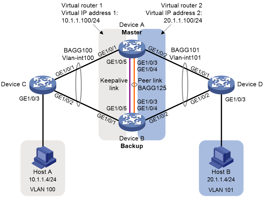
Procedure
1. Configure Device A:
# Configure M-LAG system settings.
<DeviceA> system-view
[DeviceA] m-lag system-mac 1-1-1
[DeviceA] m-lag system-number 1
[DeviceA] m-lag system-priority 123
# Configure M-LAG keepalive parameters.
[DeviceA] m-lag keepalive ip destination 1.1.1.2 source 1.1.1.1
# Set the link mode of GigabitEthernet 1/0/5 to Layer 3, and assign the interface an IP address. The IP address will be used as the source IP address of keepalive packets.
[DeviceA] interface gigabitethernet 1/0/5
[DeviceA-GigabitEthernet1/0/5] port link-mode route
[DeviceA-GigabitEthernet1/0/5] ip address 1.1.1.1 24
[DeviceA-GigabitEthernet1/0/5] quit
# Exclude the interface used for M-LAG keepalive detection (GigabitEthernet 1/0/5) from the shutdown action by M-LAG MAD.
[DeviceA] m-lag mad exclude interface gigabitethernet 1/0/5
# Create Layer 2 dynamic aggregate interface Bridge-Aggregation 125.
[DeviceA] interface bridge-aggregation 125
[DeviceA-Bridge-Aggregation125] link-aggregation mode dynamic
[DeviceA-Bridge-Aggregation125] quit
# Assign GigabitEthernet 1/0/3 and GigabitEthernet 1/0/4 to aggregation group 125.
[DeviceA] interface gigabitethernet 1/0/3
[DeviceA-GigabitEthernet1/0/3] port link-aggregation group 125
[DeviceA-GigabitEthernet1/0/3] quit
[DeviceA] interface GigabitEthernet 1/0/4
[DeviceA-GigabitEthernet1/0/4] port link-aggregation group 125
[DeviceA-GigabitEthernet1/0/4] quit
# Specify Bridge-Aggregation 125 as the peer-link interface.
[DeviceA] interface bridge-aggregation 125
[DeviceA-Bridge-Aggregation125] port m-lag peer-link 1
[DeviceA-Bridge-Aggregation125] quit
# Create Layer 2 dynamic aggregate interface Bridge-Aggregation 100, and assign it to M-LAG group 1.
[DeviceA] interface bridge-aggregation 100
[DeviceA-Bridge-Aggregation100] link-aggregation mode dynamic
[DeviceA-Bridge-Aggregation100] port m-lag group 1
[DeviceA-Bridge-Aggregation100] quit
# Assign GigabitEthernet 1/0/1 to aggregation group 100.
[DeviceA] interface gigabitethernet 1/0/1
[DeviceA-GigabitEthernet1/0/1] port link-aggregation group 100
[DeviceA-GigabitEthernet1/0/1] quit
# Create Layer 2 dynamic aggregate interface Bridge-Aggregation 101, and assign it to M-LAG group 2.
[DeviceA] interface bridge-aggregation 101
[DeviceA-Bridge-Aggregation101] link-aggregation mode dynamic
[DeviceA-Bridge-Aggregation101] port m-lag group 2
[DeviceA-Bridge-Aggregation101] quit
# Assign GigabitEthernet 1/0/2 to aggregation group 101.
[DeviceA] interface gigabitethernet 1/0/2
[DeviceA-GigabitEthernet1/0/2] port link-aggregation group 101
[DeviceA-GigabitEthernet1/0/2] quit
# Create VLAN 100 and VLAN 101.
[DeviceA] vlan 100
[DeviceA-vlan100] quit
[DeviceA] vlan 101
[DeviceA-vlan101] quit
# Set the link type of Bridge-Aggregation 100 to trunk, and assign it to VLAN 100.
[DeviceA] interface bridge-aggregation 100
[DeviceA-Bridge-Aggregation100] port link-type trunk
[DeviceA-Bridge-Aggregation100] port trunk permit vlan 100
[DeviceA-Bridge-Aggregation100] quit
# Set the link type of Bridge-Aggregation 101 to trunk, and assign it to VLAN 101.
[DeviceA] interface bridge-aggregation 101
[DeviceA-Bridge-Aggregation101] port link-type trunk
[DeviceA-Bridge-Aggregation101] port trunk permit vlan 101
[DeviceA-Bridge-Aggregation101] quit
# Create VLAN-interface 100 and VLAN-interface 101, and assign IP addresses to them.
[DeviceA] interface vlan-interface 100
[DeviceA-vlan-interface100] ip address 10.1.1.1 24
[DeviceA-vlan-interface100] quit
[DeviceA] interface vlan-interface 101
[DeviceA-vlan-interface101] ip address 20.1.1.1 24
[DeviceA-vlan-interface101] quit
# Configure OSPF.
[DeviceA] ospf
[DeviceA-ospf-1] import-route direct
[DeviceA-ospf-1] area 0
[DeviceA-ospf-1-area-0.0.0.0] network 10.1.1.0 0.0.0.255
[DeviceA-ospf-1-area-0.0.0.0] network 20.1.1.0 0.0.0.255
[DeviceA-ospf-1-area-0.0.0.0] quit
[DeviceA-ospf-1] quit
# Create VRRP group 1 on VLAN-interface 100 and set its virtual IP address to 10.1.1.100.
[DeviceA] interface vlan-interface 100
[DeviceA-Vlan-interface100] vrrp vrid 1 virtual-ip 10.1.1.100
# Set the priority of Device A to 200 for it to become the master in VRRP group 1.
[DeviceA-Vlan-interface100] vrrp vrid 1 priority 200
[DeviceA-Vlan-interface100] quit
# Create VRRP group 2 on VLAN-interface 101 and set its virtual IP address to 20.1.1.100.
[DeviceA] interface vlan-interface 101
[DeviceA-Vlan-interface101] vrrp vrid 2 virtual-ip 20.1.1.100
# Set the priority of Device A to 200 for it to become the master in VRRP group 2.
[DeviceA-Vlan-interface101] vrrp vrid 2 priority 200
[DeviceA-Vlan-interface101] quit
2. Configure Device B:
# Configure M-LAG system settings.
<DeviceB> system-view
[DeviceB] m-lag system-mac 1-1-1
[DeviceB] m-lag system-number 2
[DeviceB] m-lag system-priority 123
# Configure M-LAG keepalive parameters.
[DeviceB] m-lag keepalive ip destination 1.1.1.1 source 1.1.1.2
# Set the link mode of GigabitEthernet 1/0/5 to Layer 3, and assign the interface an IP address. The IP address will be used as the source IP address of keepalive packets.
[DeviceB] interface gigabitethernet 1/0/5
[DeviceB-GigabitEthernet1/0/5] port link-mode route
[DeviceB-GigabitEthernet1/0/5] ip address 1.1.1.2 24
[DeviceB-GigabitEthernet1/0/5] quit
# Exclude the interface used for M-LAG keepalive detection (GigabitEthernet 1/0/5) from the shutdown action by M-LAG MAD.
[DeviceB] m-lag mad exclude interface gigabitethernet 1/0/5
# Create Layer 2 dynamic aggregate interface Bridge-Aggregation 125.
[DeviceB] interface bridge-aggregation 125
[DeviceB-Bridge-Aggregation125] link-aggregation mode dynamic
[DeviceB-Bridge-Aggregation125] quit
# Assign GigabitEthernet 1/0/3 and GigabitEthernet 1/0/4 to aggregation group 125.
[DeviceB] interface gigabitethernet 1/0/3
[DeviceB-GigabitEthernet1/0/3] port link-aggregation group 125
[DeviceB-GigabitEthernet1/0/3] quit
[DeviceB] interface gigabitethernet 1/0/4
[DeviceB-GigabitEthernet1/0/4] port link-aggregation group 125
[DeviceB-GigabitEthernet1/0/4] quit
# Specify Bridge-Aggregation 125 as the peer-link interface.
[DeviceB] interface bridge-aggregation 125
[DeviceB-Bridge-Aggregation125] port m-lag peer-link 1
[DeviceB-Bridge-Aggregation125] quit
# Create Layer 2 dynamic aggregate interface Bridge-Aggregation 100, and assign it to M-LAG group 1.
[DeviceB] interface bridge-aggregation 100
[DeviceB-Bridge-Aggregation100] link-aggregation mode dynamic
[DeviceB-Bridge-Aggregation100] port m-lag group 1
[DeviceB-Bridge-Aggregation100] quit
# Assign GigabitEthernet 1/0/1 to aggregation group 100.
[DeviceB] interface gigabitethernet 1/0/1
[DeviceB-GigabitEthernet1/0/1] port link-aggregation group 100
[DeviceB-GigabitEthernet1/0/1] quit
# Create Layer 2 dynamic aggregate interface Bridge-Aggregation 101, and assign it to M-LAG group 2.
[DeviceB] interface bridge-aggregation 101
[DeviceB-Bridge-Aggregation101] link-aggregation mode dynamic
[DeviceB-Bridge-Aggregation101] port m-lag group 2
[DeviceB-Bridge-Aggregation101] quit
# Assign GigabitEthernet 1/0/2 to aggregation group 101.
[DeviceB] interface gigabitethernet 1/0/2
[DeviceB-GigabitEthernet1/0/2] port link-aggregation group 101
[DeviceB-GigabitEthernet1/0/2] quit
# Create VLAN 100 and VLAN 101.
[DeviceB] vlan 100
[DeviceB-vlan100] quit
[DeviceB] vlan 101
[DeviceB-vlan101] quit
# Set the link type of Bridge-Aggregation 100 to trunk, and assign it to VLAN 100.
[DeviceB] interface bridge-aggregation 100
[DeviceB-Bridge-Aggregation100] port link-type trunk
[DeviceB-Bridge-Aggregation100] port trunk permit vlan 100
[DeviceB-Bridge-Aggregation100] quit
# Set the link type of Bridge-Aggregation 101 to trunk, and assign it to VLAN 101.
[DeviceB] interface bridge-aggregation 101
[DeviceB-Bridge-Aggregation101] port link-type trunk
[DeviceB-Bridge-Aggregation101] port trunk permit vlan 101
[DeviceB-Bridge-Aggregation101] quit
# Create VLAN-interface 100 and VLAN-interface 101, and assign IP addresses to them.
[DeviceB] interface vlan-interface 100
[DeviceB-vlan-interface100] ip address 10.1.1.2 24
[DeviceB-vlan-interface100] quit
[DeviceB] interface vlan-interface 101
[DeviceB-vlan-interface101] ip address 20.1.1.2 24
[DeviceB-vlan-interface101] quit
# Configure OSPF.
[DeviceB] ospf
[DeviceB-ospf-1] import-route direct
[DeviceB-ospf-1] area 0
[DeviceB-ospf-1-area-0.0.0.0] network 10.1.1.0 0.0.0.255
[DeviceB-ospf-1-area-0.0.0.0] network 20.1.1.0 0.0.0.255
[DeviceB-ospf-1-area-0.0.0.0] quit
[DeviceB-ospf-1] quit
# Create VRRP group 1 on VLAN-interface 100 and set its virtual IP address to 10.1.1.100.
[DeviceB] interface vlan-interface 100
[DeviceB-Vlan-interface100] vrrp vrid 1 virtual-ip 10.1.1.100
[DeviceB-Vlan-interface100] quit
# Create VRRP group 2 on VLAN-interface 101 and set its virtual IP address to 20.1.1.100.
[DeviceB] interface vlan-interface 101
[DeviceB-Vlan-interface101] vrrp vrid 2 virtual-ip 20.1.1.100
[DeviceB-Vlan-interface101] quit
3. Configure Device C:
# Create Layer 2 dynamic aggregate interface Bridge-Aggregation 100.
<DeviceC> system-view
[DeviceC] interface bridge-aggregation 100
[DeviceC-Bridge-Aggregation100] link-aggregation mode dynamic
[DeviceC-Bridge-Aggregation100] quit
# Assign GigabitEthernet 1/0/1 and GigabitEthernet 1/0/2 to aggregation group 100.
[DeviceC] interface range gigabitethernet 1/0/1 to gigabitethernet 1/0/2
[DeviceC-if-range] port link-aggregation group 100
[DeviceC-if-range] quit
# Create VLAN 100.
[DeviceC] vlan 100
[DeviceC-vlan100] quit
# Set the link type of Bridge-Aggregation 100 to trunk, and assign it to VLAN 100.
[DeviceC] interface bridge-aggregation 100
[DeviceC-Bridge-Aggregation100] port link-type trunk
[DeviceC-Bridge-Aggregation100] port trunk permit vlan 100
[DeviceC-Bridge-Aggregation100] quit
# Set the link type of GigabitEthernet 1/0/3 to trunk, and assign it to VLAN 100.
[DeviceC] interface gigabitethernet 1/0/3
[DeviceC-GigabitEthernet1/0/3] port link-type trunk
[DeviceC-GigabitEthernet1/0/3] port trunk permit vlan 100
[DeviceC-GigabitEthernet1/0/3] quit
# Create VLAN-interface 100, and assign it an IP address.
[DeviceC] interface vlan-interface 100
[DeviceC-vlan-interface100] ip address 10.1.1.3 24
[DeviceC-vlan-interface100] quit
# Configure OSPF.
[DeviceC] ospf
[DeviceC-ospf-1] import-route direct
[DeviceC-ospf-1] area 0
[DeviceC-ospf-1-area-0.0.0.0] network 10.1.1.0 0.0.0.255
[DeviceC-ospf-1-area-0.0.0.0] quit
[DeviceC-ospf-1] quit
4. Configure Device D:
# Create Layer 2 dynamic aggregate interface Bridge-Aggregation 101.
<DeviceD> system-view
[DeviceD] interface bridge-aggregation 101
[DeviceD-Bridge-Aggregation101] link-aggregation mode dynamic
[DeviceD-Bridge-Aggregation101] quit
# Assign GigabitEthernet 1/0/1 and GigabitEthernet 1/0/2 to aggregation group 101.
[DeviceD] interface range gigabitethernet 1/0/1 to gigabitethernet 1/0/2
[DeviceD-if-range] port link-aggregation group 101
[DeviceD-if-range] quit
# Create VLAN 101.
[DeviceD] vlan 101
[DeviceD-vlan101] quit
# Set the link type of Bridge-Aggregation 101 to trunk, and assign it to VLAN 101.
[DeviceD] interface bridge-aggregation 101
[DeviceD-Bridge-Aggregation101] port link-type trunk
[DeviceD-Bridge-Aggregation101] port trunk permit vlan 101
[DeviceD-Bridge-Aggregation101] quit
# Set the link type of GigabitEthernet 1/0/3 to trunk, and assign it to VLAN 101.
[DeviceD] interface gigabitethernet 1/0/3
[DeviceD-GigabitEthernet1/0/3] port link-type trunk
[DeviceD-GigabitEthernet1/0/3] port trunk permit vlan 101
[DeviceD-GigabitEthernet1/0/3] quit
# Create VLAN-interface 101, and assign it an IP address.
[DeviceD] interface vlan-interface 101
[DeviceD-vlan-interface101] ip address 20.1.1.3 24
[DeviceD-vlan-interface101] quit
# Configure OSPF.
[DeviceD] ospf
[DeviceD-ospf-1] import-route direct
[DeviceD-ospf-1] area 0
[DeviceD-ospf-1-area-0.0.0.0] network 20.1.1.0 0.0.0.255
[DeviceD-ospf-1-area-0.0.0.0] quit
[DeviceD-ospf-1] quit
Verifying the configuration
# Verify that Device C has established OSPF neighbor relationships with Device A and Device B.
[DeviceC] display ospf peer
OSPF Process 1 with Router ID 10.1.1.3
Neighbor Brief Information
Area: 0.0.0.0
Router ID Address Pri Dead-Time State Interface
20.1.1.1 10.1.1.1 1 37 Full/DR Vlan100
20.1.1.2 10.1.1.2 1 32 Full/BDR Vlan100
# Verify that Device D has established OSPF neighbor relationships with Device A and Device B.
[DeviceD] display ospf peer
OSPF Process 1 with Router ID 20.1.1.3
Neighbor Brief Information
Area: 0.0.0.0
Router ID Address Pri Dead-Time State Interface
20.1.1.1 20.1.1.1 1 38 Full/DR Vlan101
20.1.1.2 20.1.1.2 1 37 Full/BDR Vlan101
# Verify that Host A and Host B can ping each other. (Details not shown.)
Comparison between M-LAG and DRNI commands
Configuration commands
|
Feature |
View |
M-LAG command |
DRNI command |
|
M-LAG |
Any view |
display m-lag consistency { type1 | type2 } { global | interface interface-type interface-number } |
display drni consistency { type1 | type2 } { global | interface interface-type interface-number } |
|
M-LAG |
Any view |
display m-lag consistency-check status |
display drni consistency-check status |
|
M-LAG |
Any view |
display m-lag drcp statistics [ interface interface-type interface-number ] |
display drni drcp statistics [ interface interface-type interface-number ] |
|
M-LAG |
Any view |
display m-lag keepalive |
display drni keepalive |
|
M-LAG |
Any view |
display m-lag mad verbose |
display drni mad verbose |
|
M-LAG |
Any view |
display m-lag role |
display drni role |
|
M-LAG |
Any view |
display m-lag summary |
display drni summary |
|
M-LAG |
Any view |
display m-lag system |
display drni system |
|
M-LAG |
Any view |
display m-lag troubleshooting [ m-lag-interface | peer-link | keepalive ] [ history ] [ count ] |
display drni troubleshooting [ dr | ipp | keepalive ] [ history ] [ count ] |
|
M-LAG |
Any view |
display m-lag verbose [ interface interface-type interface-number ] |
display drni verbose [ interface interface-type interface-number ] |
|
M-LAG |
Any view |
display m-lag virtual-ip [ interface interface-type interface-number ] |
display drni virtual-ip [ interface interface-type interface-number ] |
|
M-LAG |
System view |
m-lag peer-link mac-address hold undo m-lag peer-link mac-address hold |
drni ipp mac-address hold undo drni ipp mac-address hold |
|
M-LAG |
System view |
m-lag authentication key { simple | cipher } string undo m-lag authentication key |
drni authentication key { simple | cipher } string undo drni authentication key |
|
M-LAG |
System view |
m-lag auto-recovery reload-delay delay-value undo m-lag auto-recovery reload-delay |
drni auto-recovery reload-delay delay-value undo drni auto-recovery reload-delay |
|
M-LAG |
System view |
m-lag consistency-check disable undo m-lag consistency-check disable |
drni consistency-check disable undo drni consistency-check disable |
|
M-LAG |
System view |
m-lag consistency-check mode { loose | strict } undo m-lag consistency-check mode |
drni consistency-check mode { loose | strict } undo drni consistency-check mode |
|
M-LAG |
Layer 2 aggregate interface view or tunnel interface view |
m-lag drcp period short undo m-lag drcp period |
drni drcp period short undo drni drcp period |
|
M-LAG |
System view |
m-lag peer-link mac-address hold undo m-lag peer-link mac-address hold |
drni ipp mac-address hold undo drni ipp mac-address hold |
|
M-LAG |
System view |
m-lag keepalive { ip | ipv6 } destination { ipv4-address | ipv6-address } [ source { ipv4-address | ipv6-address } | udp-port udp-number | vpn-instance vpn-instance-name ] * undo m-lag keepalive { ip | ipv6 } |
drni keepalive { ip | ipv6 } destination { ipv4-address | ipv6-address } [ source { ipv4-address | ipv6-address } | udp-port udp-number | vpn-instance vpn-instance-name ] * undo drni keepalive { ip | ipv6 } |
|
M-LAG |
System view |
m-lag keepalive hold-time value undo m-lag keepalive hold-time |
drni keepalive hold-time value undo drni keepalive hold-time |
|
M-LAG |
System view |
m-lag keepalive interval interval [ timeout timeout ] undo m-lag keepalive interval |
drni keepalive interval interval [ timeout timeout ] undo drni keepalive interval |
|
M-LAG |
System view |
m-lag mad default-action { down | none } undo m-lag mad default-action |
drni mad default-action { down | none } undo drni mad default-action |
|
M-LAG |
System view |
m-lag mad exclude interface interface-type interface-number undo m-lag mad exclude interface interface-type interface-number |
drni mad exclude interface interface-type interface-number undo drni mad exclude interface interface-type interface-number |
|
M-LAG |
System view |
m-lag mad exclude logical-interfaces undo m-lag mad exclude logical-interfaces |
drni mad exclude logical-interfaces undo drni mad exclude logical-interfaces |
|
M-LAG |
System view |
m-lag mad include interface interface-type interface-number undo m-lag mad include interface interface-type interface-number |
drni mad include interface interface-type interface-number undo drni mad include interface interface-type interface-number |
|
M-LAG |
System view |
m-lag mad persistent undo m-lag mad persistent |
drni mad persistent undo drni mad persistent |
|
M-LAG |
System view |
m-lag mad restore |
drni mad restore |
|
M-LAG |
System view |
m-lag restore-delay value undo m-lag restore-delay |
drni restore-delay value undo drni restore-delay |
|
M-LAG |
System view |
m-lag role priority priority-value undo m-lag role priority |
drni role priority priority-value undo drni role priority |
|
M-LAG |
System view |
m-lag sequence enable undo m-lag sequence enable |
drni sequence enable undo drni sequence enable |
|
M-LAG |
System view |
m-lag standalone enable [ delay delay-time ] undo m-lag standalone enable [ delay ] |
drni standalone enable [ delay delay-time ] undo drni standalone enable [ delay ] |
|
M-LAG |
System view |
m-lag system-mac { bridge-address | mac-address } undo m-lag system-mac |
drni system-mac { bridge-address | mac-address } undo drni system-mac |
|
M-LAG |
System view |
m-lag system-number system-number undo m-lag system-number |
drni system-number system-number undo drni system-number |
|
M-LAG |
System view |
m-lag system-priority priority undo m-lag system-priority |
drni system-priority priority undo drni system-priority |
|
M-LAG |
Layer 2 aggregate interface view |
port m-lag group group-id [ allow-single-member ] undo port m-lag group |
port drni group group-id [ allow-single-member ] undo port drni group |
|
M-LAG |
Layer 2 aggregate interface view or tunnel interface view |
port m-lag peer-link port-id undo port m-lag peer-link |
port drni intra-portal-port port-id undo port drni intra-portal-port |
|
M-LAG |
VLAN interface view |
port m-lag ipv6 virtual-ip ipv6-address { prefix-length [ active | standby ] [ virtual-mac mac-address ] | link-local } undo port m-lag ipv6 virtual-ip [ ipv6-address ] |
port drni ipv6 virtual-ip ipv6-address { prefix-length [ active | standby ] [ virtual-mac mac-address ] | link-local } undo port drni ipv6 virtual-ip [ ipv6-address ] |
|
M-LAG |
Loopback interface view |
port m-lag ipv6 virtual-ip ipv6-address { prefix-length [ active | standby ] | link-local } undo port m-lag ipv6 virtual-ip [ ipv6-address ] |
port drni ipv6 virtual-ip ipv6-address { prefix-length [ active | standby ] [ virtual-mac mac-address ] | link-local } undo port drni ipv6 virtual-ip [ ipv6-address ] |
|
M-LAG |
VLAN interface view |
port m-lag ipv6 virtual-ip ipv6-address { prefix-length [ active | standby ] | link-local } undo port m-lag ipv6 virtual-ip [ ipv6-address ] |
port drni ipv6 virtual-ip ipv6-address { prefix-length [ active | standby ] [ virtual-mac mac-address ] | link-local } undo port drni ipv6 virtual-ip [ ipv6-address ] |
|
M-LAG |
Layer 2 aggregate interface view |
port m-lag system-mac mac-address undo port m-lag system-mac |
port drni system-mac mac-address undo port drni system-mac |
|
M-LAG |
Layer 2 aggregate interface view |
port m-lag system-priority priority undo port m-lag system-priority |
port drni system-priority priority undo port drni system-priority |
|
M-LAG |
VLAN interface view |
port m-lag virtual-ip ipv4-address { mask-length | mask } [ active | standby ] [ virtual-mac mac-address ] undo port m-lag virtual-ip [ ipv4-address ] |
port drni virtual-ip ipv4-address { mask-length | mask } [ active | standby ] [ virtual-mac mac-address ] undo port drni virtual-ip [ ipv4-address ] |
|
M-LAG |
Loopback interface view |
port m-lag virtual-ip ipv4-address { mask-length | mask } [ active | standby ] undo port m-lag virtual-ip [ ipv4-address ] |
port drni virtual-ip ipv4-address { mask-length | mask } [ active | standby ] undo port drni virtual-ip [ ipv4-address ] |
|
M-LAG |
VLAN interface view |
port m-lag virtual-ip ipv4-address { mask-length | mask } [ active | standby ] undo port m-lag virtual-ip [ ipv4-address ] |
port drni virtual-ip ipv4-address { mask-length | mask } [ active | standby ] undo port drni virtual-ip [ ipv4-address ] |
|
M-LAG |
User view |
reset m-lag drcp statistics [ interface interface-list ] |
reset drni drcp statistics [ interface interface-list ] |
|
M-LAG |
User view |
reset m-lag troubleshooting history |
reset drni troubleshooting history |
|
DHCP |
Any view |
display dhcp snooping m-lag-statistics [ old-version ] |
display dhcp snooping drni-statistics [ old-version ] |
|
DHCP |
Any view |
display dhcp snooping m-lag-status |
display dhcp snooping drni-status |
|
DHCP |
User view |
reset dhcp snooping m-lag-statistics |
reset dhcp snooping drni-statistics |
|
DHCPv6 |
Any view |
display ipv6 dhcp snooping m-lag-status |
display ipv6 dhcp snooping drni-status |
|
DHCPv6 |
Any view |
display ipv6 dhcp snooping m-lag-statistics [ old-version ] |
display ipv6 dhcp snooping drni-statistics [ old-version ] |
|
DHCPv6 |
User view |
reset ipv6 dhcp snooping m-lag-statistics |
reset ipv6 dhcp snooping drni-statistics |
|
BGP |
BGP EVPN address family view |
nexthop evpn-m-lag group-address undo nexthop evpn-m-lag group-address |
nexthop evpn-drni group-address undo nexthop evpn-drni group-address |
|
AAA |
RADIUS scheme view |
nas-ip [ m-lag { local | peer } ] { ipv4-address | interface interface-type interface-number | ipv6 ipv6-address } undo nas-ip [ m-lag { local | peer } ] [ interface | ipv6 ] |
nas-ip [ drni { local | peer } ] { ipv4-address | interface interface-type interface-number | ipv6 ipv6-address } undo nas-ip [ drni { local | peer } ] [ interface | ipv6 ] |
|
802.1X |
Any view |
Example commands for centralized devices: display dot1x connection [ open ] [ [ m-lag [ local | peer ] ] [ interface interface-type interface-number | online-type { auth-fail-domain | critical-domain | preauth-domain | success } | user-name name-string ] | user-mac mac-address ] |
Example commands for centralized devices: display dot1x connection [ open ] [ [ drni [ local | peer ] ] [ interface interface-type interface-number | online-type { auth-fail-domain | critical-domain | preauth-domain | success } | user-name name-string ] | user-mac mac-address ] |
|
MAC authentication |
Any view |
Example commands for centralized devices: display mac-authentication connection [ open ] [ [ m-lag [ local | peer ] ] [ interface interface-type interface-number | online-type { auth-fail-domain | critical-domain | preauth-domain | success | url-unavailable-domain } | user-name user-name ] | user-mac mac-address ] |
Example commands for centralized devices: display mac-authentication connection [ open ] [ [ drni [ local | peer ] ] [ interface interface-type interface-number | online-type { auth-fail-domain | critical-domain | preauth-domain | success | url-unavailable-domain } | user-name user-name ] | user-mac mac-address ] |
|
Port security |
System view |
port-security m-lag load-sharing-mode { centralized | distributed { even-mac | local | odd-mac } } undo port-security m-lag load-sharing-mode |
port-security drni load-sharing-mode { centralized | distributed { even-mac | local | odd-mac } } undo port-security drni load-sharing-mode |
|
Port security |
Any view |
Example commands for centralized devices: display port-security static-user connection [ [ m-lag [ local | peer ] ] [ interface interface-type interface-number | online-type { auth-fail-domain | critical-domain | preauth-domain | success } | user-name user-name ] | { ip | ipv6 } ip-address | mac mac-address ] |
Example commands for centralized devices: display port-security static-user connection [ [ drni [ local | peer ] ] [ interface interface-type interface-number | online-type { auth-fail-domain | critical-domain | preauth-domain | success } | user-name user-name ] | { ip | ipv6 } ip-address | mac mac-address ] |
|
Port security |
Any view |
Example commands for centralized devices: display port-security access-user [ m-lag [ local | peer ] ] [ access-type { dot1x | mac-auth | web-auth | static } | domain isp-name | microsegment microsegment-id | online-type { auth-fail-domain | critical-domain | preauth-domain | success | url-unavailable-domain } ] * |
Example commands for centralized devices: display port-security access-user [ drni [ local | peer ] ] [ access-type { dot1x | mac-auth | web-auth | static } | domain isp-name | microsegment microsegment-id | online-type { auth-fail-domain | critical-domain | preauth-domain | success | url-unavailable-domain } ] * |
|
Portal |
System view |
portal m-lag load-sharing-mode { centralized | distributed { even-ip | odd-ip } } undo portal m-lag load-sharing-mode |
portal drni load-sharing-mode { centralized | distributed { even-ip | odd-ip } } undo portal drni load-sharing-mode |
|
Portal |
System view |
portal m-lag traffic backup { interval interval-value | threshold threshold-value } * undo portal m-lag traffic backup |
portal drni traffic backup { interval interval-value | threshold threshold-value } * undo portal drni traffic backup |
|
Web authentication |
Any view |
Example commands for centralized devices: display web-auth user [ m-lag [ local | peer ] ] [ interface interface-type interface-number ] |
Example commands for centralized devices: display web-auth user [ drni [ local | peer ] ] [ interface interface-type interface-number ] |
|
Track |
System view |
track track-entry-number mlag-mad-status undo track track-entry-number |
track track-entry-number drni-mad-status undo track track-entry-number |
|
VXLAN |
System view |
display l2vpn m-lag arp [ local | remote ] [ count | { public-instance | vpn-instance vpn-instance-name } [ count | ip-address ] ] |
display l2vpn drni arp [ local | remote ] [ count | { public-instance | vpn-instance vpn-instance-name } [ count | ip-address ] ] |
|
VXLAN |
System view |
display l2vpn m-lag arp suppression [ local | remote ] [ count | vsi vsi-name [ count | ip-address ] ] |
display l2vpn drni arp suppression [ local | remote ] [ count | vsi vsi-name [ count | ip-address ] ] |
|
VXLAN |
System view |
display l2vpn m-lag mac-address [ local | remote ] [ count | vsi vsi-name [ count | mac-address ] ] |
display l2vpn drni mac-address [ local | remote ] [ count | vsi vsi-name [ count | mac-address ] ] |
|
VXLAN |
System view |
display l2vpn m-lag nd [ local | remote ] [ count | { public-instance | vpn-instance vpn-instance-name } [ ipv6-address | count ] ] |
display l2vpn drni nd [ local | remote ] [ count | { public-instance | vpn-instance vpn-instance-name } [ ipv6-address | count ] ] |
|
VXLAN |
System view |
display l2vpn m-lag nd suppression [ local | remote ] [ count | vsi vsi-name [ ipv6-address | count ] ] |
display l2vpn drni nd suppression [ local | remote ] [ count | vsi vsi-name [ ipv6-address | count ] ] |
|
EVPN |
System view |
display evpn m-lag synchronized-mac [ vsi vsi-name ] [ count ] |
display evpn drni synchronized-mac [ vsi vsi-name ] [ count ] |
|
EVPN |
System view |
evpn m-lag group { virtual-vtep-ipv4 | virtual-vtep-ipv6 } undo evpn m-lag group |
evpn drni group { virtual-vtep-ipv4 | virtual-vtep-ipv6 } undo evpn drni group |
|
EVPN |
System view |
evpn m-lag local { local-ipv4-address remote remote-ipv4-address | local-ipv6-address remote remote-ipv6-address } undo evpn m-lag local |
evpn drni local { local-ipv4-address remote remote-ipv4-address | local-ipv6-address remote remote-ipv6-address } undo evpn drni local |
|
EVPN |
System view |
l2vpn m-lag peer-link ac-match-rule vxlan-mapping undo l2vpn m-lag peer-link ac-match-rule vxlan-mapping |
l2vpn drni peer-link ac-match-rule vxlan-mapping undo l2vpn drni peer-link ac-match-rule vxlan-mapping |
|
EVPN |
System view |
l2vpn m-lag peer-link tunnel { source source-ipv4 destination destination-ipv4 | source source-ipv6 destination destination-ipv6 } undo l2vpn m-lag peer-link tunnel |
l2vpn drni peer-link tunnel { source source-ipv4 destination destination-ipv4 | source source-ipv6 destination destination-ipv6 } undo l2vpn drni peer-link tunnel |
|
EVPN |
BGP EVPN address family view |
nexthop evpn-m-lag group-address undo nexthop evpn-m-lag group-address |
nexthop evpn-drni group-address undo nexthop evpn-drni group-address |
