- Table of Contents
-
- H3C Servers UniSystem Configuration Examples-6W103
- 01-UniSystem Bulk HDM&BIOS Import Configuration Examples
- 02-H3C UniSystem Cloning Installation Configuration Examples
- 03-UniSystem SMTP Configuration Examples
- 04-H3C UniSystem Cluster Creation Configuration Examples
- 05-H3C UniSystem SNMP Configuration Examples
- 06-H3C UniSystem RAID Configuration Examples
- 07-H3C UniSystem Rack Server Deployment Configuration Examples
- 08-UniSystem Bulk Component Update Configuration Examples
- 09-H3C UniSystem Server Inspection Configuration Example
- 10-H3C Unisystem REPO Acquisition and Use Configuration Examples
- 11-H3C UniSystem LDAP Management Configuration Example
- 12-H3C UniSystem Secure Erase Configuration Examples
- 13-H3C UniSystem Intelligent Version Management Configuration Examples
- 14-H3C UniSystem Bulk IP Settings Configuration Examples
- 15-H3C UniSystem Liquid-Cooling System Configuration Examples
- Related Documents
-
| Title | Size | Download |
|---|---|---|
| 15-H3C UniSystem Liquid-Cooling System Configuration Examples | 2.31 MB |
H3C UniSystem
Liquid-Cooling System Configuration Examples
Copyright © 2025 New H3C Technologies Co., Ltd. All rights reserved.
No part of this manual may be reproduced or transmitted in any form or by any means without prior written consent of New H3C Technologies Co., Ltd.
Except for the trademarks of New H3C Technologies Co., Ltd., any trademarks that may be mentioned in this document are the property of their respective owners.
The information in this document is subject to change without notice.
Contents
Example: Configuring a centralized CDU
Incorporating a cold plate-based liquid-cooled server
Associating a device with a cabinet
Viewing the liquid flow diagram
Example: Configuring a distributed CDU
Incorporating a cold plate-based liquid-cooled server
Associating a device with a cabinet
Viewing the liquid flow diagram
Example: Configuring an immersion-cooled CDU
Incorporating an immersion-cooled server
Associating a device with a cabinet
Viewing the liquid flow diagram
Configuring a monitoring template from the Web interface
Configuring a monitoring template in Excel format
Introduction
The H3C cold plate-based liquid-cooling system solution (hereinafter referred to as the liquid-cooling system) uses cold plate-based liquid cooling technology to achieve high cooling efficiency, significantly improving the efficiency and stability of servers. Simultaneously, the system can effectively reduce the cooling power usage effectiveness (PUE), showcasing the green energy-saving advantages of liquid cooling. This solution also helps data centers arrange more servers in a limited space, thus improving overall computational efficiency.
The UniSystem liquid-cooling management system offers comprehensive support and management features, including managing liquid-cooled servers, CDU devices, and liquid-cooled switches. It provides the following features:
· Server management: Supports management of liquid-cooled servers and provides leakage handling strategies to ensure the safe and reliable operation of the liquid cooling system.
· Infrastructure management: Supports management of various types of CDUs, including centralized CDU, distributed CDU, immersion-cooled CDU, liquid cooling rear door, and environmental monitoring system, and supports customizing monitoring templates for comprehensive CDU management.
· Switch management: Supports management of liquid-cooled switches through NETCONF or SSH, ensuring highly efficient management and monitoring.
With the support of UniSystem, users can monitor and manage liquid-cooled servers, CDUs, and liquid-cooled switches uniformly to ensure efficient, safe, stable operation and enhance overall data center efficiency.
Prerequisites
This document is not restricted to specific software or hardware versions. Procedures and information in the examples might be slightly different depending on the software or hardware version of the device.
The configuration examples were created and verified in a lab environment, and all the devices were started with the factory default configuration. When you are working on a live network, make sure you understand the potential impact of every command on your network.
The following information is provided based on the assumption that you have basic knowledge of UniSystem liquid-cooling system management.
Example: Configuring a centralized CDU
Network configuration
Figure 1 shows the network diagram, and Table 1 shows the network configuration.
Figure 1 Centralized CDU networking plan
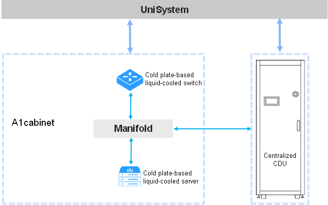
Table 1 Centralized CDU networking information
|
Device role |
Device information |
Description |
|
UniSystem |
UniSystem IP address |
192.168.0.155 |
|
Default UniSystem administrator |
admin |
|
|
Default UniSystem administrator password |
Password@_ |
|
|
Cold plate-based liquid-cooled server |
Device model |
H3C UniServer R4900 G6 |
|
Device IP address |
192.168.20.175 |
|
|
Centralized CDU |
Device name |
Centralized CDU |
|
Device IP address |
192.168.0.154 |
Analysis
1. Log in to UniSystem.
2. Add the data center.
3. Incorporate the cold plate-based liquid-cooled server.
4. Incorporate the CDU.
5. Associate the server with the cabinet.
Software versions used
This configuration example was created and verified on UniSystem-2.65.
Procedures
Logging in to UniSystem
1. Open a browser on the UniSystem client and enter the UniSystem server address.
2. As shown in Figure 2, enter the default username admin and password Password@_ on the login page.
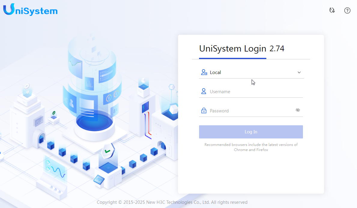
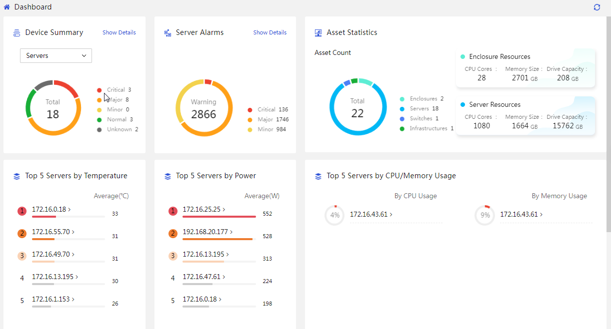
3. Click Log In to access the UniSystem dashboard, as shown in Figure 3.
Adding a data center
|
|
NOTE: Skip this step if you have added the data center, equipment room, and cabinet. |
Adding a data center
1. In the navigation pane, select Menu > Data Center Management > Data Center List.
Figure 4 Data center management
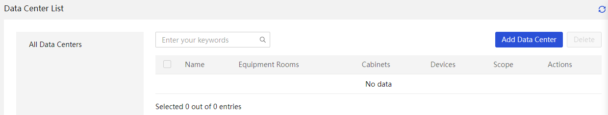
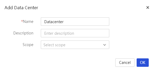
2. Click Add Data Center. In the dialog box that opens, enter the data center name and description.
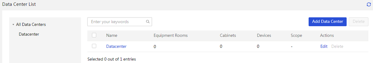
3. After the data center is added successfully, you can view the data center in the list as shown in Figure 6.
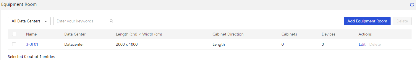
Adding an equipment room
1. In the navigation pane, select Menu > Data Center Management > Equipment Room List.
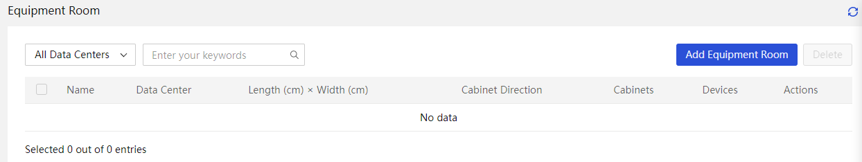
2. Click Add Equipment Room. In the dialog box that opens, enter the equipment room name, description, data center, room size, and cabinet direction.
Figure 8 Adding an equipment room
Table 2 Parameters
|
Parameter |
Description |
|
Name |
Specify the equipment room name, a case-sensitive string of 1 to 30 characters. Only Chinese characters, digits, letters, underscores (_), and hyphens (-) are supported. |
|
Description |
Specify a description for the data center. The description cannot exceed 256 characters and cannot start or end with a space. Only Chinese characters, digits, letters, underscores (_), and spaces are supported. This field is optional. |
|
Data Center |
Specify the name of the data center to which the equipment room belongs. |
|
Room Size |
Specify the length and width of the equipment room. Both the length and width values are in the range of 100 to 9999 in cm. |
|
Cabinet Direction |
Specify the cabinet direction in the equipment room, either lengthwise or widthwise. |
3. After the equipment room is added successfully, you can view the equipment room in the list as shown in Figure 9.

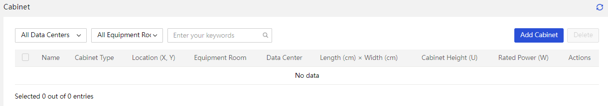
Adding a cabinet
1. In the navigation pane, select Menu > Data Center Management > Cabinet List.
Figure 10 Cabinet list management
2. Click Add Cabinet. In the dialog box that opens, enter the cabinet name, description, data center, cabinet size, and cabinet coordinates.
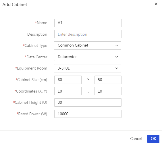
Table 3 Parameters
|
Parameter |
Description |
|
Name |
Specify the cabinet name, a case-sensitive string of 2 to 30 characters. Only Chinese characters, digits, letters, underscores (_), and hyphens (-) are supported. |
|
Description |
Specify a description for the cabinet. The description cannot exceed 256 characters and cannot start or end with a space. Only Chinese characters, digits, letters, underscores (_), and spaces are supported. This field is optional. |
|
Cabinet Type |
Specify the cabinet type. Options include standard cabinet and immersion cabinet (TANK). |
|
Data Center |
Specify the name of the data center to which the cabinet belongs. |
|
Equipment Room |
Specify the name of the equipment room to which the cabinet belongs. |
|
Cabinet Size |
Specify the length and width of the cabinet. Both the length and width values are in the range of 50 to 99 in cm. |
|
Coordinates |
Specify the location of the left corner of the cabinet showed by coordinates, with the room length side as the x-axis and the room width side as the y-axis. |
|
Cabinet Height |
Specify the height of the cabinet, in the range of 10 to 60 RUs. |
|
Rated power |
Specify the rated power of the cabinet, in the range of 5 to 99999 W. |
3. After the cabinet is added successfully, you can view the cabinet in the list as shown in Figure 12.
Incorporating a cold plate-based liquid-cooled server
1. In the navigation pane, select Menu > Devices > Server List.
2. Click Add and select Add Manually.
¡ Select HDM from the Device Type field.
¡ Enter the HDM management IP address of the target server.
¡ Retain the default static group setting.
¡ Enter the username and password of the HDM administrator.
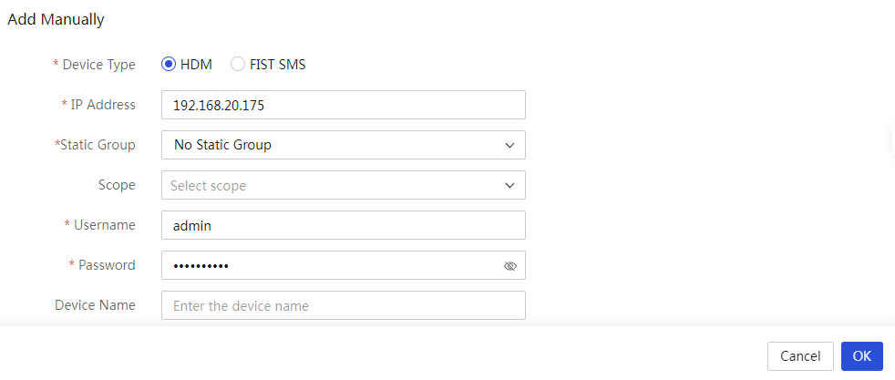
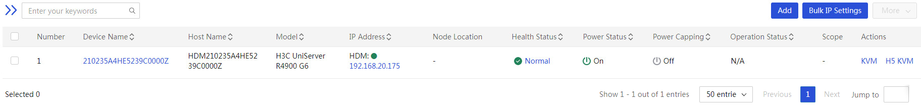
3. After the server is added successfully, you can view the server in the incorporated server list as shown in Figure 14.
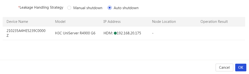
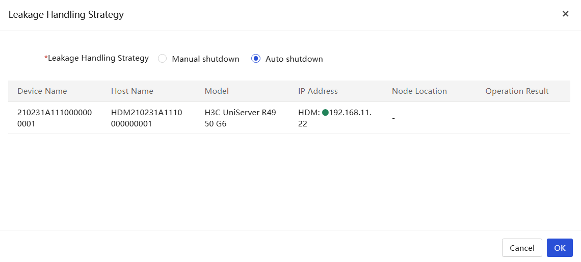
4. To configure the leakage handling strategy, select the target servers, click More, and then select Leakage Handling Strategy. You can select Manual shutdown or Auto shutdown. In this example, auto shutdown is selected.
Figure 15 Leakage handling strategy
Incorporating a CDU
|
|
NOTE: · UniSystem has pre-integrated centralized CDU template ColdPlateCDU. You can directly use this template to manage CDUs that meet the specifications in Table 4. · Device names in the CDU list are case-sensitive must be unique, and the IP address and port combination of each device must also be unique. If you add a device that uses the same IP address and port as an incorporated device, the adding operation fails. · The system supports displaying the liquid flow diagram only for centralized CDUs managed by the built-in template in UniSystem. |
|
Vendor name |
CDU model |
|
Goaland |
CDU300-WW |
|
YXINDATA |
YD-GCDU-300 |
|
AVIC JONHON OPTRONIC Technology |
YLY-300S-002 |
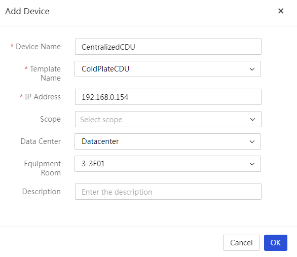
1. In the navigation pane, select Menu > Devices > Infrastructure.
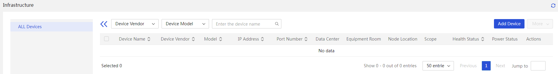
2. Click Add Device, and enter the following information in the dialog box shown in Figure 17.
¡ Enter the device name.
¡ Select the ColdPlateCDU template.
¡ Enter the IP address of the management port on the CDU. In this example, the address is 192.168.0.154. Only IPv4 addresses are supported.
¡ (Optional.) Select the data center and equipment room, and enter the description.
|
Parameter |
Description |
|
Device name |
Specify the CDU name, a case-sensitive string of 1 to 30 characters. Only Chinese characters, digits, letters, underscores (_), and hyphens (-) are supported. |
|
Template name |
Select the monitoring template to be bound to the device. You can configure a monitoring template on the Custom Monitoring Template page. |
|
IP Address |
Enter the IPv4 address of the CDU. Make sure the CDU and the server on which UniSystem is deployed can reach each other. |
|
Data Center |
Select the data center to which the CDU belongs. |
|
Equipment Room |
Select the equipment room to which the CDU belongs. |
|
Description |
Specify a description for the CDU, a case-sensitive string of up to 64 characters. Only Chinese characters, digits, letters, underscores (_), and spaces are allowed. The string cannot start or end with a space. This field is optional. |
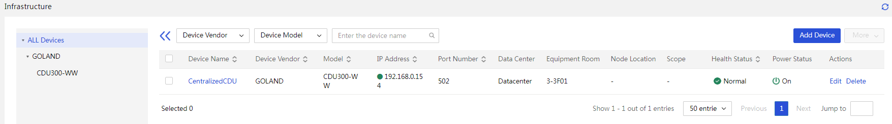
3. Click OK. You can view the added CDU in the CDU list as shown in Figure 18.
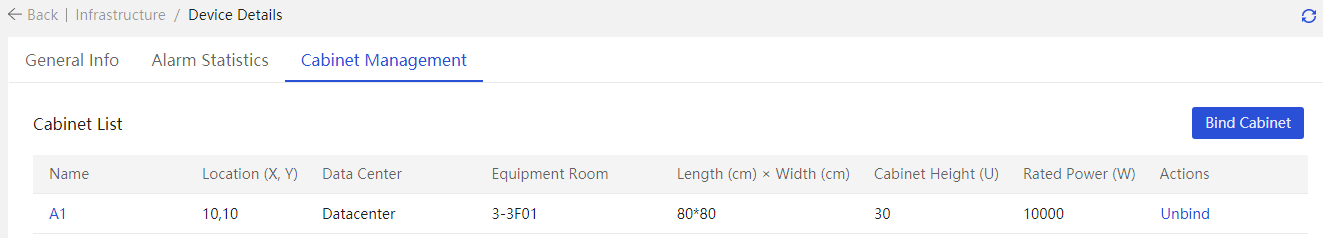
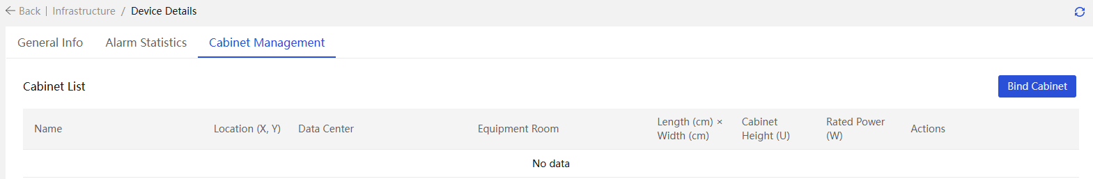
Associating a device with a cabinet
Associating a CDU with a cabinet
|
|
NOTE: · For centralized CDUs, you can only associate the CDUs to common cabinets on the device details page. · Cabinets associated with a centralized CDU cannot associate with other CDUs. |
1. In the navigation pane, select Menu > Devices > Infrastructure.
2. Click the name link of the target device and then click the Cabinet Management tab.
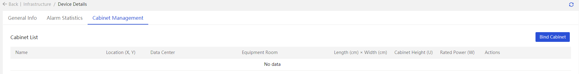
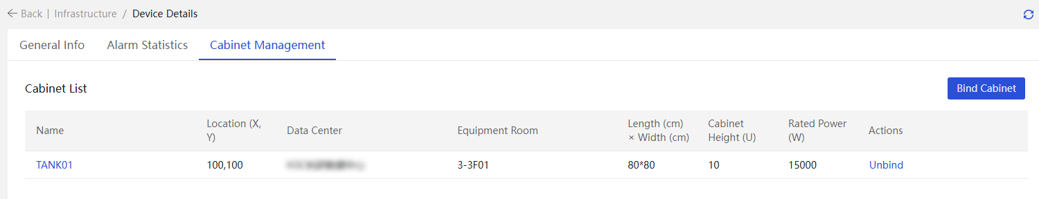
3. Click Bind Cabinet. Select the cabinet associated with the CDU, and then click OK. To unbind the CDU from a cabinet, click Unbind for the cabinet on the Cabinet Management tab.
Figure 20 Associating a device with a cabinet
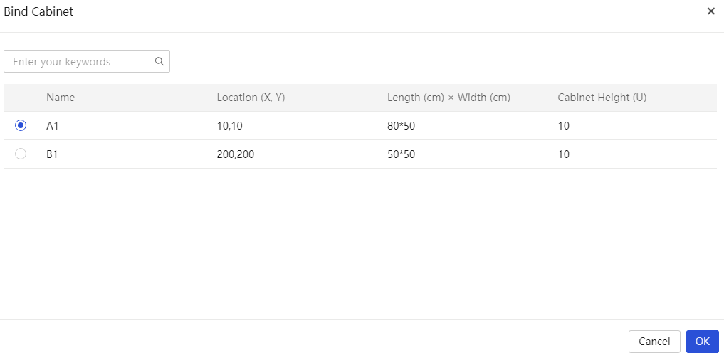
Figure 21 Cabinet management page
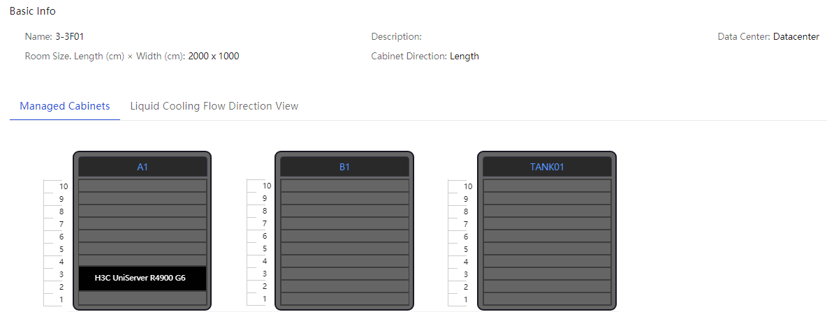
4. To view the cabinet details, click the name link for the target cabinet. The system displays the cabinet usage, basic information, and view of the cabinet by default. To view the temperature details for each device in the cabinet, click Temperature View.
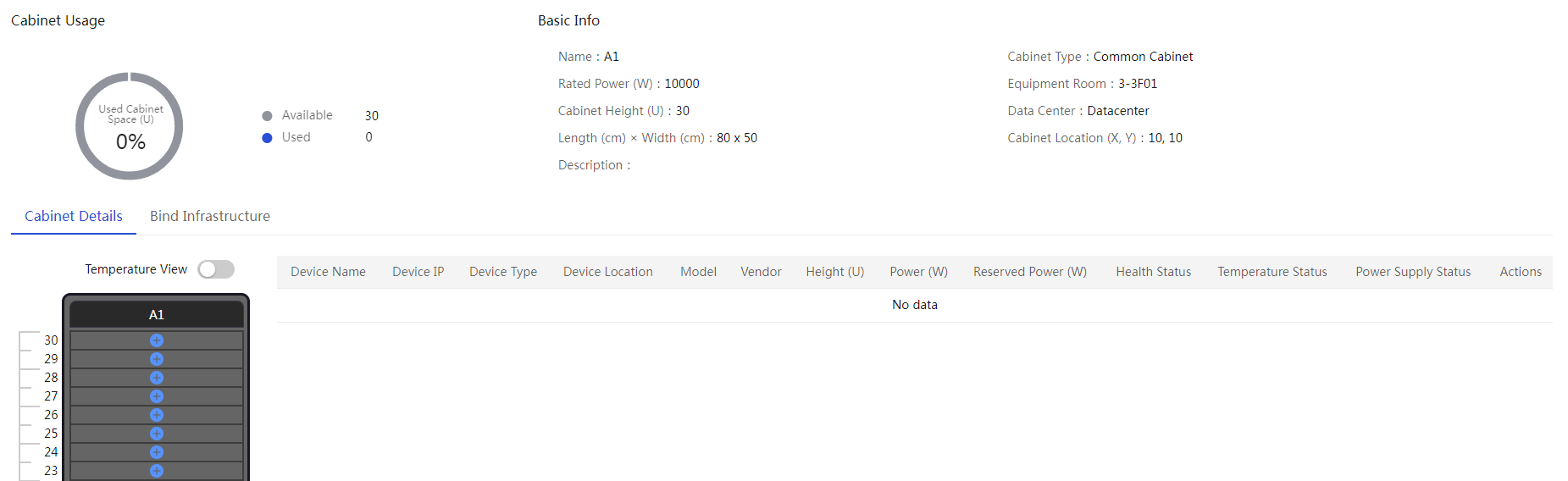
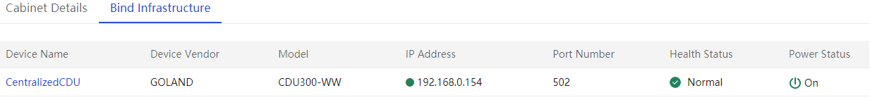
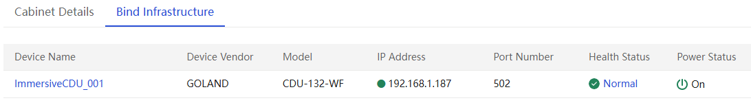
5. To view infrastructures associated with the cabinet, click the Associated Infrastructures tab.
Figure 23 Associated infrastructures
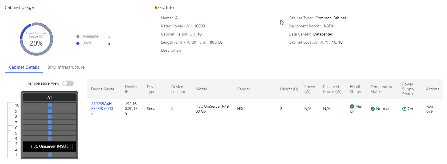
Associating a server with a cabinet
1. Return to the Cabinet Details page as
shown in Figure 22,
and then click the ![]() icon for an empty slot. In the dialog box that opens, select the
target device, and then click OK.
icon for an empty slot. In the dialog box that opens, select the
target device, and then click OK.

2. After the association, the server is displayed in the corresponding slot in the server view, as shown in Figure 25.
Figure 25 Associating a server with a cabinet
Verifying the configuration
Viewing CDU information
1. In the navigation pane, select Menu > Devices > Infrastructure.
2. Click the name link to enter the CDU details page. View the summary and alarm statistics for the CDU.
3. To edit the sensor settings, such as the
secondary supply temperature setpoint, click the ![]() icon to the right of Secondary Side Parameters. The
operation is available only when the module contains readable and writable
sensors.
icon to the right of Secondary Side Parameters. The
operation is available only when the module contains readable and writable
sensors.
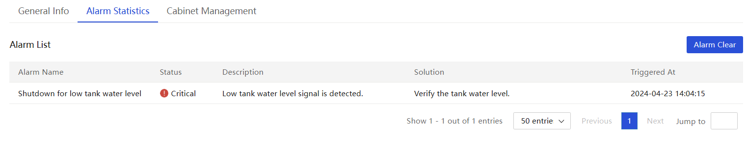
4. Click the Alarm Statistics tab, and view the alarm information detected by sensors.
Viewing the liquid flow diagram
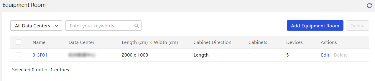
1. In the navigation pane, select Menu > Data Center Management > Equipment Room List.
Figure 26 Equipment room summary information
2. Click the name link of the equipment room and view its details.
Figure 27 Equipment room details
3. Click the Liquid Flow Diagram tab and view the liquid flow information.
Example: Configuring a distributed CDU
Network configuration
Figure 28 shows the network diagram, and Table 6 shows the network configuration.
Figure 28 Distributed CDU networking plan
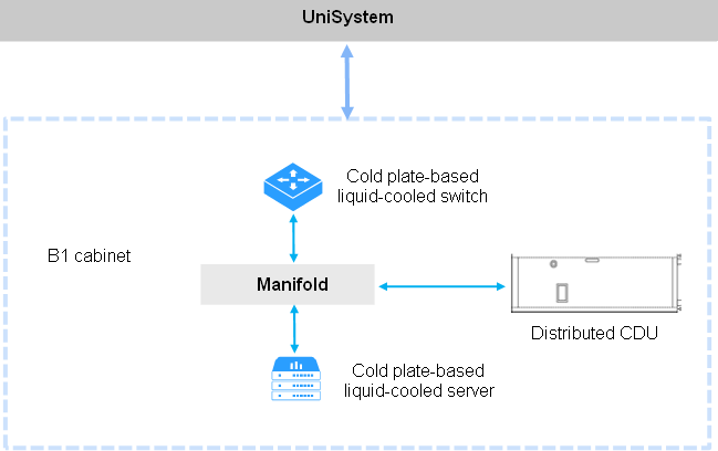
Table 6 Distributed CDU networking information
|
Device role |
Device information |
Description |
|
UniSystem |
UniSystem IP address |
192.168.0.155 |
|
Default UniSystem administrator |
admin |
|
|
Default UniSystem administrator password |
Password@_ |
|
|
Cold plate-based liquid-cooled server |
Device model |
H3C UniServer R4900 G6 |
|
Device IP address |
192.168.11.22 |
|
|
Distributed CDU |
Device name |
Distributed CDU |
|
Device IP address |
192.168.0.178 |
Analysis
1. Log in to UniSystem.
2. Add the data center.
3. Incorporate the cold plate-based liquid-cooled server.
4. Incorporate the CDU.
5. Associate the server with the cabinet.
Software versions used
This configuration example was created and verified on UniSystem-2.65.
Procedures
Logging in to UniSystem
For more information, see "Logging in to UniSystem."
Adding a data center
For more information, see "Adding a data center."
Incorporating a cold plate-based liquid-cooled server
1. In the navigation pane, select Menu > Devices > Server List.
2. Click Add and select Add Manually, as shown in Figure 29.
¡ Select HDM from the Device Type field.
¡ Enter the HDM management IP address of the target server.
¡ Retain the default static group setting.
¡ Enter the username and password of the HDM administrator.

3. After the server is added successfully, you can view the server in the incorporated server list.
4. To configure the leakage handling strategy, select the target servers, click More, and then select Leakage Handling Strategy. You can select Manual shutdown or Auto shutdown. In this example, auto shutdown is selected.
Figure 30 Leakage handling strategy
Incorporating a CDU
|
|
NOTE: · UniSystem has pre-integrated centralized CDU template CDU5204. You can directly use this template to manage Aavid CDUs with model CDU-AAVID-377431-60KW. · Device names in the CDU list are case-sensitive must be unique, and the IP address and port combination of each device must also be unique. If you add a device that uses the same IP address and port as an incorporated device, the adding operation fails. · The system supports displaying the device details diagram only for CDUs managed by built-in template CDU5204 in UniSystem. |
Adding a CDU
1. In the navigation pane, select Menu > Devices > Infrastructure.
2. Click Add Device, and enter the following information in the dialog box shown in Figure 31.
¡ Enter the device name.
¡ Select template CDU5204.
¡ Enter the IP address of the management port on the CDU. In this example, the address is 192.168.0.178. Only IPv4 addresses are supported.
¡ (Optional.) Select the data center and equipment room, and enter the description.
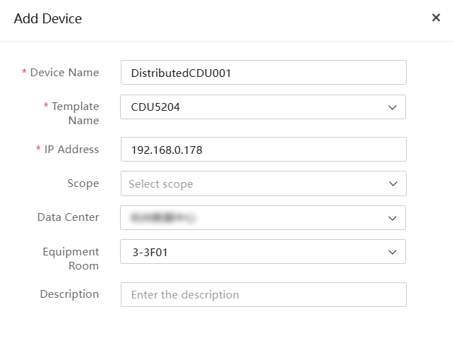
Table 7 Parameters
|
Parameter |
Description |
|
Device name |
Specify the CDU name, a case-sensitive string of 1 to 30 characters. Only Chinese characters, digits, letters, underscores (_), and hyphens (-) are supported. |
|
Template name |
Select the monitoring template to be bound to the device. You can configure a monitoring template on the Custom Monitoring Template page. |
|
IP Address |
Enter the IPv4 address of the CDU. Make sure the CDU and the server on which UniSystem is deployed can reach each other. |
|
Data Center |
Select the data center to which the CDU belongs. |
|
Equipment Room |
Select the equipment room to which the CDU belongs. |
|
Description |
Specify a description for the CDU, a case-sensitive string of up to 64 characters. Only Chinese characters, digits, letters, underscores (_), and spaces are allowed. The string cannot start or end with a space. This field is optional. |
3. Click OK. You can view the added CDU in the CDU list.
Associating a device with a cabinet
|
|
NOTE: For distributed CDUs, you can only associate the CDUs to cabinets on the cabinet details page. |
1. In the navigation pane, select Menu > Devices > Infrastructure.
2. Click the name link of the target device and then click the Cabinet Management tab.
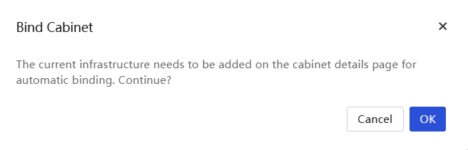
3. Click Bind Cabinet. Select the cabinet associated with the distributed CDU, and then click OK. A dialog box opens as shown in Figure 33, indicating you to access the cabinet details page. Click OK to access the cabinet details page.
Figure 32 Associating a device with a cabinet
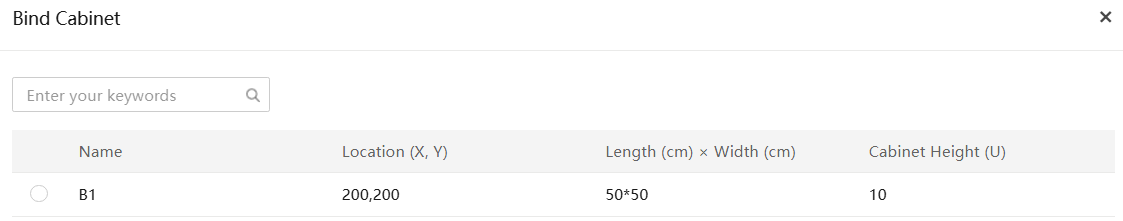
Figure 33 CDU association prompt
4. The cabinet details page displays the cabinet usage, basic information, and view of the cabinet by default. To view the temperature details for each device in the cabinet, click Temperature View.
5. Click the ![]() icon for an empty slot in the cabinet view. Make sure the available
contiguous U space above the selected slot is greater than or equal to the U
space required by the device. In the dialog box that opens as shown in Figure 34,
select the target server and liquid-cooled devices.
icon for an empty slot in the cabinet view. Make sure the available
contiguous U space above the selected slot is greater than or equal to the U
space required by the device. In the dialog box that opens as shown in Figure 34,
select the target server and liquid-cooled devices.
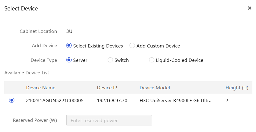
¡ To associate a server, select Server as the device type, and then select the target device. In this example, the server address is 192.168.11.22.
Figure 34 Associating a server with the cabinet
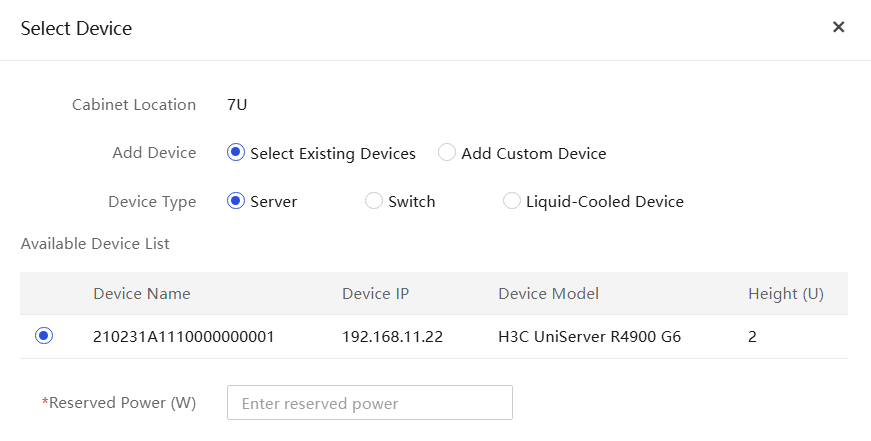
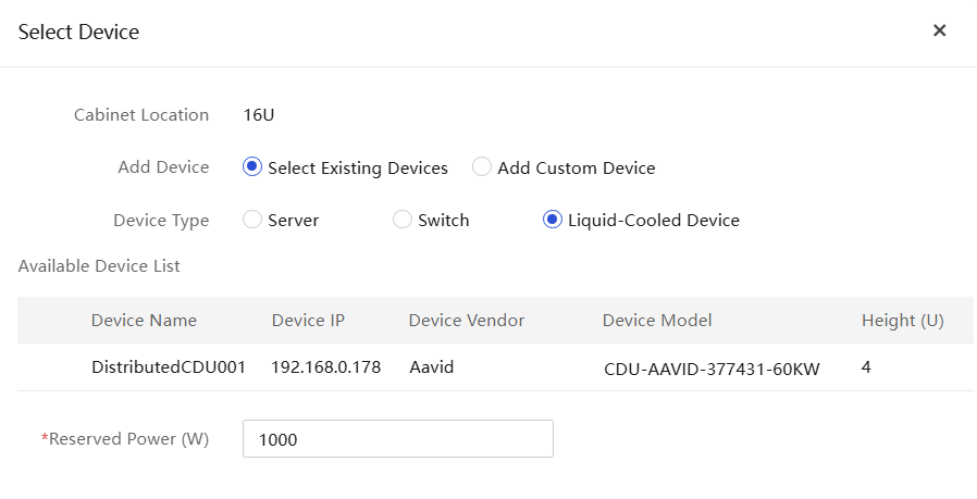
¡ To associate a CDU, select Liquid-Cooled Device as the device type, and then select the target distributed CDU, and set the reserved power.
Figure 35 Associating a CDU device with the cabinet
6. After the association, the server and CDU are displayed in the corresponding slots in the server view, as shown in Figure 1. To view the infrastructures associated with the cabinet, click the Associated Infrastructures tab.
Parameters
|
Parameter |
Description |
|
Device to Associate |
To incorporate a CDU, select the existing device option. |
|
Device Type |
Select the type of device to be associated. Options include Server and Liquid-Cooled Device. |
|
Available Devices |
Devices that can be associated with the cabinet. Make sure the available contiguous U space above the selected slot is greater than or equal to the U space required by the device to be associated. |
|
Reserved Power |
Specify the reserved power required by the device to be associated. Make sure the reserved power does not exceed the remaining rated power of the cabinet. |
Verifying the configuration
Viewing CDU information
1. In the navigation pane, select Menu > Devices > Infrastructure.
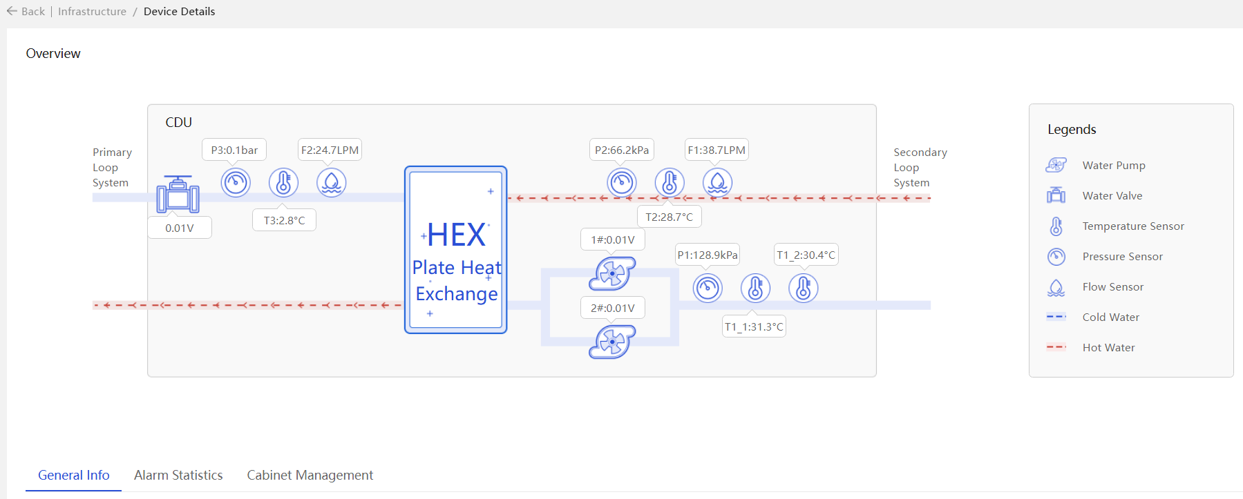
2. Click the name link to enter the CDU details page. View the summary figure, overview, and alarm statistics for the CDU, as shown in Figure 36.
3. To edit the sensor settings, such as the
pump mode, click the ![]() icon to the right of Others on the Overview tab. The
operation is available only when the module contains readable and writable
sensors.
icon to the right of Others on the Overview tab. The
operation is available only when the module contains readable and writable
sensors.
Figure 37 Editing CDU sensor parameters

4. Click the Alarm Statistics tab, and view the alarm information detected by sensors.
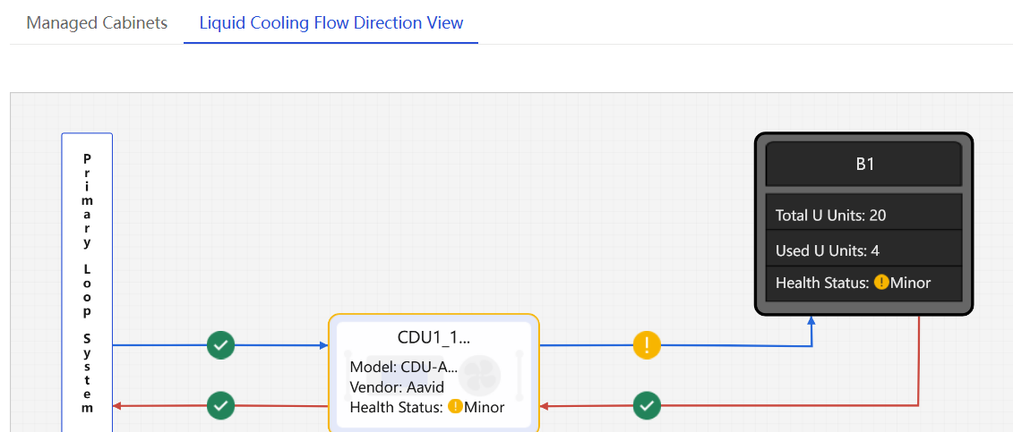
Viewing the liquid flow diagram
1. In the navigation pane, select Menu > Data Center Management > Equipment Room.
Figure 39 Equipment room summary information
2. Click the name link of the equipment room and view its details.
3. Click the Liquid Cooling Flow Direction View tab and view the liquid flow information.
Example: Configuring an immersion-cooled CDU
Network configuration
Figure 7 shows the network diagram, and Table 8 shows the network configuration.
Figure 41 Immersion-cooled CDU networking plan
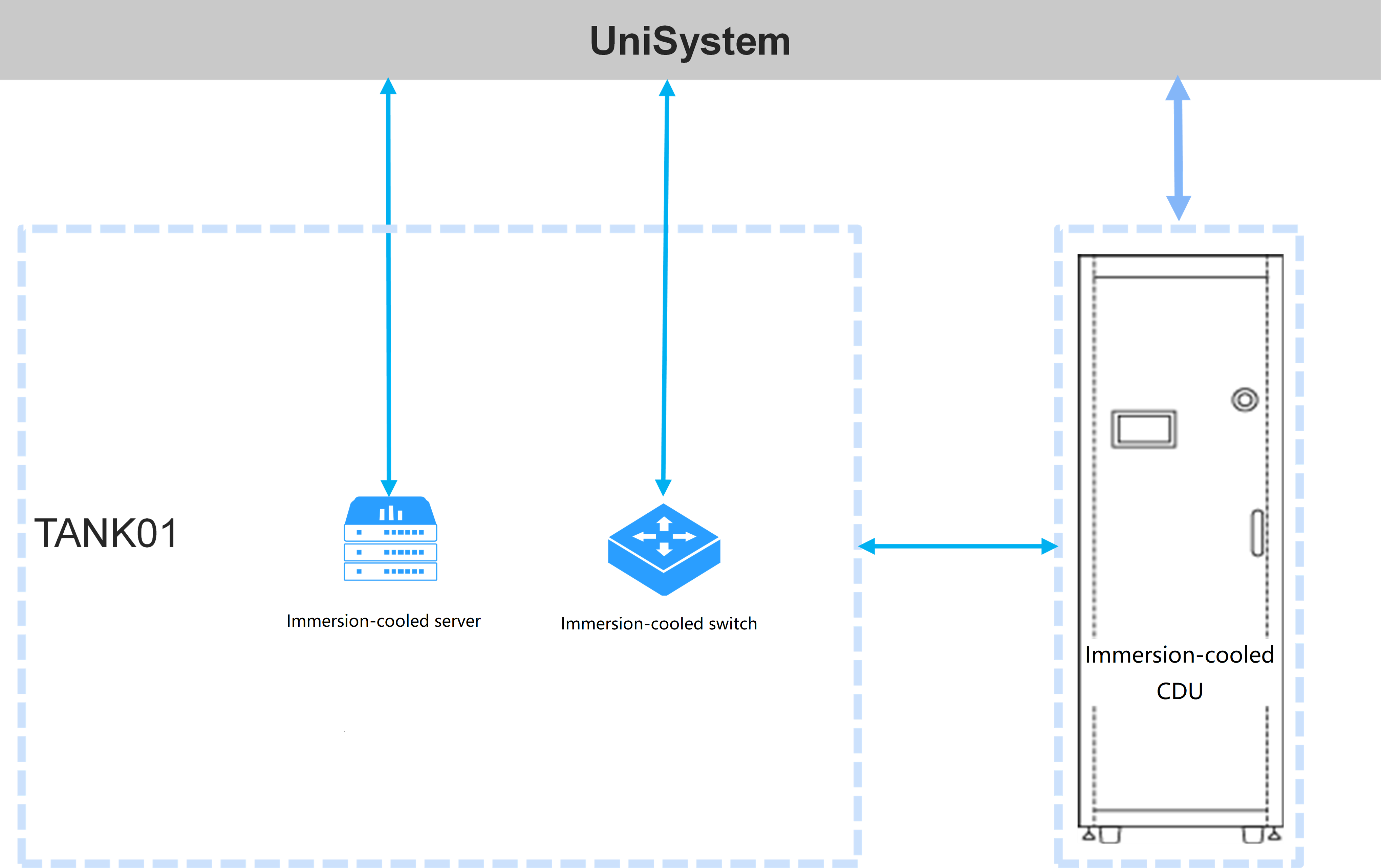
Table 8 Immersion-cooled CDU networking information
|
Device role |
Device information |
Description |
|
UniSystem |
UniSystem IP address |
192.168.0.155 |
|
Default UniSystem administrator |
admin |
|
|
Default UniSystem administrator password |
Password@_ |
|
|
Immersion-cooled server |
Device model |
H3C UniServer R4900LE G6 Ultra |
|
Device IP address |
192.168.97.70 |
|
|
Immersion-cooled CDU |
Device name |
Immersion-cooled CDU |
|
Device IP address |
192.168.0.187 |
Analysis
1. Log in to UniSystem.
2. Add the data center.
3. Incorporate the immersion-cooled server.
4. Incorporate the CDU.
5. Associate the CDU with the cabinet.
Software versions used
This configuration example was created and verified on UniSystem-2.65.
Procedures
Logging in to UniSystem
For more information, see "Logging in to UniSystem."
Adding a data center
For more information, see "Adding a data center."
Incorporating an immersion-cooled server
1. In the navigation pane, select Menu > Devices > Servers.
2. Click Add and select Add Manually, as shown in Figure 8.
¡ Select HDM from the Device Type field.
¡ Enter the HDM management IP address of the target server.
¡ Retain the default static group setting.
¡ Enter the username and password of the HDM administrator.
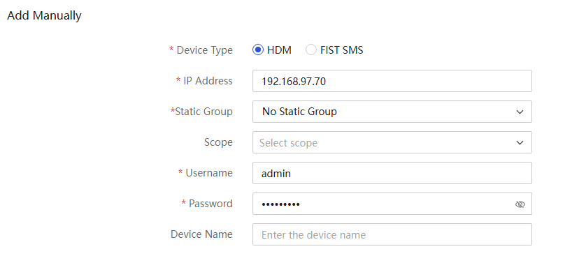
3. After the server is added successfully, you can view the server in the incorporated server list.
Incorporating a CDU
|
|
NOTE: · UniSystem has pre-integrated immersion-cooled CDU template ImmersionCDU. You can directly use this template to manage CDUs that meet the specifications in Table 9. · Device names in the CDU list are case-sensitive must be unique, and the IP address and port combination of each device must also be unique. If you add a device that uses the same IP address and port as an incorporated device, the adding operation fails. · The system supports displaying the liquid flow diagram only for immersion-cooled CDUs managed by the built-in template in UniSystem. |
|
Vendor name |
CDU model |
|
Goaland |
CDU132-WF |
|
CDU180-WF |
|
|
Eco-atlas |
LCE1321BF |
|
LCE1801BF |
|
|
KeenCool |
KCF-C132 |
|
KCF-C180 |
Adding a CDU
1. In the navigation pane, select Menu > Devices > Infrastructure.
2. Click Add Device, and enter the following information in the dialog box shown in Figure 9.
¡ Enter the device name.
¡ Select template ImmersionCDU.
¡ Enter the IP address of the management port on the CDU. In this example, the address is 192.168.0.187. Only IPv4 addresses are supported.
¡ (Optional.) Select the data center and equipment room, and enter the description.
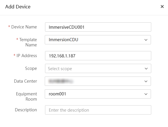
Table 10 Parameters
|
Parameter |
Description |
|
Device name |
Specify the CDU name, a case-sensitive string of 1 to 30 characters. Only Chinese characters, digits, letters, underscores (_), and hyphens (-) are supported. |
|
Template name |
Select the monitoring template to be bound to the device. You can configure a monitoring template on the Custom Monitoring Template page. |
|
IP Address |
Enter the IPv4 address of the CDU. Make sure the CDU and the server on which UniSystem is deployed can reach each other. |
|
Data Center |
Select the data center to which the CDU belongs. |
|
Equipment Room |
Select the equipment room to which the CDU belongs. |
|
Description |
Specify a description for the CDU, a case-sensitive string of up to 64 characters. Only Chinese characters, digits, letters, underscores (_), and spaces are allowed. The string cannot start or end with a space. This field is optional. |
3. Click OK. You can view the added CDU in the CDU list.
Associating a device with a cabinet
|
|
NOTE: For immersion-cooled CDUs, you can only associate the CDUs to cabinets on the device details page. |
Associating a CDU with a cabinet
1. In the navigation pane, select Menu > Devices > Infrastructure.
2. Click the name link of the target device and then click the Cabinet Management tab.
Figure 44 Cabinet management page
3. Click Bind Cabinet. Select the cabinet associated with the CDU, and then click OK. To unbind the CDU from a cabinet, click Unbind for the cabinet on the Cabinet Management tab.
Figure 45 Associating a device with a cabinet
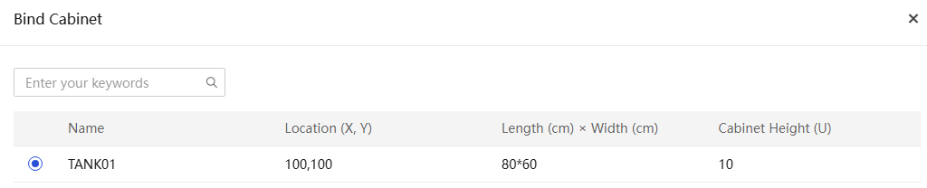
Figure 46 Cabinet management page
4. To view the cabinet details, click the name link for the target cabinet. The system displays the cabinet usage, basic information, and view of the cabinet by default. To view the temperature details for each device in the cabinet, click Temperature View.
5. To view infrastructures associated with the cabinet, click the Associated Infrastructures tab.
Figure 47 Associated infrastructures
Associating a server with a cabinet
1. Return to the Cabinet Details page,
and then click the ![]() icon for an empty slot. In the dialog box that opens, select the
target device, and then click OK.
icon for an empty slot. In the dialog box that opens, select the
target device, and then click OK.
2. After the association, the server is displayed in the corresponding slot in the server view.
Verifying the configuration
View CDU device information
1. In the navigation pane, select Menu > Devices > Infrastructure.
2. Click the name link to enter the CDU details page. View the summary and alarm statistics for the CDU.
3. To edit the sensor settings, such as the
secondary supply return pressure differential setpoint, click the ![]() icon to the right of Secondary Side Parameters. The
operation is available only when the module contains readable and writable
sensors.
icon to the right of Secondary Side Parameters. The
operation is available only when the module contains readable and writable
sensors.
4. Click the Alarm Statistics tab, and view the alarm information detected by sensors.
Viewing the liquid flow diagram
1. In the navigation pane, select Menu > Data Center Management > Equipment Room.
2. Click the name link of the equipment room and view its details.
3. Click the Liquid Flow Diagram tab and view the liquid flow information.
Related documentation
H3C UniSystem Server User Guide
Appendix
Configuring a monitoring template from the Web interface
|
|
NOTE: The custom monitoring template configuration is complex. This section configures typical sensors as an example. For more information, contact Technical Support. |
1. In the navigation pane, select Menu > Devices > Manage Infrastructure > Custom Monitoring Template.
2. To add module names, click Manage Module
Names. In the dialog box that opens, specify the module names, and then
click OK. You can click the ![]() icon to add multiple module names.
icon to add multiple module names.
Figure 49 Managing module names
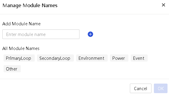
Table 11 Default module name description
|
Default module name |
Description |
|
PrimaryLoop |
The primary loop refers to the circulation of coolant between external heat dissipation facilities (such as cooling towers) and the CDU. |
|
SecondaryLoop |
The secondary loop refers to the circulation of coolant between the CDU and the liquid-cooled device. |
|
Environment |
Environmental parameters, such as temperature and humidity. |
|
Power |
Power parameters, such as the PowerOn, PowerOff, and PowerStatus sensors. |
|
Event |
When a sensor of this type detects an anomaly, the system shows an alarm on the device details page. |
|
Other |
Other parameters. |
3. Click Add Monitoring Template, and configure configure basic information for the template.
|
|
NOTE: Monitoring templates are used to monitor CDUs and the vendor and model in the template must be consistent with the information of the target CDUs. Each device type corresponds to different cabinets. A distributed CDU or environmental monitoring system corresponds to one common cabinet, a centralized CDU can correspond to multiple common cabinets, and an immersion-cooled CDU corresponds to one immersion-cooling cabinet (TANK). |
Figure 50 Adding a monitoring template
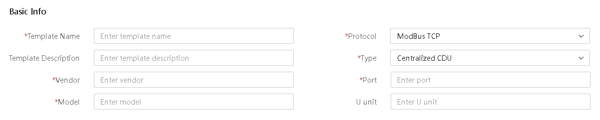
Table 12 Parameters
|
Parameter |
Description |
|
Template name |
Name of the monitoring template. The name is a case-sensitive string of 1 to 30 characters. Only Chinese characters, digits, letters, and underscores (_) are supported. |
|
Template description |
Description of the monitoring template, a case-sensitive string of 0 to 30 characters. The string cannot start or end with a space. Only Chinese characters, digits, letters, underscores (_), and spaces are supported. |
|
Vendor |
Manufacturer of devices to be monitored, a case-sensitive string of 1 to 30 characters. Only Chinese characters, digits, letters, and underscores (_) are supported. |
|
Model |
Model of devices to be monitored, a case-sensitive string of 1 to 30 characters. Only Chinese characters, digits, letters, underscores (_), hyphens (-), and dots (.) are supported. |
|
Protocol |
Protocol used by devices to be monitored. Only the ModBus TCP protocol is supported. |
|
Type |
Type of devices to be monitored. Options include centralized CDU, distributed CDU, immersion-cooled CDU, rear door heat exchanger, environmental monitoring host, and others. |
|
Port number |
Port number of devices to be monitored, in the range of 1 to 65535. |
|
U Unit |
U position of devices to be monitored, an integer in the range of 1 to 100. This field is required for distributed CDUs and environmental monitoring hosts, and is optional for other types of CDUs. |
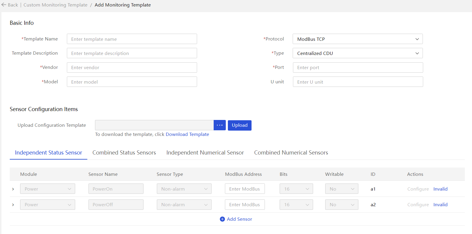
4. In the Sensor Configuration section, click the Independent Status Sensors tab and set the ModBus address of the PowerOn sensor to 00001 and the ModBus address of the PowerOff sensor to 40001.
|
|
NOTE: · Most parameters of the PowerOn and PowerOff sensors displayed by default use fixed values and cannot be modified. You can only specify the ModBus addresses for the two sensors. If the CDU does not have the two sensors, click Invalid to set the sensors to invalid. · To obtain the ModBus address of a sensor, contact the manufacturer of the CDU. |
Figure 51 Independent status sensors
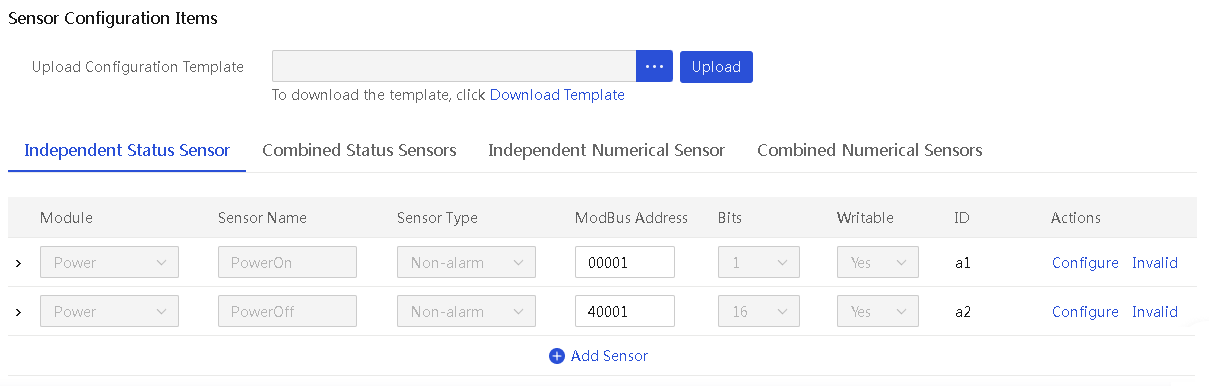
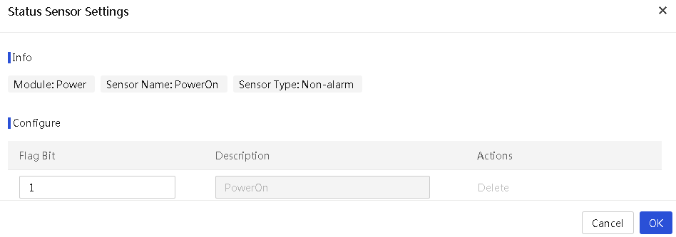
5. Configure the PowerOn sensor. Click Configure for the PowerOn sensor. The ModBus address of the sensor is 00001, which is an address in zone 0 (coil type). Only one flag bit is available and the flag bit value can only be 0 or 1. Set the flag bit to 1, and retain the default description PowerOn. This represents that when a value of 1 is written to the sensor, the system performs a PowerOn operation on the CDU.
|
|
NOTE: Skip this step if the PowerOn sensor is set to invalid. |
Figure 52 Configuring the PowerOn sensor
|
Parameter |
Description |
|
ModBus Address |
ModBus address of the sensor to be added. Both 5-bit and 6-bit addresses are supported. · The 5-bit address must be in the range of 00001-09999, 10001-19999, 30001-39999, or 40001-49999. · The 6-bit address must be in the range of 000001-065536, 100001-165536, 300001-365536, or 400001-465536. · The addresses for PowerOn and PowerOff sensors must be in the range of 00001-09999, 40001-49999, 000001-065536, or 400001-465536. · The first digit of the address represents the zone to which the address belongs. |
|
Flag Bit |
Actual reading represented by the selected valid bits. Only a hexadecimal string and the string other is supported. Flag bits must not be duplicated. When you set the flag bit value to other, it indicates that if the result does not match any other flag bit values, the result will be classified under the other flag bit. · When the Bits field is 1 (indicating a ModBus address in zone 0), the flag bit value can only be 0 or 1. · When the Bits field is 16 (indicating a ModBus address in zone 4) and the Valid Bits value is in the range of 0 to 15, the flag bit value can only be 0, 1, or other. If the Valid Bits value is All, the flag bit value is a hexadecimal number in the range of 0 to FFFF. · Omit the prefix 0x in the Flag Bit field. |
|
Description |
Description of the flag bit to be added, a string in the range of 1 to 200 characters. This field is required. |
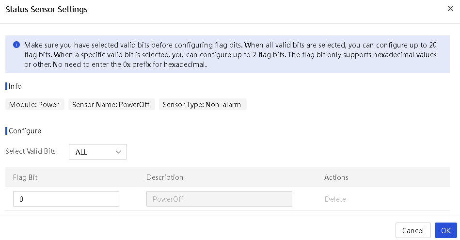
6. Configure the PowerOff sensor. Click Configure for the PowerOff sensor. The ModBus address of the sensor is 40001, which is an address in zone 4 (register type). 16 bits are available and the Valid Bits field is configurable. Select All from the Valid Bits field, set the flag bit value to 1, and retain the default description PowerOff. This represents that when a value of 0 is written to the sensor, the system performs a PowerOff operation on the CDU.
Figure 53 Configuring the PowerOff sensor
|
Parameter |
Description |
|
ModBus Address |
ModBus address of the sensor to be added. Both 5-bit and 6-bit addresses are supported. · The 5-bit address must be in the range of 00001-09999, 10001-19999, 30001-39999, or 40001-49999. · The 6-bit address must be in the range of 000001-065536, 100001-165536, 300001-365536, or 400001-465536. · The addresses for PowerOn and PowerOff sensors must be in the range of 00001-09999, 40001-49999, 000001-065536, or 400001-465536. · The first digit of the address represents the zone to which the address belongs. |
|
Bits |
Bits: Number of bits of the sensor to be added, where 1 bit represents the coil type and 16 bits represent the register type. The number of bits is determined based on the ModBus address of the sensor. Manual input is not required. |
|
Valid Bits |
This field is not available if the Bits value is 1 (representing a ModBus address in zone 0 or zone 1). When the Bits value is 16 (representing a ModBus address in zone 3 or zone 4), you can select All or a value in the range of 0 to 15 from the Valid Bits field. |
|
Flag Bit |
Actual reading represented by the selected valid bits. Only a hexadecimal string and the string other is supported. Flag bits must not be duplicated. When you set the flag bit value to other, it indicates that if the result does not match any other flag bit values, the result will be classified under the other flag bit. · When the Bits field is 1 (indicating a ModBus address in zone 0), the flag bit value can only be 0 or 1. · When the Bits field is 16 (indicating a ModBus address in zone 4) and the Valid Bits value is in the range of 0 to 15, the flag bit value can only be 0, 1, or other. If the Valid Bits value is All, the flag bit value is a hexadecimal number in the range of 0 to FFFF. · Omit the prefix 0x in the Flag Bit field. |
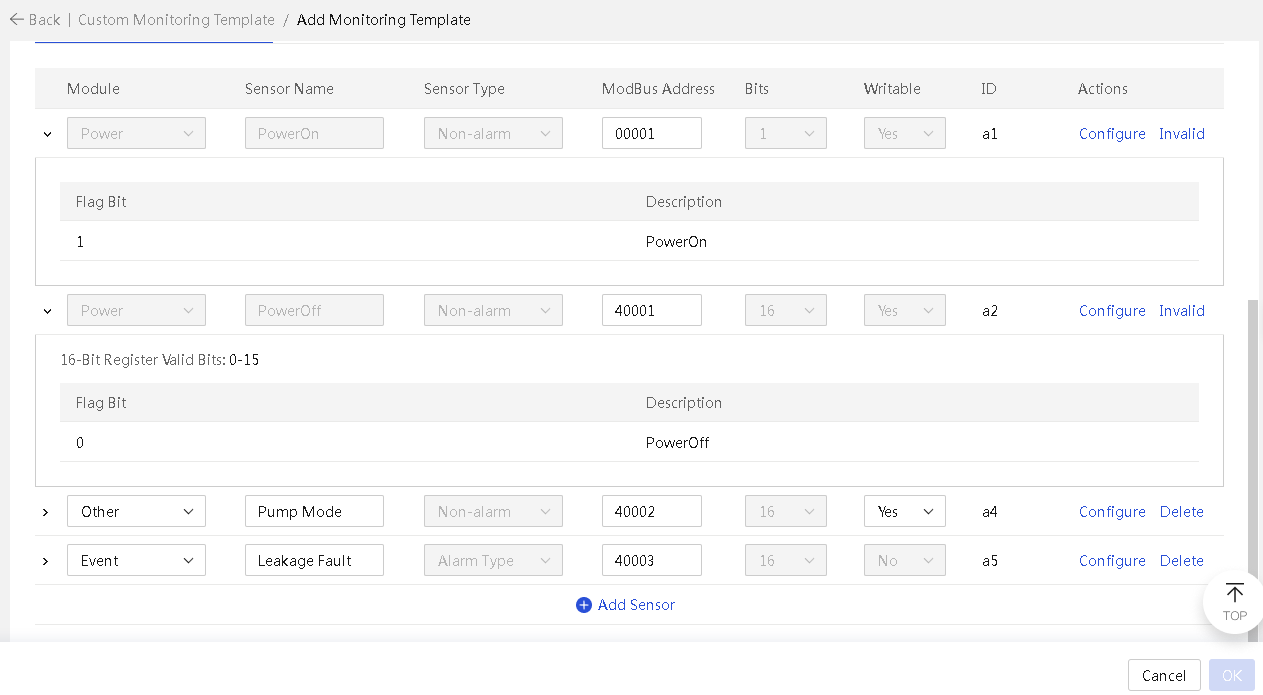
7. To add a sensor, click Add Sensor. This section adds a pump mode sensor as an example.
¡ Select Other from the Module field.
¡ Enter Pump Mode as the sensor name.
¡ The Sensor Type field is automatically set based on the selected module.
¡ Set the ModBus address to 40002.
¡ The Bits field is automatically set to 16 based on the ModBus address.
¡ Set the Writable field to Yes, indicating that the sensor supports value writing.
¡ The ID field is automatically set, which will be used in custom expressions of composite sensors.
8. Repeat the steps to add a leakage fault sensor. Select the Event module, and set the ModBus address to 40003.
Figure 54 Independent status sensors
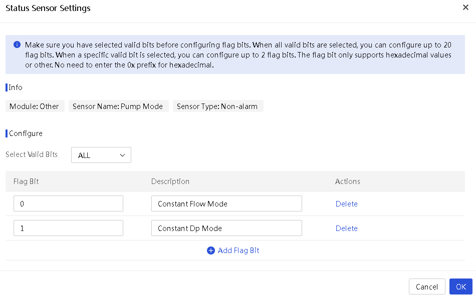
9. Configure the Pump Mode sensor. Click Configure for the sensor. Select 0 from the Valid Bits field, and set the flag bit value to 0 or 1. In this example, the value of 0 represents the constant flow mode and the value of 1 represents the constant dp mode.
Figure 55 Configuring a sensor of the non-alarm type
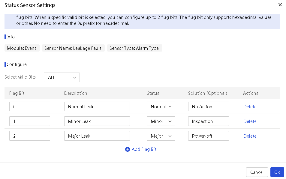
10. Configure the leakage fault sensor. Click Configure for the sensor. Select All from the Valid Bits field, and set values of flat bits. A maximum of 20 flag bits are supported and the value range for each flag bit is in the range of 0 to FFFF. In this example, if the value read by the sensor is 0, it indicates that leakage monitoring is in normal state for the CDU and no action is required. If the value is 1, it indicates a minor leak that requires inspection. If the value is 2, it indicates a severe leak that requires immediate power-off.
Figure 56 Configuring a sensor of the alarm type
|
Parameter |
Description |
|
Module |
Module to which the sensor belongs. Make sure the module has been created. |
|
Sensor name |
Name of the sensor to be added, a case-sensitive string of 1 to 100 characters. The name cannot contain only spaces. |
|
Sensor type |
Type of the sensor, alarm or non-alarm. This field does not require manual configuration. |
|
ModBus Address |
ModBus address of the sensor to be added. Both 5-bit and 6-bit addresses are supported. · The 5-bit address must be in the range of 00001-09999, 10001-19999, 30001-39999, or 40001-49999. · The 6-bit address must be in the range of 000001-065536, 100001-165536, 300001-365536, or 400001-465536. · The addresses for PowerOn and PowerOff sensors must be in the range of 00001-09999, 40001-49999, 000001-065536, or 400001-465536. · The first digit of the address represents the zone to which the address belongs. |
|
Bits |
Bits: Number of bits of the sensor to be added, where 1 bit represents the coil type and 16 bits represent the register type. The number of bits is determined based on the ModBus address of the sensor. Manual input is not required. |
|
Writable |
Indicates whether the sensor value us writable, which is determined by the ModBus address and sensor type. · For a sensor of the alarm type, this field is fixed to No. · For a sensor of the non-alarm type, if the ModBus address is in zone 1 or zone 3, this field is fixed to No. · If the ModBus address is in zone 0 or zone 4, you can set this field to Yes or No. · For non-writable sensors, you cannot enter the sensor values on the device details page. · For writable sensors, you can edit the sensor values on the device details page as needed. |
|
ID |
Identifier of the sensor, which will be used in custom expressions of composite sensors. This field is populated by the system automatically. |
|
Valid Bits |
This field is not available if the Bits value is 1 (representing a ModBus address in zone 0 or zone 1). When the Bits value is 16 (representing a ModBus address in zone 3 or zone 4), you can select All or a value in the range of 0 to 15 from the Valid Bits field. |
|
Flag Bit |
Actual reading represented by the selected valid bits. Only a hexadecimal string and the string other is supported. Flag bits must not be duplicated. When you set the flag bit value to other, it indicates that if the result does not match any other flag bit values, the result will be classified under the other flag bit. · When the Bits field is 1 (indicating a ModBus address in zone 0), the flag bit value can only be 0 or 1. · When the Bits field is 16 (indicating a ModBus address in zone 4) and the Valid Bits value is in the range of 0 to 15, the flag bit value can only be 0, 1, or other. If the Valid Bits value is All, the flag bit value is a hexadecimal number in the range of 0 to FFFF. · Omit the prefix 0x in the Flag Bit field. |
|
Description |
Description of the flag bit to be added, a string in the range of 1 to 200 characters. This field is required. |
|
State |
State of the flag bit to be added. Only normal, minor, major, and critical are supported. This field is available only for alarm sensors. |
|
Solution |
Solution for the condition represented by the flag bit to be added, a string of 0 to 200 characters. This field is available only for alarm sensors and cannot contain only spaces. |
|
|
NOTE: The ModBus TCP protocol supports the following main data types: Boolean type (referred to as coil in the protocol) and 2-byte numerical type (referred to as registers in the protocol). These data are further subdivided based on their read/write properties, forming four storage zones in the ModBus TCP protocol. The addresses of these four storage zones, also referred to as ModBus addresses, start with different digits to indicate their properties: · An address starting with 0 indicates a readable and writable Boolean type. · An address starting with 1 indicates a read-only Boolean type. · An address starting with 3 indicates a read-only numerical type. · An address starting with 4 indicates a readable and writable numeric type. |
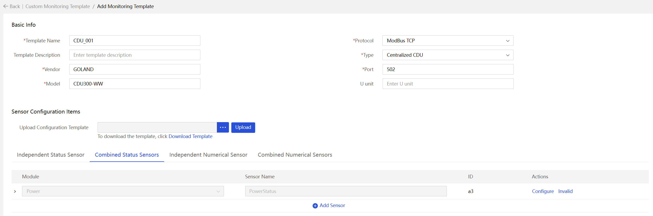
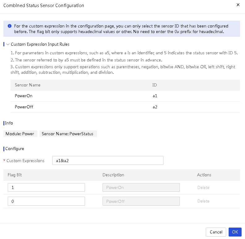
11. Configure composite status sensors. Access the composite status sensor page as shown in Figure 23. By default, a PowerStatus sensor exists. Click Configure for the PowerStatus sensor. In the configuration page that opens, click Custom Expression Input Rule to unfold the relevant filling instructions and the sensor IDs available for the current configuration item, as shown in Figure 24. In the custom expression input box, enter a1&a2, where a1 and a2 represent the PowerOn and PowerOff sensors, respectively. If the reading of the PowerStatus sensor is 1, it indicates the PowerOn state. If the reading of the PowerStatus sensor is 0, it indicates the PowerOff state.
Figure 57 Composite status sensors
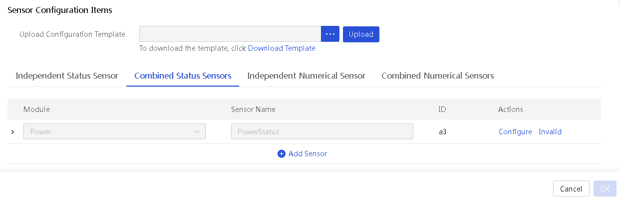
Figure 58 Configuring the PowerStatus sensor
12. To add a composite status sensor, click Add Sensor. Select a module and enter the sensor name. This example adds a running status sensor of the alarm type.
Figure 59 Adding a combined status sensor
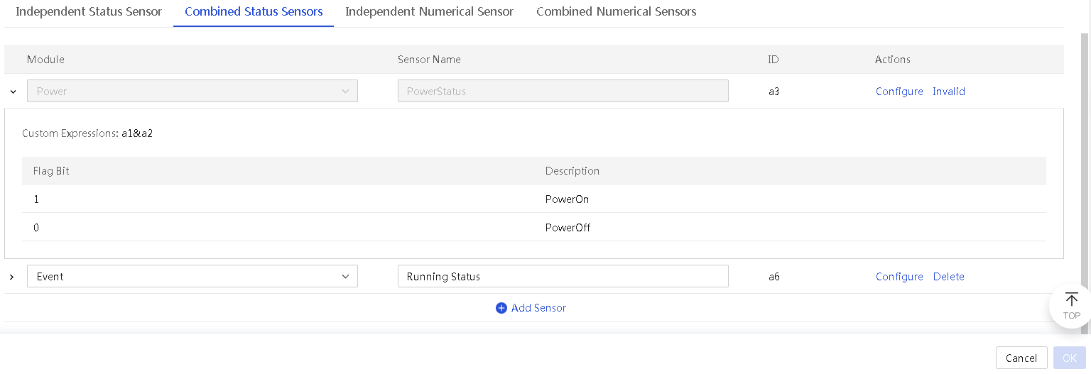
13. Click Configure for the newly added sensor to open the configuration page as shown in Figure 26. Click Custom Expression Input Rule to unfold the relevant filling instructions and the sensor IDs available for the current configuration item. In the custom expression input box, enter a1&(~a5). This indicates the sensor value is the bitwise AND of the a1 sensor value and the inverted a5 sensor value. If the calculated value is 1, it indicates that the CDU is operating normally. If the calculated value is not 1, it indicates that the CDU is in abnormal state.
|
|
NOTE: The PowerOn sensor represented by a1 is in zone 0, and the sensor reading can only be 0 or 1. The leakage fault sensor represented by a5 is in zone 4, and the sensor reading is in the range of 0 to FFFF. Here, if the PowerOn sensor reading is 1 and the leakage fault sensor is in a normal state (represented by value 0), it indicates that the CDU operates normally. Therefore, when the value of a1&(~a5) is 1, it indicates normal operation. |
Figure 60 Configuring a composite status sensor of the alarm type

|
Parameter |
Description |
|
Module |
Module to which the sensor belongs. Make sure the module has been created. In custom device details, all sensors will be categorized under their respective modules. |
|
Sensor name |
Name of the sensor to be added, a case-sensitive string of 1 to 100 characters. The name cannot contain only spaces. |
|
Custom expression |
Expressions for the ID and numerical combination of different state alarm sensors. Only operators () ~ + - * / & | >> << are supported. The expression cannot exceed 120 characters and can contain a maximum of 32 sensor IDs and digits. When you configure custom expressions for composite status sensors, you can use only the IDs of status sensors that have already been configured. |
|
Flag Bit |
Calculation result of the custom expression. Only a hexadecimal string and the string other is supported. Flag bits must not be duplicated. When you set the flag bit value to other, it indicates that if the result does not match any other flag bits, the result will be classified under the other flag bit. Additionally, the other flag bit cannot be selected in the sensor settings on the device details page. Omit the prefix 0x for hexadecimal strings. |
|
Description |
Description of the flag bit to be added, a string in the range of 1 to 200 characters. This field is required. |
|
State |
State of the sensor to be added. Only normal, minor, major, and critical are supported. |
|
Solution |
Solution for the condition represented by the sensor to be added, a string of 0 to 200 characters. This field cannot contain only spaces. |
14. Configure independent numeric sensors. Click the Independent Numeric Sensors tab.
Figure 61 Adding a numerical sensor
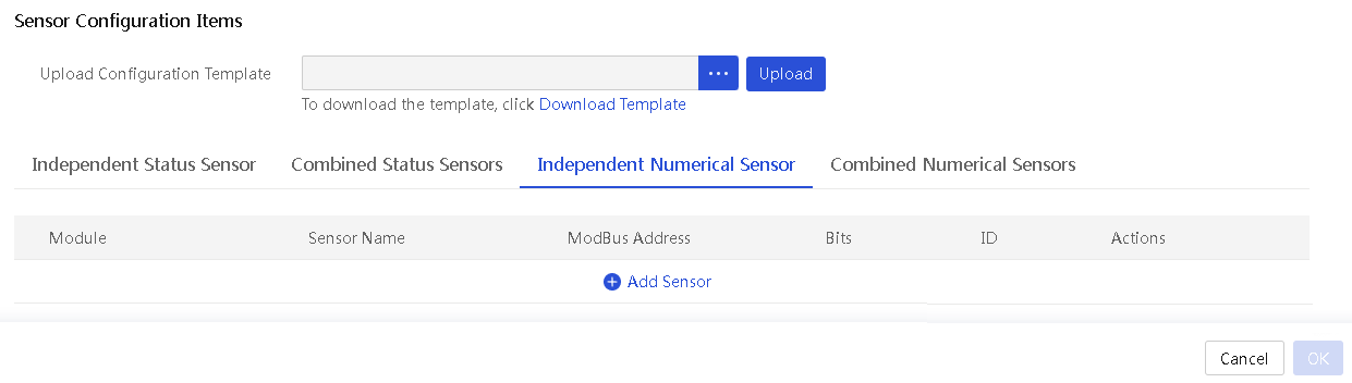
15. Click Add Sensor and add a 16-bit numerical sensor in the dialog box shown in Figure 28.
¡ Select Other from the Module field.
¡ Specify the sensor name. In this example, the sensor name is Water Pump Control Voltage.
¡ Specify the ModBus address as 30005. The address of a numerical sensor can only be in zone 3 or 4.
¡ Select the 16 bits.
¡ Select whether the sensor values support symbols, indicating whether the sensor supports negative values, which affects readout conversion. In this example, No is selected.
¡ Enter the scale factor, which is used to multiply the register read value to get the final number displayed on the CDU device details page.
¡ Set the unit. In this example, the unit is V.
Figure 62 Adding a numerical sensor
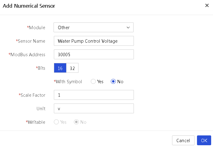
16. Repeat the previous steps and add a 32-bit numerical sensor.
¡ Select Environment from the Module field.
¡ Enter the sensor name. In this example, the sensor name is Ambient temperature.
¡ Enter the ModBus address. In this example, the address is 40005.
¡ Select the 32 bits (occupying two continuous registers).
¡ Select the floating point value type.
¡ Set the decimal precision to 2. This represents the final value precision shown on the CDU details page.
¡ Select the high byte position. If you select Front, it indicates the use of the big-endian order.
¡ Set the scale factor to 1, which is used to multiply the register read value to get the final number displayed on the CDU device details page.
¡ Set the unit to °C.
¡ Select No from the Writable field. This field is configurable only when the ModBus address is in zone 4. If Yes is selected, it indicates that you can edit the sensor values on the CDU device details page.
Figure 63 Adding a numerical sensor
|
Module |
Module to which the sensor belongs. Make sure the module has been created. |
|
Sensor name |
Name of the sensor to be added, a case-sensitive string of 1 to 100 characters. The name cannot contain only spaces. |
|
ModBus Address |
ModBus address of the sensor to be added. Both 5-bit and 6-bit addresses are supported. · The 5-bit address must be in the range of 30001-39999 or 40001-49999. · The 6-bit address must be in the range of 300001-365536 or 400001-465536. |
|
Bits |
Number of bits for the sensor to be added. 16 bits indicate one register, and 32 bits indicate two registers. |
|
Value Type |
· For 16-bit sensors, only the Integer type is supported. · For 32-bit sensors, you can select Integer or Floating Point. |
|
With Symbol |
Whether the value of the sensor to be added is a signed number. This field is available only when the Value Type field is set to Integer. |
|
High Byte Position |
This field is configurable only when the Bits field is 32. It is used indicate the byte order of the two registers. |
|
Scale Factor |
Multiplier to be applied to the value read from the register, in the range of 0 (excluded) to 100 (included). Up to 5 decimal places are supported. |
|
Unit |
Unit for the sensor to be added, a string in the range of 0 to 10 characters. The string cannot contain only spaces. |
|
Writable |
Whether digits can be written to the ModBus address of the sensor. This field is available only when the ModBus address is in the range of 40001-49999 or 400001-465536. |
|
Limit Range |
This field is available only for writable sensors. |
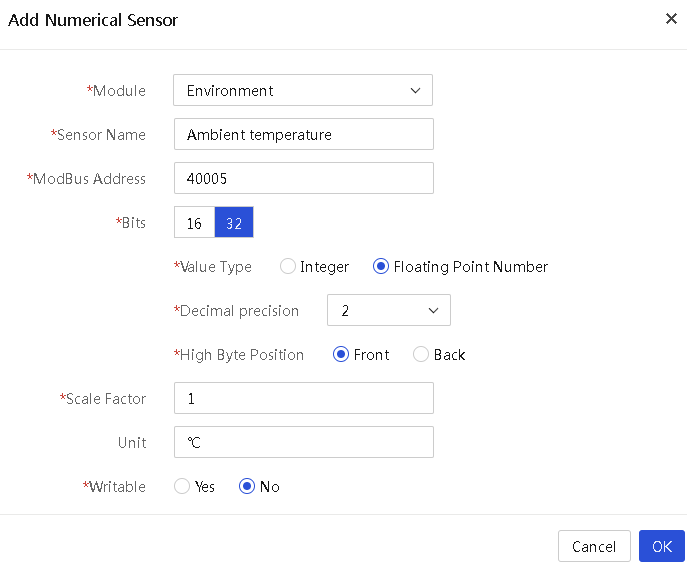
17. Configure composite numerical sensors, click the Composite Numerical Sensors tab, click Add Sensor. This example adds a dew temperature sensor of the Environment module with unit °C and a decimal precision of 1.
Figure 64 Adding a composite numerical sensor
18. Click Configure for the sensor. In the dialog that opens, configure the custom expression. Click Custom Expression Input Rule to unfold the relevant filling instructions and the sensor IDs available for the current configuration item. In this example, the expression is 0.5*a2+10, where a2 represents the ambient temperature sensor reading. The dew temperature is half the ambient temperature plus 10°C.
19. After configuration, click OK. The custom monitoring template is added successfully.
Configuring a monitoring template in Excel format
1. In the navigation pane, select Menu > Devices > Manage Infrastructure > Custom Monitoring Template. Access the Add Monitoring Template page as shown in Figure 31 and download the monitoring template. You can decompress the downloaded package to obtain the .xls template and the .xlsx template.
Figure 65 Downloading the Excel configuration template
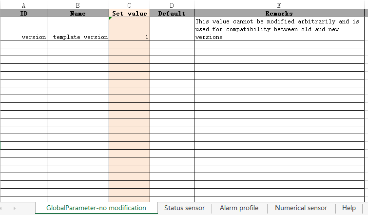
2. Open any downloaded Excel file, as shown in Figure 32. The file includes five worksheets: global parameters, state sensors, alarm meaning, numerical sensors, and help. Leave the global parameters and help worksheets empty.
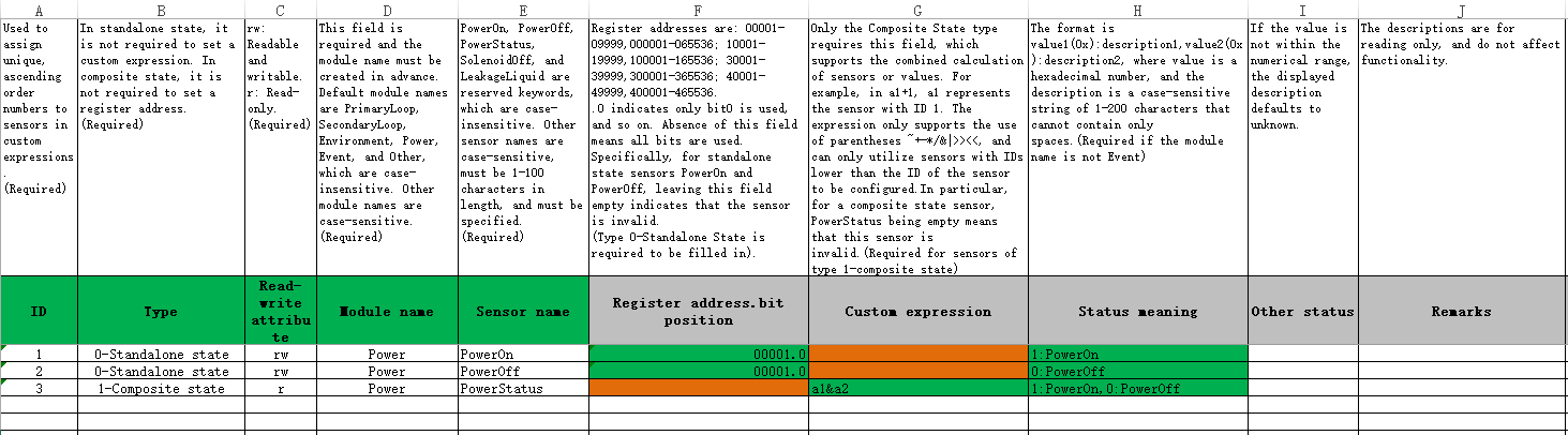
3. Click the state sensors worksheet, as shown in Figure 33. Follow the rules to fill in each cell to configure state sensors. The PowerOn, PowerOff, and PowerStatus sensors are by default fixed in the first three rows. If the CDU device does not support these three sensors, leave the register address.bit position and custom expression fields empty.
¡ For PowerOn and PowerOff sensors, fill in the register address.bit position and the state meaning fields. The PowerOn sensor and PowerOff sensor in the diagram are the same sensor with an address of 00001 and only 1 bit. Therefore, fill in the register address.bit position field with 00001.0 (the dot is followed by the bit position). If the reading of sensor 00001 is 0, the system executes a shutdown (PowerOff) operation on the CDU. If the reading is 1, the system executes a startup (PowerOn) operation.
¡ For the PowerStatus sensor, fill in only the custom expressions and state field. You can set a custom expression for the PowerStatus sensor as a1&a2. When the reading of register 00001 is 0, the value of the expression is 0, indicating a PowerOff state. When the reading is 1, the value is 1, indicating a PowerOn state. Write the state values and their corresponding meanings (descriptions) in the state meaning column, namely 1:PowerOn, 0:PowerOff.
|
|
NOTE: · Given that these three sensors are closely related to the CDU device's on/off functionality, do not modify other parts of the register address and status meaning besides the status values,. If you do so, errors will occur when the template is uploaded. · In the state meaning field, commas (,) and colons (:) do not differ between Chinese and English modes. |
Figure 67 Configuring the status sensor worksheet
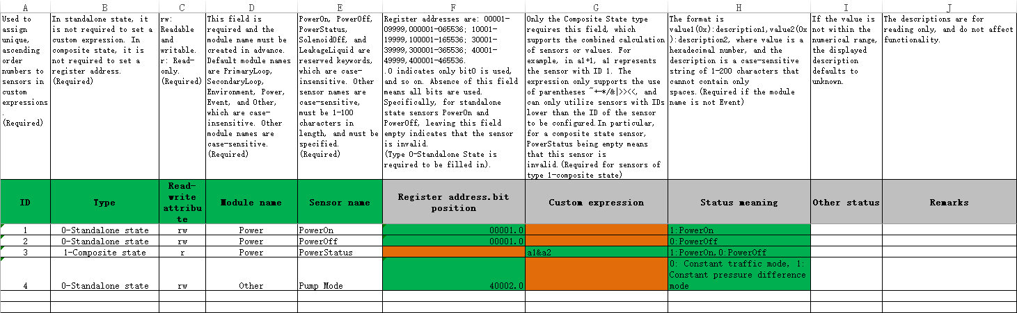
4. As shown in Figure 34, configure the pump mode sensor of the non-alarm type.
¡ Enter 4 in the ID field.
¡ Select the 0-Standalone state.
¡ Select rw (read-write) as the read/writer property.
¡ Select the other module.
¡ Enter Pump Mode as the sensor name.
¡ Enter 40002.0 as the register address.bit position, which represents the 0th bit at address 40002.
¡ Specify the state meaning as 0: Constant traffic mode, 1: Constant pressure difference mode.
Figure 68 Configuring the status sensor worksheet
5. As shown in Figure 35, configure the leak error sensor.
¡ Enter 5 in the ID field.
¡ Select the 0-Standalone state.
¡ Select r (read-only) as the read/writer property.
¡ Select the Event module.
¡ Specify Leak Error as the sensor name.
¡ Enter 40003 as the register address.bit position, which represents all bits at address 40003.
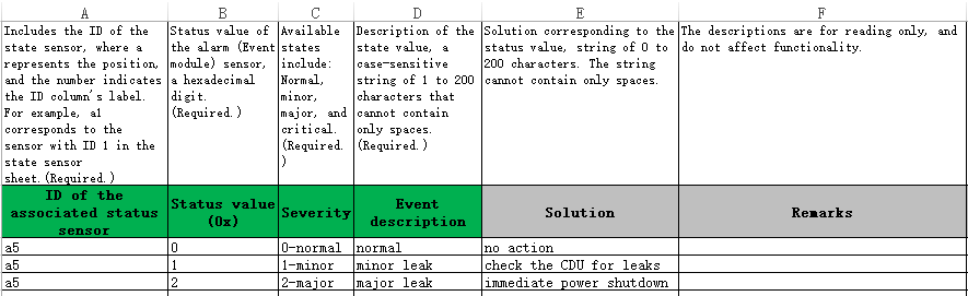
¡ Since its is an alarm-type sensor, you must specify the severity levels in the alarm meaning worksheet. The status meaning and other status fields are not required. Select the alarm meaning worksheet. As shown in Figure 36, enter the alarm meaning for the leak error sensor.
- Enter a5 as the associated sensor ID.
- When the sensor status value is 0, it indicates that the CDU is in normal leak monitoring status and no action is required.
- When the sensor state value is 1, it indicates a minor leak, and you must check the CDU for leaks.
- When the sensor status value is 2, it indicates a severe leak, and immediate power shutdown is required.
Figure 69 Configuring an alarm-type status sensor
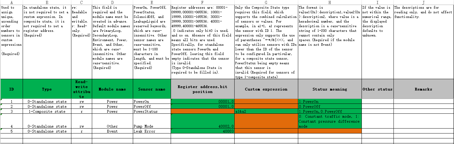
Figure 70 Configuring the alarm meanings for the alarm-type status sensor
6. As shown in Figure 37, configure an alarm-type composite status sensor named Operational status. Non-alarm composite status sensors and non-alarm independent status sensors are similar, but the register address and bit position do not need to be filled out. Specify the custom expressions according to the combination rules.
¡ Enter 6 in the ID field.
¡ Select the 1-Composite state.
¡ Select r (read-only) as the read/write property since the alarm is a composite sensor.
¡ Select the Event module.
¡ Enter Operational status as the sensor name.
¡ Enter custom expression a1-a5. If the calculated result is 1, the state is normal. If the calculated result is not 1, it indicates an anomaly. The rule to determine if the CDU is running normally is that the flag bit of the PowerOn sensor (a1) is set to 1, and the state of the leak error sensor (a5) is normal (flag bit is 0).
¡ Since it is an alarm-type sensor, you must specify the severity levels in the alarm meaning worksheet. The status meaning and other status fields are not required. Select the alarm meaning worksheet. As shown in Figure 38, enter the alarm meaning for the operational status sensor.
- Enter the ID of the associated sensor as a6.
- When the sensor state value is 1, it indicates that the CDU is running normally and requires no processing.
- When the sensor status value is other, it indicates a minor operational anomaly, and the CDU status must be checked.
Figure 71 Configuring an alarm-type composite status sensor
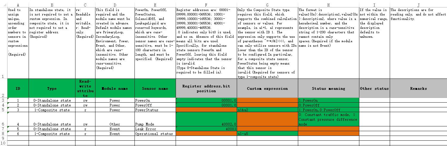
Figure 72 Configuring the alarm meaning for the alarm-type composite status sensor
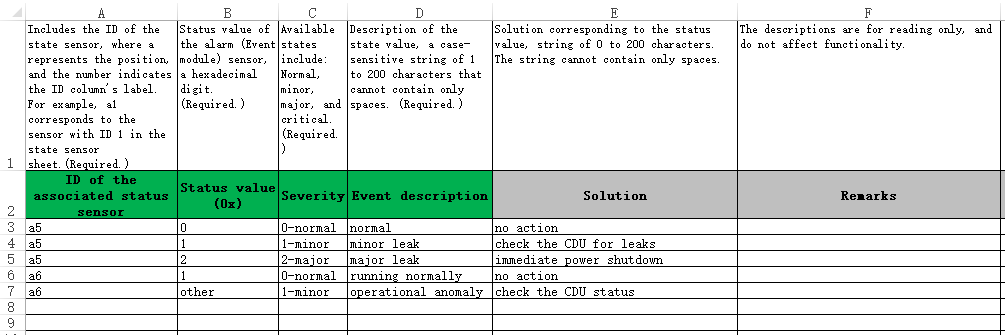
Table 18 Status sensor parameter description
|
Default module name |
Description |
|
ID |
· Sensor ID used in custom expressions. This field is required. · An ID is a positive integer, unique, and arranged in ascending order. · The IDs for the PowerOn, PowerOff, and PowerStatus sensors are permanently set to 1, 2, and 3, respectively. The IDs cannot be changed and the sensors cannot be deleted. |
|
Type |
· Type of the sensor to be configured. This field is required. · Options include 0-Independent state and 1-Composite state, which represent independent state sensors and composite state sensors, respectively. |
|
Read-write attribute |
· Options include rw (read-write) and r (read-only). This field is required. · Composite state sensors support only the r (read-only) type. · For the PowerOn and PowerOff sensors, only the rw (read-write) type is supported. For the PowerStatus sensor, only the r (read-only) type is supported. |
|
Module Name |
· This field is required. Make sure the specified module already exists. · Default module names are PrimaryLoop, SecondaryLoop, Environment, Power, Event, and Other, which are case-insensitive. Other module names are case-sensitive. · The module names for the PowerOn, PowerOff, and PowerStatus sensors are fixed as Power. · The read-write attribute of the Event sensor must be r. |
|
Sensor name |
· The sensor name is required and must be unique. · PowerOn, PowerOff, PowerStatus, SolenoidOff, and LeakageLiquid are reserved keywords, which are case-insensitive. · Other sensor names are case-sensitive, must be 1-100 characters in length, and must be specified. |
|
Register address.bit position |
· When the sensor type is a standalone state, you must fill in this field. Do not fill in this field when the sensor type is composite state. · The register address supports both 5-bit and 6-bit formats. ¡ The 5-bit address must be in the range of 00001-09999, 10001-19999, 30001-39999, or 40001-49999. ¡ The 6-bit address must be in the range of 000001-065536, 100001-165536, 300001-365536, or 400001-465536. · The value after the decimal point in the register address indicates the valid bits, supporting only integers in the range of 0 to 15. For example, .0 means using only bit0. Omitting this field means using all bits. · For independent status sensors PowerOn and PowerOff, if this field is empty, it indicates that the sensor is invalid. · The read-write attribute for addresses in Zone 0 and Zone 4 can be set to r or rw, and the read-write attribute for addresses in Zone 1 and Zone 3 must be r. · Register addresses of the PowerOn and PowerOff sensors are: 00001–09999, 40001–49999, 000001–065536, and 400001–465536. · Excluding PowerOn and PowerOff sensors, when the register address of a standalone status sensor is in Zone 0 or 1, its ModBus address cannot be identical to that of other standalone status sensors. · Excluding PowerOn and PowerOff sensors, when the register address of a standalone status sensor is in Zone 3 or 4, its ModBus address and valid bits cannot be identical to those of other standalone status sensors. · The ModBus address of a standalone status sensor must not duplicate the ModBus address of a standalone numerical sensor. |
|
Custom expression |
· Support combined calculations for sensors or values, such as a1+1, where a1 represents a sensor with ID 1. · This field is required only for composite state sensors. This field is not required for independent state sensors. · The expression only supports parentheses ~+-*/&|>> <<, and you can only use sensors with IDs before the sensor to be configured. · The expression string is limited to 120 characters and can contain a maximum of 32 sensor corresponding IDs and numbers. · For composite status sensor PowerStatus, if this field is empty, it indicates that the sensor is invalid. |
|
Description |
· This field is required for sensors in modules not named Event. Sensors in Event modules do not require this field. · Use the flag bit:description format, with a colon separating the flag bit and the description and a comma (,) separating multiple pairs. The flag bit must be a hexadecimal digit and the description must be a case-sensitive string of 1 to 200 characters. All-space strings are not supported. The flag bit and description combination must be unique. · The meaning descriptions for PowerOn, PowerOff, and PowerStatus sensors are fixed and cannot be changed. Only the flag bits can be modified. · For independent status sensors with register addresses in zone 0 or zone 1, no more than 2 flag bits are allowed, and the flag bits can only be 0 or 1. · For independent status sensors with register addresses in zone 3 or zone 4 and bits (valid bits 0-15), no more than 2 flag bits are allowed, and the flag bits can only be 0, 1, or other. · For independent status sensors with register addresses in zone 3 or zone 4 and without bits (valid bits are all), no more than 20 flag bits are allowed, and the flag bits are in the range of 0 to FFFF. · For composite status sensors, no more than 20 flag bits are allowed, and the flag bits are in the range of -7FFFFFFF to 7FFFFFFF. |
|
Other status |
· Do not specify this field for Event module sensors. For non-Event module sensors, leaving this field empty defaults to UnKnown. · When the register read result does not match any other status, it will be classified under this circumstance. · Other statuses are valid only when the number of valid flag bits in the status meaning column does not exceed the maximum limit. |
|
Remarks |
Only for remarks in Excel only. |
Table 19 Alarm meaning parameter description
|
Default module name |
Description |
|
ID of the associated status sensor |
· This field is required. For example, a1 represents the sensor with ID 1 in the status sensor sheet. · The module represented by the status sensor must be Event. |
|
Status value (0x) |
· The status value is required and must be unique for each ID, with at most one other value allowed. · Status value for alarm-type sensors (Event module), in hexadecimal value (prefix 0x not required), or the flag bit. · If the sensor is an independent status sensor in zone 0 or 1, no more than two flag bits are allowed and the state value can only be 0 or 1. · If the sensor is an independent status sensor in zone 3 or 4 with bit positions, no more than two flag bits are allowed and the state value can only be 0 or 1. · If the sensor is an independent status sensor in zone 3 or 4 without bit positions, no more than 20 flag bits are allowed and the state value must be in the range of 0 to FFFF. · If the sensor is a composite status sensor, no more than 20 flag bits are allowed and the state value must be in the range of -7FFFFFFF to 7FFFFFFF. |
|
Severity |
· This field is required. It represents the alarm severity level. · The severity levels include normal, minor, major, and critical. |
|
Event description |
· The event description field is required. · Description of the state value, a case-sensitive string of 1 to 200 characters that cannot contain only spaces. |
|
Solution |
· This field is required. · Solution corresponding to the status value, string of 0 to 200 characters. The string cannot contain only spaces. |
|
Remarks |
Only for remarks in Excel only. |
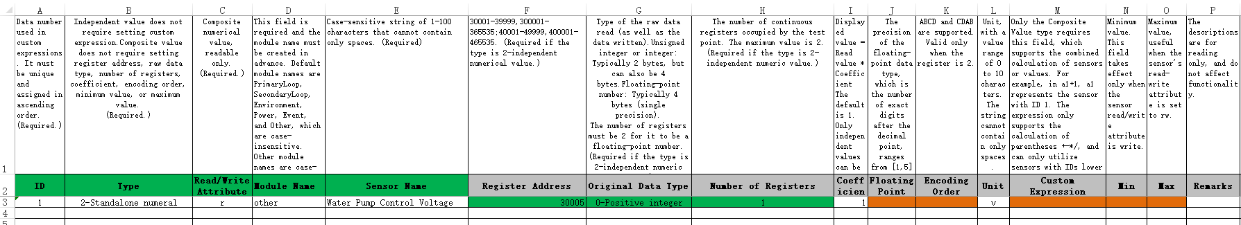
7. Select the numerical sensor worksheet, as shown in Figure 39. Configure the 16-bit independent numerical sensor named Pump Control Voltage.
¡ Enter ID 1.
¡ Select 2-Standalone numeral.
¡ Select r (read-only) as the read/writer property.
¡ Select other as the module name.
¡ Specify the sensor name. In this example, the sensor name is Water Pump Control Voltage.
¡ The register address is 30005.
¡ Select 0-Positive integer as the primitive data type. The sensor is a 16-bit sensor whose value is always an integer and does not support floating-point numbers.
¡ The number of registers is 1. Only one register is used.
¡ If you do not enter a coefficient, the default is 1.
¡ Floating point precision can only be entered when the primitive data type is set to floating point. Otherwise, do not specify the floating point precision.
¡ The encoding order needs to be specified only when the sensor contains two registers. Otherwise, do not specify the encoding order.
¡ The unit is in volts (V).
¡ Specify custom expressions only for composite status sensors.
¡ Specify the minimum and maximum values only when the sensor is rw (read-write).
Figure 73 Configuring a numerical sensor
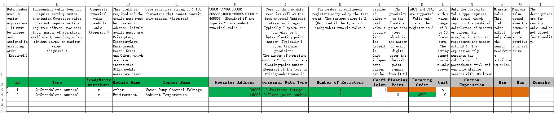
8. Select the numerical sensor worksheet, as shown in Figure 40. Configure a 32-bit floating-point independent numerical sensor named Ambient Temperature.
¡ Enter ID 2.
¡ Select 2-Standalone numeral.
¡ Select r (read-only) as the read/writer property.
¡ Select module name Environment.
¡ Specify the sensor name as Ambient Temperature.
¡ Specify the register address as 40005.
¡ Specify the number of registers as 2.
¡ If you do not enter a coefficient, UniSystem defaults to 1.
¡ Set the floating point prevision to 2. Enter an integer in the range of 1 to 5 only when the primitive data type is floating point.
¡ Select the coding order ABCD. This field is required only when the sensor includes two registers. Fill it out according to the storage mode of the sensor. ABCD uses big-endian format, meaning the highest byte comes first.
¡ The unit is °C (Celsius).
¡ Specify custom expressions only for composite status sensors.
¡ Specify the minimum and maximum values only when the sensor is rw (read-write).
Figure 74 Configuring a numerical sensor
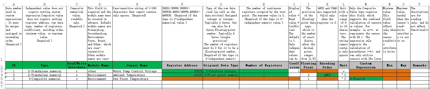
9. Select the numerical sensor worksheet, as shown in Figure 41. Configure a composite numerical sensor named Dew Point Temperature.
¡ Enter ID 3.
¡ Select 3-Compisite numeral.
¡ Select r (read-only) as the read/writer property.
¡ Select Environment as the module name.
¡ Enter Dew Point Temperature as the sensor name.
¡ Do not fill in the register address, primitive data type, number of registers, coefficient, coding order, minimum value, or maximum value.
¡ The unit is °C (Celsius).
¡ Enter the custom expression 0.5*a2+15, which sets the dew point temperature to half the ambient temperature value plus 15 degrees Celsius.
Figure 75 Configuring a numerical sensor
|
Parameter |
Description |
|
ID |
· Sensor ID used in custom expressions. This field is required. · An ID is a positive integer, unique, and arranged in ascending order. |
|
Type |
· Type of the sensor to be configured. This field is required. · Only 2-Independent numerical and 3-Composite numerical are supported. |
|
Read-write attribute |
· This field is required. Options include rw (read-write) and r (read-only). · The composite numerical sensor only supports selecting r (read-only). |
|
Module Name |
· The module name is required. · Module names used, other than the default ones, must be already added in the module name management section for the custom monitor template in the Infrastructure menu of the Web interface. · Default module names are PrimaryLoop, SecondaryLoop, Environment, Power, Event, and Other, which are case-insensitive. Other module names are case-sensitive. |
|
Sensor name |
· The sensor name is required and must be unique. · PowerOn, PowerOff, PowerStatus, SolenoidOff, and LeakageLiquid are reserved keywords and cannot be used here. · Description of the state value, a case-sensitive string of 1 to 200 characters that cannot contain only spaces. |
|
Register address |
· When the sensor type is a standalone numeric, you must fill in this field. Do not fill in this field when the sensor type is composite numeric. · The register address supports both 5-bit and 6-bit formats. ¡ The 5-bit address must be in the range of 30001-39999 or 40001-49999. ¡ The 6-bit address must be in the range of 300001-365536 or 400001-465536. · The read-write attribute for Zone 4 addresses can be set to r or rw, while the read-write attribute for Zone 3 addresses can only be r. · The register address of an independent numerical sensor is unique and cannot duplicate the address of any other sensor. |
|
Primitive data type |
· Represent the type of data read from the registers. Only 0-Positive integer, 1-Integer (negative value supported), and 2-Floating point are supported. · When the sensor type is a standalone numeric, you must fill in this field. Do not fill in this field when the sensor type is composite numeric. |
|
Number of registers |
· Represent the number of registers occupied by the sensor. Only 1 and 2 are supported. · When the sensor type is a standalone numeric, you must fill in this field. Do not fill in this field when the sensor type is composite numeric. · When the original data type is a positive integer or integer, the number of registers supported can be set to 1 or 2. · When the original data type is a floating-point number, the number of registers supported can only be set to 2. |
|
Coefficient |
· Represent the coefficient of the independent numerical sensor, which is displayed on the details interface as the product of the read value and the coefficient. · When the sensor type is a standalone numeric, this field is optional. Do not fill in this field when the sensor type is composite numeric. · The coefficient range is from 0 to 100 (excluding 0) and up to five decimal places are supported. |
|
Floating point precision |
· This field is optional. The value is an integer in the range of 1 to 5 and the default value is 2. · For standalone numerical sensors, when the original data type is not a floating-point number, do not fill in this field. |
|
Encoding sequence |
· For sensors with two registers, the coding sequence supports only ABCD and CDAB. ABCD means the high bit comes first, and CDAB means the low bit comes first. · This field must be filled in when the sensor type is standalone numerical with a register count of 2. In other cases, do not fill in this field. |
|
Unit |
· Unit for the sensor reading. This field is optional. · Unit, with a value range of 0 to 10 characters. The string cannot contain only spaces. |
|
Custom expression |
· Support combined calculation of sensors or values, such as a1+1, where a1 represents a value sensor with ID 1. · This field is required for composite numerical sensors. For independent numerical sensors, do not specify this field. · The expression supports only operations with parentheses, +, -, *, and /, and you can only use sensors with IDs before the sensor to be configured. · The expression string is limited to 120 characters and can contain a maximum of 32 sensor corresponding IDs and numbers. |
|
Min Value |
Minimum value that the sensor supports. This field is available only when the sensor's read-write properties are set to rw. |
|
Max Value |
Minimum value that the sensor supports. This field is available only when the sensor's read-write properties are set to rw. |
|
Remarks |
Only for remarks in Excel only. |
10. After configuring and saving the Excel template, upload the template on the page as shown in Figure 42. Once the template data is imported into the web page, supplement the basic information and click OK to complete the operation.
Figure 76 Importing and saving the Excel template