- Table of Contents
-
- H3C G3&G5 Servers HDM Configuration Examples-6W101
- 01-Redfish Configuration Examples
- 02-LDAP Configuration Examples
- 03-IPMI Configuration Examples
- 04-SNMP Configuration Examples
- 05-HDM Mobile Configuration Examples for Remote Access to a Server Through L2TP VPN
- 06-HDM Configuration Examples for Obtaining Event Logs Through the Redfish Interface
- 07-HDM SMTP Configuration Examples
- 08-HDM Zabbix-Based Server Monitoring Configuration Examples
- 09-HDM Network Settings Configuration Examples
- 10-hREST Configuration Examples for Configuring SNMP and Obtaining the CPU Information
- 11-HDM Configuration Management Configuration Examples
- 12-HDM AD Configuration Examples
- 13-HDM SOL Configuration Examples
- 14-HDM Unified Control Configuration Examples
- Related Documents
-
| Title | Size | Download |
|---|---|---|
| 13-HDM SOL Configuration Examples | 1.16 MB |
H3C G3&G5 Servers HDM
SOL Configuration Examples
Copyright © 2025 New H3C Technologies Co., Ltd. All rights reserved.
No part of this manual may be reproduced or transmitted in any form or by any means without prior written consent of New H3C Technologies Co., Ltd.
Except for the trademarks of New H3C Technologies Co., Ltd., any trademarks that may be mentioned in this document are the property of their respective owners.
The information in this document is subject to change without notice.
Introduction
HDM supports the Serial Over LAN (SOL) feature, which can change the objects connected to the serial ports on the server rear panel based on user requirements. This feature supports switching to the serial ports of the BIOS/OS, Mezz RAID, and smart network adapter. The following information provides examples for configuring the SOL feature of HDM.
Prerequisites
Procedures and information in the examples might be slightly different depending on the software or hardware version of the products.
The configuration was created and verified in a lab environment, and all the servers and software were started with the factory default configuration. If the device has been configured, ensure that the existing configuration does not conflict with the configuration in the following examples.
The following information is provided based on the assumption that you have basic knowledge of the SOL feature.
Applicable scenarios
The following information applies to the scenarios where SOL is implemented through HDM. The connected serial port can be switched at a click based on the actual application scenario.
Example: Configuring SOL
Network configuration
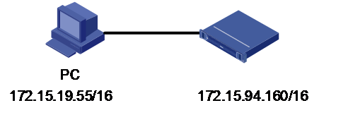
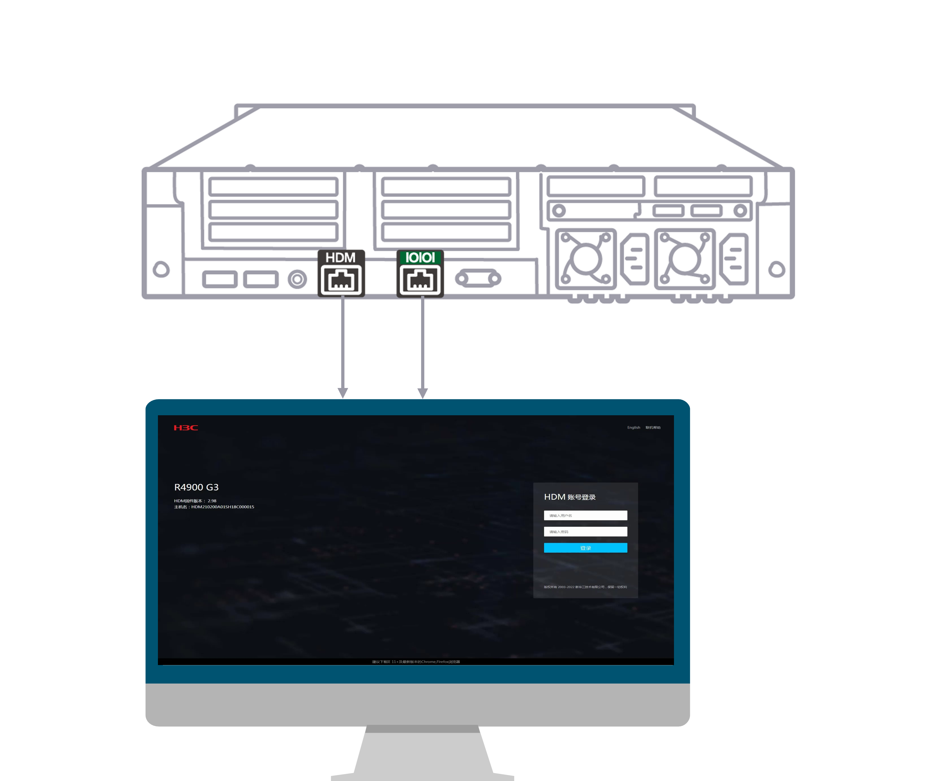
As shown in Figure 1, the H3C UniServer R4900 G3 server is connected with the PC client through the HDM dedicated port and serial port on the panel. Figure 2 shows the connections. In addition, network communication is normal. After the SQL connection mode is changed on the HDM Web page, it is required that the related SQL connection information can be output by the serial port on the panel.
· HDM software:
¡ IP address: 172.15.94.160/16
¡ Administrator account: admin
¡ Password: Password@_
· PC client:
¡ IP address: 172.15.19.55/16
Analysis
Log in to the HDM Web page, and configure the SOL connection mode. Use the IPMI command to activate the SOL connection mode. After successful activation, the related SOL information is output on the command line tool.
Software versions used
This example was created and verified on HDM 2.98.
Procedures
Logging in to HDM
1. Open a browser on a client, and then enter the HDM management IP address 172.15.94.160 to open the HDM login page. On the HDM login page, enter the default username admin and the default password Password@_, and click Login to log in to the HDM Web page, as shown in Figure 3.

2. Select Remote O&M > SOL Connection, as shown in Figure 4.
Figure 4 Configuring the SOL connection

(Optional) Disabling the SOL connection mode
|
|
NOTE: If the SOL connection mode is activated before you change the SOL connection mode, deactivate this mode first. |
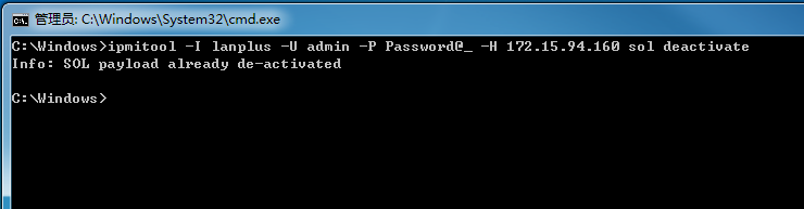
Open the command line window and execute the following IPMI command to deactivate the SOL connection mode, as shown in Figure 5.
ipmitool I lanplus –U admin –P Password@_ -H 172.15.94.160 sol deactivate
· -I connect_type: Specifies how to connect the managed device, connect_type is always set to lanplus, indicating that the IPMI v2.0 specification is used to establish a remote connection.
· -U username: Specifies the HDM username of the managed device.
· -P password: Specifies the password corresponding to the HDM username of the managed device.
· -H hostname: Specifies the IP address of the managed device.
· <command>: Specifies the action executed by the IPMI command. sol deactivate means to deactivate the SOL connection mode.
Figure 5 Disabling the SOL connection mode
Configure the SOL connection mode
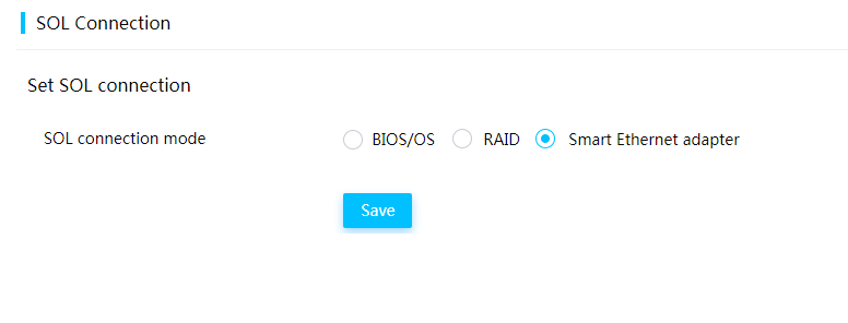
1. Select a SOL connection mode, for example, BIOS/OS, RAID, or Smart Ethernet adapter, as shown in Figure 6, Figure 7, and Figure 8.
Figure 6 Setting the SOL connection mode to BIOS/OS

Figure 7 Setting the SOL connection mode to RAID
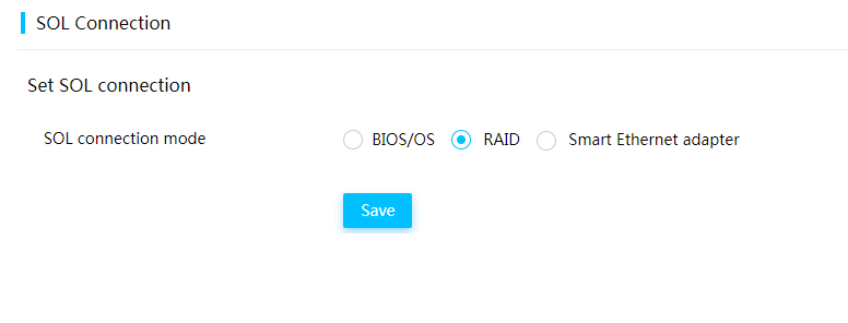
Figure 8 Setting the SOL connection mode to Smart Ethernet adapter
2. Click Save.
Activating the SOL connection mode
|
|
NOTE: After configuring the SOL connection mode, you need to execute the IPMI command to activate this mode. |
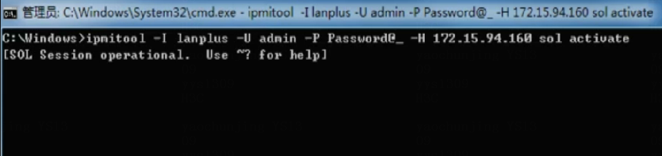
Open the command line window and execute the following IPMI command to activate the SOL connection mode, as shown in Figure 9.
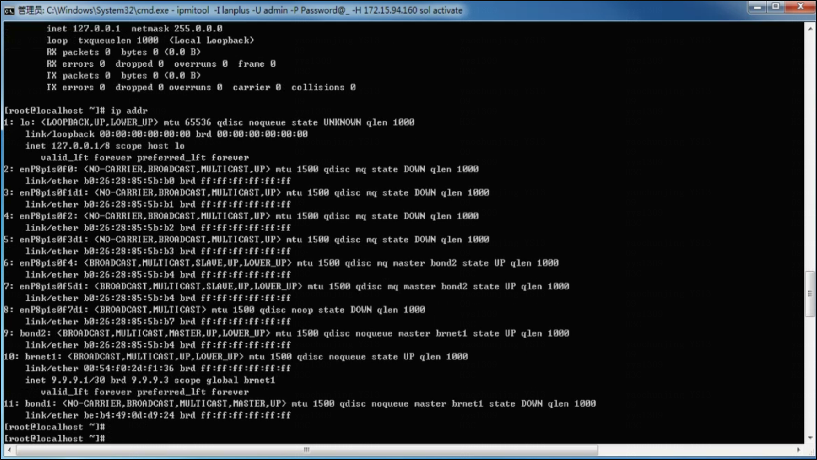
ipmitool I lanplus –U admin –P Password@_ -H 172.15.94.160 sol activate
· -I connect_type: Specifies how to connect the managed device, connect_type is always set to lanplus, indicating that the IPMI v2.0 specification is used to establish a remote connection.
· -U username: Specifies the HDM username of the managed device.
· -P password: Specifies the password corresponding to the HDM username of the managed device.
· -H hostname: Specifies the IP address of the managed device.
· <command>: Specifies the action executed by the IPMI command. sol activate means to activate the SOL connection mode.
Figure 9 Activating the SOL connection mode
Verifying the configuration
After the SOL connection mode is activated, the command line will output the related SOL connection information, as shown in Figure 10, Figure 11, and Figure 12.
Figure 10 Output in the BIOS/OS mode
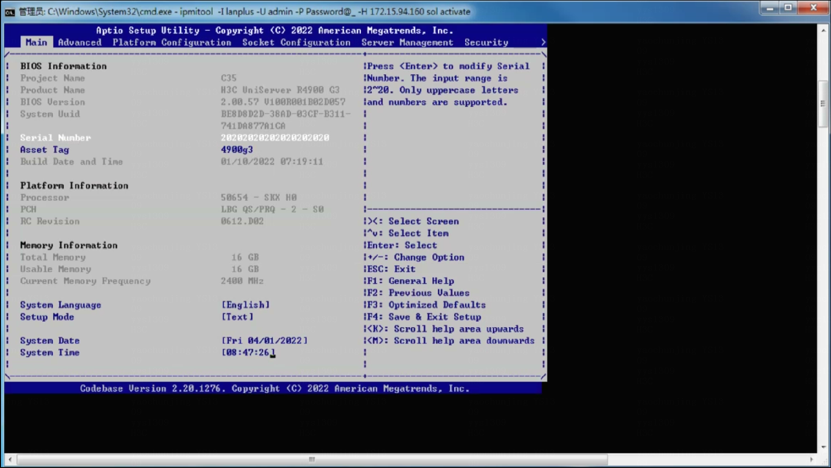
Figure 11 Output in the RAID mode
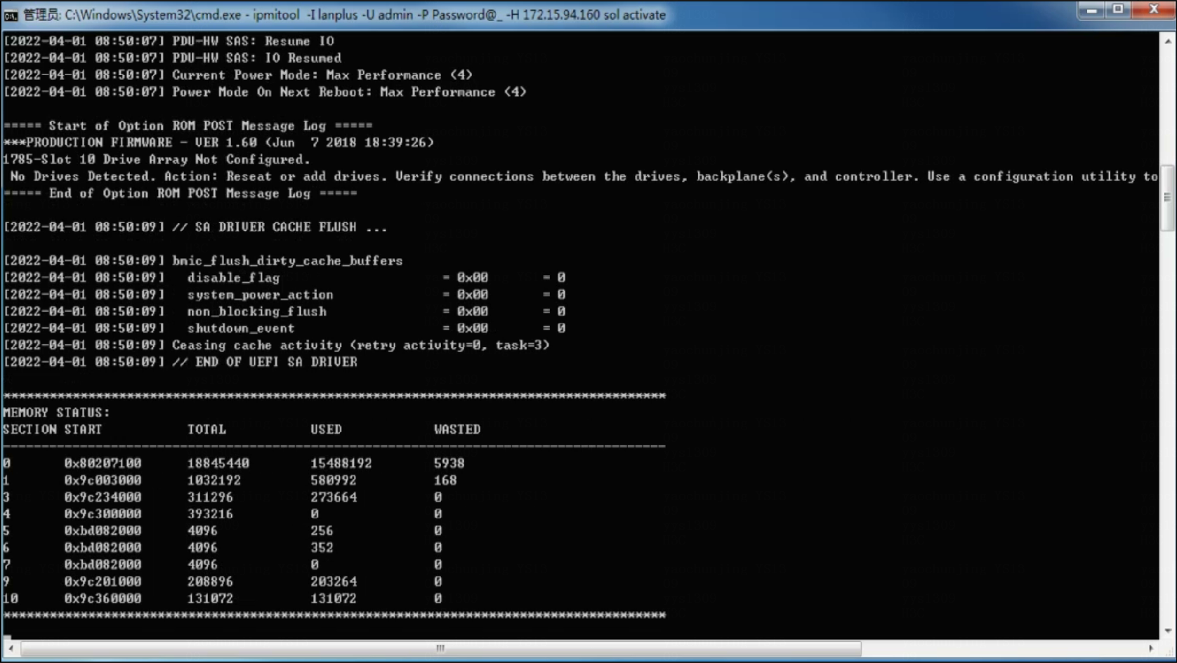
Figure 12 Output in the Smart Ethernet adapter mode
Related documentation
· H3C HDM Technology White Paper
· H3C Servers HDM User Guide
