- Table of Contents
- Related Documents
-
| Title | Size | Download |
|---|---|---|
| 01-BIER configuration | 635.39 KB |
Assigning the device to a sub-domain
Specifying a BFR ID for a BIER edge device
Configuring BIER encapsulation
Configuring the encapsulation type, BSL, and maximum SI
Configuring a multicast policy reserved address for a BFR in G-BIER
Configuring an End.BIER SID for a BFR in BIERv6
Configuring an End.RGB SID for a BFR in MSR6
Configuring a TTL processing mode on a BIER edge device
Configuring detecting the reachbility of the primary next hop through BFD session
Configuring static cross-AS BIER
Configuring BGP-based cross-AS BIER
Enabling the device to exchange routes with BIER path attributes with a peer or peer group
Enabling BGP BFR prefix proxying
Enabling BGP to redistribute the BIER information from an IGP
Display and maintenance commands for BIER
BIER overview
About BIER
Background
In traditional IP multicast and multicast VPN technologies, devices need to establish a multicast distribution tree for each multicast flow, with each node in the tree maintaining multicast flow state. For example, in public PIM multicast, it requires establishing a PIM multicast distribution tree for each multicast flow. In NG MVPN, it requires creating P2MP tunnels for each multicast flow, equivalent to creating a P2MP multicast tree. With the large-scale deployment of multicast services, the number of maintained multicast distribution trees increases sharply, resulting in a large number of multicast state entries on multicast nodes. When the network changes, this can cause slow convergence of multicast entries.
In addition, the coexistence of unicast routing protocols, multicast routing protocols, and MPLS protocols in the transport network increases the complexity of the control plane, leading to slow fault convergence and operational difficulties, making it challenging to evolve towards an SDN architecture network.
Definition
Bit Index Explicit Replication (BIER) is a new architecture for the forwarding of multicast data packets. BIER encapsulates the destination nodes of multicast packets in a bit string. It does not require a protocol for explicitly building multicast distribution trees, nor does it require intermediate nodes to maintain any per-flow state.
BIER benefits
BIER has the following benefits:
· Reduced control plane complexity—Intermediate nodes do not need to run specialized multicast control protocols such as PIM, and the control plane only needs to run unicast routing protocols such as IGP and BGP, simplifying the network's control plane.
· Enhanced multicast service scalability—BIER can establish a common forwarding table independent of specific multicast services, enabling both public and private multicast packets to be forwarded through this table. This eliminates the need for intermediate nodes to maintain multicast flow states or be aware of multicast services, thereby enhancing the scalability of multicast services.
· Improved multicast network stability—Because intermediate nodes do not need to be aware of multicast services, changes in multicast services do not affect these nodes. This enhances the stability of multicast networks, simplifying service deployment and network maintenance.
· Reduced coupling between services and networks—Using a layered architecture, BIER reduces the coupling with traditional link-state routing protocols. This not only facilitates a smooth transition of existing networks to BIER technology but also supports the evolution of service networks to SDN architecture.
BIER network structure
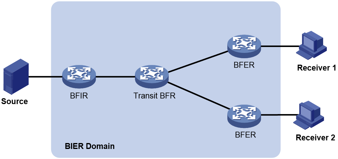
A router that supports BIER is known as a Bit-Forwarding Router (BFR). As shown in Figure 1, a BIER network consists of the following BFRs:
· Bit Forwarding Ingress Router (BFIR)—A multicast data packet enters a BIER domain at a BFIR. A BFIR encapsulates the multicast data packet as a BFIR packet.
· Transit BFR—A transit BFR receives a multicast data packet from one BFR to another BFR in the same BIER domain.
· Bit Forwarding Egress Router (BFER)—A multicast data packet leaves a BIER domain at a BFER. A BFER decapsulates the multicast data packet and sends it to multicast receivers.
Figure 1 BIER network structure
Basic concepts
BIER domain and BIER sub-domain
All BFRs in a network are referred to as a BIER domain. A BIER domain can contain one or more sub-domains. Each sub-domain is identified by a sub-domain ID. All BFIRs and BFERs in a sub-domain are called BIER edge devices.
BFR ID
A BFR ID uniquely identifies a BIER edge device in a sub-domain. A transit BFR does not need to have a BFR ID.
BFR prefix
A BFR prefix is an IP address that uniquely identifies a BFR in a sub-domain. A BFR prefix must be routable in the sub-domain.
Bit string
A bit string represents a set of BIER edge devices, with each bit corresponding to a BFR ID, starting from the rightmost position. The bit string length (BSL) refers to the number of bits in the bit string. A bit string with three bits can identify a maximum of three BIER edge devices. The BIER edge device with BFR ID 1 is represented as 001.
Set identifier and Max-SI
When the number of BFR IDs is greater than the number of bits in the bit string, the bit string needs to be divided into sets identified by set identifiers (SI). The start SI value is 0.
The Max-Set Identifier (Max-SI) can used to set the number of Sis. The Max-SI is (Maximum BFR ID–1)/BSL rounded down to the nearest integer. If the BFR IDs start with 1 and are contiguous, the maximum BFR ID is the number of edge devices.
For example, if a BIER sub-domain has 10 edge devices and BFR IDs start with 1 and are contiguous, the maximum BFR ID is 10. If the bit string length is 4, the bit string needs to be divided into three SIs (SI 0, SI 1, and SI 2). The Max-SI is 2: (Maximum BFR ID–1)/BSL rounded down to the nearest integer.
Bit Index Routing Table
The Bit Index Routing Table (BIRT) is generated based on the BIER information ((sub-domain, BSL, and BFR ID) and routing information carried by IGP. The BIRT is used to guide the forwarding of BIER packets in a BIER sub-domain.
Forwarding Bit Mask
The Forwarding Bit Mask (F-BM) represents a set of edge nodes in a BIER sub-domain that are reachable through a BFR neighbor (BFR-NBR). The bit mask is obtained by taking the logical OR of the bit strings of all reachable edge nodes.
Bit Index Forwarding Table
The Bit Index Forwarding Table (BIFT) can guide the per-hop forwarding of multicast traffic in a BIER sub-domain.
The BIFT is used to map from the BFR ID of a BFER to the corresponding F-BM and BFR-NBR. Multiple BIFT can exist on a BFR. Each BIFT is identified by a combination of the BSL, SD, and SI).
Layering
As specified in RFC 8279, the BIER architecture consists of three layers: routing underlay, BIER layer, and multicast flow overlay, as shown in Figure 2.
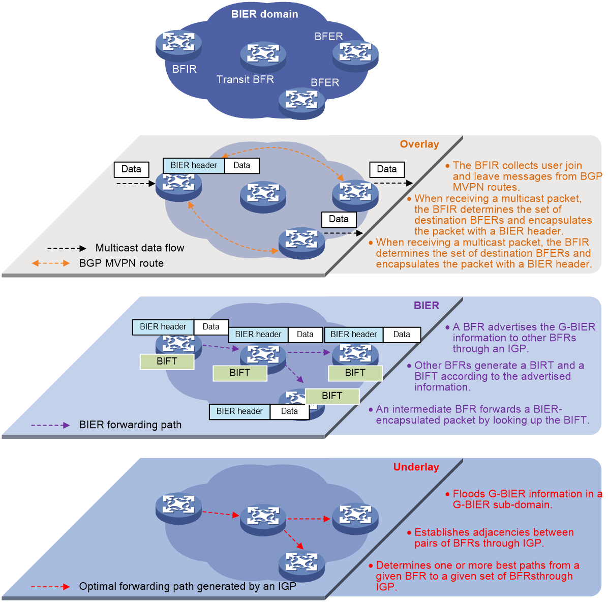
Routing underlay
The routing underlay uses an IGP (only IS-IS is supported) to flood BIER information through extended TLVs in a BIER sub-domain. A BFR generates routes to all BFR prefixes (BFR IDs) based on the IGP. Therefore, the routing underlay establishes adjacencies between pairs of BFRs and determines one or more best paths from a given BFR to a given set of BFRs.
BIER layer
The BIER layer consists of the protocols and procedures that are used in order to transmit a multicast data packet across a BIER domain.
1. A BFR advertises the BIER information to other BFRs in the BIER domain through IGP.
2. Other BFRs generate a BIRT and a BIFT according to the advertised information.
3. An intermediate BFR forwards a BIER-encapsulated packet by looking up the BIFT table.
Multicast flow overlay
The multicast flow overlay is responsible for control plane processing. It collects join and leave messages of multicast groups between BFIRs and BFERs. When a BFIR receives a multicast data packet from outside the BIER domain, the BFIR determines the set of BFERs for that packet. When a BFER receives a BIER-encapsulated packet from inside the BIER domain, the BFER decapsulates the packet and forwards it.
BIER control plane
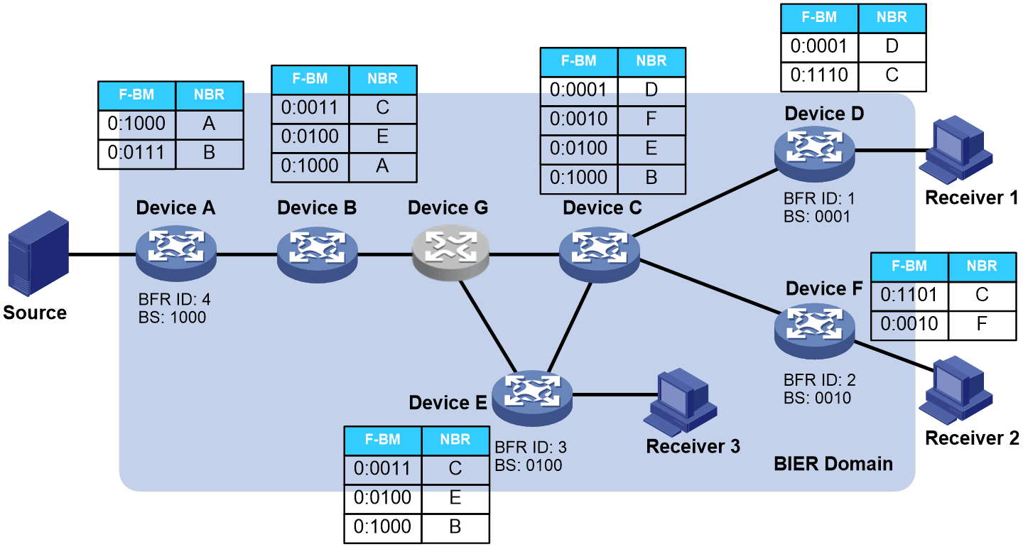
The BIER information (including SD, BFR prefix, BFR ID) configured on BFRs is flooded within the BIER domain through the IGP protocol. The IGP calculates a BIER shortest path tree, with the BFIR as the root, and transit BFRs and BFERs as leaves, based on the flooded BIER information from neighboring nodes. BFRs generate BIRTs based on the BIER shortest path tree and further generate BIFTs to guide BIER forwarding.
As shown in Figure 3, when a node (Device G) in the BIER domain does not support BIER, it joins all its child nodes to the BIER shortest path tree as leaf nodes. If a child node does not support BIER, it continues to iterate down to child nodes that do support BIER. For example, if Device G does not support BIER, it will pass the BIER information of its child nodes, Device C and Device E, to Device B, which then generates BIFT table entries indicating non-directly-connected neighbors (Device C and Device E).
IGP extension
The BIER information (including SD, BFR prefix, BFR ID) configured on BFRs is flooded within the BIER domain through an IGP, such as OSPF and IS-IS. The IGP calculates a BIER shortest path tree, with the BFIR as the root, and transit BFRs and BFERs as leaves, based on the flooded BIER information from neighboring nodes. BFRs generate BIRTs based on the BIER shortest path tree and further generate BIFTs to guide BIER forwarding.
RFC 8401 and RFC 8444 defined IS-IS extension and OSPF extension for the BIER control plane, respectively. RFC 9272 released in 2022 updated RFC 8401 and RFC 8444. This section takes IS-IS extension as an example.
General IS-IS extension for BIER
The BIER information is advertised in a subdomain through general IS-IS extension for BIER. Nodes receiving BIER information will generate the appropriate BIFT if they support BIER forwarding. If they do not support BIER forwarding, IS-IS floods the received BIER information without processing it.
Table 1 shows the BIER information distribution mechanism defined in RFC 8401. Specially, the BIER Info Sub-TLV is added to distribute BIER information.
Table 1 BIER information distribution mechanism
|
Type |
Description |
|
TLV |
TLVs are used to advertise BFR prefixes of nodes. All BIER information is carried in the following TLVs: · TLV 135 (Extended IP Reachability TLV) defined in RFC 5305. · TLV 236 (IPv6 Reachability TLV) defined in RFC 5308. · TLV 235 (Multi-Topology Reachable IPv4 Prefixes TLV) and TLV 237 (Multi-Topology Reachable IPv6 Prefixes TLV) defined in RFC 5308. |
|
Sub-TLV |
BIER Info Sub-TLV, defined in RFC 8401 and used to advertise the subdomain and BFR ID. |
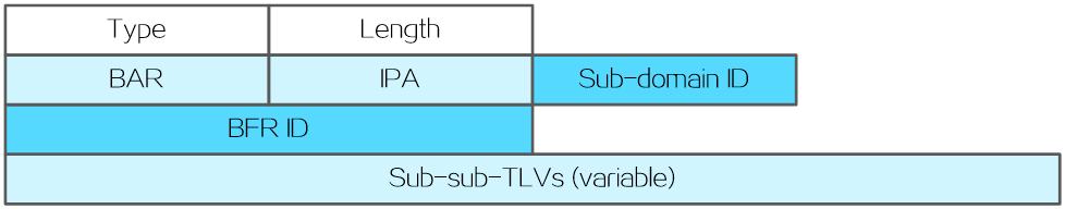
Figure 4 shows the format of the BIER Info Sub-TLV. Table 2 shows the meaning of each field.
|
Field |
Length |
Description |
|
Type |
8 bits |
Type of the sub-TLV. The value is 32, which indicates BIER Info Sub-TLV. |
|
Length |
8 bits |
Length of the sub-TLV. |
|
BAR |
8 bits |
BIER algorithm. |
|
IPA |
8 bits |
IGP algorithm. |
|
Sub-domain ID |
8 bits |
BIER subdomain ID. |
|
BFR ID |
16 bits |
BFR ID, which uniquely identifies a BIER edge device in a BIER subdomain. |
|
Sub-sub-TLVs |
Variable length |
Optional sub-sub-TLVs. |
IS-IS extension for G-BIER, BIERv6, and MSR6
The following sub-sub-TLVs are added for G-BIER, BIERv6, and MSR6:
· BIER capability sub-sub-TLV—Advertises BIER capabilities and max-SI and BSL information of nodes. The three encapsulation types use similar capability sub-sub-TLVs.
· Address sub-sub-TLV—Advertises address information. The neighbor nodes use the advertised IPv6 address as the destination address of packets sent to the node. This type of sub-sub-TLV has different meanings for different encapsulation types.
¡ For G-BIER, this sub-sub-TLV advertises the MPRA. Therefore, the address sub-sub-TLV is also called MPRA sub-sub-TLV.
¡ For BIERv6, this sub-sub-TLV advertises End.BIER SID. Therefore, the address sub-sub-TLV is also called End.BIER sub-sub-TLV.
¡ For MSR6, this sub-sub-TLV advertises End.RGB SID. Therefore, the address sub-sub-TLV is also called End.RGB sub-sub-TLV.
BIER capability sub-sub-TLV
The BIER capability sub-sub-TLV is carried in BIER Info Sub-TLV. It uses the fields in Table 3 to advertise max-SI and BSL information.
|
Field |
Description |
|
Type |
· Type of the sub-sub-TLV. |
|
Length |
Length of the sub-sub-TLV. |
|
Max-SI |
Maximum SI. The start value of the SI is 0. The maximum SI is (Maximum BFR ID–1)/BSL rounded down to the nearest integer. For example, if the maximum BFR ID is 10 in a BIER sub-domain and the bit string length is 4, the bit string needs to be divided into three SIs (SI 0, SI 1, and SI 2). |
|
BSL |
Bit string length. |
Address sub-sub-TLV
The address sub-sub-TLV is carried in BIER Info Sub-TLV. The neighbor nodes use the advertised IPv6 address as the destination address of packets sent to the node. This sub-sub-TLV uses the fields in Table 4 to advertise the MPRA, End.BIER, or End.RGB.
|
Field |
Length |
Description |
|
Type |
8 bits |
Type of the sub-sub-TLV. |
|
Length |
8 bits |
Length of the sub-sub-TLV. |
|
MPRA |
128 bits |
16-byte MPRA. |
|
End.BIER SID |
128 bits |
16-byte End.BIER SID. |
|
End.RGB SID |
128 bits |
16-byte End.RGB SID . |
BGP extension
In a cross-domain scenario, a BFIR uses BGP to advertise and collect BIER information to establish mappings between BIER tunnels and BIER information and to guide BIER forwarding. The draft-ietf-bier-idr-extensions defines a BGP path attribute (BIER path attribute) to advertise BIER information through BGP.
The BGP extension uses a similar information distribution mechanism as the IS-IS extension.
· Sub-TLV—Advertises the BIER sub-domain ID and the BFR ID that advertises the route.
· The following sub-sub-TLVs are used:
¡ BIER capability sub-sub-TLV—Advertises BIER capabilities and max-SI and BSL information of nodes. The three encapsulation types use similar capability sub-sub-TLVs.
¡ Address sub-sub-TLV—Advertises address information. The neighbor nodes use the advertised IPv6 address as the destination address of packets sent to the node. This type of sub-sub-TLV has different meanings for different encapsulation types.
¡ BFR ID range sub-sub-TLV—Advertises the BFR ID range in an AS and contains the fields in Table 5.
|
Field |
Description |
|
Type |
Type of the sub-sub-TLV. |
|
Length |
Length of the sub-sub-TLV. |
|
BFR ID start |
Start BFR ID. |
|
BFR ID end/BFR ID range |
End BFR ID or number of contiguous BFR IDs (starting from the start BFR ID). |
BIER encapsulation types
Overview
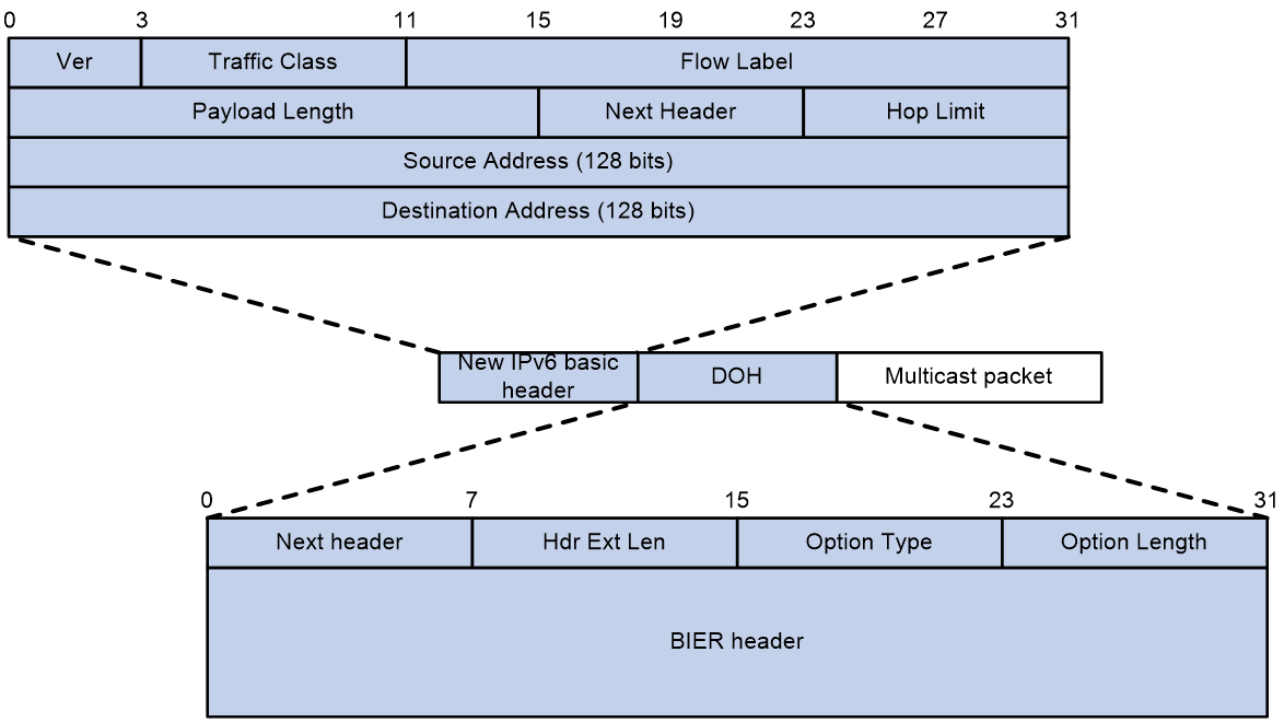
BIER encapsulates a multicast data packet as a BIER packet by adding a new IPv6 header, as shown in Figure 5. The Next Header field in the new IPv6 header is 60, which indicates that the next header is Destination Options Header (DOH). The DOH contains four fields and the BIER header. Table 6 shows the meanings of the four fields.
|
Field |
Length |
Description |
|
Next Header |
8 bits |
Type of the next header. |
|
Hdr Ext Len |
8 bits |
Length of the IPv6 extension header. |
|
Option Type |
8 bits |
Option type of the DOH (encapsulation type of the BIER header): · Generalized BIER (G-BIER) · Bit Index Explicit Replication IPv6 Encapsulation (BIERv6) · Multicast Source Routing over IPv6 (MSR6) This field is 0x7A for all the three encapsulation types. |
|
Option Length |
8 bits |
Option length in bytes, the length of the BIER header. |
Table 7 describes BIER header encapsulation types supported by H3C. Different encapsulation types have different packet formats.
|
Encapsulation type |
Description |
|
G-BIER |
Proposed by China Mobile, G-BIER revised the BIER header to adapt to IPv6. |
|
BIERv6 |
As a new multicast scheme based on native IPv6, BIERv6 combines the advantages of both IPv6 and BIER, can integrate into an SRv6 network seamlessly, and simplifies protocol complexity. |
|
MSR6 |
MSR6 is a multicast solution that uses the IPv6 data plane to integrate unicast and multicast services within the MSR6 BE domain. |
G-BIER
G-BIER is proposed by China Mobile. G-BIER revised the BIER header to adapt to IPv6.
IPv6 basic header
G-BIER uses the following conventions related to the following fields in the IPv6 basic header:
· Source Address—The source address is the multicast service source address and remains unchanged when a multicast packet is transmitted over a public network. For more information about multicast service source address, see multicast VPN configuration in IP Multicast Configuration Guide.
· Destination Address—The destination address is the multicast policy reserved address for BIER forwarding. This address must be routable in a sub-domain.
G-BIER header
As shown in Figure 6, the G-BIER header is included in the DOH, and the Option Type is G-BIER.
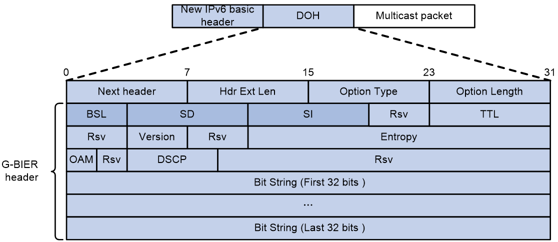
Table 8 describes the fields in the G-BIER header.
|
Field |
Length |
Description |
|
BSL |
4 bits |
Identifies the length in bits of the BitString. The value range is 1 to 7. · 1—The bit string length is 64. · 2—The bit string length is 128. · 3—The bit string length is 256. · 4—The bit string length is 512. · 5—The bit string length is 1024. · 6—The bit string length is 2048. · 7—The bit string length is 4096. |
|
SD |
8 bits |
Indicates the ID of the BIER sub-domain. |
|
SI |
8 bits |
Indicates the set identifier. |
|
Rsv |
4 bits |
Reserved field. It should be set to all 0s for outgoing packets and ignored for incoming packets. |
|
TTL |
8 bits |
Time to Live field to prevent loops. |
|
Version |
4 bits |
Identifies the version of the BIER header, which is fixed at 0. |
|
Entropy |
20 bits |
Indicates the entropy value used for load-balancing purposes when there are ECMP paths. The load-balancing procedure will choose the same path for any two packets that have the same entropy value and the same BitString. |
|
OAM |
2 bits |
Used for OAM purposes. The default value of this field is 0. |
|
DSCP |
6 bits |
Indicates the forwarding priority of the packet. |
|
Bit String |
Depends on the BSL value |
Bit string. |
BIERv6
As a new multicast scheme based on native IPv6, BIERv6 combines the advantages of both IPv6 and BIER, can integrate into an SRv6 network seamlessly, and simplifies protocol complexity.
To use BIERv6 encapsulation, make sure all BFRs in a sub-domain support SRv6. For more information about SRv6, see Segment Routing Configuration Guide.
IPv6 basic header
BIERv6 uses the following conventions related to the following fields in the IPv6 basic header:
· Source Address—The source address is the source address of the BIERv6 tunnel and remains unchanged when a multicast packet is transmitted over a public network.
· Destination Address—The destination address is an End.BIER SID used for BIER forwarding. This address must be routable in a sub-domain. If the destination address of an IPv6 packet is an End.BIER SID, an BFR will perform BIERv6 forwarding for the packet.
BIERv6 header
As shown in Figure 7, the DOH contains the BIERv6 header, and the Option Type is BIERv6. The BIERv6 header complies with the non-MPLS encapsulation specifications in RFC 8296. The fields in deep color are different fields from the G-BIER header.
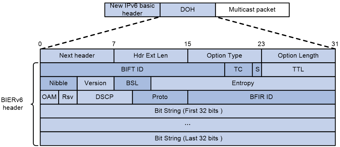
Table 9 describes the fields in the BIERv6 header.
|
Field |
Length |
Description |
|
BIFT ID |
20 bits |
Uniquely identifies a BIFT. |
|
TC |
3 bits |
Traffic class field used for QoS. |
|
S |
1 bit |
Reserved field. It should be set to 1 for outgoing packets and ignored for incoming packets. |
|
TTL |
8 bits |
Time to Live field to indicate the number of hops a BIERv6 packet can traverse. The TTL is decreased by 1 when a packet traverses a BIERv6 node. When a node receives a packet with TTL 0, it will discard the packet. |
|
Nibble |
4 bits |
Reserved field. It should be set to 0000 for outgoing packets and ignored for incoming packets. |
|
Version |
4 bits |
Identifies the version of the BIER header, which is fixed at 0. |
|
BSL |
4 bits |
Identifies the length in bits of the BitString. The value range is 1 to 7. · 1—The bit string length is 64. · 2—The bit string length is 128. · 3—The bit string length is 256. · 4—The bit string length is 512. · 5—The bit string length is 1024. · 6—The bit string length is 2048. · 7—The bit string length is 4096. |
|
Entropy |
20 bits |
Indicates the entropy value used for load-balancing purposes when there are ECMP paths. The load-balancing procedure will choose the same path for any two packets that have the same entropy value and the same BitString. |
|
OAM |
2 bits |
Used for OAM purposes. The default value of this field is 0. |
|
Rsv |
2 bits |
Reserved field. It should be set to all 0s for outgoing packets and ignored for incoming packets. |
|
DSCP |
6 bits |
Indicates the forwarding priority of the packet. |
|
Proto |
6 bits |
Indicates the payload type (lower-level protocol) after the BIERv6 header. |
|
BFIR ID |
16 bits |
BFIR ID. |
|
Bit String |
Depends on the BSL value |
Bit string. |
MSR6
MSR6 uses the IPv6 data plane to integrate unicast and multicast services within the MSR6 BE domain. Leveraging the IPv6 unicast reachability feature, MSR6 BE can penetrate non-BIER nodes. In early MSR6 BE deployments, routers that do not support MSR6 BE forwarding but support IPv6 forwarding will route traffic based on the IPv6 destination address.
IPv6 basic header
MSR6 uses the following conventions related to the following fields in the IPv6 basic header:
· Source Address—The source address is the source address of the MSR6 tunnel and remains unchanged when a multicast packet is transmitted over a public network.
· Destination Address—The destination address is an End.RGB SID used for BIER forwarding. This address must be routable in a sub-domain. If the destination address of an IPv6 packet is an End.RGB SID, an BFR will perform MSR6 forwarding for the packet.
MSR6 header
As shown in Figure 8, the DOH contains the MSR6 header, and the Option Type is MSR6. The BIERv6 header is similar to the non-MPLS BIER header in RFC 8296, but some fields such as Nibble and Proto are replaced with reserved fields (Rsv). A reserved field should be set to 0 for outgoing packets and ignored for incoming packets. The fields in deep color are different fields from the BIERv6 header.
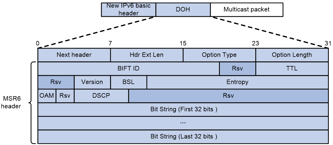
Table 10 describes the fields in the MSR6 header.
|
Field |
Length |
Description |
|
BIFT ID |
20 bits |
Uniquely identifies a BIFT. |
|
TTL |
8 bits |
Time to Live field to indicate the number of hops an MSR6 packet can traverse. The TTL is decreased by 1 when a packet traverses an MSR6 node. When a node receives a packet with TTL 0, it will discard the packet. |
|
Version |
4 bits |
Identifies the version of the BIER header, which is fixed at 0. |
|
BSL |
4 bits |
Identifies the length in bits of the BitString. The value range is 1 to 7. · 1—The bit string length is 64. · 2—The bit string length is 128. · 3—The bit string length is 256. · 4—The bit string length is 512. · 5—The bit string length is 1024. · 6—The bit string length is 2048. · 7—The bit string length is 4096. |
|
Entropy |
20 bits |
Indicates the entropy value used for load-balancing purposes when there are ECMP paths. The load-balancing procedure will choose the same path for any two packets that have the same entropy value and the same BitString. |
|
OAM |
2 bits |
Used for OAM purposes. The default value of this field is 0. |
|
DSCP |
6 bits |
Indicates the forwarding priority of the packet. |
|
Bit String |
Depends on the BSL value |
Bit string. |
BIER forwarding plane
To facilitate description and understanding, this section introduces the BIER forwarding plane using an example where Max-SI is 0 and BSL is 4 bits.
According to the definition in RFC 8279, if a device needs to forward multicast data encapsulated with BIER, the device should execute the following actions:
1. Identify the corresponding BIER sub-domain, BSL, BS, and SI to determine which BFERs need to receive the multicast data.
2. The routing underlay determines the next hop to each BFER.
3. Assign BFERs with the same next hop to one group.
4. For each BFER group, replicate multicast data and forward it to the next hop. If the next hop is empty (such as when the route is unreachable), discard the multicast data.
BIRT and BIFT
To ensure smooth forwarding actions, RFC 8279 defines the BIRT and BIFT.
A Bit Index Routing Table (BIRT) records mappings between the BFR IDs, destination node BFR prefixes, and the next-hop BFR neighbors (BFR-NBR). As shown in Figure 9, BFR E can look up the BIFT based on the BFR ID, SI, and BS information in BIER multicast data, to obtain the corresponding destination node BFR prefixes and next-hop BFR neighbors.
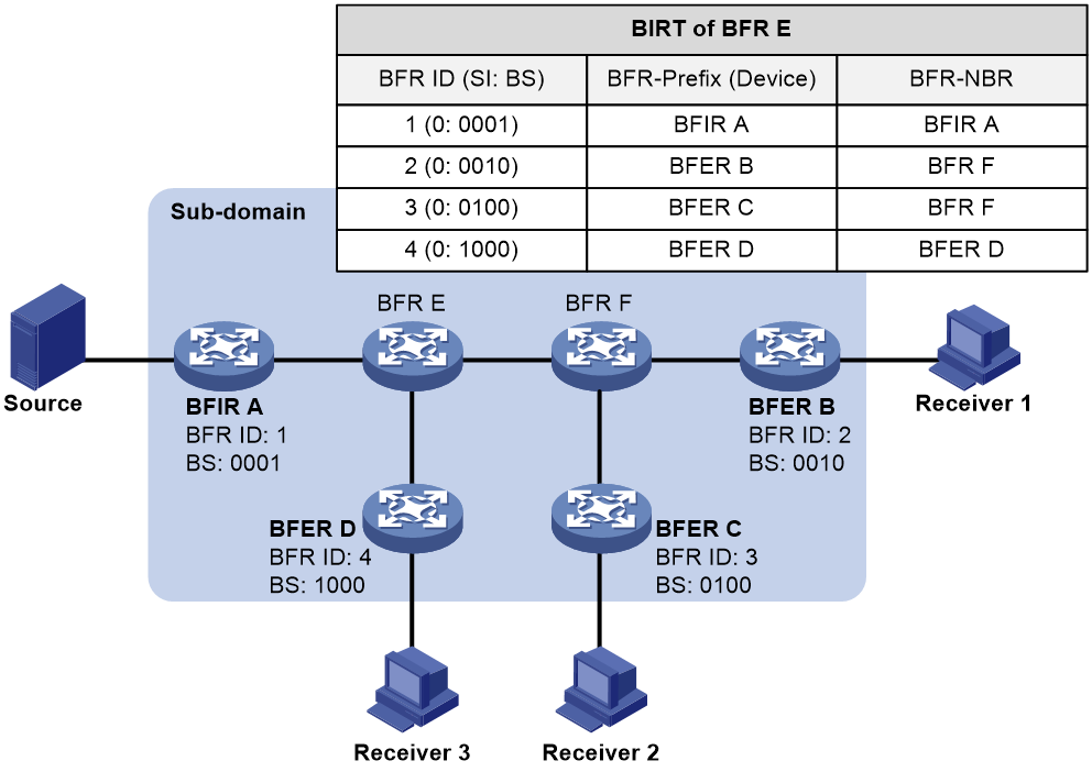
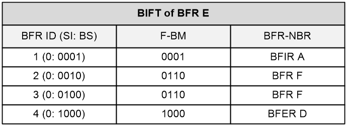
To facilitate forwarding statistics collection, BIER groups rows in the BIRT with identical SI and BFR-NBR values. Therefore, the corresponding BS rows can be combined by using a bitwise logical OR operation to obtain the F-BM, which guides the next forwarding action. The BIFT records the BFR ID information and the mappings between F-BM and BFR-NBR. It is a derivative of the BIRT.
For example, on BFR E, as shown in Figure 9, the SI and BFR-NBR in the second and third rows are identical, so group them by calculating the F-BM. This allows the creation of a BIFT on BFR E, as shown in Figure 10.
Forwarding process
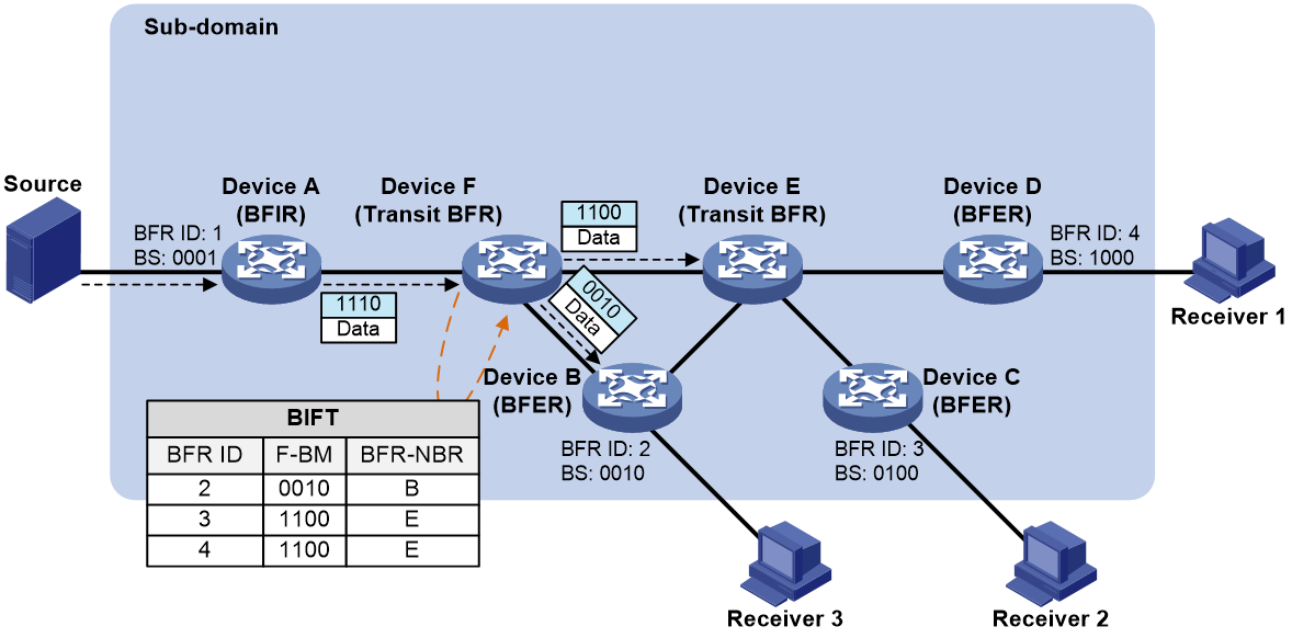
As shown in Figure 11, Device A acts as the BFIR, Devices B, C, and D act as BFERs, and Devices E and F act as transit BFRs. For devices A, B, C, and D, the BFR IDs are 1, 2, 3, and 4, respectively.
Figure 11 BIER traffic forwarding
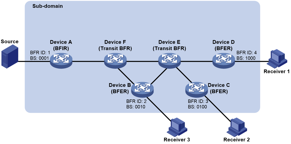
Each BFER has downstream receivers, and the three receivers belong to the same multicast group. On each device within a BIER sub-domain, a BIFT is established based on the information flooded by the IGP protocol. Additionally, the BFIR builds mappings between BIER tunnels and BIER information (BSL, SD, SI, and BS) based on the following information:
· BIER tunnel configuration: The BSL and SD that are configured when a selective or inclusive tunnel is created.
· Information learned through BGP MVPN routes:
¡ The SI calculated based on the BFR ID carried by the type-4 routes and the value of the BSL configured in the corresponding BIER sub-domain.
¡ The BS generated based on the user join and leave messages collected by using BGP MVPN routes. The receiver identified by the BS also corresponds to the destination node of the BIER tunnel.
BFIR forwarding process
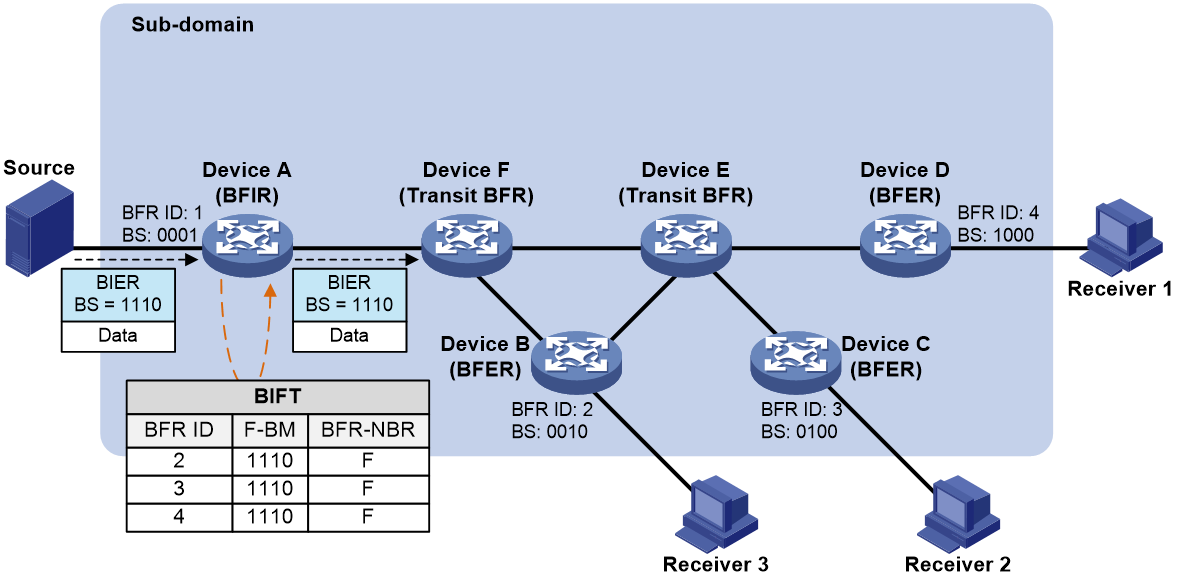
As shown in Figure 12, when Device A, acting as a BFIR, receives an IP multicast packet sent by a multicast source to the multicast group, it will execute the following actions:
1. Based on the information in the IPv6 basic header, search for the multicast forwarding entry, validate the corresponding outgoing interface and BIER tunnel, and obtain the BIFT ID (uniquely determined by the BSL, SD, and SI) and BS through the mappings between the BIER tunnels and BIER information. In this example, the BS is 1110, denoted as BS(a0).
2. Search for the corresponding BIFT based on the BIFT ID and find that the next hop neighbor to all three BFERs is Device F.
3. Perform a bitwise AND operation between BS(a0) and each row of F-BM in the table. In the row-by-row calculation, any bit that evaluates to 1 after a bitwise AND operation will not participate in subsequent bitwise AND calculations. Use x to represent bits that do not participate in the calculation. The detailed steps for row-by-row calculation are as follows:
¡ First row (BFR ID=2): Perform a bitwise AND operation on the F-BM in this row with BS(a0). The result is 1110, which is recorded as BS(a1).
¡ Second row (BFR ID=3): The result is xxx0. After the bits that do not require calculation are set to 0, the result is 0000. An all-zero result is ignored.
¡ Third row (BFR ID=4): The result is xxx0. After the bits that do not require calculation are set to 0, the result is 0000. An all-zero result is ignored.
4. Encapsulate the multicast packet by using BS(a1) in the BIER packet format, and forward it to the next hop neighbor, Device F.
Figure 12 BFIR forwarding process
Transit BFR forwarding process
As shown in Figure 13, when Device F, acting as a Transit BFR, receives an IP multicast packet forwarded by Device A, it will execute the following actions:
1. Check the information encapsulated in the BIER header to obtain the BIFT ID and BS. In this example, the BS is 1110, denoted as BS(b0). The BIERv6 and MSR6 headers directly contain the BIFT ID. However, the G-BIER header does not directly contain the BIFT ID, which must be uniquely determined based on the BS, BSL, and SI.
2. Use the BIFT ID to find the corresponding BIFT and determine that the next hop neighbor to Device C and Device D is Device E, while the next hop neighbor to Device B is Device B itself.
3. Perform a bitwise AND operation between BS(b0) and each row of F-BM in the table. In the row-by-row calculation, any bit that evaluates to 1 after a bitwise AND operation will not participate in subsequent bitwise AND calculations. Use x to represent bits that do not participate in the calculation. The detailed steps for row-by-row calculation are as follows:
¡ First row (BFR ID=2): Perform a bitwise AND operation on the F-BM in this row with BS(b0). The result is 0010, which is recorded as BS(b1).
¡ Second row (BFR ID=3): The result is 11x0. After the bits that do not require calculation are set to 0, the result is 1100, which is denoted as BS(b2).
¡ Third row (BFR ID=4): The result is xxx0. After the bits that do not require calculation are set to 0, the result is 0000. An all-zero result is ignored.
4. Copy the multicast packet into two copies and encapsulate each one in the BIER packet format with BS(b1) and BS(b2) separately.
5. Transmit two multicast packets to the next hop neighbors Device B and Device E separately.
Figure 13 Transit BFR forwarding process
When Device E, also a Transit BFR, receives an IP multicast packet forwarded by Device F, it performs similar operations, which are not reiterated here.
BFER forwarding process
When Device B, acting as a BFER, receives an IP multicast packet forwarded by Device F, it will execute the following actions:
1. By examining the encapsulated information in the BIER header, obtain the BIFT ID and BS (0010 in this example).
2. Use the BIFT ID to locate the corresponding BIFT. If only the F-BM of this node, after performing a bitwise AND logical operation with BS in the packet, has a result of a non-zero value, this node is a Bit-Forwarding Egress Router (BFER) and must terminate BIER forwarding.
3. After decapsulating the multicast packet from the BIER header, Device B forwards it to downstream receivers according to the multicast forwarding table.
The operations on Device E and Device F are similar to those on Device D, and will not be repeated.
Cross-AS BIER
Cross-AS BIER indicates that a BIER network spans multiple ASs and multicast traffic passes through multiple ASs during BIER forwarding. An IGP can flood BIER information within an AS and cannot generate cross-AS BIER forwarding entries. Cross-AS BIER requires that a BIER node can obtain the BIER information (such as BFR ID) of BIER nodes in another AS. The device supports implementing cross-AS BIER through static configuration and BGP advertisement.
Static cross-AS BIER
You implement cross-AS BIER by manually specifying the BFR neighbor in another domain and the BFR ID range of BIER edge devices that can be reached through the BFR neighbor.
BGP-based cross-AS BIER
BGP can transfer BIER information between ASs. The BIER information can guide the forwarding of BIER packets. BGP encapsulates the following BIER information in UPDATE messages:
· BFR prefix—Encapsulated in the NLRI field.
· BIER Path Attribute—A new attribute that contains information such as BIER sub-domain, BFR ID, BSL, and destination address.
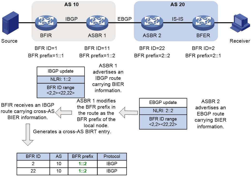
As shown in Figure 14, the BIER network spans AS 10 and AS 20. IS-IS is used to transfer BIER information in AS 20, and IBGP is used to transfer BIER information in AS 10. On ASBR 2, BIER information collected by IS-IS in AS 20 can be imported to BGP and then sent to ASBR 1 through an EBGP session. ASBR 1 forwards an EBGP route to the BFIR. The BFIR generates a cross-AS BIRT entry based on the BIER information carried in the received IBGP route. The BFR prefix of the BFR ID of the BFER is the BFR prefix of ASBR 2 (2::2). The BFIR uses ASBR 2 as the next hop when forwarding multicast packets.
|
|
NOTE: Carried in a BGP route, the BFR ID range is used by the BIER to learn BFR IDs in another BIER domain. |
Figure 14 BGP-based cross-AS BIER

To successfully forward BIER packets, the BFIR must obtain the route information of ASBR 2. The BGP BFR prefix proxy function enables the BFIR successfully forward BIER packets without the route information of ASBR 2. A node enabled with BGP BFR prefix proxying is called a BFR proxy node. A BFR proxy node advertises cross-AS BFR ID range information. The nodes in BIER domain use the BFR proxy node as the next hop when forwarding BIER packets across ASs.
A BFR proxy node does not directly forward routes carrying BIER information learned from a BGP peer to other BGP peers and advertises them as follows:
1. Advertises the BIER information (including BFR ID range information) in learned routes to the BIER module.
2. The BIER module modifies the BFR prefix in the BIER information as the BFR prefix of the local node and summarizes received BFR ID range information.
|
|
NOTE: Modifying the BFR prefix can prevent BFR prefix information from being leaked out of a BIER domain. For example, an ISP deploys a BIER network that spans the provincial headquarters and the MANs. If BGP BFR prefix proxying is enabled on the edge devices at the provincial headquarters, devices in the MANs can obtain only the BFR prefix information of the BFR proxy nodes. This prevents the BFR prefix information of other nodes at the provincial headquarters from being leaked out to the MANs. |
3. The BIER module advertises the modified BIER information to the BGP module. The BGP module generates a BGP route that carries the modified BIER information (including BFR ID range information) and sends it to BGP peers.
4. After receiving the BGP route, an IBGP or EBPG peer generates cross-AS BIRT entry. The BRF prefix of the edge node is the BRF prefix of the BFR proxy node.
When a device forwards a cross-AS packet, it will encapsulate the address of the BFR proxy node and sends the packet to the BFR proxy node. The BFR proxy node forwards the received packet according to the BIFT.
As shown in Figure 15, after being enabled with BGP BFR prefix proxying, ASBR 1 generates an IBGP route based on the BGP route received from ASBR 2 and send the IBGP route to the BFIR. The IBGP route retains the BFR ID range information in the received BGP route and encapsulates the BFR prefix of the local node (in place of the BFR prefix in the received BGP route) in the NLRI field. In the cross-AS BIRT entry generated by the BFIR, the BFR prefix of the BFR ID of the BFER is the BFR prefix of ASBR 1 (2::2). The BFIR uses ASBR 1 as the next hop when forwarding multicast packets.
Figure 15 BGP BFR prefix proxying
BIER application scenarios
BIER is used in the following scenarios:
· Large-scale multicast network—BIER does not need to build a multicast distribution tree for each multicast flow or maintain per-flow state. BIER, as a public network tunneling technology to carry private network traffic, replaces the traditional P2MP tunneling or public network PIM. For more information about BIER-based multicast VPN, see multicast VPN in IP Multicast Configuration Guide.
· SDN network—A multicast user does not need to join the multicast distribution tree hop by hop. It sends join messages only to the leaf node and root node. BIER is applicable to a SDN network where the controller distributes multicast traffic after collecting multicast destinations.
Protocols and standards
· RFC 8279, Multicast Using Bit Index Explicit Replication (BIER)
· RFC 8296, Encapsulation for Bit Index Explicit Replication (BIER) in MPLS and Non-MPLS Networks
· RFC 8401, Bit Index Explicit Replication (BIER) Support via IS-IS
· RFC 8556, Multicast VPN Using Bit Index Explicit Replication
· draft-ietf-bier-idr-extensions-07
Configuring BIER
BIER tasks at a glance
To configure BIER, perform the following tasks:
2. Assigning the device to a sub-domain
3. Specifying a BFR ID for a BIER edge device
5. Configuring BIER encapsulation
¡ Configuring the encapsulation type, BSL, and maximum SI
¡ Configuring a multicast policy reserved address for a BFR in G-BIER
¡ Configuring an End.BIER SID for a BFR in BIERv6
¡ Configuring an End.RGB SID for a BFR in MSR6
6. (Optional.) Configuring a TTL processing mode on a BIER edge device
7. (Optional.) Configuring detecting the reachbility of the primary next hop through BFD session
8. (Optional.) Configuring static cross-AS BIER
9. (Optional.) Configuring BGP-based cross-AS BIER
¡ Enabling the device to exchange routes with BIER path attributes with a peer or peer group
¡ Enabling BGP BFR prefix proxying
¡ Enabling BGP to redistribute the BIER information from an IGP
Enabling BIER
About this task
Perform this task on BFRs in the public network in BIER-based MVPN to transmit multicast traffic over a BIER tunnel.
Procedure
1. Enter system view.
system-view
2. Enable BIER and enter BIER view.
bier
By default, BIER is disabled.
Assigning the device to a sub-domain
About this task
In a BIER domain, BIER forwarding is performed in a sub-domain. You must add a device to a sub-domain.
Procedure
1. Enter system view.
system-view
2. Enter BIER view.
bier
3. Assign the device to a sub-domain.
sub-domain sub-domain-id ipv6
By default, the device does not belong to any sub-domain.
Specifying a BFR ID for a BIER edge device
About this task
In a BIER sub-domain, a BFIR or BFER must have a unique BFR ID. If a BIER edge device belongs to more than one sub-domain, it can have the same or different BFR IDs in different sub-domains.
Restrictions and guidelines
As a best practice to reduce the number of Sis and the number of encapsulated packets, configure contiguous BFR IDs.
Procedure
1. Enter system view.
system-view
2. Enter BIER view.
bier
3. Enter sub-domain view.
sub-domain sub-domain-id ipv6
4. Specify a BFR ID for the device.
bfr-id bfr-id
By default, the device does not have a BFR ID.
Specifying a BFR prefix
About this task
As an equivalent to a router ID in a routing protocol, a BFR prefix identifies a BFR in a sub-domain. In a sub-domain, a BFR must have a unique BFR prefix that is routable.
Restrictions and guidelines
Only the IP address of a loopback interface can be configured as a BFR prefix. After the IP address of a loopback interface is configured as a BFR prefix, the loopback interface cannot be deleted.
If a BFR belongs to more than one sub-domain, it can have the same or different BFR prefixes in different sub-domains.
Procedure
1. Enter system view.
system-view
2. Enter BIER view.
bier
3. Enter sub-domain view.
sub-domain sub-domain-id ipv6
4. Specify a BFR prefix for the device.
bfr-prefix interface interface-type interface-number
By default, the device does not have a BFR prefix.
Configuring BIER encapsulation
Configuring the encapsulation type, BSL, and maximum SI
Restrictions and guidelines
BFRs in the same sub-domain must have the same BSL.
The maximum SI is (Maximum BFR ID–1)/BSL rounded down to the nearest integer. For example, if the maximum BFR ID is 10 in a BIER sub-domain and the bit string length is 4, the bit string needs to be divided into three SIs (SI 0, SI 1, and SI 2).
Do not configure both MSR6 encapsulation and G-BIER or BIERv6 encapsulation on the device.
Procedure
1. Enter system view.
system-view
2. Enter BIER view.
bier
3. Enter sub-domain view.
sub-domain sub-domain-id ipv6
4. Configure the encapsulation type, BSL, and maximum SI.
encapsulation-type { bierv6 | g-bier | msr6 } bsl bsl-value max-si max-si-value
By default, the encapsulation type, BSL, and maximum SI are not configured.
Configuring a multicast policy reserved address for a BFR in G-BIER
About this task
When the encapsulation type is G-BIER, you must configure a routable IPv6 address reserved for the G-BIER multicast policy in a sub-domain. The IPv6 address is carried in the IS-IS sub-sub-TLV to be advertised to neighbors as the destination IPv6 address in G-BIER packets.
When a BFR receives a G-BIER packet, it compares the destination IPv6 address in the packet with the configured IPv6 address. If they are the same, the BFR performs BIER forwarding on the packet. If they are different, the BFR performs IP forwarding on the packet.
Prerequisites
Before configuring a reserved address, you must configure the encapsulation type as G-BIER by using the encapsulation-type command.
Restrictions and guidelines
A BFR must have a unique reserved address in a sub-domain.
Procedure
1. Enter system view.
system-view
2. Enter BIER view.
bier
3. Enter sub-domain view.
sub-domain sub-domain-id ipv6
4. Configure a multicast policy reserved address for a BFR in G-BIER.
g-bier mpra ipv6-address
By default, no multicast policy reserved address is configured for a BFR in G-BIER.
Configuring an End.BIER SID for a BFR in BIERv6
About this task
An End.BIER SID is a SID defined in BIERv6 and represented as an IPv6 address. When the encapsulation type is BIERv6, you must configure a routable IPv6 address (End.BIER SID) used for BIERv6 forwarding in a sub-domain. The IPv6 address is carried in the IS-IS sub-sub-TLV to be advertised to neighbors as the destination IPv6 address in BIERv6 packets.
When a BFR receives a BIERv6 packet, it compares the destination IPv6 address in the packet with the configured End.BIER SID. If they are the same, the BFR performs BIERv6 forwarding on the packet. If they are different, the BFR performs IPv6 forwarding on the packet.
Prerequisites
Before configuring an End.BIER SID, you must configure the encapsulation type as BIERv6 by using the encapsulation-type command.
Restrictions and guidelines
For the sid bierv6-sid option to take effect, you must configure the static length (the static static-length option) for the specified locator.
For the specified End.BIER SID to take effect, it must be in the range of the static start SRv6 SID to the static end SRv6 SID of the locator. To view the static start SRv6 SID and the static end SRv6 SID, see the Static SID start and Static SID end fields, respectively, in the display segment-routing ipv6 locator command output. For more information about the display segment-routing ipv6 locator command, see SRv6 commands in Segment Routing Command Reference.
A BFR must have a unique End.BIER SID in a sub-domain.
Procedure
1. Enter system view.
system-view
2. Enter BIER view.
bier
3. Enter sub-domain view.
sub-domain sub-domain-id ipv6
4. Configure an End.BIER SID for a BFR in BIERv6.
end-bier locator locator-name sid bierv6-sid
By default, no End.BIER SID is configured for a BFR in BIERv6.
Configuring an End.RGB SID for a BFR in MSR6
About this task
An End.BIER SID is a SID defined in MSR6 and represented as an IPv6 address. When the encapsulation type is MSR6, you must configure a routable IPv6 address (End.RGB SID) used for MSR6 forwarding in a sub-domain. The IPv6 address is carried in the IS-IS sub-sub-TLV to be advertised to neighbors as the destination IPv6 address in MSR6 packets.
When a BFR receives an MSR6 packet, it compares the destination IPv6 address in the packet with the configured End.RGB SID. If they are the same, the BFR performs MSR6 forwarding on the packet. If they are different, the BFR performs IPv6 forwarding on the packet.
Prerequisites
Before configuring an End.RGB SID, you must configure the encapsulation type as MSR6 by using the encapsulation-type command.
Restrictions and guidelines
For the sid msr6-sid option to take effect, you must configure the static length (the static static-length option) for the specified locator.
For the specified End.RGB SID to take effect, it must be in the range of the static start SRv6 SID to the static end SRv6 SID of the locator. To view the static start SRv6 SID and the static end SRv6 SID, see the Static SID start and Static SID end fields, respectively, in the display segment-routing ipv6 locator command output. For more information about the display segment-routing ipv6 locator command, see SRv6 commands in Segment Routing Command Reference.
A BFR must have a unique End.RGB SID in a sub-domain.
Procedure
1. Enter system view.
system-view
2. Enter BIER view.
bier
3. Enter sub-domain view.
sub-domain sub-domain-id ipv6
4. Configure an End.RGB SID for a BFR in MSR6.
end-bier locator locator-name sid msr6-sid
By default, no End.RGB SID is configured for a BFR in MSR6.
Configuring a TTL processing mode on a BIER edge device
About this task
When acting as a public network tunnel, BIER can process TTLs in the following modes:
· uniform—When the ingress node of a public network tunnel adds a BIER header to a multicast packet, it copies the TTL value to the TTL field of the BIER packet. When a BFER decapsulates the BIER packet, it copies the TTL value back to the TTL field of the multicast packet. In this mode, nodes in the public network are visible to packets in the user network. The TTL value of the BIER packet decreases by 1 per hop in the BIER tunnel. A tracert operation can display the actual path that the packet travels.
· pipe—When the ingress node of a public network tunnel adds a BIER header to a multicast packet, it populates the TTL field in the BIER with the configured TTL value instead of copying the TTL value of the multicast packet. When a BFER decapsulates the BIER packet, it does not modify the TTL value the multicast packet. In this mode, nodes in the public network are invisible to packets in the user network. The TTL value of the BIER packet decreases by 1 per hop in the BIER tunnel. A tracert operation does not display each node in the public network so the public network structure is hidden.
Restrictions and guidelines
The BFIR and BFERs must be configured with the same TTL processing mode.
Procedure
1. Enter system view.
system-view
2. Enter BIER view.
bier
3. Enter sub-domain view.
sub-domain sub-domain-id ipv6
4. Configure a TTL processing mode.
ttl-mode { pipe ttl ttl-value | uniform }
The default setting is pipe on a BFIR and uniform on a BFER.
Configuring detecting the reachbility of the primary next hop through BFD session
About this task
After enabling the BIER fast reroute capability, data traffic will quickly switch to a backup path to continue forwarding in the event of a link or node failure, thereby minimizing the loss of data traffic. Under normal conditions, the path used for data traffic forwarding is called the primary path, and the device on the primary path's next hop is known as the primary next hop.
In this scenario, this command can be configured to detect whether the primary next hop is reachable through a BFD session and to specify the working mode of this BFD session as either control packet mode or echo packet mode.
With this feature configured, the device automatically creates a BFD session to monitor the primary next hop, improving the convergence speed of traffic switching in the event of a failure of the primary next hop.
Restrictions and guidelines
· Before configuring this feature, use the bier fast-reroute enable command to enable the BIER fast reroute capability.
For more information about BIER fast reroute, see Layer 3 — IP Routing Configuration Guide.
· A BFD session using the control packet mode requires negotiation between both ends to be successfully established. Therefore, toconfigure the BFD session with control packet mode to detect whether the primary next hop is reachable, first use bfd static to create a static BFD session on the primary next hop that meets the following requirements:
¡ The working mode is control packet mode.
¡ The detection method is single-hop detection.
¡ The session source IP address is the destination IP address of the BFD session automatically created on the local end.
¡ The session destination IP address is the source IP address of the BFD session automatically created on the local end.
¡ The remote identifier is the local identifier of the BFD session automatically created on the local end.
For detailed information on creating static BFD sessions, see High Availability Configuration Guide.
· If you execute this command multiple times, the most recent configuration takes effect.
Procedure
1. Enter system view.
system-view
2. Enter BIER view.
bier
3. Enter BIER sub-domain view.
sub-domain sub-domain-id ipv6
4. Configure detecting the reachbility of the primary next hop through BFD session.
primary-path-detect bfd { ctrl | echo }
By default, reachability detection for the primary next hot through BFS session is not configured.
Configuring static cross-AS BIER
About this task
In a cross-AS BIER deployment, if the ASBR in an AS does not support BIER forwarding, BIER packets cannot be forwarded among ASs. To solve this problem, you can specify the BFR neighbor on the BFR directly connected to the ASBR and the BFR ID range of BIER edge devices that can be reached through the BFR neighbor.
Figure 16 Static cross-AS BIER
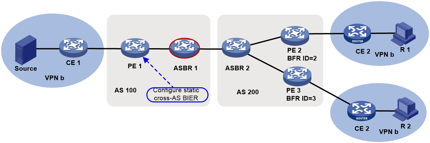
Restrictions and guidelines
In the same BIER sub-domain, the BFR ID ranges for different BFR neighbors cannot be overlapping. The configuration performed later does not take effect.
The configuration takes effect only on the BIRT of the local node and will not be advertised to other nodes.
The total number of BFR neighbors in all BIER sub-domains on the device cannot exceed 2000. The number of BFR IDs reachable through one BFR neighbor cannot exceed 256.
The maximum number of BFR IDs with the same priority reachable through one BFR neighbor is 4.
Procedure
1. Enter system view.
system-view
2. Enter BIER view.
bier
3. Enter sub-domain view.
sub-domain sub-domain-id ipv6
4. Specify a BFR neighbor and the BFR ID range of BIER edge devices that can be reached through the BFR neighbor.
bfr-neighbor { end-bier bierv6-sid | end-rgb msr6-sid | mpra ipv6-address } bfr-id bfr-id-start [ to bfr-id-end ] [ preference preference-value ]
By default, no BFR neighbor and BFR ID range are specified.
Configuring BGP-based cross-AS BIER
Enabling BIER for BGP
About this task
If BIER is enabled for BGP, BGP imports the BFR IDs and BFR prefixes from the BIER module and generates BGP routes carrying BIER information (excluding BFR ID range information).
The device generates a BGP IPv6 unicast route without BIER information and advertises the route to the BGP IPv6 unicast peers. The BGP IPv6 unicast route uses the locally configured MPRA and BFR prefix as the reachability prefix information of the NLRI field. The BGP IPv6 unicast route can guide the forwarding of BIER packets on devices that do not support BIER forwarding. If the peer capability bier command is also executed, the BGP routes generated by the local BFR prefix carry BIER path attributes can be advertised to the specified peer or peer group.
Restrictions and guidelines
You must perform this task before performing the following tasks:
· Enable the device to exchange routes with BIER path attributes with a peer or peer group.
· Enable BGP BFR prefix proxying.
· Enable BGP to redistribute routes from an IGP.
For more information about configuring BGP instances and address families, see BGP in Layer 3—IP Services Configuration Guide and Layer 3—IP Services Command Reference.
Procedure
1. Enter system view.
system-view
2. Enter BIER view.
bier
3. Enter sub-domain view.
sub-domain sub-domain-id ipv6
4. Configure the encapsulation type, BSL, and maximum SI.
encapsulation-type g-bier bsl bsl-value max-si max-si-value
By default, the encapsulation type, BSL, and maximum SI are not configured.
Enabling the device to exchange routes with BIER path attributes with a peer or peer group
About this task
With this feature configured, BGP will advertise received BIER information to the BIER module for it to generate a BIRT.
The device cannot exchange routes with BIER path attributes with peers or peer groups other than the specified peer or peer group.
Prerequisites
Before performing this task, you must enable BIER for BGP.
Procedure
1. Enter system view.
system-view
2. Enter BGP instance view.
bgp as-number [ instance instance-name ]
3. Enter BGP IPv6 unicast address family view.
address-family ipv6 [ unicast ]
4. Enable BGP to exchange routes with BIER path attributes with a peer or peer group.
peer { group-name | ipv4-address [ mask-length ] | ipv6-address [ prefix-length ] } capability bier
By default, the device cannot exchange routes with BIER path attributes with any peers or peer groups.
Enabling BGP BFR prefix proxying
Restrictions and guidelines
To avoid loops and ensure correct BIRT entries, perform this task only on one end of an EBGP session.
Prerequisites
Before performing this task, you must enable BIER for BGP.
Procedure
1. Enter system view.
system-view
2. Enter BGP instance view.
bgp as-number [ instance instance-name ]
3. Enter BGP IPv6 unicast address family view.
address-family ipv6 [ unicast ]
4. Enable BGP BFR prefix proxying.
bier bfr-prefix proxy
By default, BGP BFR prefix proxying is disabled.
Enabling BGP to redistribute the BIER information from an IGP
About this task
Perform this task to redistribute the BIER information from an IGP to the BGP routing table for distribution.
Restrictions and guidelines
The redistributed BIER information includes the BFR ID range information. The following rules apply to the inclusion of BFR ID range information when BGP routes generated based on the BIER information are advertised:
· If BGP BFR prefix proxying is not enabled:
¡ The BFR ID range information is not included when BGP routes are advertised to an IBGP peer.
¡ The BFR ID range information is included when BGP routes are advertised to an EBGP peer.
· If BGP BFR prefix proxying is enabled, the BFR ID range information is included when BGP routes are advertised to either an EBGP peer or an IBGP peer.
Prerequisites
Before performing this task, you must enable BIER for BGP.
Procedure
1. Enter system view.
system-view
2. Enter BGP instance view.
bgp as-number [ instance instance-name ]
3. Enter BGP IPv6 unicast address family view.
address-family ipv6 [ unicast ]
4. Enable BGP to redistribute the BIER information from an IGP.
import-bier isisv6 { process-id | all-processes }
By default, BGP does not redistribute the BIER information from an IGP.
After you redistribute the BIER information from all processes of a routing protocol by using the all-processes keyword, this command does not take effect on any processes of the protocol.
Display and maintenance commands for BIER
Execute the display commands in any view and the reset commands in user view.
|
Task |
Command |
|
Display BFR prefix information. |
display bier prefix [ prefix-ip ] [ sub-domain sub-domain-id [ bsl bsl-value ] ] |
|
Display BIER routing table information. |
display bier routing-table [ sub-domain sub-domain-id [ bsl bsl-value ] ] [ prefix prefix-ip ] [ verbose ] |
|
Display BIER sub-domain information. |
display bier sub-domain [ sub-domain-id ] |
|
Display the unicast routing protocols that registered with BIER. |
display bier protocol |
|
Display BIER packet statistics. |
In standalone mode: display bier forward ipv6 statistics slot slot-number In IRF mode: display bier forward ipv6 statistics chassis chassis-number slot slot-number |
|
Clear BIER packet statistics. |
In standalone mode: reset bier forward ipv6 statistics [ slot slot-number ] In IRF mode: reset bier forward ipv6 statistics [ chassis chassis-number slot slot-number ] |
BIER configuration examples
BIER is typically deployed as BIER-based MVPN. For configuration examples, see BIER-based MVPN configuration in IP Multicast Configuration Guide.
Troubleshooting BIER
BFR ID conflict
Symptom
The following log message is generated:
BIER/5/BIER_BFRID_CONFLICT_ACTIVE: -MDC=1; A BFR ID conflict exists. Address family=IPv6, Sub-domain=1, BFR ID=4, BFR prefixes=B::1,C::1.
Solution
To resolve the issue:
1. Identify the conflicting BFR edge devices through the BFR prefixes.
2. Modify the BFR ID for one of the two edge devices.
After the conflict is removed, the following log message is generated:
BIERRIB/5/BIER_BFRID_CONFLICT_CLEAR: -MDC=1; The BFR ID conflict was removed. Address family=IPv6, Sub-domain=1, BFR ID=4, BFR prefix=B::1.
