- Table of Contents
- Related Documents
-
| Title | Size | Download |
|---|---|---|
| 01-Text | 2.31 MB |
Introduction
The network management system is a lightweight Web-based network management platform that utilizes SmartMC (Intelligent Management Center) technology to centrally manage and maintain a large number of distributed network devices at the network edge.
The network management mode allows viewing the management information of all devices across the entire network and enables configuration of all devices from a holistic network perspective.
Network deployment
Deployment configuration can be performed in the following two ways:
· If the device has never been deployed, accessing the device via uweb.h3c.com will immediately take you to the network deployment page.
· If the device has already been deployed and you
need to modify the deployment parameters, you can click the "Network
Configuration Wizard" icon located at the top right corner of the Web
page.![]() In this case, if you wish to exit the
current configuration process due to unclear parameter values, you can click
the "Return to Homepage" icon
In this case, if you wish to exit the
current configuration process due to unclear parameter values, you can click
the "Return to Homepage" icon ![]() at the top right
corner of the Web page to go back to the UWEB network management page.
at the top right
corner of the Web page to go back to the UWEB network management page.
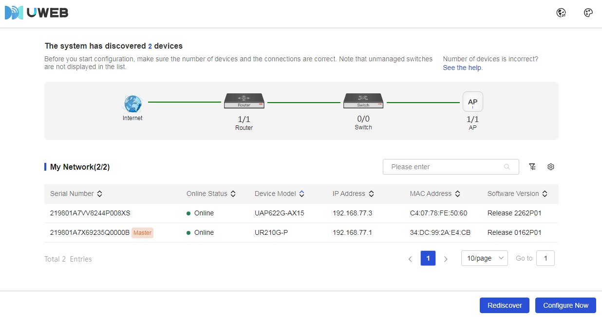
Device discovery
Procedure
Page Wizard: [Network Management/Discover Devices]
|
Discover devices on the network and query device information in "My Network," including serial number, online status, device model, IP address, MAC address, and software version. |
|
Parameters
The meanings of the parameters on the page are shown in the table below.
Table 1 Parameter description
|
Parameter |
Description |
Application scenarios |
|
Rediscover |
Refresh the status information of the entire network and rediscover devices in the network |
Update Network Status |
|
Start Configuration |
Configure the deployment for the entire network |
- |
|
Advanced Search |
Use the <> button to filter device information in the network by the serial number, online status, device model, IP address, MAC address, and software version with matching conditions of "contains," "exact match," and "does not contain." |
- |
|
Column Sorting |
Use the <> button to display device information in the network based on different combinations of serial number, device name, device model, IP, MAC, and software version. |
- |
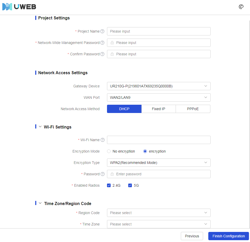
Deployment Settings
Procedure
Page Wizard: [Network Management/Deployment Configuration]
|
Perform deployment configuration for the entire network management, including: project settings, internet settings, Wi-Fi settings, time zone, etc. |
|
|
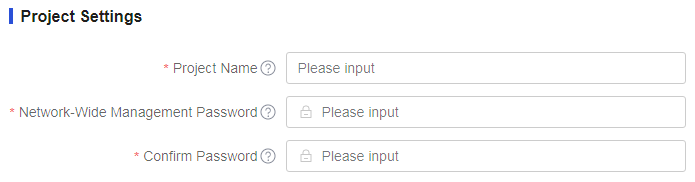
Set up the project |
|
|
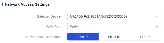
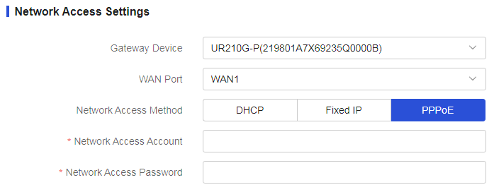
Configure internet settings, with the following connection methods: · Using "DHCP" · Using "Static IP" · Using "PPPoE" |
· Achieve internet access using "DHCP"
· Achieve internet access using "Static IP"
· Achieve internet access using "PPPoE"
|
|
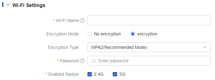
Configure Wi-Fi settings, with encryption methods including: · Using "No Encryption" · Using "Encryption" |
· Using "No Encryption"
· Using "Encryption"
|
|
Set the time zone and region |
|


Parameters
The meanings of the parameters on the page are shown in the table below.
Table 2 Parameter description
|
Parameter |
Description |
|
Item |
The name of the project, which must be 1-20 characters long, cannot start with digits or spaces, and does not support the characters “?”,“'”,“"”,“\”. |
|
Device Management Password |
The management password for the device, which must be 10-63 characters long and can only include digits, letters, or English symbols (excluding spaces, “?”,“'”,“"”,“\”). The password must contain at least two types of combinations and cannot include the sequence or reverse sequence of 'admin'. |
|
Confirm Password |
Project Confirmation Password, when entering the confirmation password, ensure that it matches the device management password. |
|
Gateway Device |
The gateway device in the network, connecting different networks to enable intercommunication. |
|
WAN Port |
The WAN port on the gateway device, used for connecting to the Internet. |
|
Internet access modes |
Connecting to the Internet, including DHCP, static address, PPPoE: · DHCP is a network connection method that dynamically allocates IP addresses. When a device connects to the network, it sends a request to the DHCP server, which dynamically assigns network parameters such as IP address, subnet mask, gateway, and DNS server, allowing the device to quickly connect to the network and obtain the necessary IP profile. · A static address refers to a manually configured static IP address, subnet mask, gateway, and DNS server, which do not change with the device's connection status. · PPPoE is a protocol for establishing a point-to-point connection over Ethernet, commonly used for authentication and dial-up connections in broadband access environments. When accessing a wide area network (WAN) using PPPoE, users must provide specific account and password information, and the router will perform the dial-up connection for Internet access. |
|
IP address |
IP Address for the Device's Wide Area Network Access |
|
Subnet mask |
IP Address Mask or Mask Length |
|
Gateway |
Gateway Address for the Device's Wide Area Network Access |
|
DNS |
DNS Server Address for the Device's Wide Area Network Access |
|
Internet Account |
Username used for authentication, provided by the carrier. |
|
Internet Password |
Password used for authentication, provided by the carrier. |
|
Wi-Fi Name |
Name of the wireless network service, which must be 1-32 characters long and cannot contain special characters “'”,“#”,“"”,“?”. |
|
Encryption Algorithm |
Encryption method for the wireless service. When configuring this parameter, you can select between no encryption and encryption as needed. |
|
Password |
Password for the wireless network service, with a length of 8-63 bytes. |
|
Effective Radio Frequency |
The wireless frequency used, any combination of the following values: · 2.4G · 5G |
|
Time Zone/Region |
Geographical area and time zone of the device. |
Dashboard
Dashboard
Procedure
Page Wizard: [Network Management/Overview]
|
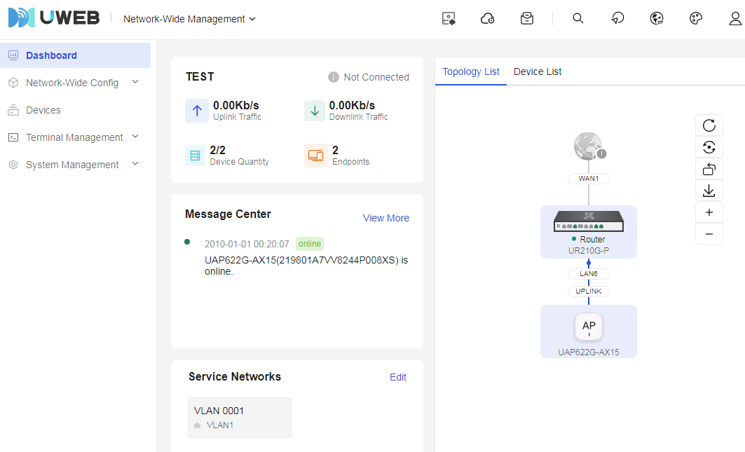
The overview will display the operational status of the entire network system, including traffic measurement, message information, service network, topology list, device list, and other information. |
|
Parameters
The meanings of the parameters on the page are shown in the table below.
Table 3 Parameter description
|
Parameter |
Description |
|
Upstream. |
Statistics of upstream traffic in the network, which is the amount of data sent from customer equipment to the Internet |
|
Downstream. |
Statistics of downstream traffic in the network, which is the amount of data transmitted from the Internet to customer equipment |
|
Number of Devices |
Statistics of the number of devices in the network |
|
Number of Terminals |
Statistics of the number of terminals in the network |
|
Message Center |
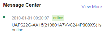
Messages in the overall network management system, for detailed information please see the Message Center |
|
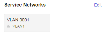
Service network |
Types of service networks in the overall network management system, including wired and wireless services, for detailed information please see Service Network |
|
Topology List |
Device topology information, for detailed information please see the Topology List |
|
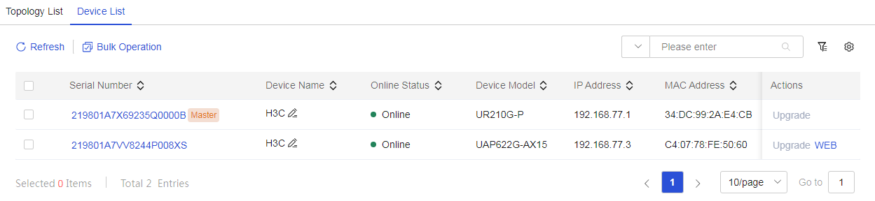
Device List |
Device list information, including serial number, device name, online status, MAC, IP, software version, device model, and operations, for detailed information please see the Device List |
Message Center
Procedure
Page Wizard: [Network Management/Overview/Message Center]
|
View the latest reported brief messages on the network |
|
Parameters
The meanings of the parameters on the page are shown in the table below.
Table 4 Parameter description
|
Parameter |
Description |
|
More |
View the detailed information recently reported on the network |
Service network
Procedure
Page Wizard: [Network Management/Overview/Service Network]
|
View the business configuration in the network |
|
Parameters
The meanings of the parameters on the page are shown in the table below.
Table 5 Parameter description
|
Parameter |
Description |
|
Edit |
Go to the service network page to add business configurations |
Topology list
Procedure
Page Wizard: [Network Management/Overview/Topology List]
|
View the specific network topology |
|

Parameters
The meanings of the parameters on the page are shown in the table below.
Table 6 Parameter description
|
Parameter |
Description |
|
Refresh |
Update topology data in the network |
|
Restore |
Restore the arrangement of the topology structure in the network to the system default state, with the topology arranged from top to bottom |
|
Flip |
Arrange the topology structure in the network from left to right |
|
Download |
Download the topology structure in the network to the local system, saving the file in PNG format |
Device list
Procedure
Page Wizard: [Network Management/Overview/Device List]
|
· View device list information · Select the check box in the device list, click the batch operation button, and execute the batch operation on the selected devices. |
|
Parameters
Table 7 Parameter description
|
Parameter |
Description |
Application scenarios |
|
Refresh |
Update the data information in the device list |
Users need to obtain the latest data from the device list |
|
Batch Operations |
Batch operations include: Restart, Upgrade, Reset: · Restart: Execute the restart operation on the selected devices · Upgrade: Execute the upgrade operation on the selected devices · Reset: Execute the reset operation on the selected devices |
When multiple devices require the same operation, performing the same action on each device can be cumbersome. At this point, you can use the batch operation function to perform operations on multiple devices, saving effort |
|
Advanced Search |
Using the <> advanced search function, filter device information in the device list by using the matching criteria "Contains," "Exact Match," and "Does Not Contain," based on device serial number, device name, online status, device model, IP, MAC, or software version |
When there is a large amount of device information in the device list, users can quickly and accurately filter the required device information using the filter function, improving work efficiency and accuracy |
|
Column Sorting |
Using the <> function, display device information in the device list based on different combinations of serial number, device name, online status, device model, IP, MAC, or software version |
- |
Network configuration
Service network
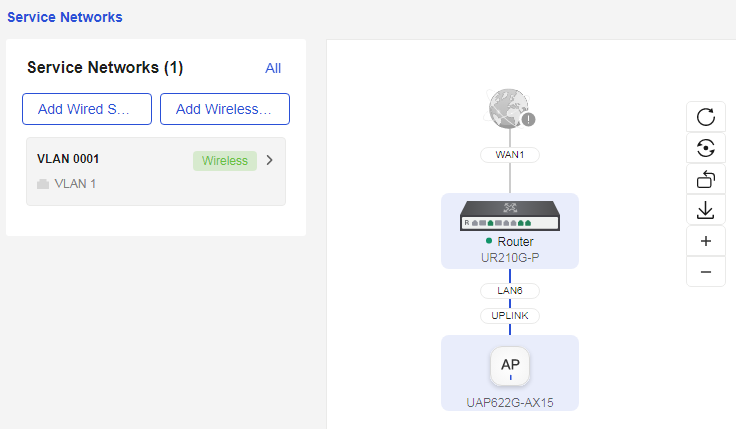
Add a wired service network
Procedure
Page Wizard: [Network Management/Network Configuration/Service Network/Add Wired Service Network]
|
Configure the wired service network |
|
|
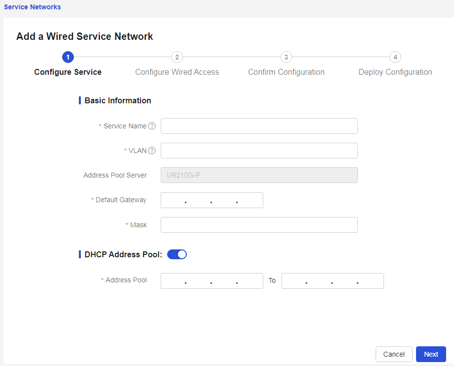
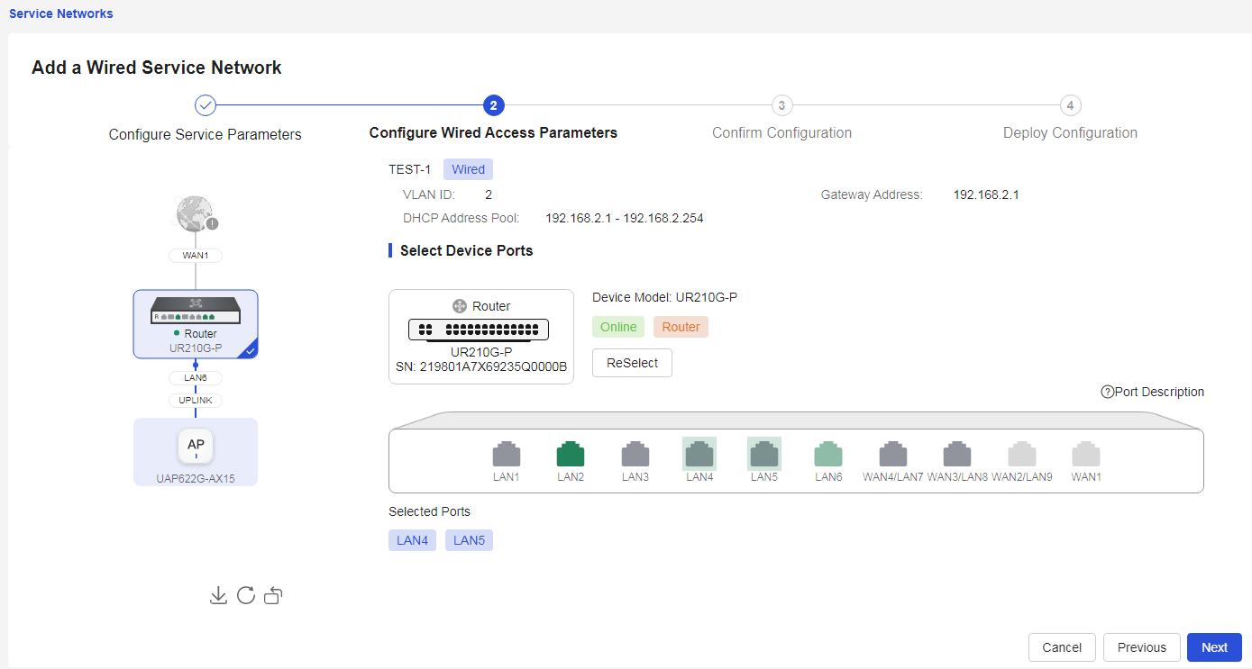
Select "Add Wired Service Network" to add wired service network configuration and set "Wired Service Parameters" 1. In the "Service Name" configuration item, enter the service name 2. In the "VLAN" configuration item, enter the service VLAN, with a value range of 1 to 4000 3. In the "Address Pool Server" configuration item, the system automatically selects the device 4. In the "Default Gateway" configuration item, enter the address of the service gateway 5. In the "Mask" configuration item, enter the subnet mask 6. In the "DHCP Address Pool" configuration item, select to enable/disable the DHCP address pool function 7. If the "DHCP Address Pool" function is enabled, in the "Address Pool" configuration item, enter the range of IP addresses to be allocated 8. Click < Next > to enter the "Wired Access Settings" page |
|
|
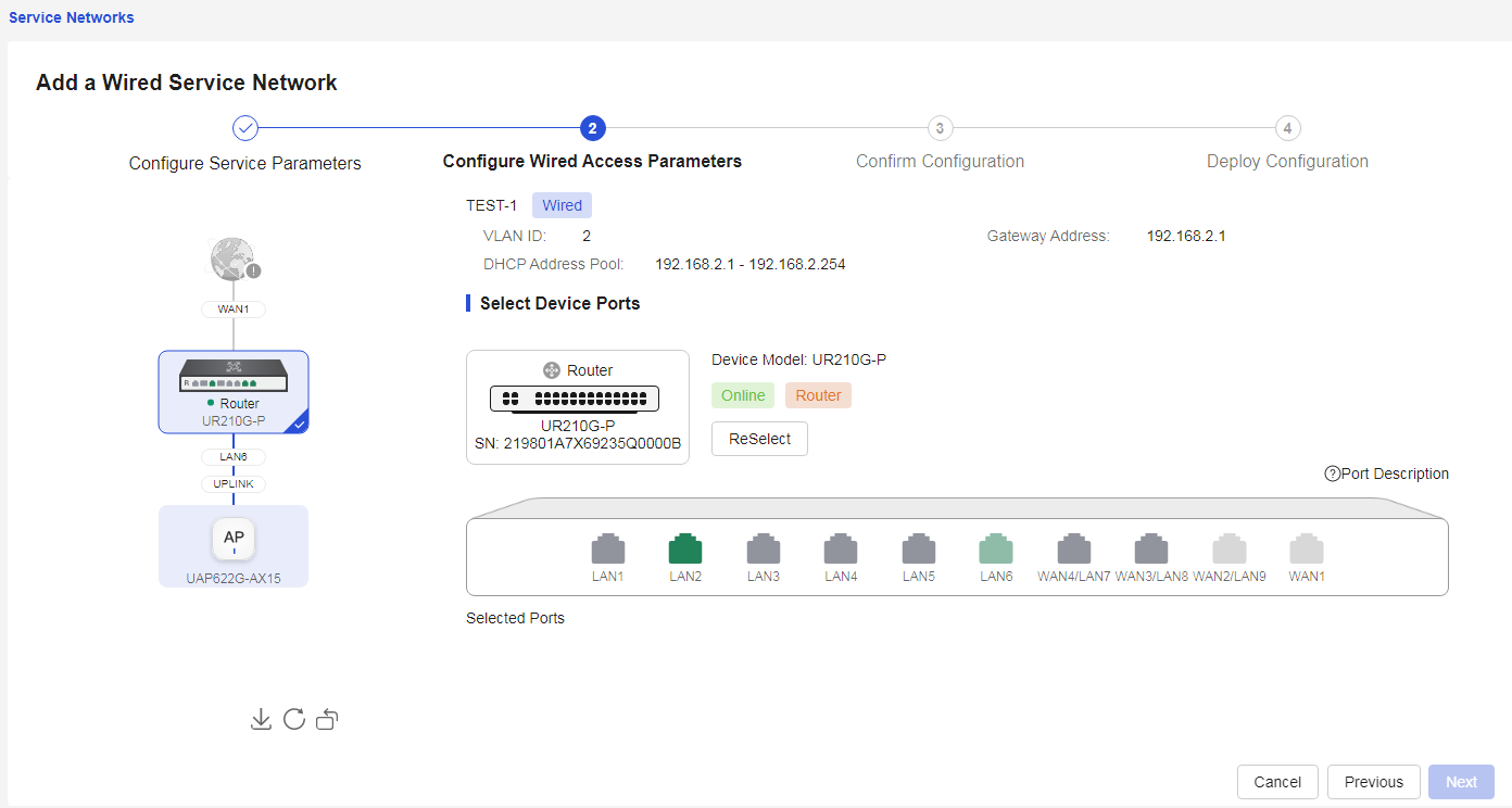
For "Wired Access Settings" 1. Click to select the device that the wired terminal is preparing to access from the left topology 2. On the device faceplate, click the port for the wired network terminal planning to access 3. After confirming the accuracy, click < Next > button to enter the "Configuration Dispatch Confirmation" configuration page |
· Set up wired access
· Select the device that the wired terminal is preparing to access
· Select the port for the wired network terminal planning to access
|
|
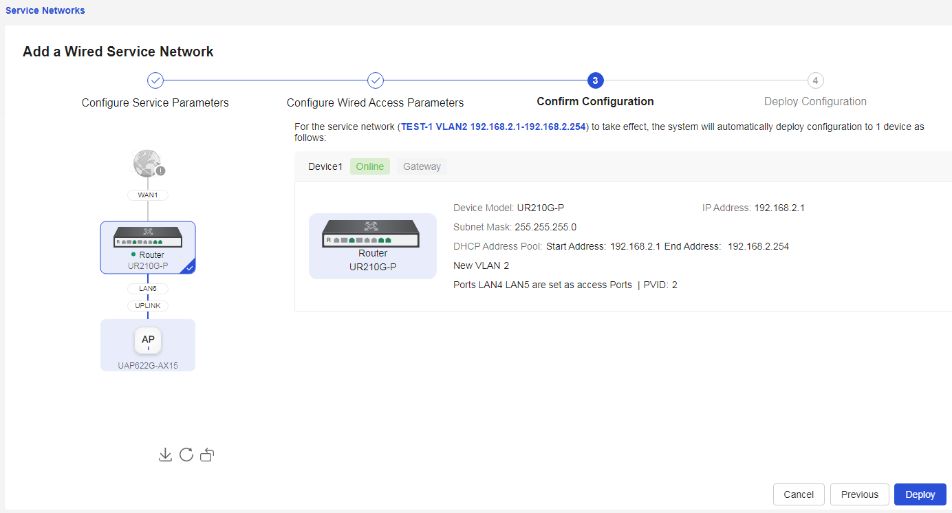
"Configuration Dispatch Confirmation", check the service configuration, and after confirming it is correct, click < Confirm and Dispatch > button to perform the configuration dispatch. Please do not close this page during the dispatch process, and be patient |
|
|
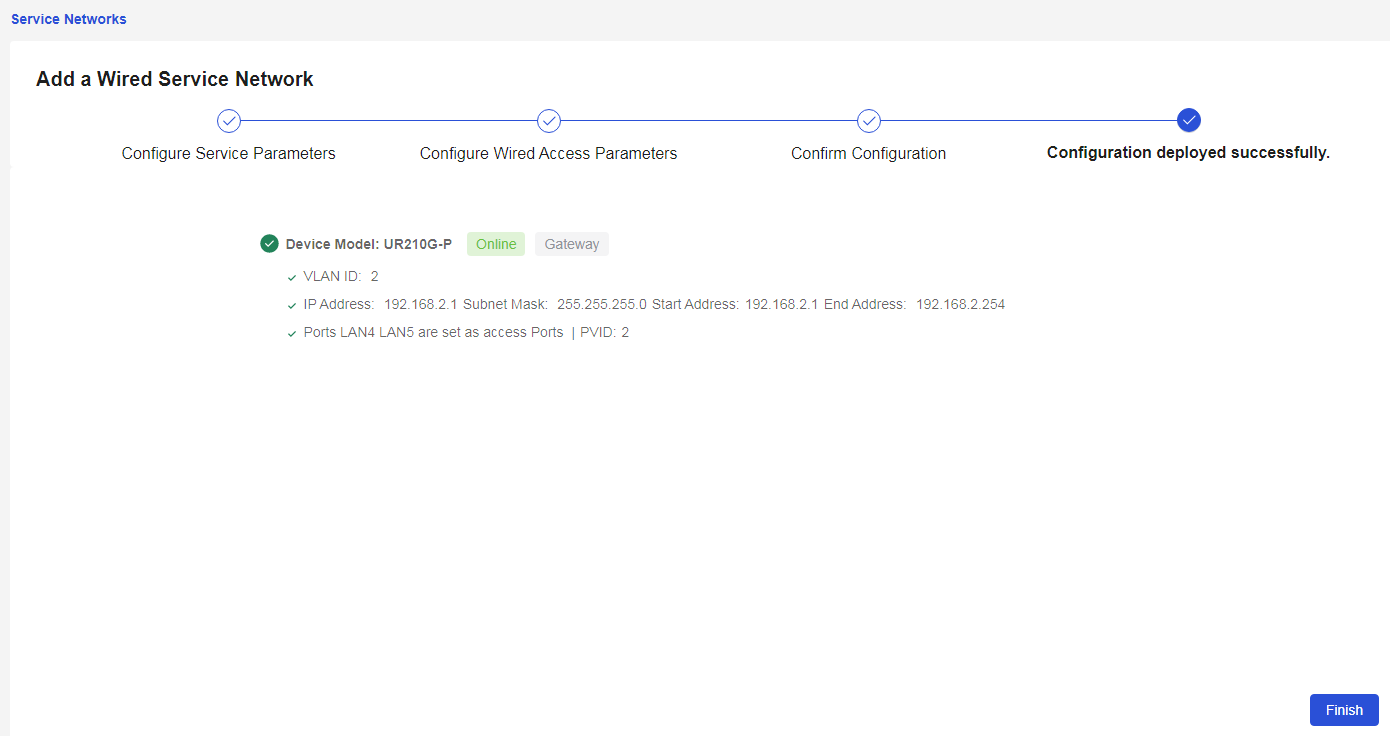
"Configuration Dispatch", after the configuration dispatch is successful, click < Finish > button to complete the wired network service configuration |
|


Parameters
The meanings of the parameters on the page are shown in the table below.
Table 8 Parameter description
|
Parameter |
Description |
|
Add Wired Service Network |
Add Wired Service Network Configuration |
|
Service name. |
Chinese, letters, digits, underscores, spaces, and -; length less than 255; cannot be all spaces; cannot be "IPTV" |
|
VLAN |
The ID number of this VLAN interface, with values from 1 to 4000 |
|
Address Pool Server |
The server that manages and allocates IP addresses to client devices; the system automatically selects the device |
|
Default Gateway |
The default gateway for the device accessing the wide area network (WAN) |
|
Subnet Mask |
The mask of the IP address or the mask length |
|
DHCP address pool |
Whether to enable the DHCP address pool function. If enabled, the device will dynamically allocate IP addresses to client devices connected to it (e.g., computers connected to the device) |
|
IP pool |
The range of IP addresses allocated by the DHCP server address pool, including the starting IP address and the ending IP address |
|
Reselect |
Re-select the access port |
Add a wireless service network
Procedure
Page Wizard: [Network Management/Network Configuration/Service Network/Add Wireless Network]
|
Configure the wireless service network |
|
|
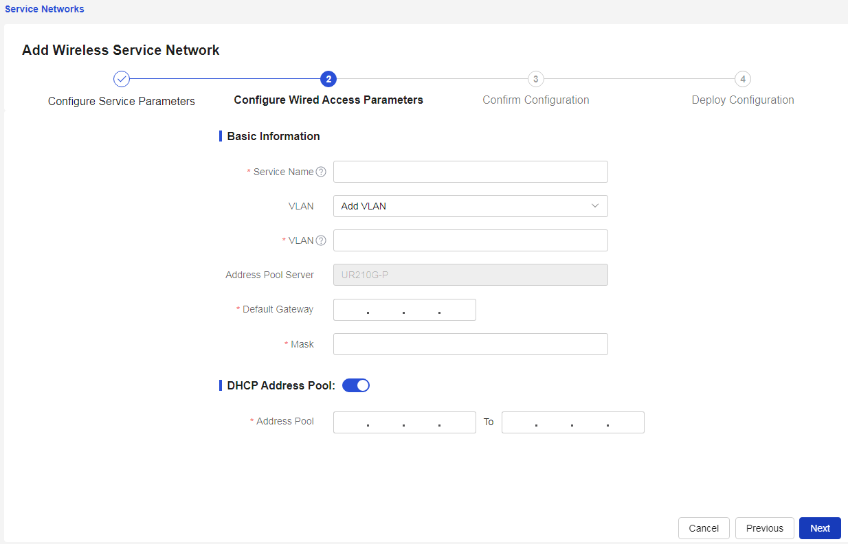
Select "Add New Wireless Service Network" to add the wireless service network configuration and set the wireless service parameters: 1. In the "Wi-Fi Name" configuration item, enter the name of the wireless service 2. In the "Operating State" configuration item, enable or disable the operating state of the wireless service based on actual business needs 3. In the "Encryption Method" configuration item, enable or disable wireless encryption based on actual business needs 4. In the "Encryption Type" configuration item, select the encryption type for the wireless service from the drop-down menu, including WPA/WPA2 (compatibility mode), WPA2 (recommended mode), or WPA3 (secure mode) 5. In the "Password" configuration item, enter the Wi-Fi password 6. In the "Effective Radio Frequency" configuration item, select the effective frequency band using the check box 7. In the "MLO" configuration item, select whether to enable the MLO function based on actual business needs 8. In the "Hide Wi-Fi" configuration item, select whether to hide the Wi-Fi based on actual business needs. When the button is enabled, the name of the wireless network will be hidden, and wireless terminals must manually enter the Wi-Fi name to join the network 9. In the "User Speed Limit" configuration item, select whether to limit user speed based on actual business needs 10. After confirming everything is correct, click the <Next> button to enter the "Wired Access Settings" configuration page to set up wired access |
|
|
For "Wired Access Settings" 1. In the "Service Name" configuration item, enter the service name 2. In the "VLAN" configuration item, you can select an already configured VLAN from the drop-down menu or select to add a new VLAN 3. If "VLAN" is to add a new VLAN, enter the service VLAN in the "VLAN" configuration item, with a value between 1 and 4000 4. In the "Address Pool Server" configuration item, the system automatically selects the device 5. In the "Default Gateway" configuration item, enter the address of the service gateway 6. In the "Mask" configuration item, enter the subnet mask 7. In the "DHCP Address Pool" configuration item, enable or disable the "DHCP Address Pool" function based on actual business needs 8. If you enable the "DHCP Address Pool" function, enter the range of IP addresses to be allocated in the "Address Pool" configuration item 9. After confirming everything is correct, click the <Next> button to enter the "Configuration Delivery Confirmation" tab |
|
|
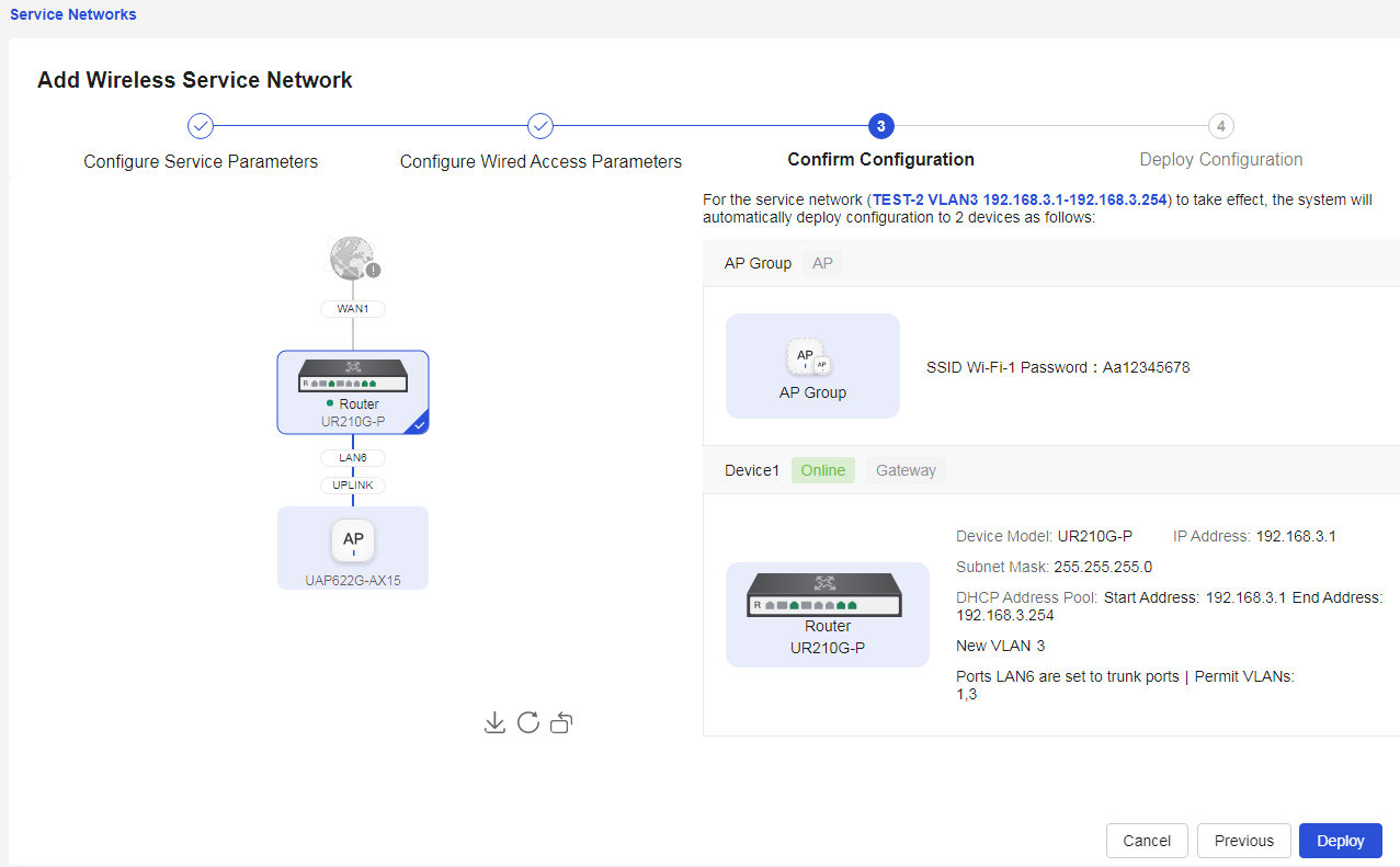
In "Configuration Delivery Confirmation," check the service configuration, and after confirming it is correct, click the <Confirm and Deliver> button to proceed with the configuration delivery. Please do not close this page during the configuration delivery and wait patiently |
|
|
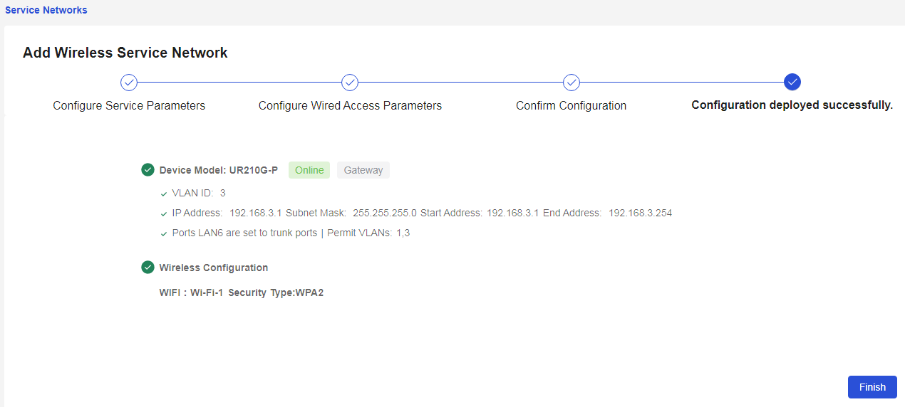
After the configuration delivery is successful, click the <Complete> button to finish the wireless network service configuration |
|

Parameters
The meanings of the parameters on the page are shown in the table below.
Table 9 Parameter description
|
Parameter |
Description |
|
Add Wireless Business Network |
Add Wireless Network Service |
|
Wi-Fi Name |
The name of the wireless network service, with a length of 1-32 characters, cannot contain special characters such as “'”, “#”, “"”, “?” |
|
Work Status |
Enable or disable the wireless network service based on actual business needs |
|
Encryption Algorithm |
Enable or disable the wireless network encryption function based on actual business needs |
|
Encryption Type |
Encryption method for the wireless service; when configuring this parameter, you can select as needed: · WPA/WPA2 (Compatible Mode): Provides high security, using a hybrid encryption method of WPA and WPA2 · WPA2 (Recommended Mode): A highly secure encryption method, applicable to devices that support WPA2, primarily connects through password input but also widely supports 802.1X authentication, suitable for home and small office networks · WPA3 (Secure Mode): The latest secure encryption method, more secure than WPA2, applicable to devices that support WPA3, offering multiple connection methods, including traditional password input, QR code connection, and enhanced open connection, suitable for home, small office networks, and public network environments |
|
Password |
Set the password for the wireless service |
|
Effective Radio Frequency |
Wireless frequency used by the wireless service |
|
MLO |
The MLO function requires the device to support two frequency bands of “802.11be (Wi-Fi 7)”. After enabling this function, the AP can coordinate multiple links across different frequency bands, achieving multifrequency connections with terminals, increasing bandwidth and reducing latency. Note: After enabling the MLO function, some terminals may fail to connect due to compatibility issues. In such cases, it is recommended to disable the MLO function |
|
Hide Wi-Fi |
Select whether to hide Wi-Fi: · If you turn off hiding Wi-Fi, when wireless clients search for local accessible wireless networks, they will detect the broadcast Wi-Fi and can establish a connection · If you enable hiding Wi-Fi, the administrator needs to inform the client of the Wi-Fi name, then the client can connect to the wireless network based on the Wi-Fi name |
|
User rate limit |
The user bandwidth limiting function can restrict excessive bandwidth consumption by individual users, ensuring that all connected users can normally use network services |
|
Per User Bandwidth Limit |
Each user associated with this SSID operates according to the set bandwidth limit value. For example, if the per-user bandwidth limit rate is 1 Mbps, then all users associated with this SSID will be limited to 1 Mbps. |
|
Average Distribution Among All Users |
All users associated with this SSID evenly share the set value, and each user's bandwidth limit will dynamically change based on the current number of users associated with the SSID. For example, if the limit rate value is M and the number of associated users is N, then each user will be limited according to M/N |
|
Uplink Rate Limit |
Limit the user's upstream traffic |
|
Downlink Rate Limit |
Limit the user's downstream traffic |
|
Limit Rate |
Set the user's traffic limit rate, in Kbps |
|
Service name. |
Chinese letters, English letters, digits, underscores, spaces, and -; length less than 255; cannot be all spaces; cannot be “IPTV” |
|
VLAN |
The ID number of this VLAN interface, with a value between 1 and 4000 |
|
Address Pool Server |
The server that manages and allocates IP addresses to client devices, with the system automatically selecting the device |
|
Default Gateway |
The default gateway for the device accessing the wide area network |
|
Subnet Mask |
IP address mask or mask length |
|
DHCP address pool |
Whether to enable the DHCP address pool function. If this function is enabled, the device will dynamically allocate IP addresses to client devices connected to it (e.g., computers connected to the device) |
|
IP pool |
The range of IP addresses allocated by the DHCP server address pool, including the starting IP address and ending IP address |
Wireless services
WLAN technology is one of the hot topics in today's communication field. By using WLAN solutions, network operators and enterprises can provide convenient wireless access services to users, which mainly include:
· Establishing a wireless network using devices with wireless local area network capabilities, allowing users to access the local area network or the Internet through this network;
· Providing secure wireless network access services using different authentication and encryption methods;
· Enabling users to move freely within the network coverage area, completely freeing them from wired constraints.
Procedure
Page Wizard: [Network Management/Network Configuration/Wireless Services]
|
Configure the wireless network |
|
|
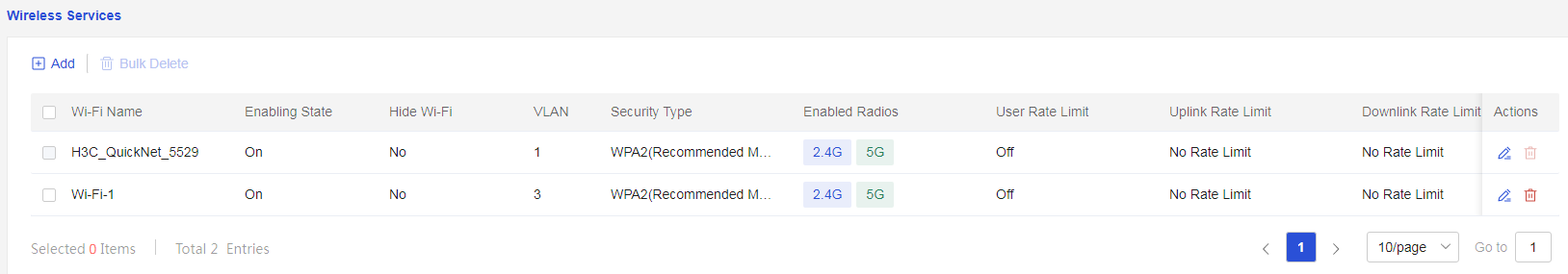
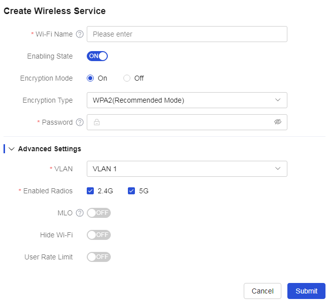
Click<Add>button to enter the “Add Wireless Service” tab and set up the wireless service: 1. In the “Wi-Fi Name” configuration item, enter the name of the Wi-Fi 2. In the “Operating State” configuration item, open or close the wireless service 3. In the “Encryption Method” configuration item, enable or disable wireless encryption based on actual business needs 4. In the “Encryption Type” configuration item, select the encryption type for the wireless service from the drop-down menu, including WPA/WPA2 (compatible mode), WPA2 (recommended mode), or WPA3 (secure mode) 5. In the “Password” configuration item, enter the Wi-Fi password 6. In the “VLAN” configuration item, select the created VLAN or add a new wireless service VLAN from the drop-down menu 7. In the “Effective Radio Frequency” configuration item, select the effective frequency band using the check box 8. In the “MLO” configuration item, select whether to enable the MLO function based on actual business needs 9. In the “Hide Wi-Fi” configuration item, if the button is in the off position, it means Wi-Fi is not hidden; if the button is in the on position, it means Wi-Fi is hidden, and the name of the wireless network will be concealed, requiring manual addition of the network when connecting with wireless terminals 10. In the “User Speed Limit” configuration item, select whether to limit user speed based on actual business needs 11. After confirming everything is correct, click<Submit>button to add the service template |
|
|
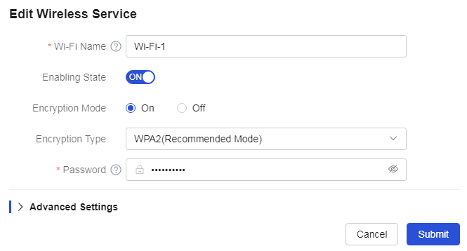
In the Wi-Fi list, click the corresponding<Edit>button for the specified Wi-Fi to pop up the edit wireless service dialog box and edit the wireless service |
|
|
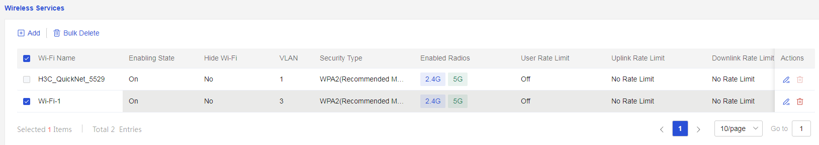
In the Wi-Fi list, select the wireless service, click the corresponding<Delete>button, or click<Batch Delete>button, confirm everything is correct, and then click<Confirm>button to complete the deletion |
|
Parameters
The meanings of the parameters on the page are shown in the table below.
Table 10 Parameter description
|
Parameter |
Description |
|
Add |
Add New Wireless Network Service |
|
Wi-Fi Name |
The name of the wireless network service, with a length of 1-32 characters, cannot contain special characters such as “'”, “#”, “"”, and “?”. |
|
Work Status |
Enable or disable the wireless network service based on actual business needs. |
|
Encryption Algorithm |
Enable or disable the wireless network encryption function based on actual business needs. |
|
Encryption Type |
Encryption method for the wireless service. When configuring this parameter, you can select as needed: · WPA/WPA2 (Compatible Mode): Provides high security using a hybrid encryption method of WPA and WPA2. · WPA2 (Recommended Mode): A higher security encryption method used for devices that support WPA2, primarily connecting via password input but also widely supporting 802.1X authentication, suitable for home and small office networks. · WPA3 (Secure Mode): The latest secure encryption method, more secure than WPA2, used for devices that support WPA3. It offers multiple connection methods, including traditional password input, QR code connection, and enhanced open connection, suitable for home, small office networks, and public network environments. |
|
Password |
Set the password for the wireless service. |
|
VLAN |
The ID number of this VLAN interface, with a value range of 1 to 4000. |
|
Effective Radio Frequency |
Wireless frequency used by the wireless service. |
|
MLO |
MLO function requires the device to support “802.11be (Wi-Fi 7)” on two frequency bands. After enabling this feature, the AP can coordinate multiple links across different frequency bands to achieve multiband connections with terminals, increasing bandwidth and reducing latency. Note: After enabling the MLO function, some terminals may fail to connect due to compatibility issues. If this occurs, it is recommended to disable the MLO function. |
|
Hide Wi-Fi |
You can select whether to hide the Wi-Fi. When the button is turned on, the name of the wireless network service will be hidden. Wireless terminals connecting to the wireless network will need to manually search for the name of the wireless network service. |
|
User rate limit |
The user bandwidth limitation feature can restrict excessive bandwidth consumption by individual users, ensuring that all connected users can normally use network services. |
|
Per User Bandwidth Limit |
Each user associated with this SSID operates according to the set bandwidth limit value. For example, if the per user limit rate value is 1Mbps, then all users associated with this SSID will be limited to 1Mbps. |
|
Average Sharing Among All Users |
All users associated with this SSID share the set value equally, and each user's bandwidth limit will dynamically change based on the current number of users associated with the SSID. For example, if the limit rate value is M and the number of users is N, each user will be limited at M/N. |
|
Uplink Rate Limit |
Limit the user's upstream traffic. |
|
Downlink Rate Limit |
Limit the user's downstream traffic. |
|
Limit Rate |
Set the user's traffic limit rate, with a unit of Kbps. |
|
Edit |
Edit wireless network configuration. |
|
Delete |
Delete a single wireless service configuration. |
|
Bulk Delete |
Batch delete multiple wireless service configurations. |
Radio configuration
Procedure
Page Wizard: [Network Management/Network Configuration/Radio Frequency Configuration]
|
Configure radio frequency (RF) parameters |
|
Parameters
The meanings of the parameters on the page are shown in the table below.
Table 11 Parameter description
|
Parameter |
Description |
|
Region code |
Select the corresponding zone code based on the device's location |
|
Increase Radio Frequency (RF) |
If there are tri-band devices in the network, you can differentiate the configuration of the second 5G radio frequency (5G-2) by increasing the RF function |
|
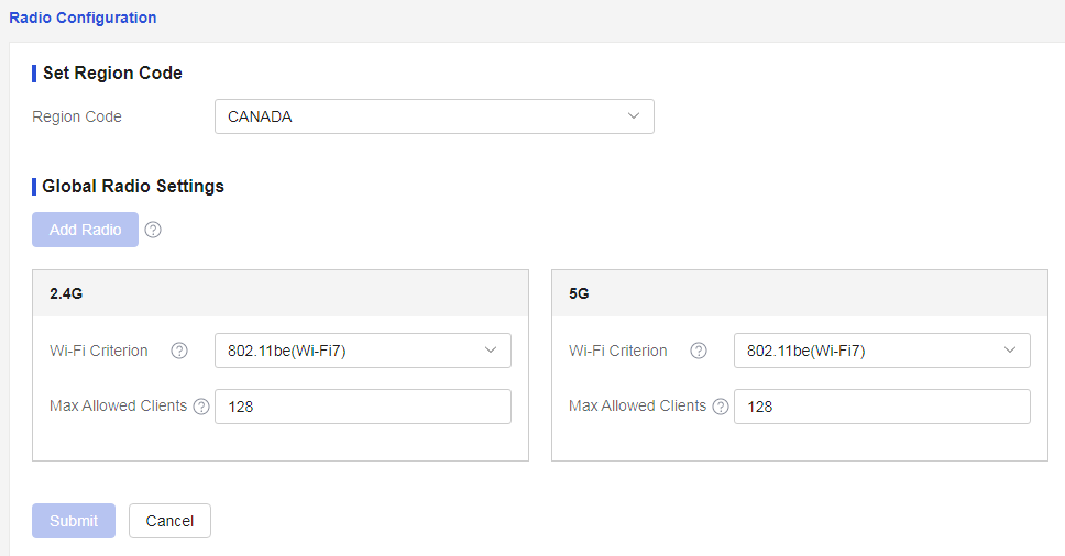
Wi-Fi Mode |
Configure the Wi-Fi standard, with values as follows: · Compatibility mode allows different generations of Wi-Fi devices to communicate with each other, providing backward compatibility between new and old standards · 802.11ax (Wi-Fi6), suitable for high-density home, enterprise, and public network environments, such as conference centers, stadiums, and shopping malls · 802.11be (Wi-Fi7), suitable for high bandwidth and low latency scenarios, such as 8K video streams, VR/AR, enterprise environments, and smart cities |
|
Max Client Quantity |
The maximum number of terminal equipment (TE) that the wireless network access point (NAP) can support simultaneously |
Allowlist and denylist
Procedure
Page Wizard: [Network Management/Network Configuration/Black and White Lists]
|
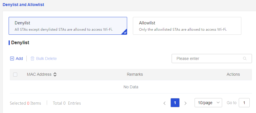
Configure the denylist/allowlist |
|
|
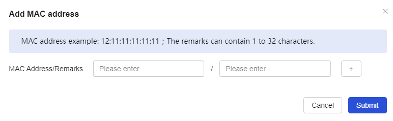
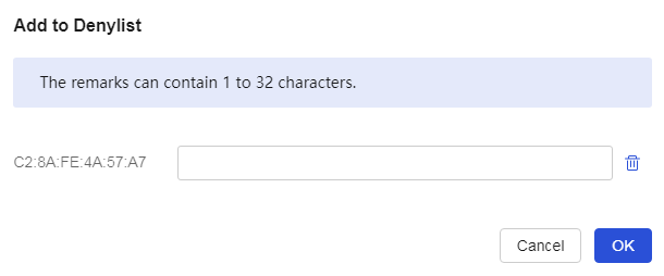
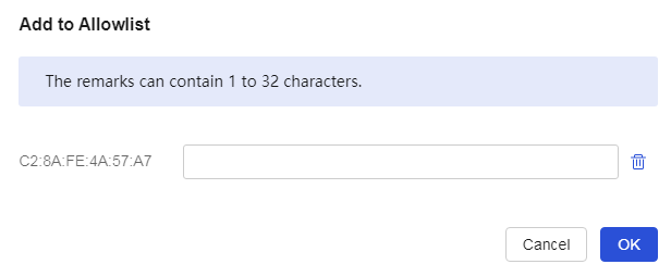
· In the "Wireless Denylist" configuration item, click "Add" to add a new MAC address and notes for the denylist. · In the "Wireless Allowlist" configuration item, click "Add" to add a new MAC address and notes for the allowlist. |
|
Parameters
The meanings of the parameters on the page are shown in the table below.
Table 12 Parameter description
|
Parameter |
Description |
|
Denylist |
Deny specific MAC addresses from accessing Wi-Fi |
|
Allowlist |
Allow only specific MAC addresses to access Wi-Fi |
|
Add |
Add MAC addresses and notes to the denylist/allowlist |
|
Edit |
Modify MAC addresses and notes in the denylist/allowlist |
|
Bulk Delete |
Bulk delete MAC addresses and notes from the denylist/allowlist |
WLAN optimization
Intelligent network optimization
Procedure
Page Wizard: [Network Management/Network Configuration/Wireless Optimization/Intelligent Network Optimization]
|
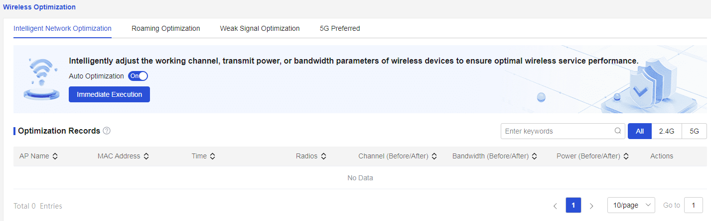
Perform intelligent network optimization for wireless networks |
|
Parameters
The meanings of the parameters on the page are shown in the table below.
Table 13 Parameter description
|
Parameter |
Description |
|
Automatic Optimization |
Once enabled, the system will monitor radio equipment in real-time and optimize locally when appropriate to ensure that wireless services are always in optimal condition. After optimization is complete, you can view the optimization records. If terminal equipment (TE) is in service, the system will temporarily stop automatic optimization. |
|
Run Now |
The system will immediately perform a wireless network optimization based on the current network environment to fully enhance wireless performance. |
|
Optimization Records |
Intelligent Wireless Network Optimization Records: · No optimization records will be generated if there are no APs in the network or if no optimization has been performed. · Only the most recent optimization record for each AP will be displayed. Click to view historical optimization records for more information. · Each AP can display a maximum of 10 optimization records per radio frequency (RF). |
|
All |
2.4G and 5G Wireless Network Optimization Records |
|
2.4G |
2.4GHz Wireless Network Optimization Records |
|
5G |
5GHz Wireless Network Optimization Records |
Roaming optimization
Procedure
Page Wizard: [Network Management/Network Configuration/Wireless Optimization/Roaming Optimization]
|
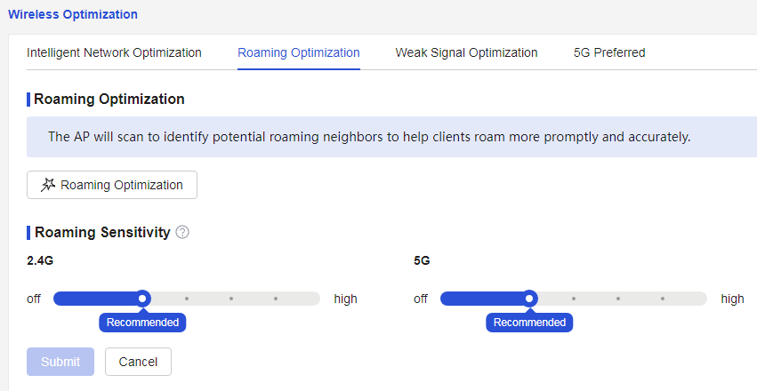
Optimize the roaming function |
|
Parameters
The meanings of the parameters on the page are shown in the table below.
Table 14 Parameter description
|
Parameter |
Description |
|
Roaming Optimization |
The AP will scan for potential roaming neighbors to help the terminal roam more timely and accurately. This process will last about 2 minutes. |
|
Roaming sensitivity |
Adjust the roaming sensitivity of the terminal. It can modify the signal strength threshold for initiating roaming. In densely deployed scenarios, roaming sensitivity can be appropriately increased; conversely, in sparsely deployed scenarios, roaming sensitivity can be decreased. |
|
Recommended |
Recommended Configuration for Roaming Sensitivity |
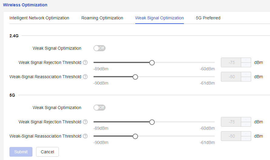
Weak signal optimization
Procedure
Page Wizard: [Network Management/Network Configuration/Wireless Optimization/Weak Signal Optimization]
|
Optimization of weak wireless signals |
|
Parameters
The meanings of the parameters on the page are shown in the table below.
Table 15 Parameter description
|
Parameter |
Description |
|
Weak Signal Optimization |
Optimize for weak wireless signals |
|
Weak Signal Rejection Threshold |
Set the threshold value to prohibit weak signal access. Clients not connected to wireless services will be unable to connect if the signal strength falls below the threshold value; if the threshold value is too high, it may cause difficulties for clients to connect. |
|
Weak Signal Reassociation Threshold |
Set the weak signal re-association threshold value. Clients already connected to wireless services will be kicked offline if the signal strength falls below the threshold value. Some special clients may experience an inability to connect after being kicked offline multiple times; please exercise caution when enabling this function for such clients. |
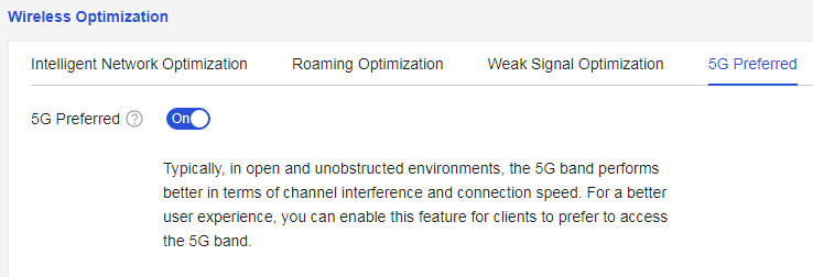
5G priority
Procedure
Page Wizard: [Network Management/Network Configuration/Wireless Configuration/Wireless Optimization]
|
Select to enable or disable the "5G Priority" function |
|
Parameters
The meanings of the parameters on the page are shown in the table below.
Table 16 Parameter description
|
Parameter |
Description |
|
5G Priority |
After enabling this function, the terminal will be guided to prioritize access to the 5G frequency band for a better user experience. |
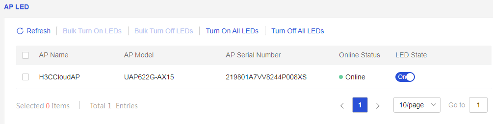
AP LEDs
Procedure
Page Wizard: [Network Management/Network Configuration/AP LED]
|
Open or close the LED on the AP |
|
Parameters
The meanings of the parameters on the page are shown in the table below.
Table 17 Parameter description
|
Parameter |
Description |
|
Batch Turn On LEDs |
Select the check box in front of the corresponding AP, select to batch turn on lights, and open the LEDs on the corresponding AP. |
|
Batch Turn Off LEDs |
Select the check box in front of the corresponding AP, select to batch turn off lights, and close the LEDs on the corresponding AP. |
|
Turn On All LEDs |
Open the LEDs on all APs. |
|
Turn Off All LEDs |
Close the LEDs on all APs. |
|
Refresh |
Refresh AP LED Information |
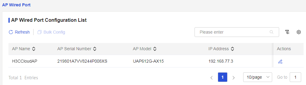
AP wired ports
Procedure
Page Wizard: [Network Management/Network Configuration/AP Wired Port]
|
Set the VLAN for the AP wired port. Select the edit VLAN |
|
|
Enter the VLAN ID, click the < OK > button to complete the configuration. |
|
Parameters
The meanings of the parameters on the page are shown in the table below.
Table 18 Parameter description
|
Parameter |
Description |
|
VLAN ID |
VLAN ID of the faceplate AP wired network port |
|
Refresh |
Update AP List |
|
Bulk Configure |
Select multiple APs to set VLAN ID in bulk |
Loop prevention
Procedure
Page Wizard: [Network Management/Network Configuration/Loop Prevention]
|
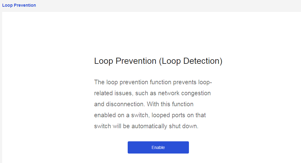
The loop function can effectively prevent issues such as network congestion or loss of connectivity. After enabling this function, if a loop occurs in the network, the loop ports on the connected switch will be automatically closed. |
|
|
Click<to enable>the button and enter the loop prevention configuration. |
|
Parameters
The meanings of the parameters on the page are shown in the table below.
Table 19 Parameter description
|
Parameter |
Description |
|
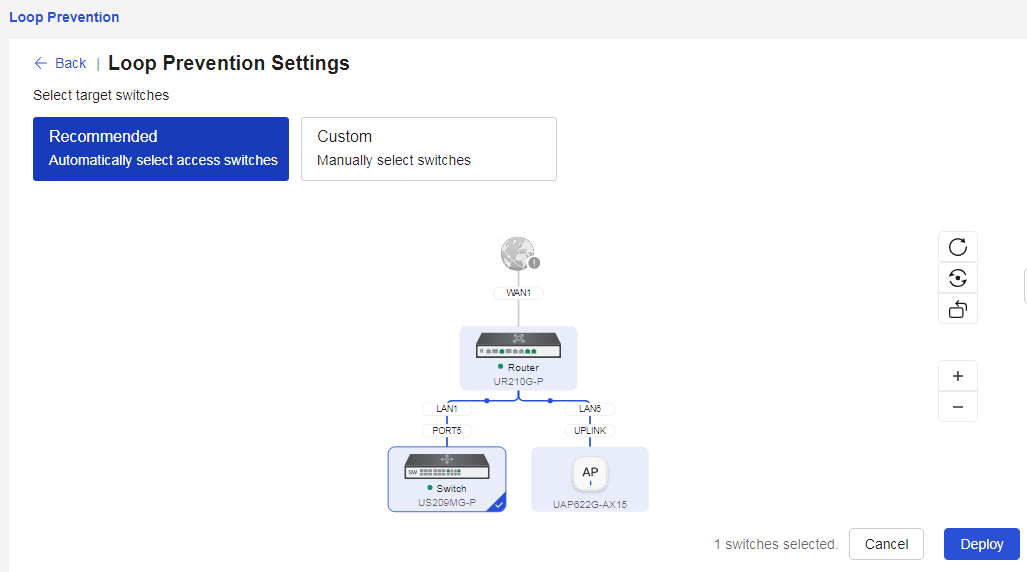
Automatic Identification of Access Switch |
Automatically identify access switches that require enabling the loop prevention function |
|
Manually Select Switch |
In the topology diagram, manually select the switches that need to enable the loop prevention function |
|
Refresh |
Update Topology Data in the Network |
|
Restore |
Restore the arrangement of the network topology structure to the system default state, which arranges the topology structure from top to bottom |
|
Flip |
Arrange the network topology structure from left to right |
|
Cancel Configuration |
Cancel Current Configuration |
|
Deploy Configuration |
Apply Current Configuration |
Private Connection Prevention
Procedure
Page Wizard: [Network Management/Network Configuration/Private Connection Prevention]
|
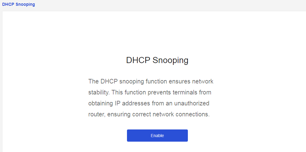
The anti-tampering function can ensure network stability. After enabling this function, it prevents terminal equipment from obtaining incorrect addresses assigned by unauthorized routers, thereby ensuring that the equipment can connect to the network normally. |
|
|
Click < to enable > the button to enter the anti-tampering configuration. |
|

Parameters
The meanings of the parameters on the page are shown in the table below.
Table 20 Parameter description
|
Parameter |
Description |
|
Automatically select all switches |
Automatically select all switches that need to enable the anti-tampering function |
|
Manually select switches |
In the topology diagram, manually select the switches that need to enable the anti-tampering function |
|
Refresh |
Update topology data in the network |
|
Restore |
Restore the arrangement of the topology structure in the network to the system default state, which arranges the topology structure from top to bottom |
|
Flip |
Arrange the topology structure in the network from left to right |
|
Cancel Configuration |
Cancel the current configuration |
|
Deploy Configuration |
Deploy the current configuration |
IPTV
Procedure
Page Wizard: [Network Management/Network Configuration/IPTV]
|
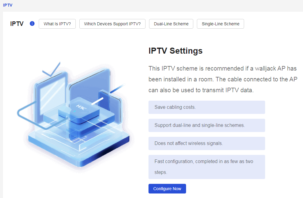
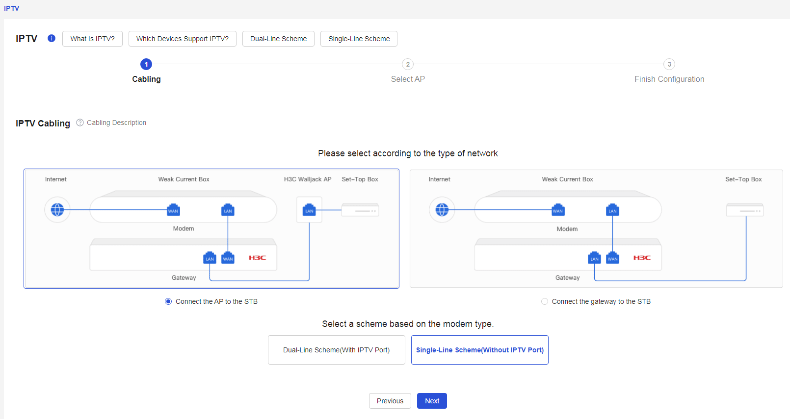
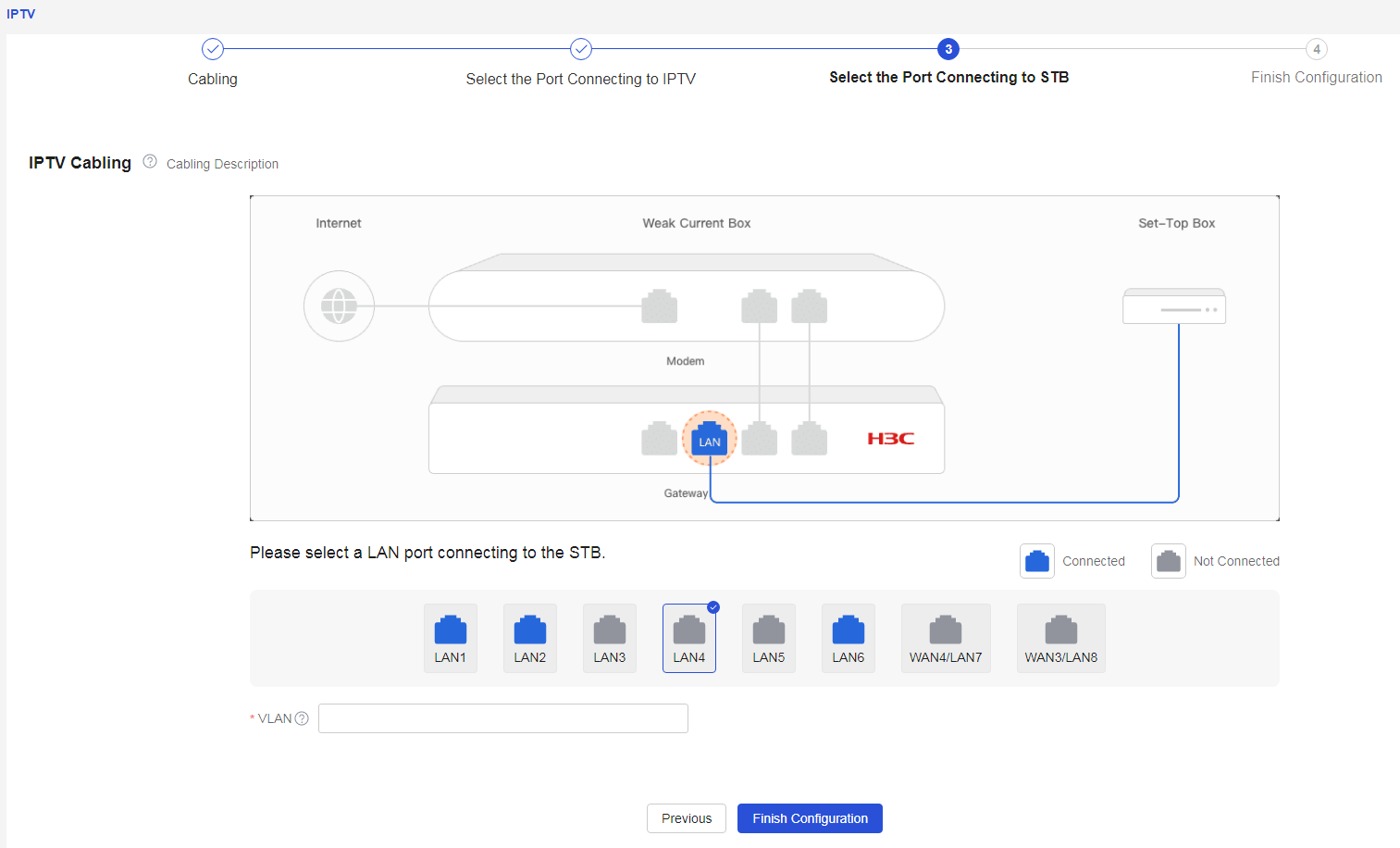
IPTV, or Interactive Internet Protocol Television, is a digital media service that utilizes broadband cable television networks, integrating various technologies such as the Internet, multimedia, and communications to provide users with television data programs. |
|
|
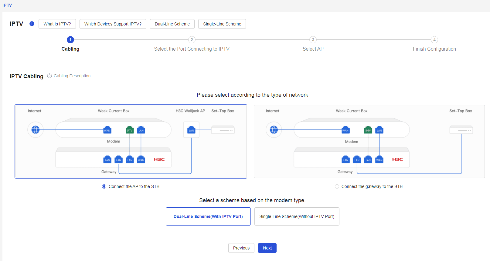
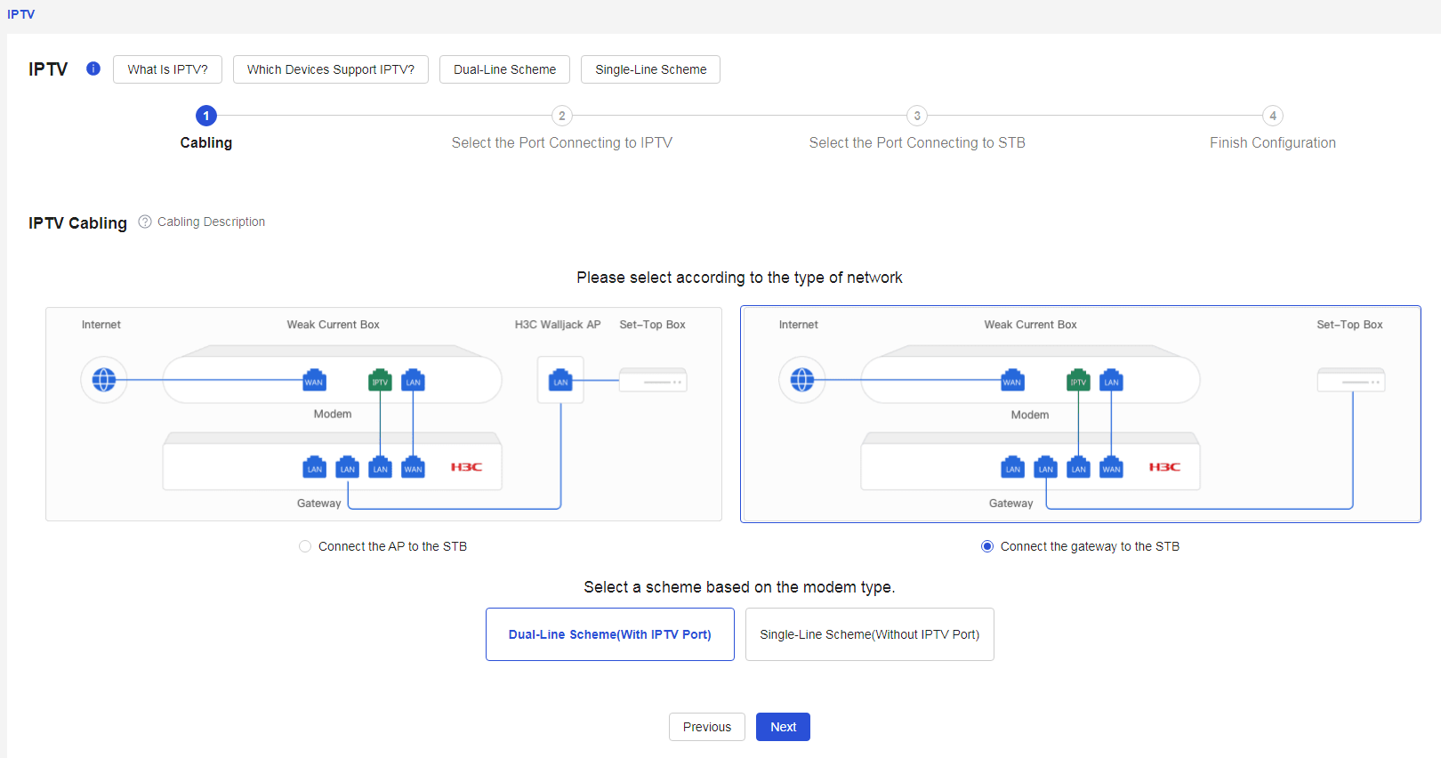
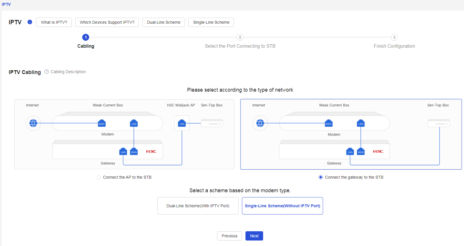
On the IPTV page, click < the Start Configuration > button to begin configuring the IPTV service. · Please select based on the network type. ¡ AP connects to the set-top box (STB). ¡ Gateway connects to the set-top box (STB). · Select a scheme based on the modem type. ¡ Dual-line scheme (with IPTV port). ¡ Single-line scheme (without IPTV port). |
|
|
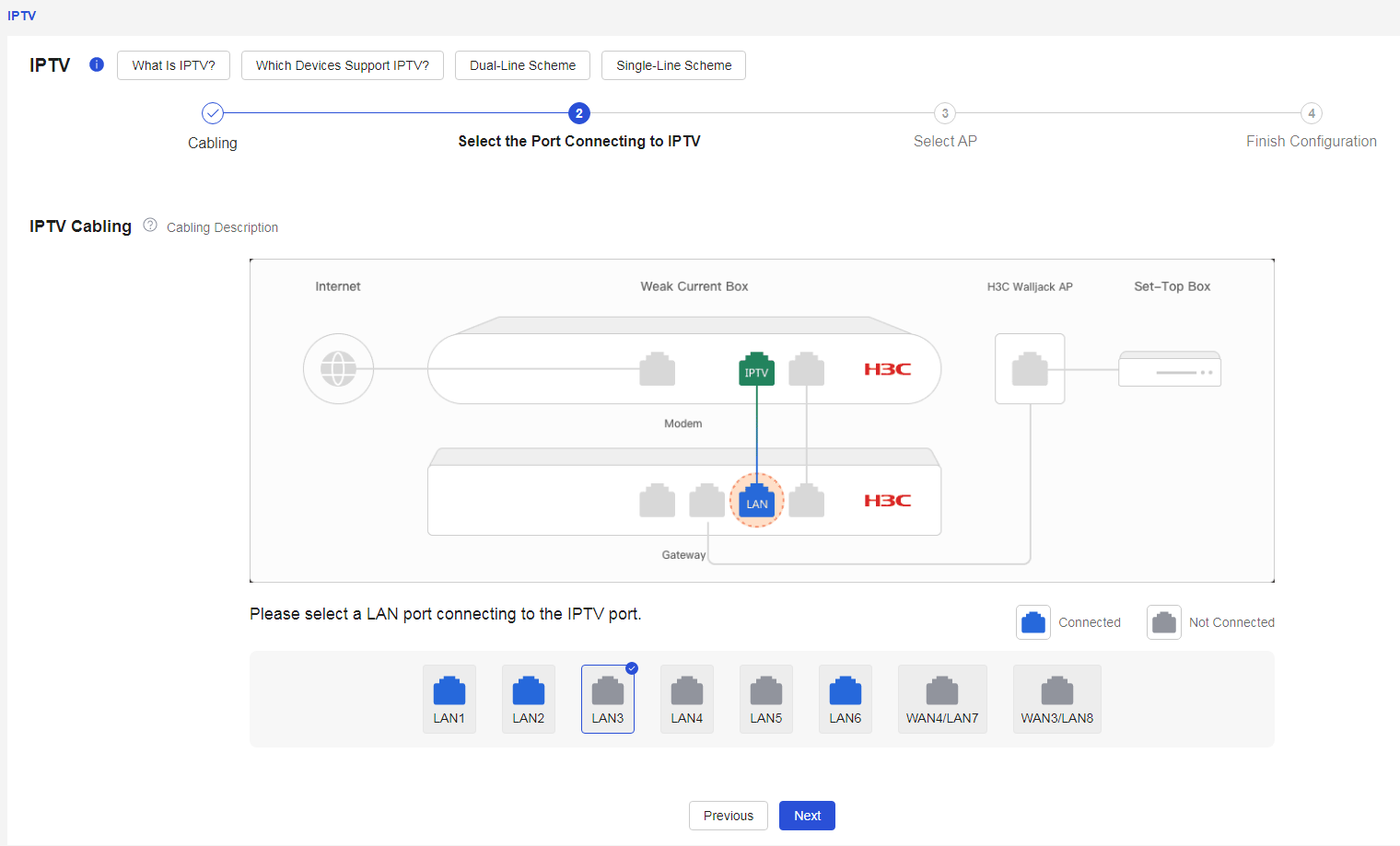
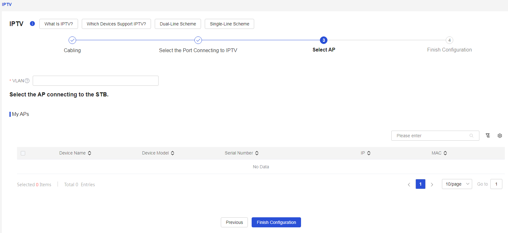
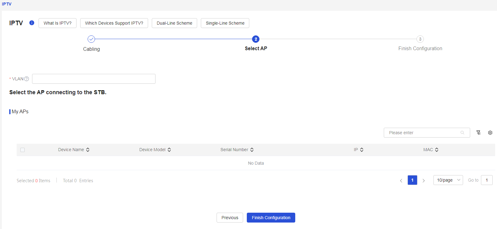
1. If the network type is AP connecting to the set-top box (STB), select the dual-line scheme (with IPTV port) for the optical modem, click < to complete the wiring, and then click the Next > button. 2. Select the LAN port that connects to IPTV. 3. In the VLAN configuration item, enter the IPTV carrier to provide the VLAN ID, and select the AP connected to the set-top box (STB). 4. Click < to complete the configuration > button to finish the setup. |
|
|
1. If the network type is AP connecting to the set-top box (STB), select the single-line scheme (without IPTV port) for the optical modem, click < to complete the wiring, and then click the Next > button. 2. In the VLAN configuration item, enter the IPTV carrier to provide the VLAN ID, and select the AP connected to the set-top box (STB). 3. Click < to complete the configuration > button to finish the setup. |
|
|
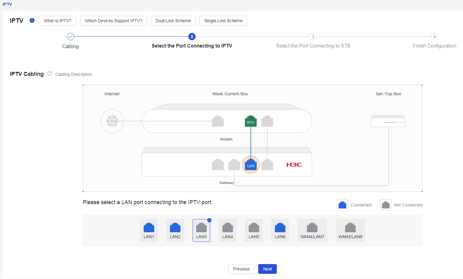
1. If the network type is gateway connecting to the set-top box (STB), select the dual-line scheme (with IPTV port) for the optical modem, click < to complete the wiring, and then click the Next > button. 2. Select the LAN port that connects to IPTV. 3. Please select the LAN port that connects to the set-top box (STB). 4. Click < to complete the configuration > button to finish the setup. |
|
|
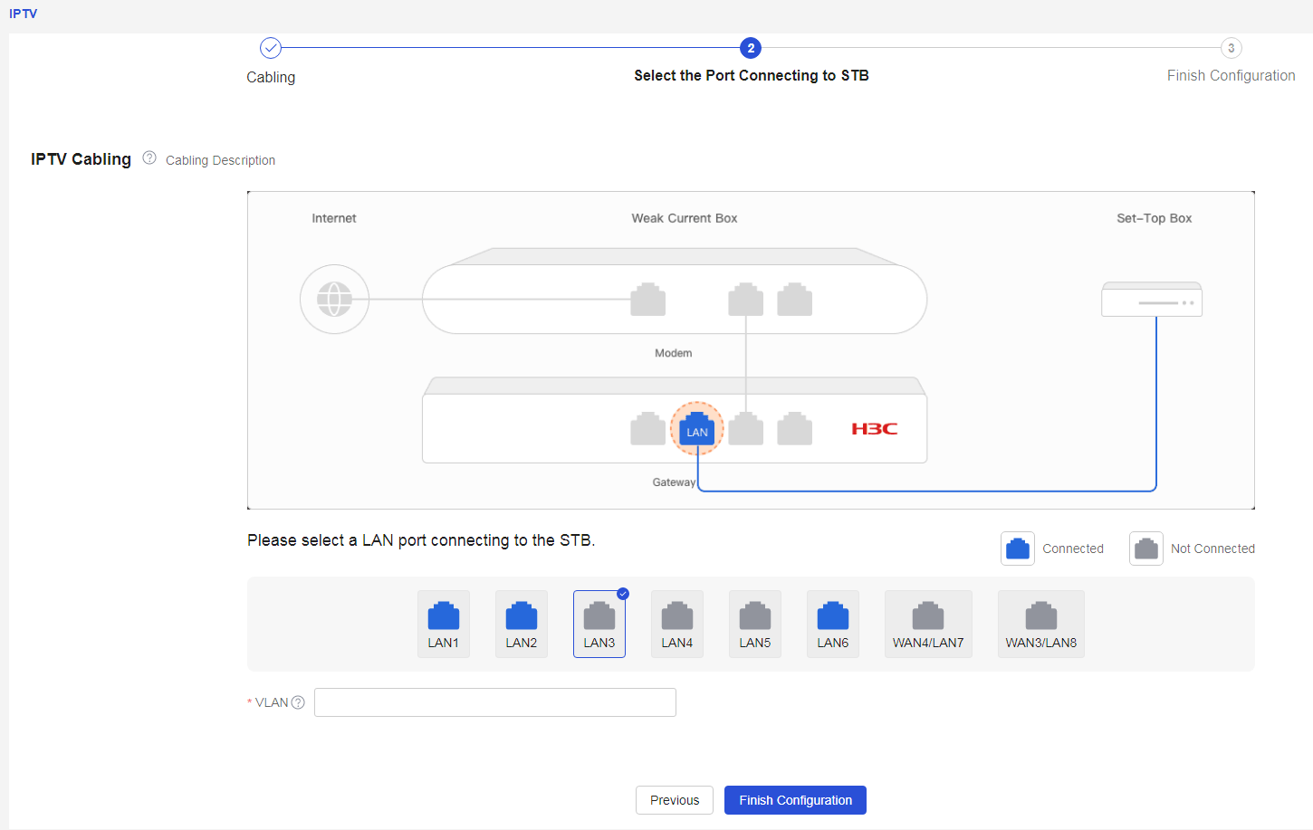
1. If the network type is gateway connecting to the set-top box (STB), select the single-line scheme (without IPTV port) for the optical modem. 2. Select the LAN port that connects to the set-top box (STB). 3. Click < to complete the configuration > button to finish the setup. |
|

Parameters
The meanings of the parameters on the page are shown in the table below.
Table 21 Parameter description
|
Parameter |
Description |
|
Start Configuration |
Begin Configuring IPTV Service |
|
AP Connects to Set-Top Box |
This scenario applies to the connection between the AP and the set-top box. |
|
Gateway Connects to Set-Top Box |
This scenario applies to the connection between the gateway device and the set-top box. |
|
Dual-Line Scheme (with IPTV Port) |
This scheme is suitable for situations where the carrier provides an optical modem with a separate IPTV port, meaning there are two network ports connecting IPTV and network services, requiring two network cables to independently carry the two services. |
|
Single-Line Scheme (without IPTV Port) |
This scheme is suitable for situations where the carrier provides an optical modem without a separate IPTV port. It allows one WAN port of the gateway device to connect to the optical modem, enabling a single network cable to carry both IPTV and network services simultaneously. |
|
VLAN |
IPTV Carrier Provides VLAN ID |
Automatic management
Procedure
Page Wizard: [Network Management/Network Configuration/Automatic Management]
|
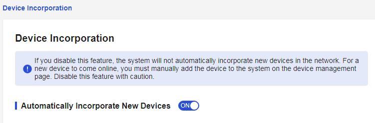
When a new device is connected to the network, the system automatically manages the new device. |
|
Parameters
The meanings of the parameters on the page are shown in the table below.
Table 22 Parameter description
|
Parameter |
Description |
|
Automatically Acknowledge New Devices |
· If you enable the automatic acknowledgment of new devices function, the system will automatically acknowledge new devices in the network. · After disabling the automatic acknowledgment of new devices function, when a new device connects to the network, it will not be automatically acknowledged by the system. You will need to confirm its addition on the device management page for it to come online normally. |
Device management
Device management
Procedure
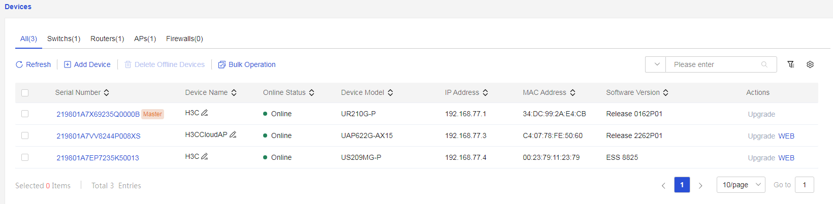
Page Wizard: [Network Management/Device Management]
|
Allows viewing the management information of all devices in the entire network and enables configuration of all devices from a network-wide perspective. |
|
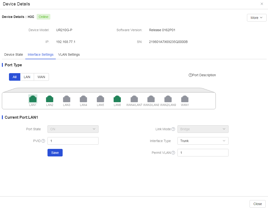
|
Click the corresponding serial number to enter the "Device Details" page, then click "Interface Configuration" to view or modify the interface configuration. 1. In the "Port Type" section, select a port from the device faceplate diagram, and in the "Current Port" section, you can view or modify the current interface configuration: ¡ Select a WAN port from the device faceplate diagram; this example uses the WAN1 port to illustrate how to view or modify the WAN1 port configuration, including settings such as "Connection Type," "IP Address," "DNS Server," "MTU," "Subnet Mask," and "Gateway." ¡ Select a LAN port from the device faceplate diagram; this example uses the LAN1 port to illustrate how to view or modify the LAN1 port configuration, including settings such as "PVID," "Interface Type," and "Permit VLAN." 2. If you modify the port configuration, after confirming it is correct, click the <Save> button to save the port configuration. |
· View or modify the WAN1 port configuration.
· View or modify the LAN1 port configuration.
|
|
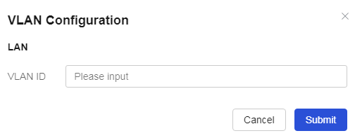
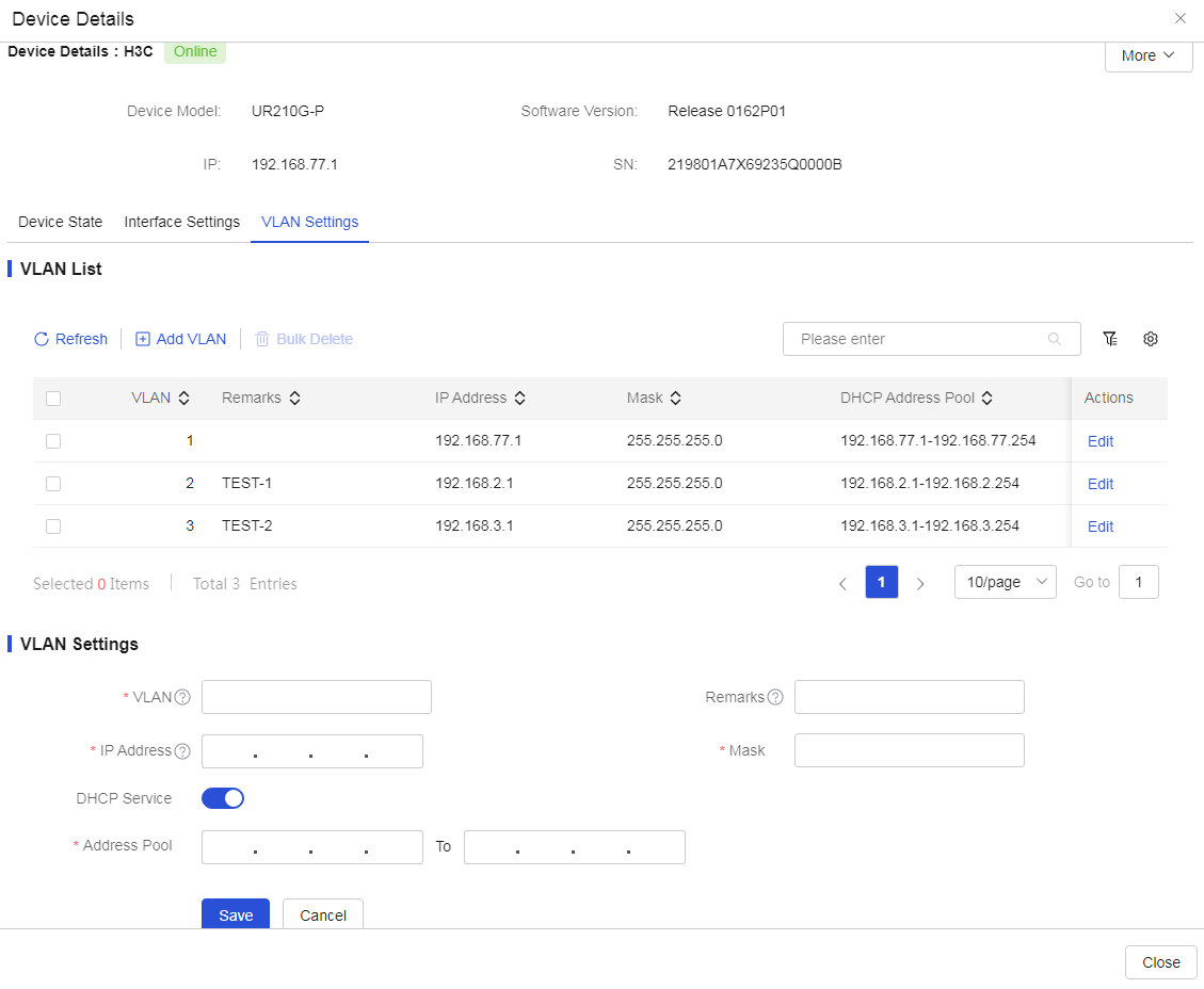
On the "Device Details" page, click "VLAN Configuration" to refresh, create, edit, or delete VLAN configurations. |
|

Parameters
The meanings of the parameters on the page are shown in the table below.
Table 23 Parameter description
|
Parameter |
Description |
|
All |
Manage all devices in the current network. |
|
Switch |
Manage all switches in the current network. |
|
Routes |
Manage all routers in the current network. |
|
AP |
Manage all APs in the current network. |
|
AC |
Manage all ACs in the current network. |
|
Firewall |
Manage all firewalls in the current network. |
|
Refresh |
Refresh device status. |
|
Adding devices |
Add devices to the network. During the addition process, please do not refresh the page or close the browser. If the device is not in factory configuration state, it will revert to factory settings after the addition is complete. |
|
Delete offline devices. |
Remove offline devices from the network. |
|
Batch Operations |
Select the corresponding device checkboxes, click the <Batch Operation> button to perform batch operations on the devices, including "Restart," "Upgrade," "Reset," etc. The master device does not support the "Reset" operation for now. |
|
Serial number |
Display the device's serial number. Click the device's serial number to enter the "Device Details" page. |
|
Device name |
Display the device's name. |
|
Online status |
Display the device's online status. |
|
Switch model |
Display the device's model. |
|
IP |
Display the device's IP address. |
|
MAC |
Display the device's MAC address. |
|
Software version |
Display the device's software version number. |
|
Upgrade |
Upgrade the device. If the upgrade option is grayed out, it indicates that the H3C cloud platform currently does not provide a newer version than the current device version, and therefore online upgrade cannot be executed. |
|
WEB |
Click the <WEB> button for the corresponding device to enter the device's web management interface. |
|
Advanced Search |
Use the <> advanced search function to filter device information in the network by "Contains," "Exact Match," and "Does Not Contain" criteria based on the device's serial number, name, online status, model, IP, MAC, and software version. |
|
Column Sorting. |
Use the <> function to display network device information based on different combinations of serial number, device name, online status, device model, IP, MAC, and software version. |
|
Device Details |
Display device detail information. |
|
SN |
Display the device's SN number. |
|
Deployment Status |
View information such as "Device Status Diagram," "Port Information," "VLAN Division," etc. |
|
Configure the interface settings |
Configure interfaces on the device. |
|
Networking Mode |
Set the WAN interface connection method, including PPPoE, Static IP, DHCP: · PPPoE is a protocol for establishing point-to-point connections over Ethernet, commonly used for authentication and dial-up connections in broadband access environments. When using PPPoE to connect to a wide area network, the user needs to provide specific account and password information, and the router will dial the connection for the user, allowing access to the Internet. · Static IP refers to manually configured static IP addresses, subnet masks, gateway, and DNS server network parameters. These configurations do not change with the device's connection status. · DHCP is a network connection method that dynamically allocates IP addresses. When a device connects to the network, it sends a request to the DHCP server, which dynamically assigns IP addresses, subnet masks, gateways, and DNS servers, enabling the device to quickly connect to the network and obtain necessary IP configuration information. |
|
MTU |
The size of the MTU (Maximum Transmission Unit) that the device interface allows, with a range depending on the type of interface, measured in bytes. |
|
IP address |
The IP address for the device's access to the wide area network. |
|
Subnet mask |
The mask or mask length of the IP address. |
|
DNS servers |
The DNS server address for the device's access to the wide area network. |
|
Gateway |
The gateway address for the device's access to the wide area network. |
|
Bring Up |
Enable or disable this port. |
|
Operating mode |
Switch working modes. The availability of this function depends on the interface; please refer to the actual situation. |
|
PVID |
The default VLAN for this port. |
|
Interface type |
Includes Access ports and Trunk ports. |
|
Permit VLAN |
Allow specified VLANs to pass through the current port. |
|
Configure VLAN settings |
Configure VLANs. |
|
VLAN ID |
The ID number of this VLAN interface. |
|
Create |
Create a new VLAN configuration. |
|
Edit |
Edit VLAN configuration and change settings. |
|
IP address |
Enter the IP address of the interface. |
|
Remarks |
Enter VLAN remark information. |
|
Subnet mask |
Enter the mask or mask length of the IP address, for example, 255.255.255.0 or 24. |
|
DHCP |
Select whether to enable or disable DHCP service based on actual circumstances. |
|
IP pool |
The range of IP addresses allocated by the DHCP server address pool, including starting and ending IP addresses. |
|
Reboot |
Restart the device. |
|
Reset |
Reset the device. |
|
Upgrade |
Upgrade the device. |
|
OFF |
Close the "Device Details" interface. |
Endpoint management
Online users
Procedure
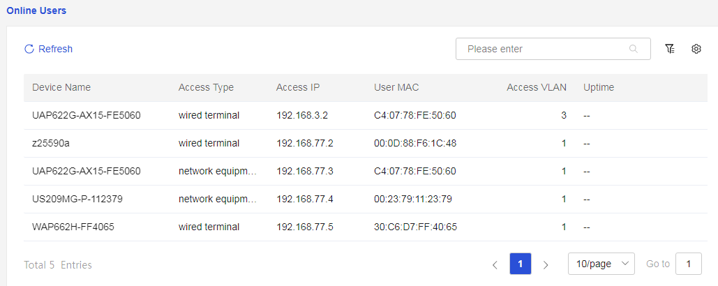
Page Wizard: [Network Management/Terminal Management/Online Users]
|
Display online user information |
|
Parameters
The meanings of the parameters on the page are shown in the table below.
Table 24 Parameter description
|
Parameter |
Description |
|
Refresh |
Refresh online user information |
|
Device name |
View the device names of online users |
|
Access Type |
View the access types of online users |
|
Access IP |
View the access IPs of online users |
|
User MAC |
View the MAC addresses of online users |
|
Access VLAN |
View the access VLANs of online users |
|
Online Duration |
View the online duration of online users |
|
Advanced Search |
Use the advanced search function to filter online user information by "contains," "exact match," and "does not contain" criteria based on device name, access type, access IP, user MAC, access VLAN, and online duration |
|
Sort Order |
Use the function to display online user information based on different combinations of device name, access type, access IP, user MAC, access VLAN, and online duration |
Wireless users
Procedure
Page Wizard: [Network Management/Terminal Management/Wireless Users]
|
Display wireless user information |
|
|
By following the steps below, you can add wireless users to the denylist: · Select the "Add to denylist" function for the corresponding wireless user, ensure it is correct, and click the <Confirm> button to add a single wireless user to the denylist. In this section, users can enter notes for the denylist. · Check the check box in front of the corresponding wireless users, select the "Bulk add to denylist" function, ensure it is correct, and click the <Confirm> button to add multiple wireless users to the denylist. In this section, users can enter notes for the denylist. |
|
|
By following the steps below, you can add wireless users to the whitelist: · Select the "Add to whitelist" function for the corresponding wireless user, ensure it is correct, and click the <Confirm> button to add a single wireless user to the whitelist. In this section, users can enter notes for the whitelist. · Check the check box in front of the corresponding wireless users, select the "Bulk add to whitelist" function, ensure it is correct, and click the <Confirm> button to add multiple wireless users to the whitelist. In this section, users can enter notes for the whitelist. |
|
Parameters
The meanings of the parameters on this page are shown in the table below.
Table 25 Parameter description
|
Parameter |
Description |
|
Refresh |
Refresh wireless user information |
|
MAC |
View wireless user's MAC address |
|
AP |
View wireless user's access AP |
|
IP address |
View wireless user's IP address |
|
Wi-Fi Name |
View wireless user's Wi-Fi name |
|
Wireless Mode |
View wireless user's wireless mode |
|
Online Duration |
View wireless user's online duration |
|
Task |
Add wireless users to denylist or allowlist · Denylist: Add a single wireless user to the denylist, only prohibiting access to the external network for the source MAC address within the denylist; others are allowed access · Allowlist: Add a single wireless user to the allowlist, only allowing access to the external network for the source MAC address within the allowlist; others are prohibited access |
|
Bulk Add to Denylist |
Batch add multiple wireless users to the denylist |
|
Bulk Add to Allowlist |
Batch add multiple wireless users to the allowlist |
|
Sort order |
Use function to display wireless user information based on different combinations of access AP, IP address, Wi-Fi name, wireless mode, and online duration |
System management
System time
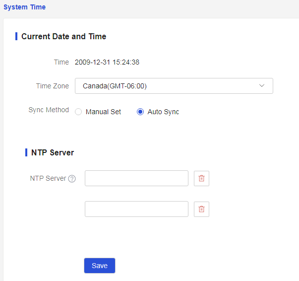
This function allows you to set the system time. The system time includes the date, time, and time zone. To facilitate device management and ensure that this device collaborates with other network devices, you need to configure the device with an accurate system time.
You can use the following methods to obtain the system time:
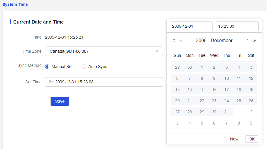
· Manually set the date and time. In this mode, the date and time specified by the user will be the current system time. Subsequently, the device will use its internal clock signal for timing. If the device restarts, the system time will revert to the factory time.
· Automatically synchronize the network date and time. In this mode, the device uses the time obtained from the NTP server as the current system time and periodically synchronizes the time with the NTP server to maintain consistency with the NTP server's system time. Even if this device restarts, it will quickly resynchronize with the NTP server's system time. If there is an NTP server in your managed network, it is recommended to use this mode, as the time obtained is more accurate than manually configured time.
· Obtain the time zone of the device. Configure the time zone of the device as the time zone of the geographical area where the device is located. For example, if the device is in China, select Beijing, Chongqing, Hong Kong SAR, Urumqi (GMT+08:00). If the device is in the United States, select Central Time (US & Canada) (GMT-06:00).
Procedure
Page Wizard: [Network Management/Systems Management/System Time]
|
Set System Time |
|
|
In the “Sync Method” configuration item, select “Manual Setting” to manually set the date and time. 1. In the “Set Time” configuration item, set the current time for the device's geographical area: ¡ Select the date, including “year, month, day”. ¡ Select the time, including “hour, minute, second”. ¡ Select “Now” to automatically set the current time. 2. After confirming everything is correct, click the <Save> button to complete the manual setting of the date and time. |
|
Parameters
The meanings of the parameters on this page are shown in the table below.
Table 26 Parameter description
|
Parameter |
Description |
|
Time |
Current System Date and Time |
|
Time Zone |
Time Zone of the Device's Geographic Area |
|
Manual Settings |
Manually set the date and time. If the device restarts, the system time will recover to the factory time. |
|
Set Time |
Select the date and time, including “year, month, day, hour, minute, second.” |
|
Auto Sync |
Automatically synchronize the network date and time. The time zone configured on the device and the NTP server must be the same; otherwise, it will result in a discrepancy between the device's system time and the NTP server's system time. |
Version management
Upgrading devices
Procedure
Page Wizard: [Network Management/Systems Management/Version Upgrade/Upgrade Device]
|
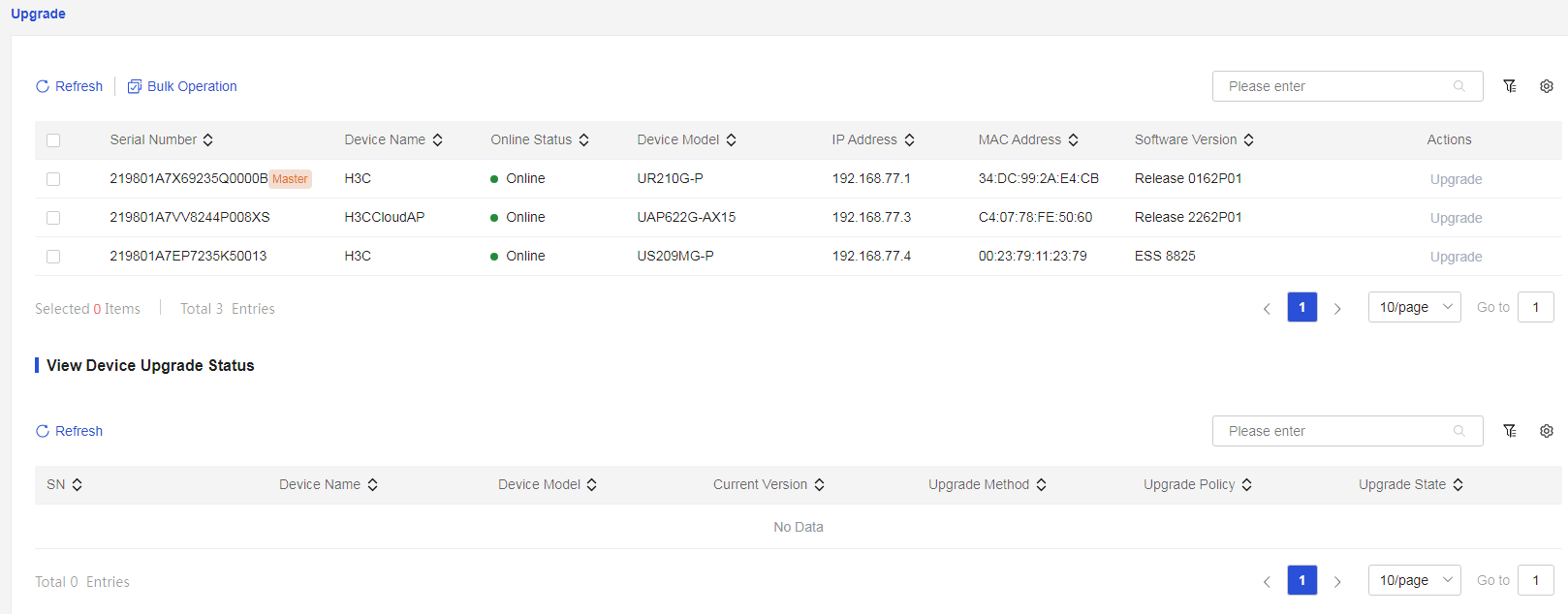
The H3C cloud platform performs online upgrades of the system software on devices. You can achieve this through the following operations: · Select the “upgrade” function for the corresponding device to enter the “device upgrade” page, where you can upgrade a single device. · Sequentially select the check boxes for the corresponding devices, select the “upgrade” function in “batch operations,” and enter the “device upgrade” page to upgrade multiple devices. |
|

Parameters
The meanings of the parameters on this page are shown in the table below.
Table 27 Parameter description
|
Parameter |
Description |
|
Refresh |
Refresh information for devices awaiting upgrade |
|
Batch Operations |
Perform batch upgrades on multiple devices |
|
Upgrade |
Click the "Upgrade" action corresponding to the specified device to upgrade a single device. If the upgrade option is grayed out, it indicates that the H3C cloud platform currently does not provide a version newer than the current device version, thus online upgrade cannot be executed. |
|
Advanced Search |
Use the <> advanced search function with "Include," "Exact Match," and "Exclude" criteria to filter information for devices awaiting upgrade based on serial number, device name, online status, device model, IP, MAC, and software version. |
|
Column Sorting |
Use the <> function to display information for devices awaiting upgrade based on different combinations of serial number, device name, online status, device model, IP, MAC, and software version. |
Viewing device upgrade status
Procedure
Page Wizard: [Network Management/Systems Management/Version Upgrade/View Device Upgrade Status]
|
Upgrade the device and check the device upgrade status |
|
Parameters
The meanings of the parameters on this page are shown in the table below.
Table 28 Parameter description
|
Parameter |
Description |
|
Refresh |
Refresh Device Upgrade Status |
|
Serial number |
View Device Serial Number |
|
Device name |
View Device Name |
|
Switch model |
View Device Model |
|
Current version |
View Device Current Version |
|
Upgrade method |
View Device Upgrade Method |
|
Upgrade Policy |
View Device Upgrade Policy |
|
Upgrade Status |
View Device Upgrade Status |
|
Advanced Search |
Use the advanced search function to filter upgrade information for devices based on conditions such as "contains," "exact match," and "does not contain," according to serial number, device name, device model, current version, upgrade method, upgrade policy, and upgrade status. |
|
Column Sorting |
Use the function to display device upgrade information based on different combinations of serial number, device name, device model, current version, upgrade method, upgrade policy, or upgrade status. |
Configuration management
Backup and Import
Procedure
Page Wizard: [Network Management/Systems Management/Configuration Management/Backup and Import]
|
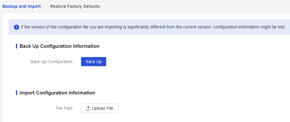
· To export the current configuration file as a backup, click the <Backup> button in the "Backup Configuration Information" section to save the current configuration file. · If the device configuration is incorrect and you want to restore it to the correct operational state, click the <Upload File> button in the "Import Configuration Information" section and select the backup configuration file from the specified path on your local PC to recover the device configuration. |
|
Parameters
The meanings of the parameters on this page are shown in the table below.
Table 29 Parameter description
|
Parameter |
Description |
|
Data backup |
Export the current configuration file as a backup configuration file |
|
Please upload the file |
Import the configuration file from the specified path to the current configuration. Please note: · When importing profile, you must select a file with the .rar extension · If the version of the configuration file you are importing differs significantly from the existing version, it may result in loss of profile · The imported profile will be set as the startup configuration for the next boot and will take effect after the device is restarted |
Restoring factory defaults
Restriction and guidelines
· After restoring to factory defaults, the current settings will be lost. If you do not want to lose the current configuration information, please perform a backup operation first. After restoring factory settings, the device will restart. During this time, do not disconnect the power supply of the device.
· Restoring the factory configuration for a single device will immediately execute the reset; restoring the factory configuration for multiple devices will execute the reset within 30 seconds to 1 minute for the selected devices.
Procedure
Page Wizard: [Network Management/Systems Management/Configuration Management/Restore Factory Configuration]
|
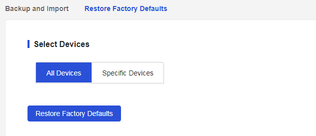
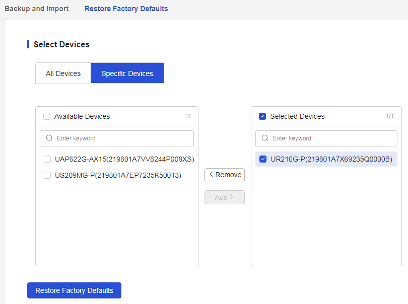
Restore factory configuration for the entire network device or specified device |
|
|
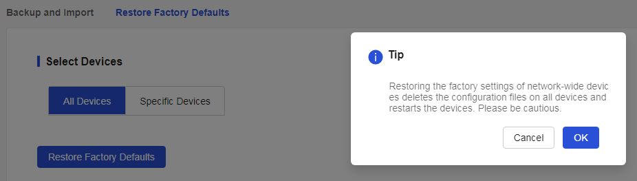
Restore factory configuration for the entire network device: 1. In the “select device” configuration item, select “entire network device,” then click the “restore factory configuration” 2. After confirming the correctness, click the <acknowledge> button to restore the factory defaults for the entire network device |
|
|
Restore factory configuration for a specified device: 1. In the “select device” configuration item, select “specified device” 2. In the “operable devices” list, select the device to be restored to factory configuration and use the <add> button to move the device to the “selected devices” list 3. After confirming the correctness, click the <acknowledge> button to restore the factory defaults for the devices in the “selected devices” list |
|
Parameters
The meanings of the parameters on this page are shown in the table below.
Table 30 Parameter description
|
Parameter |
Description |
|
Whole Network Device |
Performing a factory reset operation on the whole network device will delete all configuration files on the device and restart it. Please proceed with caution. |
|
Select Device |
Performing a factory reset operation on the specified device will delete the configuration files on that device and restart it. Please proceed with caution. |
|
Restore the factory defaults |
Factory reset for the whole network device or specified device |
Management password
Restriction and guidelines
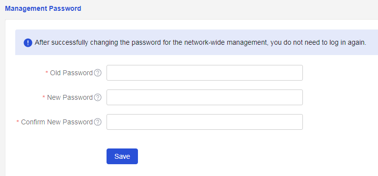
· The password length is 10 to 63 characters and can only contain digits, letters, or English symbols (excluding "space", "?", "'", """", and "\" characters).
· The password must include at least two types of combinations and cannot contain the sequence or reverse sequence of "admin".
· After successfully modifying the device password, you do not need to log in again.
Procedure
Page Wizard: [Network Management/Systems Management/Management Password]
|
Change device management password |
|
Parameters
The meanings of the parameters on this page are shown in the table below.
Table 31 Parameter description
|
Parameter |
Description |
|
Original Management Password |
Current Original Management Password |
|
New Management Password |
Enter the new management password. The password length must be between 10 and 63 characters and can only include digits, letters, or English symbols (excluding "space", "?", "'", "\""). The password must contain at least two types of combinations and cannot include the sequence or reverse sequence of "admin". |
|
Confirm Password |
Re-enter the new management password and ensure it matches the previously entered new management password. |
|
Save |
Complete the management password modification. |
Device restart
Device restart
Restriction and guidelines
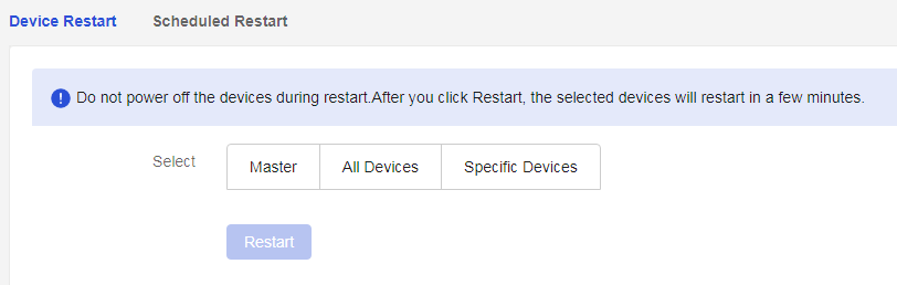
· During the system restart process, do not power off the device.
· A device reboot might result in service interruption. Perform this task with caution.
· When restarting a single device, the device will immediately execute the restart operation; when restarting multiple devices, the selected devices will execute the restart operation within 30 seconds to 1 minute.
Procedure
Page Wizard: [Network Management/Systems Management/Device Restart/Device Restart]
|
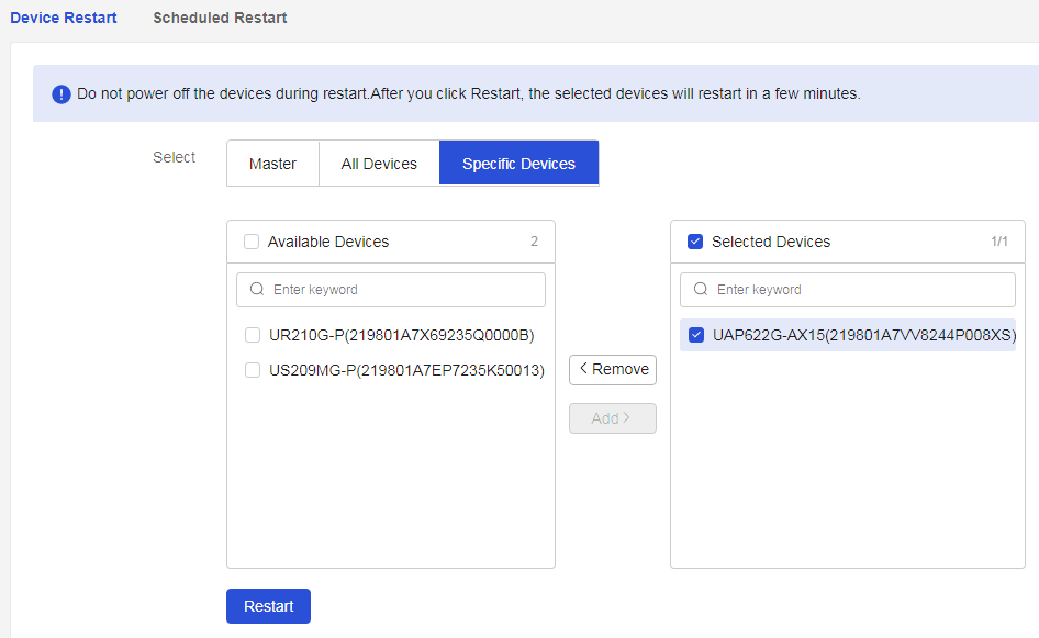
Restart the master device, network devices, or specified devices |
|
|
To restart a specified device: 1. On the "Device Restart" page, select "Specified Device" 2. Select the check box for the device to be restarted, click <Add> button to move the devices from the "Operable Devices" list to the "Selected Devices" list 3. After confirming everything is correct, click <Restart System> button to restart the specified devices in the "Selected Devices" list |
|
Parameters
The meanings of the parameters on this page are shown in the table below.
Table 32 Parameter description
|
Parameter |
Description |
|
Primary Device |
Restart the master device |
|
Whole network devices |
Restart the whole network devices |
|
Select Device |
Restart the specified device |
|
Restart System |
Restart the master device, whole network devices, or specified device |
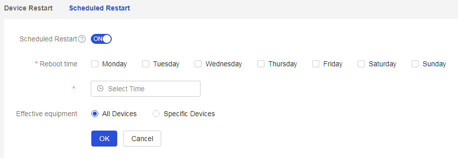
Scheduled restart
Restriction and guidelines
· Enabling this function will perform a timed restart at the specified time. It is recommended to set the timed restart during the early morning or when the network is not in use.
· Before enabling the timed restart function, please ensure that the system time is set to auto synchronization, as this function relies on successful synchronization with NTP.
Procedure
Page Wizard: [Network Management/Systems Management/Device Restart/Timed Restart]
|
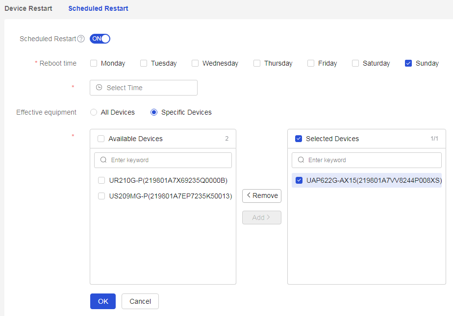
Set scheduled reboot for the entire network device or specified device |
|
|
For specified devices, set scheduled reboot: 1. On the "Scheduled Reboot" page, select "Specified Device" 2. Select the check box for the devices to be scheduled for reboot, click <Add> button to move devices from the "Operable Devices" list to the "Selected Devices" list 3. After confirming that everything is correct, click <Acknowledge> button to complete the setup |
|
Parameters
The meanings of the parameters on this page are shown in the table below.
Table 33 Parameter description
|
Parameter |
Description |
|
Primary Device |
Restart the master device |
|
Whole network devices |
Restart the whole network devices |
|
Select Device |
Restart the specified device |
|
Restart System |
Restart the master device, whole network devices, or specified device |
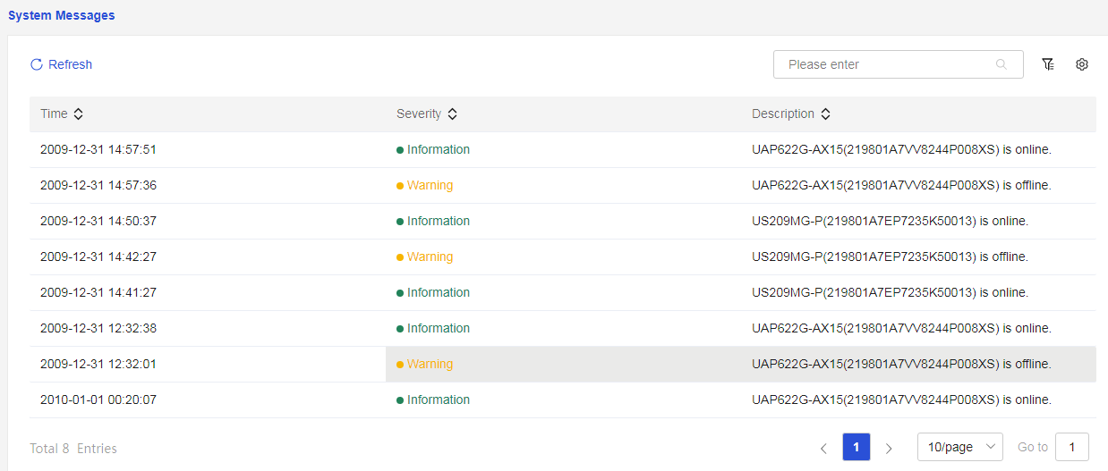
System messages
Procedure
Page Wizard: [Network Management/Systems Management/System Messages]
|
Check system messages |
|
Parameters
The meanings of the parameters on this page are shown in the table below.
Table 34 Parameter description
|
Parameter |
Description |
|
Refresh |
Refresh system messages. |
|
Advanced search |
Use the advanced search |
|
Column sorting |
Use the column sorting |
