- Table of Contents
-
- 04-Layer 3—IP Services Configuration Guide
- 00-Preface
- 01-ARP configuration
- 02-IP addressing configuration
- 03-DHCP configuration
- 04-DNS configuration
- 05-NAT configuration
- 06-IP forwarding basics configuration
- 07-Fast forwarding configuration
- 08-IRDP configuration
- 09-IP performance optimization configuration
- 10-UDP helper configuration
- 11-IPv6 basics configuration
- 12-DHCPv6 configuration
- 13-IPv6 fast forwarding configuration
- 14-HTTP redirect configuration
- Related Documents
-
| Title | Size | Download |
|---|---|---|
| 05-NAT configuration | 279.48 KB |
Contents
Restrictions and guidelines: NAT configuration
Configuring outbound one-to-one static NAT
Configuring outbound net-to-net static NAT
Configuring inbound one-to-one static NAT
Configuring inbound net-to-net static NAT
Configuring outbound dynamic NAT
Configuring inbound dynamic NAT
Configuring dynamic port block mapping for NAT444
Configuring NAT session logging
Configuring NAT444 user logging
Configuring NAT444 alarm logging
Display and maintenance commands for NAT
NAT overview
Network Address Translation (NAT) translates an IP address in the IP packet header to another IP address. Typically, NAT is configured on gateways to enable private hosts to access external networks and external hosts to access private network resources.
Basic NAT concepts
The following describes basic NAT concepts:
· NAT device—A device configured with NAT. Typically, NAT is configured on the edge device that connects the internal and external networks.
· NAT interface—An interface configured with NAT.
· NAT address—A public IP address used for address translation, and this address is reachable from the external network. The NAT address can be manually assigned or dynamically obtained.
· NAT entry—Stores the mapping between a private IP address and a public IP address. For more information, see "NAT entries."
· Easy IP—Uses the IP address of an interface as the NAT address. The IP address of the interface can be manually assigned or be obtained through DHCP or PPPoE.
Basic NAT operating mechanism
Figure 1 shows the basic NAT operating mechanism.
2. Upon receiving a response from the server, NAT translates the destination public address to the private address, and forwards the packet to the host.
The NAT operation is transparent to the terminals (the host and the server). NAT hides the private network from the external users and shows that the IP address of the internal host is 20.1.1.1.

NAT applications
Traditional NAT
Traditional NAT is configured on the interface that connects to the public network. It translates the source IP addresses of outgoing packets and destination IP addresses of incoming packets.
Twice NAT
Twice NAT translates the destination IP address on the receiving interface, and the source IP address on the sending interface. The receiving and sending interfaces are both NAT interfaces.
Twice NAT allows VPNs with overlapping addresses to access each other.
Bidirectional NAT
NAT translates the source and destination IP addresses of incoming packets on the receiving interface and outgoing packets on the sending interface.
Bidirectional NAT supports active access to external network resources from internal users when the internal and external IP addresses overlap.
NAT hairpin
NAT hairpin allows internal hosts to access each other through NAT. The source and destination IP address of the packets are translated on the interface connected to the internal network.
NAT hairpin includes P2P and C/S modes:
· P2P—Allows internal hosts to access each other through NAT. The internal hosts first register their public addresses to an external server. Then, the hosts communicate with each other by using the registered IP addresses.
· C/S—Allows internal hosts to access internal servers through NAT addresses. The destination IP address of the packet going to the internal server is translated by matching the NAT Server configuration. The source IP address is translated by matching the outbound dynamic or static NAT entries.
NAT control
You can use ACLs to implement NAT control. The match criteria in the ACLs include the source IP address, source port number, destination IP address, destination port number, transport layer protocol, and VPN instance. Only packets permitted by an ACL are processed by NAT.
NAT translation methods
Static NAT
Static NAT creates a fixed mapping between a private address and a public address. It supports connections initiated from internal users to external network and from external users to the internal network. Static NAT applies to regular communications.
Dynamic NAT
Dynamic NAT uses an address pool to translate addresses. It applies to the scenario where a large number of internal users access the external network.
NO-PAT
Not Port Address Translation (NO-PAT) translates a private IP address to an IP public address. The public IP address cannot be used by another internal host until it is released.
NO-PAT supports all IP packets.
PAT
Port Address Translation (PAT) translates multiple private IP addresses to a single public IP address by mapping the private IP address and source port to the public IP address and a unique port. PAT supports TCP and UDP packets, and ICMP request packets.
Figure 2 PAT operation
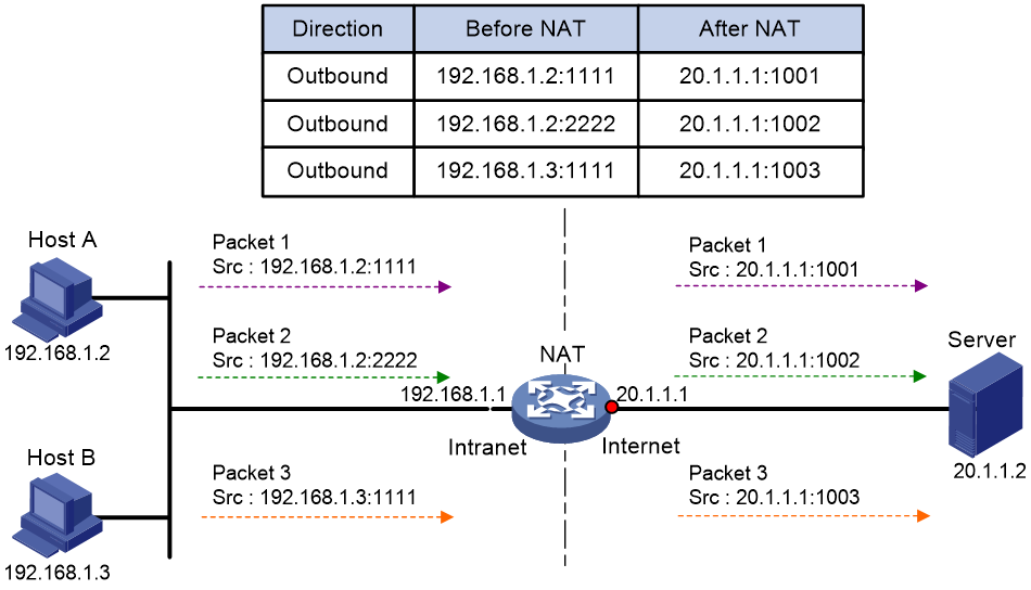
As shown in Figure 2, PAT translates the source IP addresses of the three packets to the same IP public address and translates their port numbers to different port numbers. Upon receiving a response, PAT translates the destination address and port number of the response, and forwards it to the target host.
PAT supports the following mappings:
· Endpoint-Independent Mapping (EIM)—Uses the same IP and port mapping (EIM entry) for packets from the same source IP and port to any destinations. EIM allows external hosts to initiate connections to the translated IP addresses and ports of internal hosts. It allows internal hosts behind different NAT gateways to access each other.
· Address and Port-Dependent Mapping (APDM)—Uses different IP and port mappings for packets from the same source IP and port to different destination IP addresses and ports. APDM allows an external host to initiate connections to an internal host only under the condition that the internal host has previously accessed the external host. It is secure, but it does not allow internal hosts behind different NAT gateways to access each other.
Port block-based NAT
Port block-based NAT is a PAT translation based on port ranges. It maps multiple private IP addresses to one public IP address and uses a different port block for each private IP address. For example, the private IP address 10.1.1.1 of an internal host is mapped to the public IP address 202.1.1.1 and port block 10001 to 10256. When the internal host accesses public hosts, the source IP address 10.1.1.1 is translated to 202.1.1.1, and the source ports are translated to ports in the port block 10001 to 10256.
Dynamic port block mapping
When an internal user initiates a connection to the external network, the dynamic port block-based NAT operates as follows:
1. Uses ACLs to implement translation control. It processes only packets that match an ACL permit rule.
2. Creates a mapping from the internal user's private IP address to a public IP address and a port block.
3. Translates the private IP address to the public IP address, and the source ports to ports in the selected port block for subsequent connections from the private IP address.
4. Withdraws the port block and deletes the dynamic port block mapping when all connections from the private IP address are disconnected.
Dynamic port block mapping supports port block extending. If the ports in the port block for a private address are all occupied, dynamic port block mapping translates the source port to a port in an extended port block.
NAT entries
NAT session entry
NAT creates a NAT session entry for a session and creates an address mapping for the first packet in the session.
A NAT session entry contains extended NAT information, such as interface and translation method. Subsequent packets of the session are translated by using this entry.
· If the direction of the subsequent packets is the same as the direction of the first translated packet, NAT performs the source and destination address translation the same as the first packet.
· If the direction of the subsequent packets is opposite to the direction of the first translated packet, NAT perform reverse address translation. For example, if the source address of the first packet is translated, then the destination address of the subsequent packets is translated.
The session management module maintains the updating and aging of NAT session entries. For information about session management, see Security Configuration Guide.
EIM entry
If EIM is configured on the NAT device, the PAT mode will first create a NAT session entry, and then an EIM entry. The EIM entry is a 3-tuple entry, and it maps a private address/port to a public address/port. The EIM entry ensures:
· Subsequent new connections originating from the same source IP and port uses the same translation as the initial connection.
· Translates the address for new connections initiated from external hosts to the NAT address and port number based on the EIM entry.
An EIM entry ages out after all related NAT session entries age out.
NO-PAT entry
A NO-PAT entry maps a private address to a public address. The same mapping applies to subsequent connections originating from the same source IP.
A NO-PAT entry can also be created during the ALG process for NAT. For information about NAT ALG, see "NAT ALG."
A NO-PAT entry ages out after all related NAT session entries age out.
Port block-based entry
A port block-based entry maps a private IP address to a public IP address and a port block.
For information about these mappings, see "Dynamic port block mapping."
VRF-aware NAT
VRF-aware NAT allows users from different VRF (VPN instances) to access external networks and to access each other.
1. Upon receiving a request from a user in a VRF to an external network, NAT performs the following tasks:
¡ Translates the private source IP address and port number to a public IP address and port number.
¡ Records the VRF information, such as the VRF name.
2. When a response packet arrives, NAT performs the following tasks:
¡ Translates the destination public IP address and port number to the private IP address and port number.
¡ Forwards the packet to the target VRF.
NAT ALG
NAT ALG (Application Level Gateway) translates address or port information in the application layer payloads to ensure connection establishment.
For example, an FTP application includes a data connection and a control connection. The IP address and port number for the data connection depend on the payload information of the control connection. This requires NAT ALG to translate the address and port information for data connection establishment.
Configuring NAT
Restrictions and guidelines: NAT configuration
The general restrictions and guidelines are as follows:
· Configure an ACL to identify the IP addresses to be translated. The match criteria include the source IP address, source port number, destination IP address, destination port number, transport layer protocol, and VPN instance. For more information about ACLs, see ACL and QoS Configuration Guide.
· If NAT is configured on only one output interface in a dual uplink network, do not add the two output interfaces to the same security zone. Doing so will cause communication interruption. For more information about security zone, see Fundamentals Configuration Guide.
· If you perform all the translation methods on an interface, the NAT rules are sorted in the following descending order:
a. Static NAT.
b. Dynamic NAT and NAT444 dynamic port block mapping.
Dynamic NAT and NAT444 dynamic port block mapping have the same priority. Dynamic NAT rules and NAT444 dynamic port block mapping rules are sorted in descending order of ACL numbers and are effective for IPv4 packets.
When you configure BRAS unification, follow these restrictions and guidelines:
· Supported user address types are private IPv4 address, private-DS address, and DS-Lite address.
· If the NAT444 configuration changes after users get online, the public IP addresses and port numbers used by the users also change. The change cannot be synchronized to the AAA server, affecting user tracing accuracy. As a best practice, log off the users immediately after you change the NAT444 configuration. When the users come online again, NAT444 creates new mappings for them.
NAT tasks at a glance
To configure NAT, perform the following tasks:
1. Configuring a translation method on an interface
2. (Optional.) Configuring NAT hairpin
3. (Optional.) Configuring NAT ALG
4. (Optional.) Configuring NAT logging
Configuring static NAT
Restrictions and guidelines
Typically, configure inbound static NAT with outbound dynamic NAT or outbound static NAT to implement bidirectional NAT.
If the device performs forwarding in hardware, apply the QoS policy to the inbound direction of user traffic to ensure that the device can perform address translation.
Prerequisites
Before configuring static NAT, you must perform the following tasks:
· Configure an ACL to identify the IP addresses to be translated. For more information about ACLs, see ACL and QoS Configuration Guide.
· Manually add a route for inbound static NAT. Use local-ip or local-network as the destination address, and use global-ip, an address in global-network, or the next hop directly connected to the output interface as the next hop.
Configuring outbound one-to-one static NAT
About this task
For address translation from a private IP address to a public IP address, configure outbound one-to-one static NAT on the interface connected to the external network.
· When the source IP address of an outgoing packet matches the local-ip, the source IP address is translated into the global-ip.
· When the destination IP address of an incoming packet matches the global-ip, the destination IP address is translated into the local-ip.
Procedure
1. Enter system view.
system-view
2. Configure a one-to-one mapping for outbound static NAT.
nat static outbound local-ip global-ip
3. Enter interface view.
interface interface-type interface-number
4. Enable static NAT on the interface.
nat static enable
By default, static NAT is disabled.
Configuring outbound net-to-net static NAT
About this task
For address translation from a private network to a public network, configure outbound net-to-net static NAT on the interface connected to the external network.
· When the source IP address of an outgoing packet matches the private address range, the source IP address is translated into a public address in the public address range.
· When the destination IP address of an incoming packet matches the public address range, the destination IP address is translated into a private address in the private address range.
Procedure
1. Enter system view.
system-view
2. Configure a net-to-net mapping for outbound static NAT.
nat static outbound net-to-net local-start-address local-end-address [ vpn-instance local-vpn-instance-name ] global global-network { mask-length | mask } [ vpn-instance global-vpn-instance-name ] [ acl { ipv4-acl-number | name ipv4-acl-name } [ reversible ] ]
3. Enter interface view.
interface interface-type interface-number
4. Enable static NAT on the interface.
nat static enable
By default, static NAT is disabled.
Configuring inbound one-to-one static NAT
About this task
For address translation from a public IP address to a private IP address, configure inbound one-to-one static NAT.
· When the source IP address of an incoming packet matches the global-ip, the source IP address is translated into the local-ip.
· When the destination IP address of an outgoing packet matches the local-ip, the destination IP address is translated into the global-ip.
Procedure
1. Enter system view.
system-view
2. Configure a one-to-one mapping for inbound static NAT.
nat static inbound global-ip [ vpn-instance global-vpn-instance-name ] local-ip [ vpn-instance local-vpn-instance-name ] [ acl { ipv4-acl-number | name ipv4-acl-name } [ reversible ] ]
3. Enter interface view.
interface interface-type interface-number
4. Enable static NAT on the interface.
nat static enable
By default, static NAT is disabled.
Configuring inbound net-to-net static NAT
About this task
For address translation from a public network to a private network, configure inbound net-to-net static NAT.
· When the source IP address of an incoming packet matches the public address range, the source IP address is translated into a private address in the private address range.
· When the destination IP address of an outgoing packet matches the private address range, the destination IP address is translated into a public address in the public address range.
Procedure
1. Enter system view.
system-view
2. Configure a net-to-net mapping for inbound static NAT.
nat static inbound net-to-net global-start-address global-end-address [ vpn-instance global-vpn-instance-name ] local local-network { mask-length | mask } [ vpn-instance local-vpn-instance-name ] [ acl { ipv4-acl-number | name ipv4-acl-name } [ reversible ] ]
3. Enter interface view.
interface interface-type interface-number
4. Enable static NAT on the interface.
nat static enable
By default, static NAT is disabled.
Configuring dynamic NAT
Restrictions and guidelines
You can configure multiple inbound or outbound dynamic NAT rules.
· A NAT rule with an ACL takes precedence over a rule without any ACL.
· If two ACL-based dynamic NAT rules are configured, the rule with the higher ACL number has higher priority.
If the device performs forwarding in hardware, apply the QoS policy to the inbound direction of user traffic to ensure that the device can perform address translation.
Prerequisites
Before configuring dynamic NAT, you must perform the following tasks:
· Configure an ACL to identify the IP addresses to be translated. For more information about ACLs, see ACL and QoS Configuration Guide.
· Determine whether to enable the Easy IP feature. If you use the IP address of an interface as the NAT address, you are configuring Easy IP.
· Determine a public IP address pool for address translation.
· Determine whether to translate port numbers. Use NO-PAT to translate only IP addresses and PAT to translate both IP addresses and port numbers.
Configuring outbound dynamic NAT
About this task
To translate private IP addresses into public IP addresses, configure outbound dynamic NAT on the interface connected to the external network.
Procedure
1. Enter system view.
system-view
2. Create a NAT address group and enter its view.
nat address-group group-id
3. Add an address range to the address group.
address start-address end-address
You can add multiple address ranges to an address group.
The address ranges must not overlap.
4. Return to system view.
quit
5. Enter interface view.
interface interface-type interface-number
6. Configure outbound dynamic NAT. Choose the options to configure as needed:
¡ Configure NO-PAT.
nat outbound [ ipv4-acl-number | name ipv4-acl-name ] address-group group-id [ vpn-instance vpn-instance-name ] no-pat [ reversible ]
¡ Configure PAT.
nat outbound [ ipv4-acl-number | name ipv4-acl-name ] [ address-group group-id ] [ vpn-instance vpn-instance-name ] [ port-preserved ]
You can configure multiple outbound dynamic NAT rules on an interface.
|
Parameter |
Description |
|
address-group |
If you do not specify this keyword, the IP address of the interface is used as the NAT address. Easy IP is implemented. |
|
no-pat reversible |
If you specify these keywords, you enable reverse address translation. Reverse address translation uses existing NO-PAT entries to translate the destination address for connections actively initiated from the external network to the internal network. The destination address is translated into the private IP address in the matching NO-PAT entry. |
7. (Optional.) Execute the following commands in sequence to configure a PAT mapping mode.
quit
nat mapping-behavior endpoint-independent [ acl { ipv4-acl-number | name ipv4-acl-name } ]
The default mapping mode is Address and Port-Dependent Mapping.
This command takes effect only on outbound dynamic NAT for PAT.
Configuring inbound dynamic NAT
Restrictions and guidelines
Do not configure inbound dynamic NAT alone. Typically, inbound dynamic NAT functions with outbound dynamic NAT or outbound static NAT to implement bidirectional NAT.
As a best practice, manually create a route because it takes time to automatically add routes.
Procedure
1. Enter system view.
system-view
2. Create a NAT address group and enter its view.
nat address-group group-id
3. Add an address range to the address group.
address start-address end-address
You can add multiple address ranges to an address group.
The address ranges in address groups must not overlap.
4. Return to system view.
quit
5. Enter interface view.
interface interface-type interface-number
6. Configure inbound dynamic NAT.
nat inbound { ipv4-acl-number | name ipv4-acl-name } address-group group-id [ vpn-instance vpn-instance-name ] [ no-pat [ reversible ] [ add-route ] ]
You can configure multiple inbound dynamic NAT rules on an interface.
|
Parameter |
Description |
|
no-pat reversible |
If you specify these keywords, you enable reverse address translation. Reverse address translation uses existing NO-PAT entries to translate the destination address for connections actively initiated from the external network to the internal network. The destination address is translated into the private IP address in the matching NO-PAT entry. |
|
add-route |
This keyword enables the device to automatically add a route destined for the private address when an inbound dynamic NAT rule is matched. The output interface is the NAT interface, and the next hop is the source address before translation. If you do not specify this keyword, you must manually add the route. |
Configuring NAT444
About NAT444
NAT444 provides outbound address translation, and it is configured on the interface connected to the public network. By configuring NAT444 address translation on the NAT444 gateway, multiple private IP addresses are mapped to one public IP address and a different port block is used for each private IP address.
Restrictions and guidelines
To configure dynamic port block mapping for NAT444, you must configure port block parameters in the NAT address group.
Configuring dynamic port block mapping for NAT444
Restrictions and guidelines
If the device performs forwarding in hardware, apply the QoS policy to the inbound direction of user traffic to ensure that the device can perform address translation. In a QoS policy, the traffic class matches the packets to be NATed and the traffic behavior redirects the packets to the CPU.
Procedure
1. Enter system view.
system-view
2. (Optional.) Configure a PAT mapping mode.
nat mapping-behavior endpoint-independent [ acl { ipv4-acl-number | name ipv4-acl-name } ]
The default mapping mode is Address and Port-Dependent Mapping.
3. Create a NAT address group, and enter its view.
nat address-group group-id
4. Add a public IP address range to the NAT address group.
address start-address end-address
You can add multiple public IP address ranges to an address group.
The IP address ranges in address groups cannot overlap.
5. (Optional.) Configure the port range for the public IP addresses.
port-range start-port-number end-port-number
By default, the port range is 1 to 65535.
The configuration takes effect only on PAT translation mode.
6. Configure port block parameters.
port-block block-size block-size [ extended-block-number extended-block-number ]
The configuration takes effect only on PAT translation mode.
7. Return to system view.
quit
8. Enter interface view.
interface interface-type interface-number
9. Configure PAT for outbound dynamic NAT.
nat outbound [ ipv4-acl-number | name ipv4-acl-name ] [ address-group group-id ] [ vpn-instance vpn-instance-name ] [ port-preserved ]
By default, no outbound dynamic NAT rules exist.
The port-preserved keyword does not take effect on dynamic NAT444.
Configuring NAT hairpin
About this task
NAT hairpin allows internal hosts to access each other or allows internal hosts to access internal servers. The source and destination IP addresses of the packets are translated on the interface connected to the internal network.
Restrictions and guidelines
NAT hairpin works in conjunction with outbound dynamic NAT or outbound static NAT.
To configure the P2P mode, you must configure outbound PAT on the interface connected to the external network and enable the EIM mapping mode.
Procedure
1. Enter system view.
system-view
2. Enter interface view.
interface interface-type interface-number
3. Enable NAT hairpin.
nat hairpin enable
By default, NAT hairpin is disabled.
Configuring NAT ALG
1. Enter system view.
system-view
2. Configure NAT ALG for a protocol or all protocols.
nat alg { all | dns | ftp | h323 | icmp-error | ils | mgcp | nbt | pptp | rsh | rtsp | sccp | sip | sqlnet | tftp | xdmcp }
By default, NAT ALG is enabled.
Configuring NAT logging
Configuring NAT session logging
About this task
NAT session logging records NAT session information, including translation information and access information.
A NAT device generates NAT session logs for the following events:
· NAT session establishment.
· NAT session removal. This event occurs when you add a configuration with a higher priority, remove a configuration, change ACLs, when a NAT session ages out, or when you manually delete a NAT session.
· Active NAT session logging. Active NAT flows refer to NAT sessions that exist within a period of time. When the specified interval for logging active NAT flows expires, the device records the existing NAT session information and generates a log.
Procedure
1. Enter system view.
system-view
2. Enable NAT logging.
nat log enable [ acl { ipv4-acl-number | name ipv4-acl-name } ]
By default, NAT logging is disabled.
3. Enable NAT session logging.
¡ For NAT session establishment events:
nat log flow-begin
¡ For NAT session removal events:
nat log flow-end
¡ For active NAT flows:
nat log flow-active minutes
By default, NAT session logging is disabled.
Configuring NAT444 user logging
About this task
NAT444 user logs are used for user tracing. The NAT444 gateway generates a user log whenever it assigns or withdraws a port block. The log includes the private IP address, public IP address, and port block. You can use the public IP address and port numbers to locate the user's private IP address from the user logs.
A NAT444 gateway generates NAT user logs when one of the following events occurs:
· A port block is assigned.
For the NAT444 static port block mapping, the NAT444 gateway generates a user log when it translates the first connection from a private IP address.
For the NAT444 dynamic port block mapping, the NAT444 gateway generates a user log when it assigns or extends a port block for a private IP address.
· A port block is withdrawn.
For the NAT444 static port block mapping, the NAT444 gateway generates a user log when all connections from a private IP address are disconnected.
For the NAT444 dynamic port block mapping, the NAT444 gateway generates a user log when all the following conditions are met:
¡ All connections from a private IP address are disconnected.
¡ The port blocks (including the extended ones) assigned to the private IP address are withdrawn.
¡ The corresponding mapping entry is deleted.
Prerequisites
Before configuring NAT444 user logging, you must configure the custom NAT444 log generation and outputting features. For more information, see Network Management and Monitoring Configuration Guide.
Procedure
1. Enter system view.
system-view
2. Enable NAT logging.
nat log enable [ acl { ipv4-acl-number | name ipv4-acl-name } ]
By default, NAT logging is disabled.
The acl keyword does not take effect on NAT444 user logging.
3. Enable NAT444 user logging. Choose the options to configure as needed:
¡ For port block assignment:
nat log port-block-assign
¡ For port block withdrawal:
nat log port-block-withdraw
By default, NAT444 user logging is disabled.
Configuring NAT444 alarm logging
About this task
If the public IP addresses, port blocks, or ports in selected port blocks (including extended ones) are all occupied, the NAT444 gateway cannot perform address translation and packets will be dropped. To monitor the usage of public IP addresses and port block resources, you can configure NAT444 alarm logging.
A NAT444 gateway generates alarm logs when one of the following occurs:
· In the static port block mapping, the ports in the selected port block are all occupied.
· In the dynamic port block mapping, the ports in the selected port blocks (including extended ones) are all occupied.
· In the dynamic port block mapping, the public IP addresses and port blocks are all assigned.
Prerequisites
Before configuring NAT444 alarm logging, you must configure the custom NAT444 log generation and outputting features. For more information, see Network Management and Monitoring Configuration Guide.
Procedure
1. Enter system view.
system-view
2. Enable NAT logging.
nat log enable [ acl { ipv4-acl-number | name ipv4-acl-name } ]
By default, NAT logging is disabled.
The acl keyword does not take effect on NAT444 alarm logging.
3. Enable NAT444 alarm logging.
nat log alarm
By default, NAT444 alarm logging is disabled.
Display and maintenance commands for NAT
Execute display commands in any view and reset commands in user view.
|
Task |
Command |
|
Display all NAT configuration information. |
display nat all |
|
Display NAT address group information. |
display nat address-group [ group-id ] |
|
Display information about NAT EIM entries. |
display nat eim [ slot slot-number ] |
|
Display information about inbound dynamic NAT. |
display nat inbound |
|
Display NAT logging configuration. |
display nat log |
|
Display information about NAT NO-PAT entries. |
display nat no-pat [ slot slot-number ] |
|
Display information about outbound dynamic NAT. |
display nat outbound |
|
Display NAT sessions. |
display nat session [ { source-ip source-ip | destination-ip destination-ip } * [ vpn-instance vpn -instance-name ] ] [ slot slot-number ] [ verbose ] |
|
Display static NAT mappings. |
display nat static |
|
Display NAT statistics. |
display nat statistics [ summary ] [ slot slot-number ] |
|
Display NAT port block mappings. |
display nat port-block dynamic [ slot slot-number ] |
|
Clear NAT sessions. |
reset nat session [ slot slot-number ] |
NAT configuration examples
Example: Configuring outbound one-to-one static NAT
Network configuration
Configure static NAT to allow the host at 10.110.10.8/24 to access the Internet.
Figure 3 Network diagram

Procedure
# Specify IP addresses for the interfaces on the switch. (Details not shown.)
# Configure a one-to-one static NAT mapping between the private address 10.110.10.8 and the public address 202.38.1.100.
<Switch> system-view
[Switch] nat static outbound 10.110.10.8 202.38.1.100
# Enable static NAT on Vlan-interface 200.
[Switch] interface vlan-interface 200
[Switch-Vlan-interface200] nat static enable
[Switch-Vlan-interface200] quit
# Configure ACL 2000 to identify packets from subnet 10.110.10.0/24 to pass through.
[Switch] acl basic 2000
[Switch-acl-ipv4-basic-2000] rule permit source 10.110.10.0 0.0.0.255
[Switch-acl-ipv4-basic-2000] quit
# Configure traffic class nat to match advanced ACL 2000.
[Switch] traffic classifier nat
[Switch-classifier-nat] if-match acl 2000
[Switch-classifier-nat] quit
# Configure traffic behavior nat to redirect packets matching ACL 2000 to the CPU.
[Switch] traffic behavior nat
[Switch-behavior-nat] redirect cpu
[Switch-behavior-nat] quit
# Configure a QoS policy and associate the traffic class with the traffic behavior.
[Switch] qos policy p1
[Switch-qospolicy-p1] classifier nat behavior nat
[Switch-qospolicy-p1] quit
# Apply the QoS policy to the inbound traffic on GigabitEthernet 1/0/1.
[Switch] interface gigabitethernet 1/0/1
[Switch-GigabitEthernet1/0/1] qos apply policy p1 inbound
[Switch-GigabitEthernet1/0/1] quit
Verifying the configuration
# Verify that the host at 10.110.10.8/24 can access the server on the Internet. (Details not shown.)
# Display static NAT configuration.
[Switch] display nat static
Static NAT mappings:
Totally 1 outbound static NAT mappings.
IP-to-IP:
Local IP : 10.110.10.8
Global IP : 202.38.1.100
Config status: Active
Interfaces enabled with static NAT:
Totally 1 interfaces enabled with static NAT.
Interface: Vlan-interface200
Config status: Active
# Display NAT session information.
[Switch] display nat session verbose
Initiator:
Source IP/port: 10.110.10.8/42496
Destination IP/port: 202.38.1.111/2048
DS-Lite tunnel peer: -
VPN instance/VLAN ID/VLL ID: -/-/-
Protocol: ICMP(1)
Inbound interface: Vlan-interface100
Responder:
Source IP/port: 202.38.1.111/42496
Destination IP/port: 202.38.1.100/0
DS-Lite tunnel peer: -
VPN instance/VLAN ID/VLL ID: -/-/-
Protocol: ICMP(1)
Inbound interface: Vlan-interface200
State: TCP_ESTABLISHED
Application: FTP
Start time: 2022-05-11 10:06:55 TTL: 27s
Initiator->Responder: 5 packets 420 bytes
Responder->Initiator: 5 packets 420 bytes
Total sessions found: 1
Example: Configuring outbound dynamic NAT
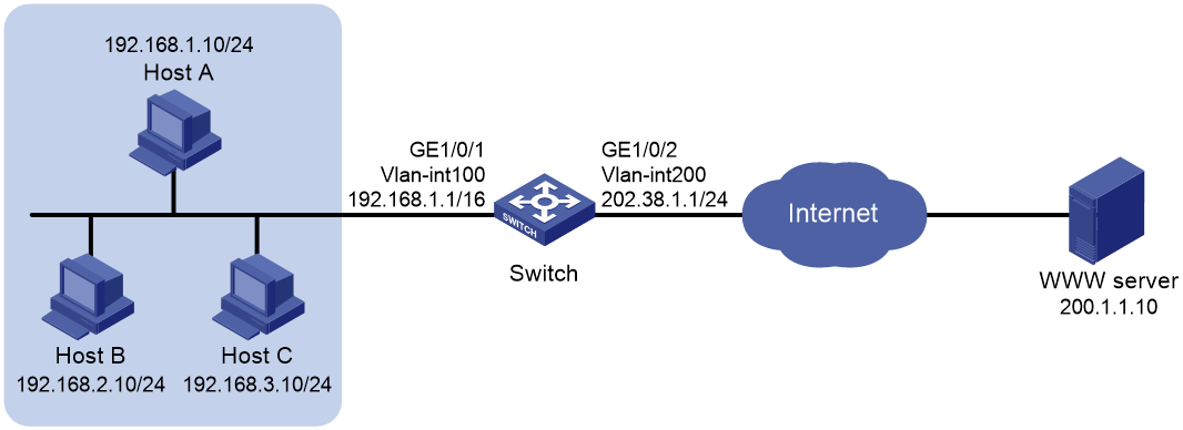
Network configuration
As shown in Figure 4, a company has a private address 192.168.0.0/16 and two public IP addresses 202.38.1.2 and 202.38.1.3. Configure outbound dynamic NAT to allow only internal users on subnet 192.168.1.0/24 to access the Internet.
Procedure
# Specify IP addresses for the interfaces on the switch. (Details not shown.)
# Configure address group 0 and add an address range from 202.38.1.2 to 202.38.1.3.
<Switch> system-view
[Switch] nat address-group 0
[Switch-address-group-0] address 202.38.1.2 202.38.1.3
[Switch-address-group-0] quit
# Configure ACL 2000 to identify packets from subnet 192.168.1.0/24.
[Switch] acl basic 2000
[Switch-acl-ipv4-basic-2000] rule permit source 192.168.1.0 0.0.0.255
[Switch-acl-ipv4-basic-2000] quit
# Enable outbound dynamic PAT on Vlan-interface 200. The source IP addresses of the packets permitted by ACL 2000 are translated into the addresses in address group 0.
[Switch] interface vlan-interface 200
[Switch-Vlan-interface200] nat outbound 2000 address-group 0
[Switch-Vlan-interface200] quit
# Configure traffic class nat to match advanced ACL 2000.
[Switch] traffic classifier nat
[Switch-classifier-nat] if-match acl 2000
[Switch-classifier-nat] quit
# Configure traffic behavior nat to redirect packets matching ACL 2000 to the CPU.
[Switch] traffic behavior nat
[Switch-behavior-nat] redirect cpu
[Switch-behavior-nat] quit
# Configure a QoS policy and associate the traffic class with the traffic behavior.
[Switch] qos policy p1
[Switch-qospolicy-p1] classifier nat behavior nat
[Switch-qospolicy-p1] quit
# Apply the QoS policy to the inbound traffic on GigabitEthernet 1/0/1.
[Switch] interface gigabitethernet 1/0/1
[Switch-GigabitEthernet1/0/1] qos apply policy p1 inbound
[Switch-GigabitEthernet1/0/1] quit
Verifying the configuration
# Verify that Host A can access the WWW server, but Host B and Host C cannot. (Details not shown.)
# Display all NAT configuration information.
[Switch] display nat all
NAT address group information:
Totally 1 NAT address groups.
Address group 0:
Port range: 1-65535
Address information:
Start address End address
202.38.1.2 202.38.1.3
NAT outbound information:
Totallu 1 NAT outbound rules.
Interface: Vlan-interface200
ACL: 2000 Address group: 0 Port-preserved: N
NO-PAT: N Reversible: N
Config status: Active
NAT logging:
Log enable : Disabled
Flow-begin : Disabled
Flow-end : Disabled
Flow-active : Disabled
Port-block-assign : Disabled
Port-block-withdraw : Disabled
Alarm : Disabled
NAT mapping behavior:
Mapping mode : Address and Port-Dependent
ACL : ---
Config status: Active
Static NAT load balancing: Disabled
# Verify that Host A access to the WWW server generates NAT sessions.
[Switch] display nat session verbose
Initiator:
Source IP/port: 192.168.1.10/52992
Destination IP/port: 200.1.1.10/2048
DS-Lite tunnel peer: -
VPN instance/VLAN ID/VLL ID: -/-/-
Protocol: ICMP(1)
Inbound interface: Vlan-interface100
Responder:
Source IP/port: 200.1.1.10/4
Destination IP/port: 202.38.1.3/0
DS-Lite tunnel peer: -
VPN instance/VLAN ID/VLL ID: -/-/-
Protocol: ICMP(1)
Inbound interface: Vlan-interface200
State: ICMP_REPLY
Application: INVALID
Start time: 2022-05-11 10:39:49 TTL: 12s
Initiator->Responder: 1 packets 84 bytes
Responder->Initiator: 1 packets 84 bytes
Total sessions found: 1