- Table of Contents
-
- 21-Network Management and Monitoring Configuration Guide
- 00-Preface
- 01-Ping and tracert configuration
- 02-System debugging configuration
- 03-NQA configuration
- 04-iNQA configuration
- 05-NTP configuration
- 06-SNMP configuration
- 07-RMON configuration
- 08-Event MIB configuration
- 09-CWMP configuration
- 10-Sampler configuration
- 11-Mirroring configuration
- 12-NetStream configuration
- 13-IPv6 NetStream configuration
- 14-Cloud connection configuration
- 15-Packet capture configuration
- 16-sFlow configuration
- 17-IP traffic statistics collection configuration
- Related Documents
-
| Title | Size | Download |
|---|---|---|
| 09-CWMP configuration | 629.78 KB |
Contents
Obtaining the ACS parameters through DHCP
Forcibly renewing the ACS parameters through DHCP
Automatic base station deployment via CWMP
Restrictions and guidelines: CWMP configuration
Specifying a CPE service port number
Configuring the preferred ACS parameters to be deployed by the DHCP server
Configuring the default ACS parameters from the CLI
Specifying an SSL client policy for HTTPS connection to ACS
Configuring ACS authentication
Configuring autoconnect parameters
Configuring the CWMP connection interface
Enabling NAT traversal for the CPE
Configuring the provision code
Verifying and maintaining CWMP
Example: Automatically deploying base stations through IPv4 CWMP on the same subnet as the ACS
Example: Automatically deploying base stations through IPv6 CWMP on the same subnet as the ACS
Example: Automatically deploying base stations through IPv4 CWMP on a different subnet from the ACS
Example: Automatically deploying base stations through IPv6 CWMP on a different subnet from the ACS
Configuring CWMP
About CWMP
CPE WAN Management Protocol (CWMP), also called "TR-069," is a DSL Forum technical specification for remote management of network devices.
The protocol was initially designed to provide remote autoconfiguration through a server for large numbers of dispersed end-user devices in a network. CWMP can be used on different types of networks, including Ethernet.
CWMP network framework
Figure 1 shows a basic CWMP network framework.
Figure 1 CWMP network framework
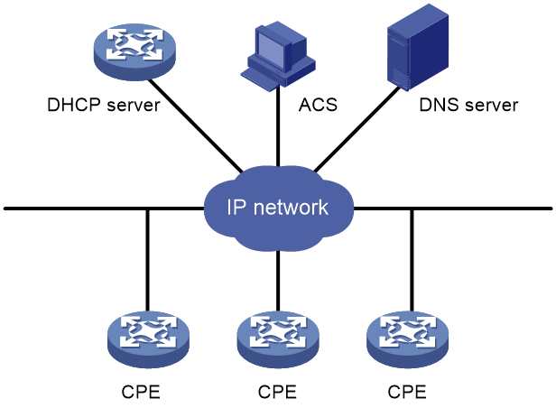
A basic CWMP network includes the following network elements:
· ACS—Autoconfiguration server, the management device in the network.
· CPE—Customer premises equipment, the managed device in the network.
· DNS server—Domain name system server. CWMP defines that the ACS and the CPE use URLs to identify and access each other. DNS is used to resolve the URLs.
· DHCP server—Assigns ACS parameters along with IP addresses to CPEs when the CPEs are powered on. DHCP server is optional in CWMP. With a DHCP server, you do not need to configure ACS parameters manually on each CPE. The CPEs can contact the ACS automatically when they are powered on for the first time.
The device is operating as a CPE in the CWMP framework.
Basic CWMP functions
You can autoconfigure and upgrade CPEs in bulk from the ACS.
Autoconfiguration
You can create configuration files for different categories of CPEs on the ACS. Based on the device models and serial numbers of the CPEs, the ACS verifies the categories of the CPEs and issues the associated configuration to them.
The following are methods available for the ACS to issue configuration to the CPE:
· Transfers the configuration file to the CPE, and specifies the file as the next-startup configuration file. At a reboot, the CPE starts up with the ACS-specified configuration file.
· Runs the configuration in the CPE's RAM. The configuration takes effect immediately on the CPE. For the running configuration to survive a reboot, you must save the configuration on the CPE.
CPE software management
The ACS can manage CPE software upgrade.
When the ACS finds a software version update, the ACS notifies the CPE to download the software image file from a specific location. The location can be the URL of the ACS or an independent file server.
If the CPE successfully downloads the software image file and the file is validated, the CPE notifies the ACS of a successful download. If the CPE fails to download the software image file or the file is invalidated, the CPE notifies the ACS of an unsuccessful download.
After successful download, the CPE restarts immediately to finish the upgrade.
|
|
NOTE: The applicable image file format (.ipe, .tar, or .tar.gz) varies by device model. |
Data backup
The ACS can require the CPE to upload a configuration file or log file to a specific location. The destination location can be the ACS or a file server.
CPE status and performance monitoring
The ACS can monitor the status and performance of CPEs. Table 1 shows the available CPE status and performance objects for the ACS to monitor.
Table 1 CPE status and performance objects available for the ACS to monitor
|
Category |
Objects |
Remarks |
|
Device information |
Manufacturer ManufacturerOUI SerialNumber HardwareVersion SoftwareVersion |
N/A |
|
Operating status and information |
DeviceStatus UpTime |
N/A |
|
Configuration file |
ConfigFile |
Local configuration file stored on CPE for upgrade. The ACS can issue configuration to the CPE by transferring a configuration file to the CPE or running the configuration in CPE's RAM. |
|
CWMP settings |
ACS URL |
URL address of the ACS to which the CPE initiates a CWMP connection. This object is also used for main/backup ACS switchover. |
|
ACS username ACS password |
When the username and password of the ACS are changed, the ACS changes the ACS username and password on the CPE to the new username and password. When a main/backup ACS switchover occurs, the main ACS also changes the ACS username and password to the backup ACS username and password. |
|
|
PeriodicInformEnable |
Whether to enable or disable the periodic Inform feature. |
|
|
PeriodicInformInterval |
Interval for periodic connection from the CPE to the ACS for configuration and software update. |
|
|
PeriodicInformTime |
Scheduled time for connection from the CPE to the ACS for configuration and software update. |
|
|
ConnectionRequestURL (CPE URL) |
N/A |
|
|
ConnectionRequestUsername (CPE username) ConnectionRequestPassword (CPE password) |
CPE username and password for authentication from the ACS to the CPE. |
How CWMP works
CWMP data model
The CWMP feature follows the TR069 protocol that defines TR098 and TR181 data models. Different data models use different node IDs and support different nodes and different data structures for the nodes. However, the differences of data models do not affect how CWMP works. To establish a CWMP connection, the data model used on the device must be the same as that used on the ACS.
RPC methods
CWMP uses remote procedure call (RPC) methods for bidirectional communication between CPE and ACS. The RPC methods are encapsulated in HTTP or HTTPS.
Table 2 shows the primary RPC methods used in CWMP.
|
RPC method |
Description |
|
Get |
The ACS obtains the values of parameters on the CPE. |
|
Set |
The ACS modifies the values of parameters on the CPE. |
|
Inform |
The CPE sends an Inform message to the ACS for the following purposes: · Initiates a connection to the ACS. · Reports configuration changes to the ACS. · Periodically updates CPE settings to the ACS. |
|
Download |
The ACS requires the CPE to download a configuration or software image file from a specific URL for software or configuration update. CWMP supports the following file types: · 1—The firmware upgrade image represents the startup software image of the device. The types of startup software image files saved on the ACS vary by device model, for example, *.ipe, *.tar, and *.tar.gz. · 3—The vendor configuration file represents a .cfg configuration file specific to a vendor. · 103—The base station startup file is a standard XML file that contains device configuration in XML format for base station deployment. Supported transfer protocols are HTTP, HTTPS, and FTP. |
|
Upload |
The ACS requires the CPE to upload a file to a specific URL. |
|
Reboot |
The ACS reboots the CPE remotely for the CPE to complete an upgrade or recover from an error condition. |
CPE autoconnection to ACS
The CPE automatically initiates a connection to the ACS when one of the following events occurs:
· ACS URL change. The CPE initiates a connection request to the new ACS URL.
· CPE startup. The CPE initiates a connection to the ACS after the startup.
· Timeout of the periodic Inform interval. The CPE re-initiates a connection to the ACS at the Inform interval.
· Expiration of the scheduled connection initiation time. The CPE initiates a connection to the ACS at the scheduled time.
CWMP connection establishment
As shown in Figure 2, the procedure of establishing a connection between the CPE and the ACS is as follows:
1. After obtaining the basic ACS parameters, the CPE initiates a TCP connection to the ACS.
2. If HTTPS is used, the CPE and the ACS initialize SSL for a secure HTTP connection.
3. The CPE sends an Inform message in HTTPS to initiate a CWMP session.
4. After the CPE passes authentication, the ACS returns an Inform response to establish the session.
5. After sending all requests, the CPE sends an empty HTTP post message.
Figure 2 CWMP connection establishment

Automatic main/backup ACS switchover
Typically, two ACSs are used in a CWMP network for consecutive monitoring on CPEs. When the main ACS needs to reboot or fails, the CPE must connect to the backup ACS to complete main/backup ACS switchover.
As shown in Figure 3, the procedure of an automatic main/backup ACS switchover is as follows:
1. Before the main ACS reboots, it queries the ACS URL set on the CPE.
2. The CPE replies with its ACS URL setting.
3. The main ACS sends a Set request to change the ACS URL on the CPE to the backup ACS URL.
4. After the ACS URL is modified, the CPE sends a response.
5. The main ACS sends an empty HTTP message to notify the CPE that it has no other requests.
6. The CPE closes the connection to the main ACS.
Then, the CPE initiates a new connection to the backup ACS URL.
Figure 3 Automatic main and backup ACS switchover

Obtaining the ACS parameters through DHCP
Application scenarios
For a device to actively establish a connection as a CPE to the ACS and be incorporated by the ACS, the device must first obtain ACS parameters, including ACS URL, and username and password for logging in to the ACS. The ACS parameters can be configured manually or obtained from a DHCP server through DHCP.
In this mode, a device can obtain both IP address and ACS parameters during the deployment process. Then, the device can automatically connect to the ACS and be incorporated by the ACS.
DHCP sub-option parsing modes
CWMP supports automatic configuration retrieval through sub-options of DHCPv4 option 43 and DHCPv6 option 17. Different users have varying requirements for the sub-options that can be carried in the DHCP option fields based on their service needs. The device supports both the default mode and Telecom mode for parsing the sub-options of the DHCP option to best meet user service requirements.
By default, CWMP uses the default mode to parse DHCP option fields. Table 3 shows the differences between the default mode and Telecom mode.
Table 3 DHCP sub-option parsing modes
|
DHCP-suboption parsing mode |
Requirements |
Application scenarios |
|
Default mode |
You can deploy only the ACS configuration and must deploy the following simultaneously: · URL of the ACS · Username used by the device to access ACS · Password used by the device to access ACS |
To use this method for automatic network deployment, make sure the CPE and the ACS are located in the same subnet. |
|
Telecom mode |
You can deploy not only the ACS configuration but also other settings such as VLAN, gateway addresses, and static routes. For more information, see Table 4. |
To use this method for automatic network deployment, the CPE and ACS can be on different subnets, and the CPE can communicate with the ACS through the default route or static routes provided. |
Table 4 DHCP sub-options that can be parsed by CWMP in Telecom mode
|
DHCP sub-option code |
DHCP suboption name |
Description |
|
1 |
SN |
Device unique identifier This field is required in Telecom networking standards. |
|
2 |
OUI |
Vendor Organizationally Unique Identifier (OUI). This field is required in Telecom networking standards. |
|
4 |
· OM IP address subnet mask (DHCPv4) · OM IP address Prefix Length (DHCPv6) |
IP address mask or IPv6 address prefix length of the CPE. · In a DHCPv4 environment, this field is the IPv4 address mask of the CPE. · In a DHCPv6 environment, this field is the IPv6 address prefix length of the CPE. This field is required in Telecom networking standards. |
|
5 |
OM Gateway address |
IPv4/IPv6 gateway address of the CPE. This field is required in Telecom networking standards. |
|
6 |
OM VlanID |
Created VLAN ID on the CPE. This field is required in Telecom networking standards. |
|
7 |
Management Server URL |
ACS URL to which the CPE will connect. This field is required in Telecom networking standards. |
|
8 |
Username |
Username used by the CPE to access the ACS. This field is required in Telecom networking standards. |
|
9 |
Password |
Password used by the CPE to access the ACS. This field is required in Telecom networking standards. |
|
10 |
Routing Target IP address |
IPv4/IPv6 destination address of the static route deployed to the CPE. This field is required in Telecom networking standards. |
|
11 |
OM Next hop IP address |
Next hop IPv4/IPv6 address of the static route deployed to the CPE. This field is required in Telecom networking standards. |
|
12 |
· Routing net mask (DHCPv4) · Routing Prefix Length (DHCPv6) |
· In a DHCPv4 environment, this field is the address mask of the base station. · In a DHCPv6 environment, this field is the prefix length of the base station. This field is required in Telecom networking standards. |
Operation mechanism
The process of automatically deploying configurations to a CPE through the DHCP server is as follows:
1. Use the sub-options of DHCPv4 option 43 (for IPv4) or DHCPv6 option 17 (for IPv6) to deploy configurations to the CPE:
2. With CWMP enabled, the system registers with the DHCP module of the CPE, which in turn notifies the CWMP module of the current value of the DHCP sub-option.
DHCP sub-option updates are performed as follows:
¡ If CWMP is enabled but ACS parameters are not configured, or if the CPE fails to connect to the ACS, the CPE will actively initiate a DHCP renewal upon the reaching of the trigger threshold for forced updates. Through lease renewal, the CPE obtains the values of the DHCP sub-options and makes them effective. This method is suitable for ACS initial deployment or scenarios where switching to a backup ACS is required due to the failure of the original ACS.
¡ As a DHCP client, the device obtains new DHCP sub-options from the DHCP server through IP address requests or periodic IP lease renewals, and then communicates the current DHCP sub-options to the CWMP module. The CWMP module acquires the values of these DHCP sub-options and activates them. This method is suitable for automatically updating parameters shown in Table 4 during the device operation.
3. CWMP uses the parameters deployed by the sub-options to establish connections with ACS.
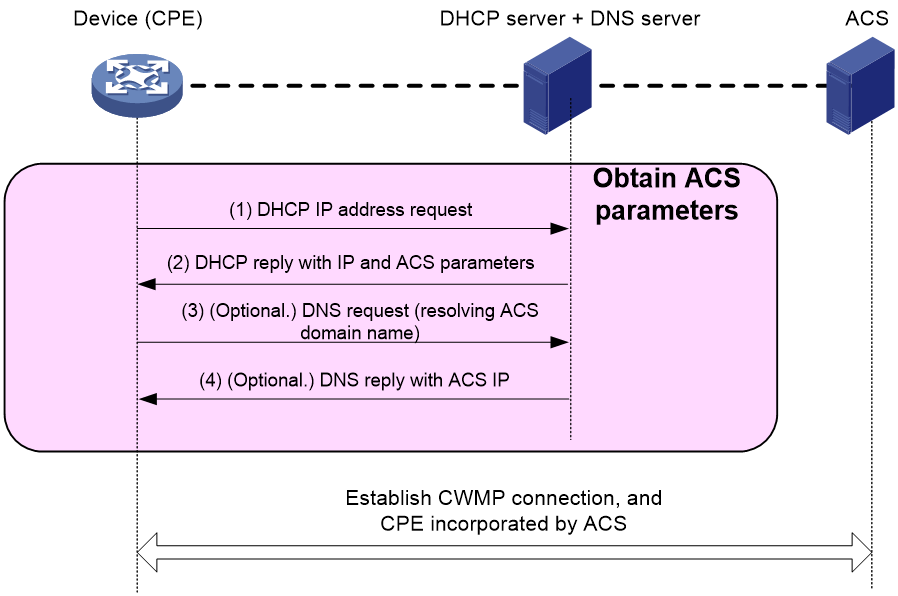
Figure 4 shows the process for the device to obtain IP addresses and ACS parameters through DHCP in deployment.
Figure 4 Obtaining IP addresses and ACS parameters through DHCP in deployment
|
|
NOTE: The CPE supports obtaining ACS parameters through DHCPv6 option 17 or DHCPv4 option 43 from the DHCP server. If the DHCP server assigns ACS parameters through DHCPv6 option 17, the CPE will use the ACS parameters assigned through option 17 rather than other fields to establish a connection to the ACS. Follow these restrictions and guideline: · For IPv6, configure the option 17 parameter on the DHCP server. · For IPv4, configure the option 43 parameter rather than the option 17 parameter. For more information about DHCP and option fields, see DHCP configuration in Layer 3—IP Services Configuration Guide. |
Forcibly renewing the ACS parameters through DHCP
Application scenarios
Use this feature to forcibly trigger DHCP renewal when ACS parameters are assigned through a DHCP server. DHCP renewal can renew the ACS parameters, including ACS URL, username, and password.
Operating mechanism
By default, after an interface is configured to obtain an IP address through DHCP, it will obtain an IP address from the DHCP server. The IP address has a certain lease duration. After the lease duration expires, the DHCP server will reclaim the IP address. Therefore, a DHCP client will renew its IP address lease from the DHCP server when about half of the lease duration elapses. At this time, if the administrator modifies ACS parameters on the DHCP server, the DHCP server will include the new ACS parameters in the lease renewal response message. The CPE obtains new ACS parameters and uses them to establish a CWMP connection.
In summary, the CPE triggers a lease renewal when about half of the lease duration (12 hours by default) elapses to update ACS parameters. For faster lease renewal and re-obtaining ACS parameters, forcibly renew ACS parameters through DHCP. If the ACS fails, it can switch to the standby ACS more quickly.
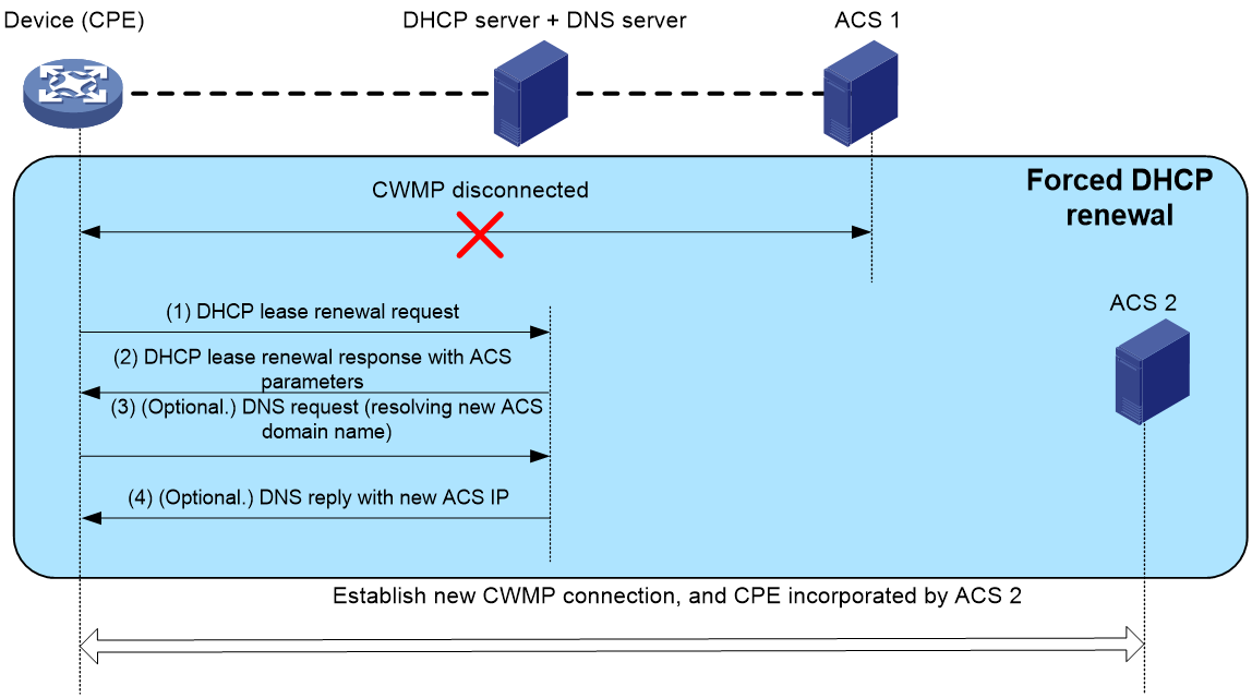
A CWMP-enabled device will automatically enable the feature of forcibly renewing ACS parameters through DHCP. A device will initiate the DHCP IP address renewal process to obtain ACS parameters again in either of the following conditions:
· The device is not configured with an ACS URL.
If the device is not configured with an ACS URL, CWMP will immediately initiate a DHCP IP address renewal process to retrieve ACS parameters.
· CWMP connection establishment fails, and the number of consecutive failures reaches the threshold set by using the cwmp cpe dhcp force-renew threshold command.
For example, if the username and password for ACS authentication are modified, the device cannot establish a CWMP connection to the ACS. Or, if the current ACS is faulty and cannot establish CWMP connections, you must replace it with a new ACS to continue incorporating the device. In this case, CWMP will wait for the device to establish a connection to the ACS. If CWMP connection establishment fails, and the number of consecutive failures reaches the threshold set by using the cwmp cpe dhcp force-renew threshold command, CWMP will consider the current ACS to be faulty. Then, CWMP will trigger the device to initiate a DHCP renewal process to retrieve ACS parameters from the DHCP server again.
Whether the IP address of the interface changes after renewal depends on the DHCP renewal configuration.
Figure 5 Flowchart for forced ACS parameter renewal through DHCP
Automatic base station deployment via CWMP
|
|
CAUTION: The automatic base station deployment via CWMP feature requires a configuration file in standard XML format. This feature will fail if a file in any other format is used. |
The automatic base station deployment via CWMP feature enables zero-touch provisioning for devices through CWMP. Typically, this feature is used in carrier networks to automatically deploy new base stations and provide Internet access services for mobile users in the communities.
The administrator stores the prepared CPE deployment file (base station startup file) on a file server. A CPE obtains the file URL from the ACS and retrieves the base station startup file according to the URL. Then, the CPE initiates the automatic deployment process and complete the deployment. The administrator can configure devices without going to the installation site. For the devices to access the network, onsite personnel only need to install, connect, and power on the devices, achieving zero-touch provisioning.
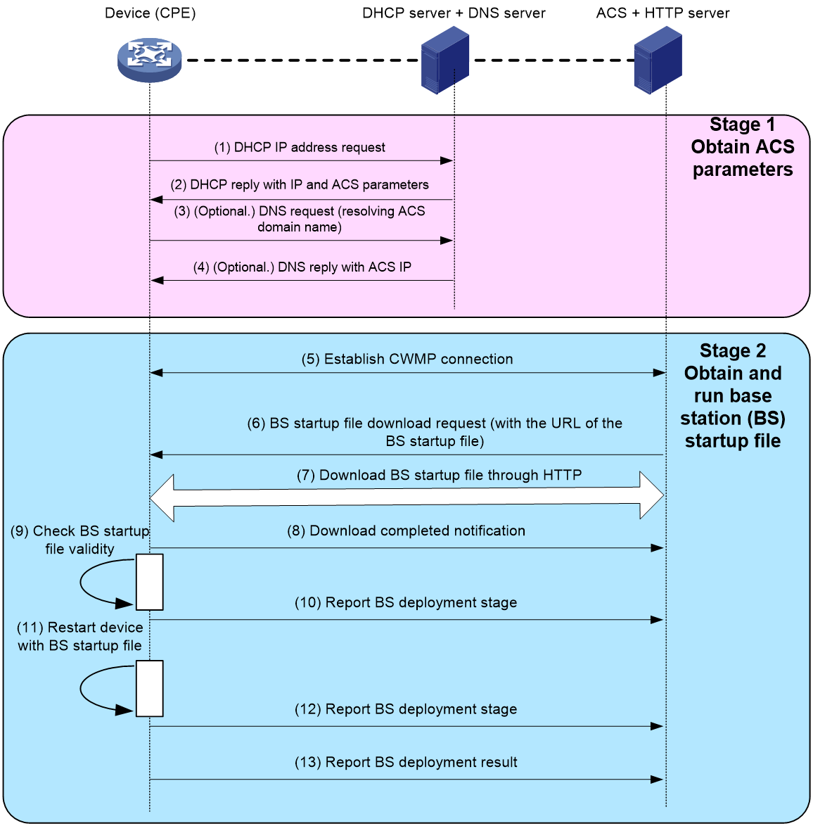
As shown in Figure 6, the process of automatic base station deployment via CWMP includes two stages:
1. In the first stage, obtain ACS parameters.
For more information, see "Obtaining the ACS parameters through DHCP."
2. In the second stage, obtain the base station startup file and start devices with the file.
a. After the CPE obtains the ACS URL, it initiates a CWMP connection to the ACS.
b. The ACS sends a file downloading request that carries the file URL and type to the CPE.
c. The CPE enters the corresponding process based on the file type. This feature requires a file type of 103 Base Station Startup File. Download the base station startup file from the specified file server by using parameters such as protocol type and base station startup file name in the URL. You can deploy the HTTP server and ACS on the same physical device or on different ones.
d. The CPE locally checks the validity of the base station startup file.
e. The CPE reports its base station deployment status to the ACS, allowing the ACS to track the deployment progress.
f. If the base station startup file is valid, the device clears the current configuration except CWMP configuration and restarts. During restart, the device reads and runs configuration from the file and save it as the next startup configuration file. Then, the device deployment is completed.
g. The CPE reports its base station deployment status to the ACS, allowing the ACS to track the deployment progress.
h. The CPE reports the base station deployment result to the ACS, so that the ACS can understand the base station deployment result.
Figure 6 Flowchart for automatic base station deployment via CWMP
|
|
NOTE: Devices support downloading the base station startup files by using HTTP, HTTPS, and FTP protocols. Figure 6 shows an example of downloading using the HTTP protocol. |
Restrictions and guidelines: CWMP configuration
You can configure ACS and CPE parameters from the CPE's CLI, the ACS, or the DHCP server. For an ACS parameter, the CLI- and ACS-assigned values have the same priority. The CLI- and ACS-assigned values overwrite each other, whichever is assigned later. The DHCP server-assigned value for an ACS parameter takes effect only when the parameter does not have a CLI- or ACS-assigned value.
This document only describes configuring ACS and CPE parameters from the CLI and DHCP server. For more information about configuring and using the ACS, see ACS documentation.
CWMP is available only in IPv4 networks. If you configure CWMP in an IPv6 network, the feature does not take effect.
CWMP tasks at a glance
To configure CWMP, perform the following tasks:
You can also enable CWMP from a DHCP server.
2. Specifying a CPE service port number
3. Configuring CWMP connection parameters and establishing CWMP connections
Choose at least one of the following options:
- Configuring the preferred ACS parameters to be deployed by the DHCP server
- Configuring the default ACS parameters from the CLI
- Forcibly renewing the ACS parameters through DHCP
b. Specifying an SSL client policy for HTTPS connection to ACS
This task is required when the ACS uses HTTPS for secure access.
c. (Optional.) Configuring ACS authentication
d. (Optional.) Configuring autoconnect parameters
e. (Optional.) Configuring the CWMP connection interface
f. (Optional.) Setting the close-wait timer
g. (Optional.) Enabling NAT traversal for the CPE
4. Configuring the provision code
Enabling CWMP from the CLI
1. Enter system view.
system-view
2. Enter CWMP view.
cwmp
3. Enable CWMP.
cwmp enable
By default, CWMP is disabled.
Specifying a CPE service port number
About this task
Perform this task to specify a CPE service port number. For the ACS to establish a CWMP connection to the CPE successfully, the ACS must provide a port number that is the same as configured on the CPE. After this feature is configured, the CPE uses the new port to provide CWMP services and the established CWMP services are not affected.
Procedure
1. Enter system view.
system-view
2. Enter CWMP view.
cwmp
3. Specify a CPE service port number.
cwmp cpe port port
By default, the CPE service port number is 7547.
Configuring ACS parameters
About ACS parameters
You can configure two sets of ACS parameters for the CPE: preferred and default.
· You can configure preferred ACS parameters from the CPE's CLI, the ACS, or the DHCP server.
For an ACS parameter, the CLI- and ACS-assigned values have the same priority. The CLI- and ACS-assigned values overwrite each other, whichever is assigned later. The DHCP server-assigned value for an ACS parameter takes effect only when the parameter does not have a CLI- or ACS-assigned value.
· The default ACS parameters are configurable only from the CLI.
If the preferred ACS parameters are not configured, the CPE uses the default ACS parameters for connection establishment.
Configuring the preferred ACS parameters to be deployed by the DHCP server
Prerequisites
To use a DHCP server to deploy ACS parameters, configure the device interface to obtain IP addresses through DHCP. For more information about configuring the address pool, DHCPv4 server, DHCPv6 server, and DNS server, see Layer 3—IP Services Configuration Guide.
Configuring the CPE (DHCP client)
1. Enter system view.
system-view
2. Configure CWMP to use the Telecom mode to parse DHCP sub-options.
cwmp cpe dhcp parse-mode telecom
By default, CWMP uses the default mode to parse DHCP sub-options.
3. Enter CWMP view.
cwmp
4. Set the threshold for triggering forced DHCP renewal.
cwmp cpe dhcp force-renew threshold threshold-value
By default, the triggering threshold is 5 times for ACS URL updates through DHCP.
Configuring the DHCPv4 server
1. Enter system view.
system-view
2. Enter DHCP address pool view.
dhcp server ip-pool pool-name
3. Perform either of the following tasks to use sub-options of DHCPv4 option 43 to deploy configurations to the CPE.
¡ option 43 sub-option suboption-code hex hex-string
Under this method, not only can ACS parameters be deployed, but also parameters such as gateways and static routes. Different parameters correspond to different suboption-codes. Configuring one parameter requires executing this command once.
¡ option 43 hex hex-string
Under this method, ACS parameters must be deployed in one operation. The value of hex-string is :
01[Length][ACS_address]20[ACS_access_username]20[ACS_access_password]
All the values are in hexadecimal format, where, Length is the total characters of the three strings(ACS address, username, and password) and 20 represents the hexadecimal value of a space character.
By default, the sub-options of DHCPv4 option 43 are not configured.
Configuring the DHCPv6 server
1. Enter system view.
system-view
2. Enter DHCPv6 address pool view.
ipv6 dhcp pool pool-name
3. Specify the vendor ID as 3561 and enter vendor ID view.
vendor-specific 3561
|
|
IMPORTANT: For ACS parameter deployment to success, the vendor ID must be specified as 3561 in the vendor-specific command. |
4. Perform either of the following tasks to use sub-options of DHCPv6 option 17 to deploy configurations to the CPE.
¡ suboption suboption-code hex hex-string
Under this method, not only can ACS parameters be deployed, but also parameters such as gateways and static routes. Different parameters correspond to different suboption-codes. Configuring one parameter requires executing this command once.
¡ suboption 01 hex hex-string
Under this method, ACS parameters must be deployed in one operation. The value of hex-string is :
[ACS_address]20[ACS_access_username]20[ACS_access_password]
All the values are in hexadecimal format, where 20 represents the hexadecimal value of a space character.
By default, the sub-options of DHCPv6 option 17 are not configured.
Configuration example on a DHCPv4 server
The following example configures the ACS address as https://169.254.76.31:7547, username as 1234, and password as 5678:
<Sysname> system-view
[Sysname] dhcp server ip-pool 0
[Sysname-dhcp-pool-0] option 43 hex 012368747470733A2F2F3136392E3235342E37362E33313A3735343720313233342035363738
Table 5 Hexadecimal forms of the ACS parameters
|
Parameter |
Parameter value |
Hexadecimal form |
|
Length |
35 characters |
23 |
|
ACS URL |
https://169.254.76.31:7547 |
68747470733A2F2F3136392E3235342E37362E33313A3735343720 NOTE: The two ending digits (20) represent the space. |
|
ACS connect username |
1234 |
3132333420 NOTE: The two ending digits (20) represent the space. |
|
ACS connect password |
5678 |
35363738 |
Configuration example on a DHCPv6 server
Assume the ACS URL is set to https://[2002::2]:7547, the username is set to 1234, and the password is set to 5678 in the format of (URL+one space+username+one space+password) as shown in Table 6:
Table 6 Hexadecimal forms for ACS parameters
|
Parameter |
Parameter value |
Hexadecimal form |
|
ACS URL |
https://[2002::2]:7547 |
NOTE: The two ending digits (20) represent the space. |
|
ACS connect username |
1234 |
NOTE: The two ending digits (20) represent the space. |
|
ACS connect password |
5678 |
35363738 |
Example:
<Sysname> system-view
# Configure an IPv6 address pool.
[Sysname] ipv6 dhcp pool 1
# Configure the corresponding vendor ID as 3561.
[Sysname-dhcp6-pool-1] vendor-specific 3561
# In the suboption of the vendor ID, set the ACS URL to https://[2002::2]:7547/acs, username to 1234, and password to 5678.
[Sysname-dhcp6-pool-1-vs-3561] suboption 1 hex 68747470733A2F2F5B323030323A3A325D3A373534372F61637320313233342035363738
For more information about DHCPv6, see DHCPv6 configuration in Layer 3—IP Services Configuration Guide.
Configuring the preferred ACS parameters from the CLI
1. Enter system view.
system-view
2. Enter CWMP view.
cwmp
3. Configure the preferred ACS URL.
cwmp acs url url
By default, no preferred ACS URL has been configured.
4. Configure the username for authentication to the preferred ACS URL.
cwmp acs username username
By default, no username has been configured for authentication to the preferred ACS URL.
5. (Optional.) Configure the password for authentication to the preferred ACS URL.
cwmp acs password { cipher | simple } string
By default, no password has been configured for authentication to the preferred ACS URL.
Configuring the default ACS parameters from the CLI
1. Enter system view.
system-view
2. Enter CWMP view.
cwmp
3. Configure the default ACS URL.
cwmp acs default url url
By default, no default ACS URL has been configured.
4. Configure the username for authentication to the default ACS URL.
cwmp acs default username username
By default, no username has been configured for authentication to the default ACS URL.
5. (Optional.) Configure the password for authentication to the default ACS URL.
cwmp acs default password { cipher | simple } string
By default, no password has been configured for authentication to the default ACS URL.
Specifying an SSL client policy for HTTPS connection to ACS
About this task
This task is required when the ACS uses HTTPS for secure access. CWMP uses HTTP or HTTPS for data transmission. When HTTPS is used, the ACS URL begins with https://. You must specify an SSL client policy for the CPE to authenticate the ACS for HTTPS connection establishment.
Prerequisites
Before you perform this task, first create an SSL client policy. For more information about configuring SSL client policies, see Security Configuration Guide.
Procedure
1. Enter system view.
system-view
2. Enter CWMP view.
cwmp
3. Specify an SSL client policy.
ssl client-policy policy-name
By default, no SSL client policy is specified.
Configuring ACS authentication
About this task
To protect the CPE against unauthorized access, configure a CPE username and password for ACS authentication. When an ACS initiates a connection to the CPE, it sends a connection request that contains the username and password. After receiving the request, if ACS authentication is enabled, the CPE will verify the username and password for a successful connection. If the ACS is reliable, you can disable ACS authentication.
Procedure
1. Enter system view.
system-view
2. Enter CWMP view.
cwmp
3. Configure the username for authentication to the CPE.
cwmp cpe username username
By default, no username has been configured for authentication to the CPE.
4. (Optional.) Configure the password for authentication to the CPE.
cwmp cpe password { cipher | simple } string
By default, no password has been configured for authentication to the CPE.
The password setting is optional. You can specify only a username for authentication.
Configuring autoconnect parameters
About this task
You can configure the CPE to connect to the ACS periodically for configuration or software update.
With this feature and the periodic Inform feature enabled, the device calculates time points for periodic Inform by adding intervals to the base time and then performs periodic Inform at the time points. For example, when the cwmp cpe inform interval 3600, cwmp cpe inform interval enable, and cwmp cpe inform time 2021-01-01T20:00:00 commands are configured, the device sends an Inform message every one hour since 2021-01-01 20:00:00.
To protect system resources, limit the number of retries that the CPE can make to connect to the ACS.
Configuring the periodic Inform feature
1. Enter system view.
system-view
2. Enter CWMP view.
cwmp
3. Set a base time for periodic Inform.
cwmp cpe inform time time
By default, the system time is used as the base time.
4. Set the Inform interval.
cwmp cpe inform interval interval
By default, the CPE sends an Inform message to start a session every 600 seconds.
5. Enable the periodic Inform feature.
cwmp cpe inform interval enable
By default, this function is disabled.
Setting the maximum number of connection retries
1. Enter system view.
system-view
2. Enter CWMP view.
cwmp
3. Set the maximum number of connection retries.
cwmp cpe connect retry retries
By default, the CPE retries a failed connection until the connection is established.
Configuring the CWMP connection interface
About this task
The CWMP connection interface is the interface that the CPE uses to communicate with the ACS. To establish a CWMP connection, the CPE sends the IP address of this interface in the Inform messages, and the ACS replies to this IP address.
Typically, the CPE selects the CWMP connection interface automatically. If the CWMP connection interface is not the interface that connects the CPE to the ACS, the CPE fails to establish a CWMP connection with the ACS. In this case, you need to manually set the CWMP connection interface.
Procedure
1. Enter system view.
system-view
2. Enter CWMP view.
cwmp
3. Specify the interface that connects to the ACS as the CWMP connection interface.
cwmp cpe connect interface interface-type interface-number
By default, no interface is specified. The CPE automatically selects an interface to connect to the ACS as the CWMP connection inerface.
Setting the close-wait timer
About this task
The close-wait timer specifies the following:
· The maximum amount of time the CPE waits for the response to a session request. The CPE determines that its session attempt has failed when the timer expires.
· The amount of time the connection to the ACS can be idle before it is terminated. The CPE terminates the connection to the ACS if no traffic is sent or received before the timer expires.
Procedure
1. Enter system view.
system-view
2. Enter CWMP view.
cwmp
3. Set the close-wait timer.
cwmp cpe wait timeout seconds
By default, the close-wait timer is 30 seconds.
Enabling NAT traversal for the CPE
About this task
For the connection request initiated from the ACS to reach the CPE, you must enable NAT traversal on the CPE when a NAT gateway resides between the CPE and the ACS.
The NAT traversal feature complies with RFC 3489 Simple Traversal of UDP Through NATs (STUN). The feature enables the CPE to discover the NAT gateway, and obtain an open NAT binding (a public IP address and port binding) through which the ACS can send unsolicited packets. The CPE sends the binding to the ACS when it initiates a connection to the ACS. For the connection requests sent by the ACS at any time to reach the CPE, the CPE maintains the open NAT binding. For more information about NAT, see Layer 3—IP Services Configuration Guide.
Procedure
1. Enter system view.
system-view
2. Enter CWMP view.
cwmp
3. Enable NAT traversal.
cwmp cpe stun enable
By default, NAT traversal is disabled on the CPE.
Configuring the provision code
About this task
The ACS can use the provision code to identify services assigned to each CPE. For correct configuration deployment, make sure the same provision code is configured on the CPE and the ACS. For information about the support of your ACS for provision codes, see the ACS documentation.
Procedure
1. Enter system view.
system-view
2. Enter CWMP view.
cwmp
3. Configure the provision code.
cwmp cpe provision-code provision-code
The default provision code is PROVISIONINGCODE.
Verifying and maintaining CWMP
Perform display tasks in any view.
· Display CWMP configuration.
display cwmp configuration
· Display the current status of CWMP.
display cwmp status
CWMP configuration examples
Example: Configuring CWMP
Network configuration
As shown in Figure 7, use H3C IMC BIMS as the ACS to bulk-configure the devices (CPEs), and assign ACS parameters to the CPEs from the DHCP server.
The configuration files for the CPEs in equipment rooms A and B are configure1.cfg and configure2.cfg, respectively.
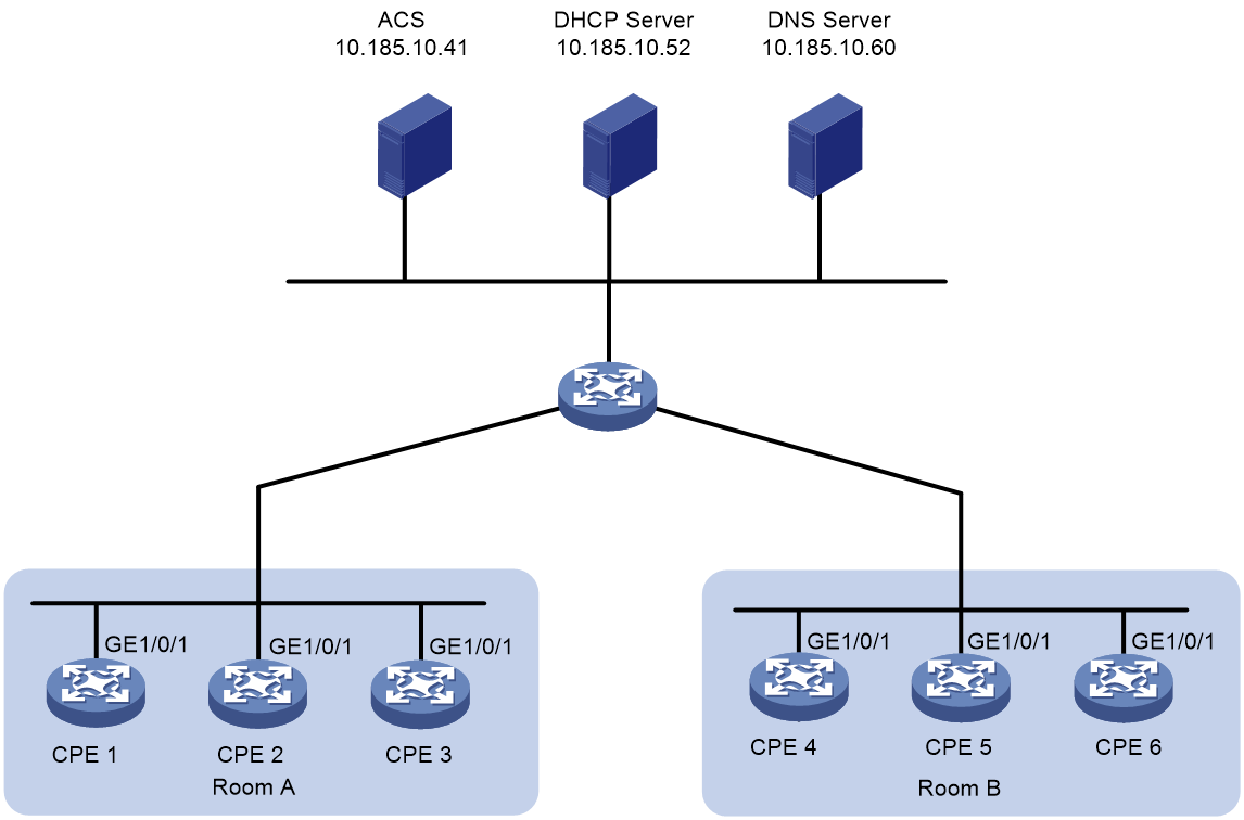
Table 7 shows the ACS parameters for the CPEs to connect to the ACS.
|
Item |
Setting |
|
Preferred ACS URL |
https://10.185.10.41:9090 |
|
ACS username |
admin |
|
ACS password |
12345 |
Table 8 lists serial numbers of the CPEs.
|
Room |
Device |
Serial number |
|
A |
CPE 1 |
210231A95YH10C000045 |
|
CPE 2 |
210235AOLNH12000010 |
|
|
CPE 3 |
210235AOLNH12000015 |
|
|
B |
CPE 4 |
210235AOLNH12000017 |
|
CPE 5 |
210235AOLNH12000020 |
|
|
CPE 6 |
210235AOLNH12000022 |
Configuring the ACS
Figures in this section are for illustration only.
To configure the ACS:
1. Log in to the ACS:
a. Launch a Web browser on the ACS configuration terminal.
b. In the address bar of the Web browser, enter the ACS URL and port number. This example uses https://10.185.10.41:8080/imc.
c. On the login page, enter the ACS login username and password, and then click Login.
2. Create a CPE group for each equipment room:
a. Select Service > BIMS > CPE Group from the top navigation bar.
The CPE Group page appears.
Figure 8 CPE Group page
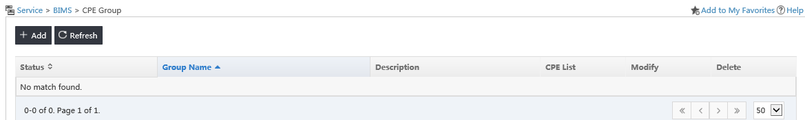
b. Click Add.
c. Enter a username, and then click OK.
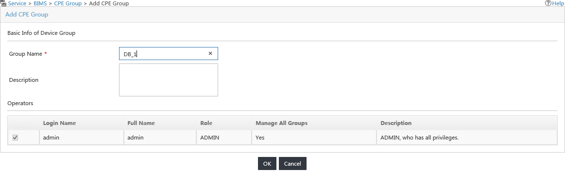
d. Repeat the previous two steps to create a CPE group for CPEs in Room B.
3. Add CPEs to the CPE group for each equipment room:
a. Select Service > BIMS > Resource Management > Add CPE from the top navigation bar.
b. On the Add CPE page, configure the following parameters:
- Authentication Type—Select ACS UserName.
- CPE Name—Enter a CPE name.
- ACS Username—Enter admin.
- ACS Password Generated—Select Manual Input.
- ACS Password—Enter a password for ACS authentication.
- ACS Confirm Password—Re-enter the password.
- CPE Model—Select the CPE model.
- CPE Group—Select the CPE group.
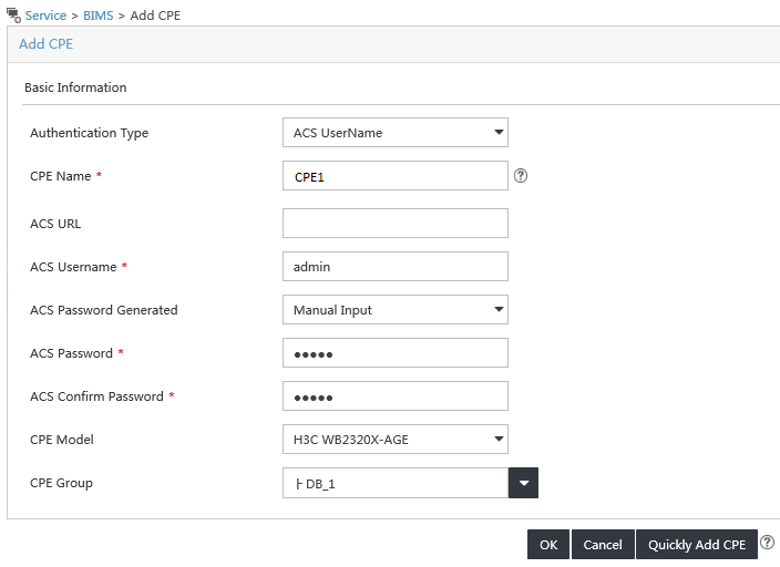
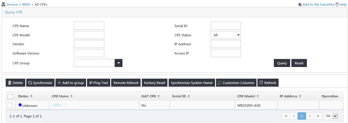
c. Click OK.
d. Verify that the CPE has been added successfully from the All CPEs page.
Figure 11 Viewing CPEs
e. Repeat the previous steps to add CPE 2 and CPE 3 to the CPE group for Room A, and add CPEs in Room B to the CPE group for Room B.
4. Configure a configuration template for each equipment room:
a. Select Service > BIMS > Configuration Management > Configuration Templates from the top navigation bar.
Figure 12 Configuration Templates page
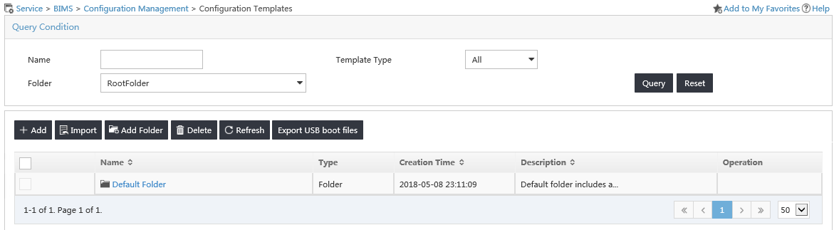
b. Click Import.
c. Select a source configuration file, select Configuration Segment as the template type, and then click OK.
The created configuration template will be displayed in the Configuration Template list after a successful file import.
|
|
IMPORTANT: If the first command in the configuration template file is system-view, make sure no characters exist in front of the command. |
Figure 13 Importing a configuration template
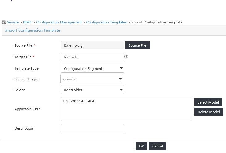
Figure 14 Configuration Template list
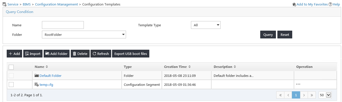
d. Repeat the previous steps to configure a configuration template for Room B.
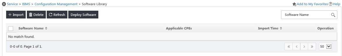
5. Add software library entries:
a. Select Service > BIMS > Configuration Management > Software Library from the top navigation bar.
Figure 15 Software Library page
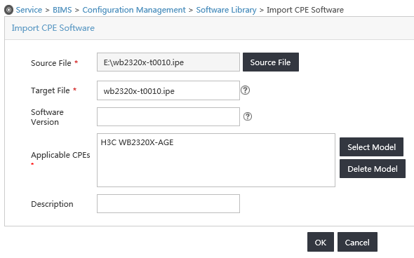
b. Click Import.
c. Select a source file, and then click OK.
Figure 16 Importing CPE software
d. Repeat the previous steps to add software library entries for CPEs of different models.
6. Create an auto-deployment task for each equipment room:
a. Select Service > BIMS > Configuration Management > Deployment Guide from the top navigation bar.
Figure 17 Deployment Guide
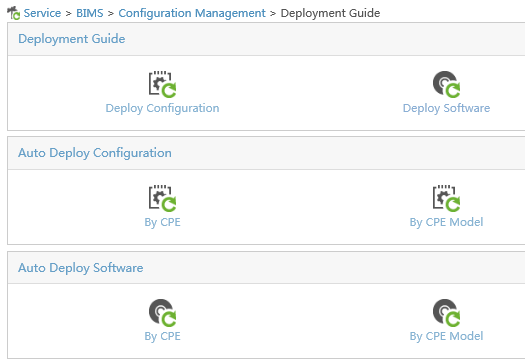
b. Click By CPE Model from the Auto Deployment Configuration field.
c. Select a configuration template, select Startup Configuration from the File Type to be Deployed list, and click Select Model to select CPEs in Room A. Then, click OK.
You can search for CPEs by CPE group.
Figure 18 Auto deployment configuration
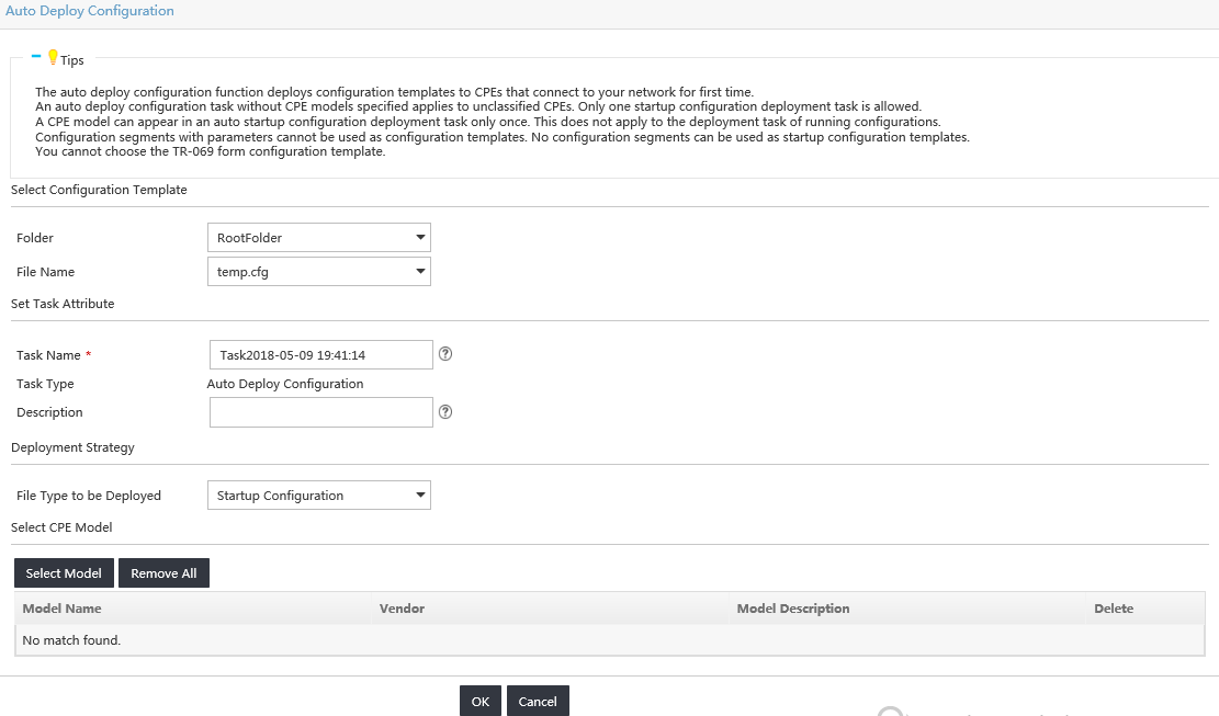
d. Click OK on the Auto Deploy Configuration page.
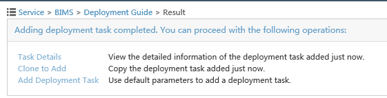
Figure 19 Operation result
e. Repeat the previous steps to add a deployment task for CPEs in Room B.
Configuring the DHCP server
In this example, an H3C device is operating as the DHCP server.
1. Configure an IP address pool to assign IP addresses and DNS server address to the CPEs. This example uses subnet 10.185.10.0/24 for IP address assignment.
# Enable DHCP.
<DHCP_server> system-view
[DHCP_server] dhcp enable
# Enable DHCP server on VLAN-interface 1.
[DHCP_server] interface vlan-interface 1
[DHCP_server-Vlan-interface1] dhcp select server
[DHCP_server-Vlan-interface1] quit
# Exclude the DNS server address 10.185.10.60 and the ACS IP address 10.185.10.41 from dynamic allocation.
[DHCP_server] dhcp server forbidden-ip 10.185.10.41
[DHCP_server] dhcp server forbidden-ip 10.185.10.60
# Create DHCP address pool 0.
[DHCP_server] dhcp server ip-pool 0
# Assign subnet 10.185.10.0/24 to the address pool, and specify the DNS server address 10.185.10.60 in the address pool.
[DHCP_server-dhcp-pool-0] network 10.185.10.0 mask 255.255.255.0
[DHCP_server-dhcp-pool-0] dns-list 10.185.10.60
2. Configure DHCP Option 43 to contain the ACS URL, username, and password in hexadecimal format.
[DHCP_server-dhcp-pool-0] option 43 hex 013B68747470733A2F2F6163732E64617461626173653A393039302F616373207669636B79203132333435
Configuring the DNS server
Map https://acs.database:9090 to https://10.185.1.41:9090 on the DNS server. For more information about DNS configuration, see DNS server documentation.
Connecting the CPEs to the network
# Connect CPE 1 to the network, and then power on the CPE. (Details not shown.)
# Log in to CPE 1 and configure its interface GigabitEthernet 1/0/1 to use DHCP for IP address acquisition. At startup, the CPE obtains the IP address and ACS information from the DHCP server to initiate a connection to the ACS. After the connection is established, the CPE interacts with the ACS to complete autoconfiguration.
<CPE1> system-view
[CPE1] interface gigabitethernet 1/0/1
[CPE1-GigabitEthernet1/0/1] ip address dhcp-alloc
# Repeat the previous steps to configure the other CPEs.
Verifying the configuration
# Execute the display current-configuration command to verify that the running configurations on CPEs are the same as the configurations issued by the ACS.
Example: Automatically deploying base stations through IPv4 CWMP on the same subnet as the ACS
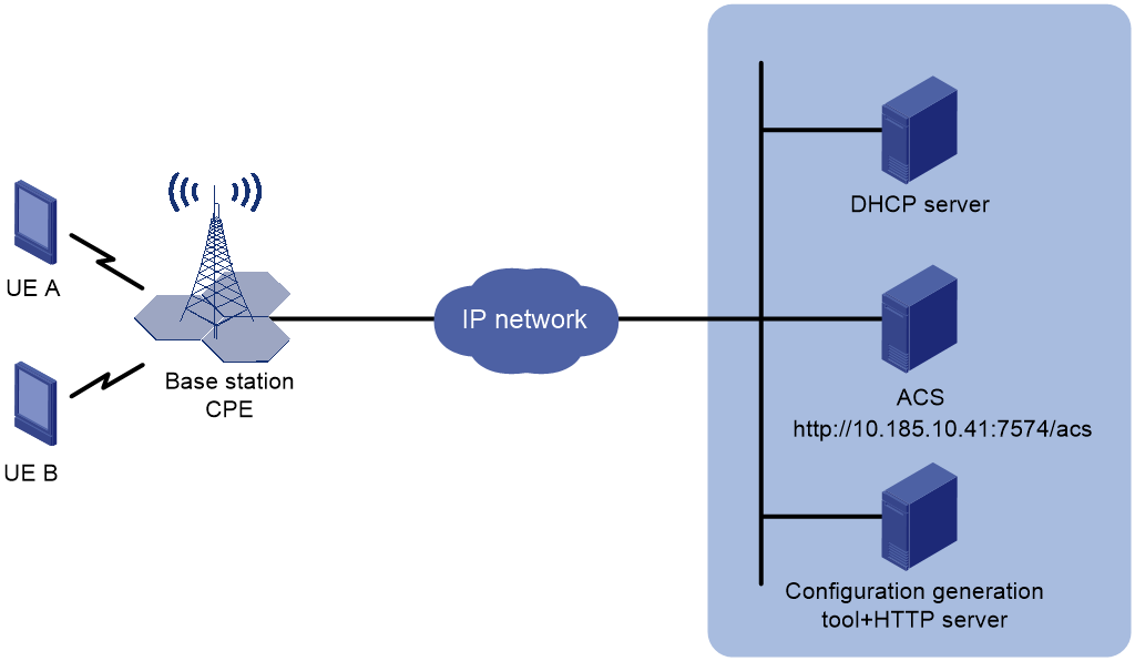
Network configuration
As shown in Figure 20, a carrier has built a new base station. Configure CWMP to meet the following requirements:
· The base station is assigned an IP address automatically from the 10.185.10.0/24 subnet through the DHCP server.
· The network administrator creates a base station startup file in standard XML format by using a configuration generation tool and stores the file on an HTTP server.
· The base station is automatically deployed by using CWMP and the XML base station startup file to provide wireless access services for users in the community.
Analysis
1. Configure the DHCP server to assign IP addresses and ACS parameters to the base station (as a CPE).
2. The ACS notifies the CPE to download the base station startup file in XML format.
3. The CPE automatically downloads the base station startup file from the HTTP server and restarts with it.
Prerequisites
Use a configuration generation tool to generate a base station startup file named startup.xml in standard XML format for the base station, and save it on an HTTP server.
Configuring the DHCP server
1. Configure an address pool to allocate IP addresses and DNS servers to the CPE:
In this example, use the 10.185.10.0/24 subnet for address allocation.
# Enable DHCP.
<DHCP_server> system-view
[DHCP_server] dhcp enable
# Enable the DHCP server on VLAN-interface 1.
[DHCP_server] interface vlan-interface 1
[DHCP_server-Vlan-interface1] dhcp select server
[DHCP_server-Vlan-interface1] quit
# Exclude the address of the ACS server from dynamic address allocation.
[DHCP_server] dhcp server forbidden-ip 10.185.10.41
# Specify the subnet for dynamic allocation in DHCP address pool 0.
[DHCP_server] dhcp server ip-pool 0
[DHCP_server-dhcp-pool-0] network 10.185.10.0 mask 255.255.255.0
2. Configure option 43.
The option includes ACS URL https://10.185.10.41:7547/acs, username admin, and password 12345.
# Convert the ACS URL, username, and password to ASCII codes. The ASCII codes for URL http://10.185.10.41:7547/acs are 68 74 74 70 73 3A 2F 2F 31 30 2E 31 38 35 2E 31 30 2E 34 31 3A 37 35 34 37 2F 61 63 73. The ASCII codes for username admin are 61 64 6D 69 6E, and the ASCII codes for password 12345 are 31 32 33 34 35.
[DHCP_server-dhcp-pool-0] option 43 hex 012868747470733A2F2F31302E3138352E31302E34313A373534372F6163732061646D696E203132333435
Connecting the CPE to the network
Power on the base station (CPE) and connect a network cable to it. Start the base station with its factory settings. Then, the base station will be automatically deployed and provide wireless access services for users in the community.
Connecting the ACS
Issue an instruction to the CPE to instruct the CPE to use the XML file for automatic base station deployment, and include the URL of the base station startup file in the instruction.
Verifying the configuration
Verify that mobile endpoints UE A and UE B can access mobile networks.
Example: Automatically deploying base stations through IPv6 CWMP on the same subnet as the ACS
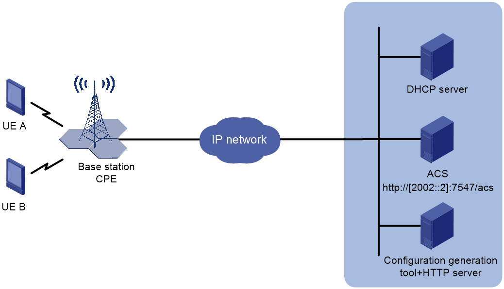
Network configuration
As shown in Figure 21, a carrier has built a new base station. Configure CWMP to meet the following requirements:
· The base station is assigned an IPv6 address automatically from the 2002::/96 subnet through the DHCP server.
· The network administrator creates a base station startup file in standard XML format by using a configuration generation tool and stores the file on an HTTP server.
· The base station is automatically deployed by using CWMP and the XML base station startup file to provide wireless access services for users in the community.
Analysis
1. Configure the DHCP server to assign IP addresses and ACS parameters to the base station (as a CPE).
2. The ACS notifies the CPE to download the base station startup file in XML format.
3. The CPE automatically downloads the base station startup file from the HTTP server and restarts with it.
Prerequisites
Use a configuration generation tool to generate a base station startup file named startup.xml in standard XML format for the base station, and save it on an HTTP server.
Configuring the DHCP server
1. Configure an address pool to allocate IP addresses and DNS servers to the CPE:
In this example, use the 2002::/96 subnet for address allocation.
# Enable DHCP.
<DHCP_server> system-view
[DHCP_server] dhcp enable
# Enable the DHCP server on VLAN-interface 1.
[DHCP_server] interface vlan-interface 1
[DHCP_server-Vlan-interface1] ipv6 dhcp select server
[DHCP_server-Vlan-interface1] quit
# Specify the subnet for dynamic allocation in DHCP address pool 1.
[DHCP_server] ipv6 dhcp pool 1
[DHCP_server-dhcp-pool-1] network 2002::/96
2. Configure the corresponding vendor ID:
# Configure the corresponding vendor ID.
[DHCP_server-dhcp6-pool-1]vendor-specific 3561
# Configure the suboption corresponding to the vendor ID. Convert the ACS URL, username, and password into ASCII codes. The ASCII codes for URL https://[2002::2]:7547/acs are 68 74 74 70 73 3A 2F 2F 5B 32 30 30 32 3A 3A 32 5D 3A 37 35 34 37 2F 61 63 73. The ASCII codes for username admin are 61 64 6D 69 6E, and the ASCII codes for password 12345 are 31 32 33 34 35.
[DHCP_server-dhcp6-pool-1-vs-3561] suboption 1 hex 68747470733A2F2F5B323030323A3A325D3A373534372F6163732061646D696E203132333435
Connecting the CPE to the network
Power on the base station (CPE) and connect a network cable to it. Start the base station with its factory settings. Then, the base station will be automatically deployed and provide wireless access services for users in the community.
Connecting the ACS
Issue an instruction to the CPE to instruct the CPE to use the XML file for automatic base station deployment, and include the URL of the base station startup file in the instruction.
Verifying the configuration
Verify that mobile endpoints UE A and UE B can access mobile networks.
Example: Automatically deploying base stations through IPv4 CWMP on a different subnet from the ACS
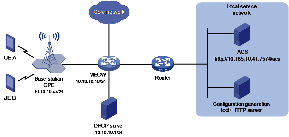
Network requirements
As shown in Figure 22, a carrier has built a new base station. Configure CWMP to meet the following requirements:
· The base station is assigned an IP address automatically from the 10.10.10.0/24 subnet through the DHCP server.
· The network administrator creates a base station startup file in standard XML format by using a configuration generation tool and stores the file on an HTTP server.
· The base station is automatically deployed by using CWMP and the XML base station startup file to provide wireless access services for users in the community.
Analysis
1. Configure the DHCP server to assign IP addresses and ACS parameters to the base station (as a CPE).
2. The ACS notifies the CPE to download the base station startup file in XML format.
3. The CPE automatically downloads the base station startup file from the HTTP server and restarts with it.
Prerequisites
Use a configuration generation tool to generate a base station startup file named startup.xml in standard XML format for the base station, and save it on an HTTP server.
Configuring the DHCP server
1. Configure an address pool to allocate IP addresses and DNS servers to the CPE:
In this example, use the 10.185.10.0/24 subnet for address allocation.
# Enable the DHCP service.
<DHCP_server> system-view
[DHCP_server] dhcp enable
# Configure VLAN-interface 1 to operate in DHCP server mode.
[DHCP_server] interface vlan-interface 1
[DHCP_server-Vlan-interface1] dhcp select server
[DHCP_server-Vlan-interface1] quit
# Exclude the IP address of the ACS server from auto allocation.
[DHCP_server] dhcp server forbidden-ip 10.185.10.41
# Specify the subnet for DHCP address pool 0.
[DHCP_server] dhcp server ip-pool 0
[DHCP_server-dhcp-pool-0] network 10.10.10.0 mask 255.255.255.0
2. Configure DHCP option 43:
# Specify the CPE SN as 210235A2G1B205000027. The corresponding hexadecimal value is 32 31 30 32 33 35 41 32 47 31 42 32 30 35 30 30 30 30 32 37.
[DHCP_server-dhcp-pool-0] option 43 sub-option 01 hex 3231303233354132473142323035303030303237
# Specify the CPE OUI as 000FE2. The corresponding hexadecimal value is 30 30 30 46 45 32.
[DHCP_server-dhcp-pool-0] option 43 sub-option 02 hex 303030464532
# Specify the CPE IP address mask as 255.255.255.0. The corresponding hexadecimal value is 32 35 35 2e 32 35 35 2e 32 35 35 2e 30.
[DHCP_server-dhcp-pool-0] option 43 sub-option 04 hex 3235352e3235352e3235352e30
# Specify the CPE IPv4 gateway address as 10.10.10.10. The corresponding hexadecimal value is 31 30 2e 31 30 2e 31 30 2e 31 30.
[DHCP_server-dhcp-pool-0] option 43 sub-option 05 hex 31302e31302e31302e3130
# Specify the ID of the VLAN to be created on the CPE as 10. The corresponding hexadecimal value is 31 30.
[DHCP_server-dhcp-pool-0] option 43 sub-option 06 hex 3130
# Specify the ACS URL for the CPE as https://10.185.10.41:7547/acs. The corresponding hexadecimal value is 68 74 74 70 73 3A 2F 2F 31 30 2E 31 38 35 2E 31 30 2E 34 31 3A 37 35 34 37 2F 61 63 73.
[DHCP_server-dhcp-pool-0] option 43 sub-option 07 hex 68747470733A2F2F31302E3138352E31302E34313A373534372F616373
# Specify the username for the CPE to access the ACS as admin. The corresponding ASCII code is 61 64 6D 69 6E.
[DHCP_server-dhcp-pool-0] option 43 sub-option 07 hex 61646D696E3
# Specify the password for the CPE to access the CPE as 12345. The corresponding ASCII code is 31 32 33 34 35.
[DHCP_server-dhcp-pool-0] option 43 sub-option 07 hex 3132333435
Connecting the CPE to the network
Power on the base station (CPE) and connect a network cable to it. Start the base station with its factory settings. Then, the base station will be automatically deployed and provide wireless access services for users in the community.
Configuring the ACS
Issue an instruction to the CPE to instruct the CPE to use the XML file for automatic base station deployment, and include the URL of the base station startup file in the instruction.
Verifying the configuration
Verify that mobile endpoints UE A and UE B can access mobile networks.
Example: Automatically deploying base stations through IPv6 CWMP on a different subnet from the ACS
Network requirements
As shown in Figure 23, a carrier has built a new base station. Configure CWMP to meet the following requirements:
· The base station is assigned an IPv6 address automatically from the 2001::/96 subnet through the DHCP server.
· The network administrator creates a base station startup file in standard XML format by using a configuration generation tool and stores the file on an HTTP server.
· The base station is automatically deployed by using CWMP and the XML base station startup file to provide wireless access services for users in the community.

Analysis
1. Configure the DHCP server to assign IP addresses and ACS parameters to the base station (as a CPE).
2. The ACS notifies the CPE to download the base station startup file in XML format.
3. The CPE automatically downloads the base station startup file from the HTTP server and restarts with it.
Prerequisites
Use a configuration generation tool to generate a base station startup file named startup.xml in standard XML format for the base station, and save it on an HTTP server.
Configuring the DHCP server
1. Configure an address pool to allocate IP addresses and DNS servers to the CPE:
In this example, use the 2001::/96 subnet for address allocation.
# Enable the DHCP service.
<DHCP_server> system-view
[DHCP_server] dhcp enable
# Configure VLAN-interface 1 to operate in DHCP server mode.
[DHCP_server] interface vlan-interface 1
[DHCP_server-Vlan-interface1] ipv6 dhcp select server
[DHCP_server-Vlan-interface1] quit
# Specify a subnet for DHCP address pool 1.
[DHCP_server] ipv6 dhcp pool 1
[DHCP_server-dhcp6-pool-1] network 2001::/96
2. Specify the vendor ID.
[DHCP_server-dhcp6-pool-1] vendor-specific 3561
3. Configure the sub-options.
# Specify the CPE SN as 210235A2G1B205000027. The corresponding hexadecimal value is 32 31 30 32 33 35 41 32 47 31 42 32 30 35 30 30 30 30 32 37.
[DHCP_server-dhcp-pool-0] option 43 sub-option 01 hex 3231303233354132473142323035303030303237
# Specify the CPE OUI as 000FE2. The corresponding hexadecimal value is 30 30 30 46 45 32.
[DHCP_server-dhcp-pool-0] option 43 sub-option 02 hex 303030464532
# Specify the CPE IP address prefix length as 96. The corresponding hexadecimal value is 39 36.
[DHCP_server-dhcp-pool-0] option 43 sub-option 04 hex 3936
# Specify the CPE IPv4 gateway address as 2001::10. The corresponding hexadecimal value is 32 30 30 31 3a 3a 31 30.
[DHCP_server-dhcp-pool-0] option 43 sub-option 05 hex 31302e31302e31302e3130
# Specify the ID of the VLAN to be created on the CPE as 10. The corresponding hexadecimal value is 31 30.
[DHCP_server-dhcp-pool-0] option 43 sub-option 06 hex 3130
# Specify the ACS URL for the CPE to connect as https://[2002::2]:7547/acs. The corresponding hexadecimal value is 68 74 74 70 73 3A 2F 2F 5B 32 30 30 32 3A 3A 32 5D 3A 37 35 34 37 2F 61 63 73.
[DHCP_server-dhcp6-pool-1] suboption 07 hex 68747470733A2F2F5B323030323A3A325D3A373534372F616373
# Specify the username for the CPE to access the ACS as admin. The corresponding ASCII code is 61 64 6D 69 6E.
[DHCP_server-dhcp6-pool-1] suboption 08 hex 61646D696E3
# Specify the username for the CPE to access the ACS as 12345. The corresponding ASCII code is 31 32 33 34 35.
[DHCP_server-dhcp6-pool-1] suboption 09 hex 3132333435
Connecting the CPE to the network
Power on the base station (CPE) and connect a network cable to it. Start the base station with its factory settings. Then, the base station will be automatically deployed and provide wireless access services for users in the community.
Configuring the ACS
Issue an instruction to the CPE to instruct the CPE to use the XML file for automatic base station deployment, and include the URL of the base station startup file in the instruction.
Verifying the configuration
Verify that mobile endpoints UE A and UE B can access mobile networks.