- Table of Contents
- Related Documents
-
| Title | Size | Download |
|---|---|---|
| 01-Text | 4.18 MB |
Examining the installation environment
Checking power distribution or power supply environment
Mounting the switch on a DIN rail
Mounting the switch on a DIN rail
Grounding the switch by using a grounding strip
Grounding the switch with a grounding conductor buried in the earth ground
Verifying the connection after grounding the switch
Connecting the DC power cord for a fixed DC power supply (through a terminal block)
4 Maintenance and troubleshooting
10/100/1000BASE-T Ethernet port
10/100/1000BASE-T autosensing Ethernet port LED
1 Preparing for installation
|
|
CAUTION: Install and use the switch based on the compliance and safety manual, and environment and installation method requirements described in this document. Otherwise, H3C shall not be liable for any consequence. |
This document is applicable to the IE4300U switch series. Table1-1 describes the IE4300U switch models.
Table1-1 IE4300U switch models
|
Switch series |
Switch model |
Product code (PID) |
|
IE4300U industrial switch series |
IE4300U-5E |
LS-IE4300U-5E |
|
IE4300U-8E |
LS-IE4300U-8E-H1 |
|
|
IE4300U-10P |
LS-IE4300U-10P-H1 |
|
|
IE4300U-10P-PWR |
LS-IE4300U-10P-PWR |
Safety recommendations
|
|
WARNING! When the ambient temperature exceeds 60°C (140°F), the outer surface temperature of the switch might exceed 70°C (158°F). You must install the switch in a restricted access area. To avoid burns, take protective measures when working with the switch. |
To avoid bodily injury or damage to the switch, read the following safety recommendations carefully before working with the switch. Note that the recommendations do not cover every possible hazardous condition.
· Before cleaning the switch, remove all power cords from the switch. Do not clean the switch with wet cloth or liquid.
· Do not place the switch near water or in a damp environment. Prevent water or moisture from entering the switch chassis.
· Do not place the switch on an unstable case or desk.
· Ensure adequate ventilation for the switch and keep the protective vent of the switch unblocked.
· Make sure the power source voltage meets the requirements of the switch.
· To avoid electrical shocks, do not open the chassis while the switch is operating. As a best practice, do not open the chassis even if the switch is powered off.
· When installing the switch, always wear an ESD wrist strap. Make sure the wrist strap makes good skin contact and is reliably grounded.
|
|
NOTE: The switch is a class A device and might cause radio interference in a residential area. Take adequate measures as required. |
Examining the installation environment
To ensure correct operation of your switch, make sure the installation environment meets the requirements listed in Table1-2.
Table1-2 Checking list for the installation environment
|
Item |
Requirements |
|
Ventilation and heat dissipation |
To ensure correct operation of your device, make sure the installation environment is adequately ventilated to prevent the device from overheating. · Ensure a minimum clearance of 10 cm (3.94 in) around the chassis. · Do not install the device near a heat source, for example, a stove or heater. · Ensure air ventilation in the installation environment. · Do not block the ventilation holes in the device or power adapter. |
|
Anti-moisture |
Water or moisture might damage the circuits of the device. · Do not place the device near water or in a damp environment. · Install the switch in a clean, dry, and ventilated place where temperature is controlled in a stable range. · Make sure the installation environment is free from water leakage or condensation. If required, install a dehumidification device (such as an air conditioner with a dehumidification function or a dedicated dehumidifier). · Do not operate the device under or near the water source, such as the wash basin, laundry room, or areas with high humidity. · Do not touch the device with wet hands. |
|
Lightning protection |
Ground the switch correctly and verify the grounding. · If you ground the switch by using a grounding strip, make sure the grounding resistance of the grounding strip in the equipment room is less than 1Ω. · If you ground the switch by using a grounding conductor buried in the earth ground, make sure the grounding resistance of the grounding conductor in the ground is less than 10Ω. · Route the signal cables along indoor walls. If cables must be routed outdoors, bury the cables in the earth ground, or thread the cables through steel tubes. Install a signal lightning arrester with a nominal discharge current for a corresponding network interface. · Keep the signal cables far from power cords and lightning rod down conductors. · As a best practice, route power cords indoors. If an AC power cord is routed from outdoors, connect the AC power cord first to a power lightning arrester before leading it to the AC power port on the switch. Make sure the power lightning arrester has a nominal discharge current and the total length of the power cord from the power lighting arrester to the power port on the switch is less than 5 m (16.40 ft). · Ground the switch, rack, independent power supplies, and lightning arresters separately. · You must ground optical fibers with reinforcing metal stiffener from outdoors on an optical distribution frame (ODF) or fiber splice enclosure. |
|
Cable routing |
Do not run an Ethernet cable and power cord in parallel. · Route different types of cables separately. · Keep power cords a minimum of 5 cm (1.97 in) away from other cables. |
|
Mechanical environment |
As a best practice, make sure the mechanical class of the environment is not above 4M4 if you install the switch in an outdoor environment. NOTE: 4M represents the mechanical environment condition defined by GB/T 4798.4. It has eight classes. The 4M4 class refers to places impacted by machines, running vehicles, or ground blasting or piling. |
|
Dust and water resistance |
If you install the switch in an outdoor environment, make sure the installation and operating environments meet the requirements of IP55 rating protection. NOTE: IP indicates International Protection Rating. The first number "5" refers to the rating for preventing the solid particle from entering the cabinet. An outdoor cabinet cannot prevent dust intrusion perfectly, but the dust cannot damage the device. The second number "5" refers to the rating for preventing water from entering the cabinet. Water projected in jets against the enclosure from any direction cannot damage the device. |
|
ESD prevention |
· Ground the switch correctly. · To avoid ESD damage to the device or components, always wear an ESD wrist strap when you install or remove the device. · Make sure the wrist strap has good skin contact and is reliably grounded. |
|
Corrosive gas prevention |
The installation site must be free from corrosive gases such as acid gases and alkaline gases. |
|
EMI |
· If AC power is used, use a single-phase three-wire power receptacle with protection earth (PE) to filter interference from the power grid. · Keep the device far away from radio transmitting stations, radar stations, and high-frequency devices. · Use electromagnetic shielding, for example, shielded interface cables, when necessary. |
Checking power distribution or power supply environment
Table1-3 Requirements for power distribution or power supply environment
|
Item |
Requirements |
|
Preparation |
The power supply must be available before you install the switch. |
|
Voltage |
The voltage provided to the switch must be within the operating voltage range. For the operating voltage range, see the hardware information and specifications for the switch. |
|
Power receptacle and cables |
· If the external power supply system provides an AC power outlet, use a country-specific AC power cord. Make sure the PE wire of the AC power supply is grounded reliably. · If the external power supply system provides a DC distribution box, prepare DC power cords yourself. · The switch came with a terminal block connected to each power receptacle. No power cord is provided with the switch. Prepare compatible copper power wires yourself as required. For information about the wire diameter and connection requirements, see "Table2-3." |
Laser safety
|
|
WARNING! The switch is a Class 1 laser device. Disconnected optical fibers or transceiver modules might emit invisible laser light. Do not stare into beams or view directly with optical instruments when the switch is operating. |
Installation tools
No installation tools are provided with the switch. Prepare the following tools yourself:
· Flat-head screwdriver
· Phillips screwdriver
· ESD wrist strap
· Needle-nose pliers
· Diagonal pliers
· Crimping tool
2 Installing the switch
|
|
CAUTION: Keep the tamper-proof seal on a mounting screw on the chassis cover intact, and if you want to open the chassis, contact H3C for permission. Otherwise, H3C shall not be liable for any consequence caused thereby. |
Mounting the switch on a DIN rail
DIN bracket
The switch came with a DIN bracket installed on it.
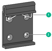
|
(1) Metal spring |
(2) Screw hole |
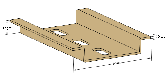
Figure2-1 shows the dimensions of the DIN rails applicable to the DIN bracket. Prepare the DIN rails as required.
Table2-1 Applicable DIN rail dimensions
|
Switch model |
DIN rail dimensions (H × W × D) |
|
IE4300U-5E IE4300U-8E IE4300U-10P IE4300U-10P-PWR |
7.5 × 35 × 1 mm (0.30 × 1.38 × 0.04 in) |
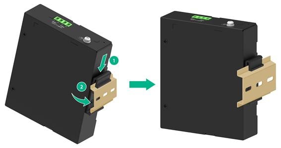
Mounting the switch on a DIN rail
1. Wear an ESD wrist strap and make sure it makes good skin contact and is reliably grounded.
2. As shown by callout 1 in Figure2-3, position the switch so that the spring of the DIN bracket compresses against the upper edge of the DIN rail.
3. As shown by callout 2 in Figure2-3, rotate the switch down toward the DIN rail until the DIN bracket clicks.
Figure2-3 Mounting the switch on a DIN rail
Connect the grounding cable
|
|
WARNING! · Correctly connecting the grounding cable for the switch is crucial to lightning protection, ESD, and EMI protection. · Do not connect the positive pole or negative pole of a DC power receptacle to the ground. To ground the switch, use the grounding cable and grounding screws. |
|
|
NOTE: The power and grounding terminals in this section are for illustration only. |
To protect against the following types of issues, use a grounding cable to connect the switch to the earthing facility at the installation site:
· Bodily injury from electric shocks.
· Device and power and data line damages.
· Electrical fires, lightning strokes, electromagnetic coupling interference, and ESD damages.
Select a grounding method based on the installation environment.
Grounding the switch by using a grounding strip
|
|
CAUTION: · Connect the grounding cable to the grounding strip in the equipment room. Do not connect it to a fire main or lightning rod. · To guarantee the grounding effect and avoid switch damage, use the grounding cable provided with the switch to connect the switch to a grounding strip in the equipment room. |
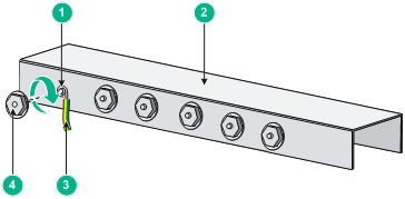
Connecting the grounding cable to the chassis
1. Remove the grounding screw from the grounding hole in the chassis.
2. Use the grounding screw to attach the ring terminal of the grounding cable to the grounding screw hole, and then fasten the screw.
Figure2-4 Connecting the grounding cable to the chassis (IE4300U-5E)
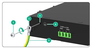
|
(1) Grounding screw |
(2) Ring terminal |
|
(3) Grounding hole |
(4) Grounding sign |
|
(5) Grounding cable |
|
Connecting the grounding cable to a grounding strip
1. Cut the grounding cable to a length according to the distance between the switch and the grounding strip.
2. Peel 20 mm (0.79 in) of insulation sheath by using a wire stripper. Use needle-nose pliers to bend the bare metal part to the shape as shown in Figure2-5. Make sure the bended part can be securely attached to the grounding post on the grounding strip.
3. Attach the bended part of the grounding cable to the grounding post and use the hex nut to fasten the bended part to the post.
Figure2-5 Connecting the grounding cable to a grounding strip
|
(1) Grounding post |
(2) Grounding strip |
|
(3) Grounding cable |
(4) Hex nut |
Grounding the switch with a grounding conductor buried in the earth ground
If the installation site does not have grounding strips, but earth ground is available, hammer a 2.5 m (8.20 ft) or longer angle iron or steel tube into the earth ground to act as a grounding conductor. Make sure a minimum of 0.7 m (2.30 ft) is left between the top of the grounding conductor and the ground. In cold areas, bury the grounding conductor below the frozen soil layer. In areas with thin soil or rocky gravel, determine the depth for burying the grounding conductor based on the actual condition.
If zinc-coated steel is used, the following dimension requirements must be met:
· Angle iron—A minimum of 50 × 50 × 5 mm (1.97 × 1.97 × 0.20 in).
· Steel tube—A minimum of 3.5 mm (0.14 in) in thickness.
· Flat steel—A minimum of 40 × 4 mm (1.57 × 0.16 in).
· Round steel—A minimum of 10 mm (0.39 in).
Weld the yellow-green grounding cable to the angel iron or steel tube and treat the joint for corrosion protection.
Figure2-6 Grounding the switch by burying the grounding conductor into the earth ground (IE4300U-5E)
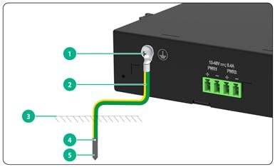
|
(1) Grounding screw |
(2) Grounding cable |
(3) Earth |
|
(4) Joint |
(5) Grounding conductor |
|
Verifying the connection after grounding the switch
Verify the connection after grounding the switch as follows:
· If you ground the switch by using a grounding strip, perform the following tasks:
a. Use a multimeter to measure the resistance between the switch grounding terminal and grounding point, and make sure the resistance is less than 0.1Ω.
b. Use a grounding resistance tester to measure the grounding resistance of the grounding strip, and make sure the grounding resistance is less than 1Ω.
· If you ground the switch with a grounding conductor buried in the earth ground, perform the following tasks:
a. Use a multimeter to measure the resistance between the switch grounding terminal and grounding point, and make sure the resistance is less than 0.1Ω.
b. Use a grounding resistance tester to measure the grounding resistance of the angle iron in the ground, and make sure the grounding resistance is less than 10Ω. For locations with high soil resistivity, sprinkle some resistance reducer to reduce soil resistivity or replace soil around the grounding strip with soil with lower resistance.
For information about resistance measurement, see H3C Network Devices Lightning Protection Guide.
Connecting power cords
Table2-2 Power cord connection procedures at a glance
|
Switch model |
Connection procedure reference |
Description |
|
IE4300U-8E IE4300U-10P IE4300U-10P-PWR |
Connecting the DC power cord for a fixed DC power supply (through a terminal block) |
The switch supports dual DC inputs for 1+1 power redundancy. |
Table2-3 Power cord specifications
|
Switch model |
Minimum conductor cross-sectional area |
Maximum conductor cross-sectional area |
|
IE4300U-5E IE4300U-8E IE4300U-10P IE4300U-10P-PWR |
0.5 mm2 or 20 AWG |
3 mm2 or 12 AWG |
Connecting the DC power cord for a fixed DC power supply (through a terminal block)
|
|
CAUTION: · Make sure each power cord has a separate circuit breaker. · Turn off the circuit breaker before connecting the power cord. · To avoid connection mistakes, identify the positive (+) and negative (-) marks above the DC power receptacle. · To connect the switch to a DC power source in the equipment room, identify the positive (+) and negative (-) marks above the DC power receptacle to ensure correct connections. |
The switch came with a terminal block installed in each DC power receptacle.
You can use the following methods to connect a DC power cord to the switch:
· Connect the DC power cord directly to the terminal block installed on the DC power receptacle.
· Connect the DC power cord to the terminal block, and then secure the terminal block to the DC power receptacle.
In this section, the second method is used as an example.
To connecting the DC power cord for a fixed DC power supply:
1. Use a wire stripper to strip the heat-shrink tubes off the two-wire power cord on one end, and then strip the electrical insulation off to make sure about 7 mm (0.28 in) of the wire reaches out. Repeat this step for the other end.
2. Orient the terminal block with upside up and identify the positive (+) and negative (-) connections on the terminal block.
If you orient the terminal block upside down, you cannot insert it into the power receptacle.
3. As shown by callout 1 in Figure2-7, insert the wires into the terminal block, with the positive wire (red) to the positive connection and negative wire (black) to the negative connection.
4. As shown by callout 2 in Figure2-7, use a flat-head screwdriver to fasten the screws at the top of the terminal block to secure the wires to the connector.
5. As shown by callout 3 in Figure2-7, connect the terminal block to a DC power receptacle. Use a flat-head screwdriver to fasten the screws on the terminal block to secure the terminal block to the power receptacle.
6. Connect the other ends of the wires to a DC power source.
Figure2-7 Connecting a DC power cord for the switch (IE4300U-5E)
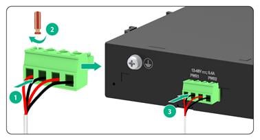
|
|
NOTE: The wire colors in the preceding figure are for illustration only. |
Verifying the installation
After you complete the installation, verify the following information:
· There is enough space around the switch for heat dissipation.
· The DIN rail is stable.
· The grounding cable is connected correctly.
· The power source is as required by the switch.
· The power cord is correctly connected.
· If part of the network cable for a port is routed outdoors, verify that a network port lightning protector is used for the port.
· If a power line is routed from outdoors, verify that a surge protected power strip is used for the switch.
3 Accessing the switch
|
|
IMPORTANT: As a best practice, use the following Web browsers to access the Web management interface of the switch: · Google Chrome 109.0.5414.120 or higher. · Mozilla Firefox 110.0 or higher. · Microsoft Edge 89.0.774.68 or higher. The Internet Explorer Web browser is not supported. |
For more information about Web management of the switch, see H3C IE4300U Switch Series Web Configuration Guide.
To access the switch:
1. Connect the PC to the LAN port on the switch.
2. Configure an IP address in subnet 192.168.0.233/24 for the PC.
3. Check the proxy settings of the PC. If the PC uses a proxy server to access the Internet, disable the proxy service.
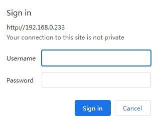
4. Start a browser on the PC, enter http://192.168.0.233 in the address bar, and press Enter. The Web login page opens. 192.168.0.233 represents the default management IP address of the switch, which can be edited after login.
5. As shown in Figure3-2, enter the default administrator username admin and password admin, and then click Sign in. As a best practice, change the login password immediately after the first successful login for security purposes.
4 Maintenance and troubleshooting
Power supply failure
To identify a power failure on the switch, examine the power supply status LEDs on the switch.
Table4-1 Power failure indication of the power supply status LEDs
|
Switch model |
Power input type |
LED mark |
LED status |
Description |
|
IE4300U-5E IE4300U-8E IE4300U-10P IE4300U-10P-PWR |
DC input |
PWR1/PWR2 |
Off |
DC power input failure |
Symptom
A power supply status LED is off.
Solution
To resolve the issue:
1. Verify that the power cord is connectedly correctly.
2. Verify that the power receptacle on the switch is in good condition.
3. Verify that the power outlet is in good condition.
4. Verify that the external power system is operating correctly.
5. Verify that the operating temperature of the switch is in an acceptable range, and adequate ventilation is provided for the switch.
Overtemperature can cause the power supply to stop working and enter self-protection mode.
6. If the issue persists, contact H3C Support.
5 Technical specifications
Table5-1 Technical specifications for the non-PoE switch models
|
Item |
IE4300U-5E |
IE4300U-8E |
IE4300U-10P |
|
Dimensions (H × W × D) |
30 × 120 × 100 mm (1.18 × 4.72 × 3.94 in) |
44 × 150 × 131 mm (1.73 × 5.91 × 5.16 in) |
44 × 150 × 131 mm (1.73 × 5.91 × 5.16 in) |
|
Weight |
≤ 0.36 kg (0.79 lb) |
≤ 0.57 kg (1.26 lb) |
≤ 0.62 kg (1.37 lb) |
|
10/100/1000BASE-T autosensing Ethernet port |
5 |
8 |
8 |
|
SFP port |
N/A |
N/A |
2 × 100/1000BASE-X SFP ports |
|
Input voltage |
DC: · Rated voltage range: 12 to 48 VDC, 0.4 A · Max voltage range: 12 to 60 VDC |
DC: · Rated voltage range: 12 to 48 VDC, 0.5 A · Max voltage range: 12 to 60 VDC |
DC: · Rated voltage range: 12 to 48 VDC, 0.6 A · Max voltage range: 12 to 60 VDC |
|
Power consumption (static) |
Dual DC inputs: 0.84 W |
Dual DC inputs: 1.08 W |
Dual DC inputs: 1.44 W |
|
Power consumption (typical) |
Dual DC inputs: 2.64 W |
Dual DC inputs: 3.00 W |
Dual DC inputs: 3.48 W |
|
Power consumption (full load) |
Dual DC inputs: 2.88 W |
Dual DC inputs: 3.36 W |
Dual DC inputs: 6.48 W |
|
Melting current of power supply fuse |
5 A/125 V |
||
|
Heat dissipation |
Fanless, passive cooling |
||
|
Operating temperature |
–40°C to +70°C (–40°F to +158°F) |
||
|
Operating humidity |
5% RH to 95% RH, noncondensing |
||
|
Ingress protection rating |
IP41 |
||
|
Safety compliance |
UL62368-1/EN62368-1/IEC62368-1/GB4943.1 |
||
Table5-2 Technical specifications for the PoE switch models
|
Item |
IE4300U-10P-PWR |
|
Dimensions (H × W × D) |
44 × 150 × 131 mm (1.73 × 5.91 × 5.16 in) |
|
Weight |
≤ 0.65 kg (1.43 lb) |
|
10/100/1000BASE-T autosensing Ethernet port |
8 (Support for PoE+ power supply) |
|
SFP port |
2 × 100/1000BASE-X SFP ports |
|
Input voltage |
DC: · Rated voltage range: 54 to 57 VDC, 2.8 A · Max voltage range: 24 to 57 VDC |
|
Max PoE power per port |
PoE+ ports 1 to 8: 30 W |
|
Total PoE power |
100 W |
|
Power consumption (static) |
Dual DC inputs: 1.30 W |
|
Power consumption (typical) |
Dual DC inputs: 3.60 W |
|
Power consumption (full load) |
Dual DC inputs: 5.88 W |
|
Melting current of power supply fuse |
5 A/125 V |
|
Heat dissipation |
Fanless, passive cooling |
|
Operating temperature |
–40°C to +70°C (–40°F to +158°F) |
|
Operating humidity |
5% RH to 95% RH, noncondensing |
|
Ingress protection rating |
IP41 |
|
Safety compliance |
UL62368-1/EN62368-1/IEC62368-1/GB4943.1 |
6 Chassis views
The switch provides a reset button used for rebooting or resetting the switch.
· To reboot the switch, press and hold the reset button for no more than 5 seconds.
· To reset the switch, press and hold the reset button for more than 5 seconds. The switch will be restored to the factory defaults.
When you are using the reset button to reboot or reset the switch, the RUN LED on the switch flashes.
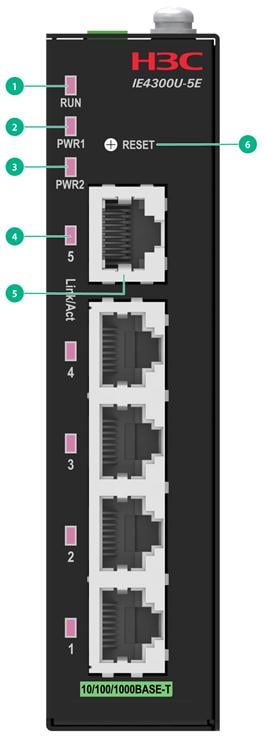
IE4300U-5E
|
(1) Status LED |
(2) Power supply status LED 1 |
|
(3) Power supply status LED 2 |
(4) 10/100/1000BASE-T autosensing Ethernet port LED |
|
(5) 10/100/1000BASE-T autosensing Ethernet port |
(6) Reset button (RESET) |
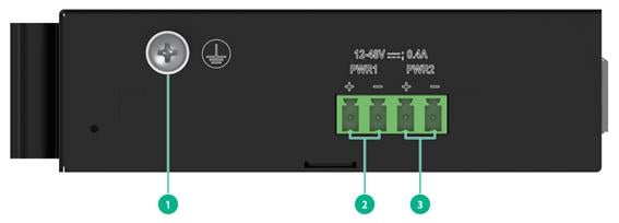
Figure6-2 Top panel
|
(1) Grounding screw |
(2) DC power receptacle 1 (PWR1) |
|
(3) DC power receptacle 2 (PWR2) |
|
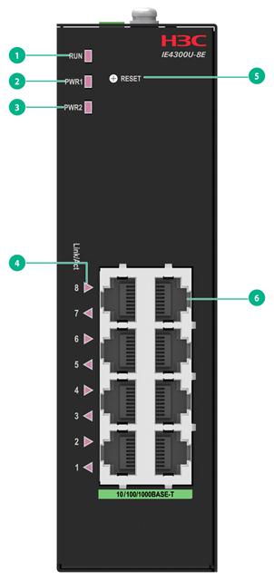
IE4300U-8E
Figure6-3 Front panel
|
(1) Status LED |
(2) Power supply status LED 1 |
|
(3) Power supply status LED 2 |
(4) 10/100/1000BASE-T autosensing Ethernet port LED |
|
(5) Reset button (RESET) |
(6) 10/100/1000BASE-T autosensing Ethernet port |
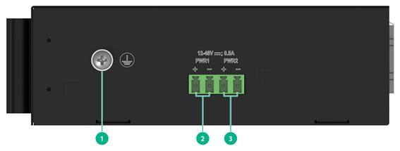
Figure6-4 Top panel
|
(1) Grounding screw |
(2) DC power receptacle 1 (PWR1) |
|
(3) DC power receptacle 2 (PWR2) |
|
IE4300U-10P
Figure6-5 Front panel
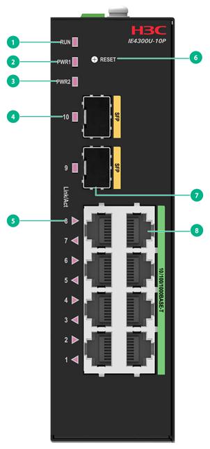
|
(1) Status LED |
(2) Power supply status LED 1 |
|
(3) Power supply status LED 2 |
(4) SFP port LED |
|
(5) 10/100/1000BASE-T autosensing Ethernet port LED |
(6) Reset button (RESET) |
|
(7) SFP port |
(8) 10/100/1000BASE-T autosensing Ethernet port |
Figure6-6 Top panel

|
(1) Grounding screw |
(2) DC power receptacle 1 (PWR1) |
|
(3) DC power receptacle 2 (PWR2) |
|
IE4300U-10P-PWR
Figure6-7 Front panel
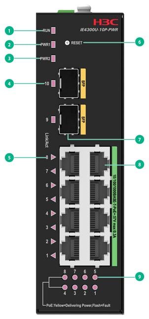
|
(1) Status LED |
(2) Power supply status LED 1 |
|
(3) Power supply status LED 1 |
(4) SFP port LED |
|
(5) 10/100/1000BASE-T autosensing Ethernet port LED |
(6) Reset button (RESET) |
|
(7) SFP port |
(8) 10/100/1000BASE-T autosensing Ethernet port |
|
(9) PoE status LED |
|
Figure6-8 Top panel
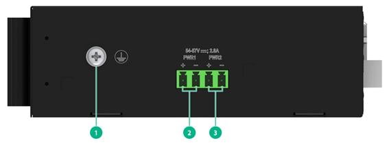
|
(1) Grounding screw |
(2) DC power receptacle 1 (PWR1) |
|
(3) DC power receptacle 2 (PWR2) |
|
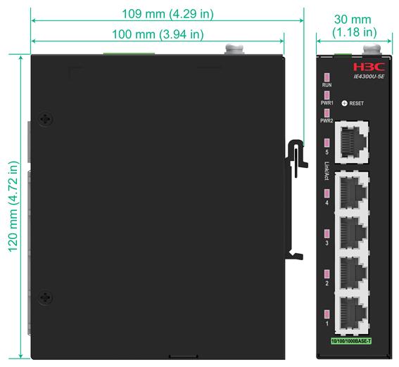
7 Chassis dimensions
Select an appropriate installation position for the switch based on its dimensions.
The following switch models have the same dimensions: IE4300U-8E, IE4300U-10P, and IE4300U-10P-PWR. This section uses the IE4300U-8E switch as an example.
Figure7-1 IE4300U-8E switch dimensions
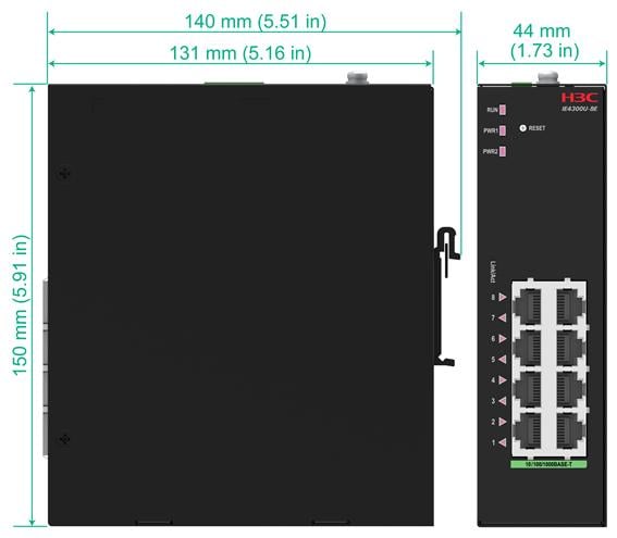
Figure7-2 IE4300U-5E switch dimensions
8 Ports and LEDs
Ports
SFP port
Table8-1 SFP port specifications
|
Item |
Description |
|
Port type |
SFP |
|
Available transceiver modules and cables |
FE SFP transceiver modules described in Table8-2. GE SFP transceiver modules described in Table8-3. |
Table8-2 FE SFP transceiver modules available for the SFP ports
|
Transceiver module model |
Industrial transceiver module |
Central wavelength (nm) |
Connector type |
Cable type and diameter (µm) |
Max transmission distance |
|
SFP-FE-SX-MM1310-A |
No |
1310 |
LC |
50/125, MMF |
2 km (1.24 miles) |
|
62.5/125, MMF |
|||||
|
SFP-FE-LX-SM1310-A |
No |
1310 |
LC |
9/125, SMF |
15 km (9.32 miles) |
|
SFP-FE-LX-SM1310-D |
No |
1310 |
LC |
9/125, SMF |
15 km (9.32 miles) |
|
SFP-FE-LH40-SM1310 |
No |
1310 |
LC |
9/125, SMF |
40 km (24.86 miles) |
|
SFP-FE-LH80-SM1550 |
No |
1550 |
LC |
9/125, SMF |
80 km (49.71 miles) |
|
SFP-FE-BX15-U-SM1310 |
Yes |
1310 |
LC |
9/125, SMF |
15 km (9.32 miles) |
|
SFP-FE-LH40-SM1310-I |
Yes |
1310 |
LC |
9/125, SMF |
40 km (24.86 miles) |
|
SFP-FE-LH80-SM1550-I |
Yes |
1550 |
LC |
9/125, SMF |
80 km (49.71 miles) |
Table8-3 GE SFP transceiver modules available for the SFP ports
|
Transceiver module model |
Industrial transceiver module |
Central wavelength (nm) |
Connector type |
Cable type and diameter (µm) |
Mode bandwidth (MHz*km) |
Max transmission distance |
|
SFP-GE-SX-MM850-A |
No |
850 |
LC |
50/125, MMF |
500 |
550 m (1804.46 ft) |
|
400 |
500 m (1640.42 ft) |
|||||
|
62.5/125, MMF |
200 |
275 m (902.23 ft) |
||||
|
160 |
220 m (721.78 ft) |
|||||
|
SFP-GE-SX-MM850-D |
No |
850 |
LC |
50/125, MMF |
500 |
550 m (1804.46 ft) |
|
400 |
500 m (1640.42 ft) |
|||||
|
62.5/125, MMF |
200 |
275 m (902.23 ft) |
||||
|
160 |
220 m (721.78 ft) |
|||||
|
SFP-GE-SX-MM850-S |
No |
850 |
LC |
50/125, MMF |
500 |
550 m (1804.46 ft) |
|
400 |
500 m (1640.42 ft) |
|||||
|
62.5/125, MMF |
200 |
275 m (902.23 ft) |
||||
|
160 |
220 m (721.78 ft) |
|||||
|
SFP-GE-LX-SM1310-A |
No |
1310 |
LC |
9/125, SMF |
N/A |
10 km (6.21 miles) |
|
50/125, MMF |
500/400 |
550 m (1804.46 ft) |
||||
|
62.5/125, MMF |
500 |
550 m (1804.46 ft) |
||||
|
SFP-GE-LX-SM1310-D |
No |
1310 |
LC |
9/125, SMF |
N/A |
10 km (6.21 miles) |
|
SFP-GE-LH40-SM1310 |
No |
1310 |
LC |
9/125, SMF |
N/A |
40 km (24.86 miles) |
|
SFP-GE-LH40-SM1310-D |
No |
1310 |
LC |
9/125, SMF |
N/A |
40 km (24.86 miles) |
|
SFP-GE-LH40-SM1310-S |
No |
1310 |
LC |
9/125, SMF |
N/A |
40 km (24.86 miles) |
|
SFP-GE-LH40-SM1550 |
No |
1550 |
LC |
9/125, SMF |
N/A |
40 km (24.86 miles) |
|
SFP-GE-LH80-SM1550 |
No |
1550 |
LC |
9/125, SMF |
N/A |
80 km (49.71 miles) |
|
SFP-GE-LH80-SM1550-D |
No |
1550 |
LC |
9/125, SMF |
N/A |
80 km (49.71 miles) |
|
SFP-GE-LH100-SM1550 |
No |
1550 |
LC |
9/125, SMF |
N/A |
100 km (62.14 miles) |
|
SFP-GE-LX-SM1310-BIDI |
No |
Tx: 1310 Rx: 1490 |
LC |
9/125, SMF |
N/A |
10 km (6.21 miles) |
|
SFP-GE-LX-SM1310-BIDI-S |
No |
Tx: 1310 Rx: 1490 |
LC |
9/125, SMF |
N/A |
10 km (6.21 miles) |
|
SFP-GE-LX-SM1310-BIDI-I |
Yes |
Tx: 1310 Rx: 1490 |
LC |
9/125, SMF |
N/A |
10 km (6.21 miles) |
|
SFP-GE-LX-SM1490-BIDI |
No |
Tx: 1490 Rx: 1310 |
LC |
9/125, SMF |
N/A |
10 km (6.21 miles) |
|
SFP-GE-LX-SM1490-BIDI-S |
No |
Tx: 1490 Rx: 1310 |
LC |
9/125, SMF |
N/A |
10 km (6.21 miles) |
|
SFP-GE-LX-SM1490-BIDI-I |
Yes |
Tx: 1490 Rx: 1310 |
LC |
9/125, SMF |
N/A |
10 km (6.21 miles) |
|
SFP-GE-LX10-SM1310 |
Yes |
1310 |
LC |
9/125, SMF |
N/A |
10 km (6.21 miles) |
|
SFP-GE-LH40-SM1310-BIDI |
No |
Tx: 1310 Rx: 1550 |
LC |
9/125, SMF |
N/A |
40 km (24.86 miles) |
|
SFP-GE-LH40-SM1550-BIDI |
No |
Tx: 1550 Rx: 1310 |
LC |
9/125, SMF |
N/A |
40 km (24.86 miles) |
|
SFP-GE-LH70-SM1490-BIDI |
No |
Tx: 1490 Rx: 1550 |
LC |
9/125, SMF |
N/A |
70 km (43.50 miles) |
|
SFP-GE-LH70-SM1550-BIDI |
No |
Tx: 1550 Rx: 1490 |
LC |
9/125, SMF |
N/A |
70 km (43.50 miles) |
|
SFP-GE-LH40-SM1310-I |
Yes |
1310 |
LC |
9/125, SMF |
N/A |
40 km (24.86 miles) |
|
SFP-GE-LH20-SM1310-I |
Yes |
1310 |
LC |
9/125, SMF |
N/A |
20 km (12.43 miles) |
|
SFP-GE-SX-MM850-I |
Yes |
850 |
LC |
50/125, MMF |
500 |
550 m (1804.46 ft) |
|
400 |
500 m (1640.42 ft) |
|||||
|
62.5/125, MMF |
200 |
275 m (902.23 ft) |
||||
|
160 |
220 m (721.78 ft) |
|||||
|
SFP-GE-LH40-SM1310-BIDI-I |
Yes |
Tx: 1310 Rx: 1490 |
LC |
9/125, SMF |
N/A |
40 km (24.86 miles) |
|
SFP-GE-LH40-SM1490-BIDI-I |
Yes |
Tx: 1490 Rx: 1310 |
LC |
9/125, SMF |
N/A |
40 km (24.86 miles) |
|
SFP-GE-LH20-SM1490-BIDI-I |
Yes |
Tx: 1490 Rx: 1310 |
LC |
9/125, SMF |
N/A |
20 km (12.43 miles) |
|
SFP-GE-LH20-SM1310-BIDI-I |
Yes |
Tx: 1310 Rx: 1490 |
LC |
9/125, SMF |
N/A |
20 km (12.43 miles) |
|
SFP-GE-LH80-SM1550-I |
Yes |
1550 |
LC |
9/125, SMF |
N/A |
20 km (12.43 miles) |
|
|
NOTE: · As a best practice, use H3C transceiver modules and cables for the switch. · The H3C transceiver modules and network cables are subject to change over time. For the most recent list of H3C transceiver modules and cables, contact H3C Support or marketing staff. · For the specifications of H3C transceiver modules and network cables, see H3C Transceiver Modules User Guide. · BIDI transceiver modules use different central wavelengths in transmit and receive directions, in order to implement bidirectional transmission of optical signals over the same fiber. · You must use two BIDI transceiver modules in pairs. For example, if one end uses the SFP-GE-LX-SM1310-BIDI transceiver module, the peer end must use the SFP-GE-LX-SM1490-BIDI transceiver module. · Industrial transceiver modules can be used in an environment with a temperature in the range of –40°C to +85°C (–40°F to +185°F). They are more applicable to special industrial scenarios. |
10/100/1000BASE-T Ethernet port
Table8-4 10/100/1000BASE-T Ethernet port specifications
|
Item |
Description |
|
Connector type |
RJ-45 |
|
Rate, duplex mode, and auto-MDI/MDI-X |
· 10 Mbps, half/full duplex · 100 Mbps, half/full duplex · 1000 Mbps, full duplex · MDI/MDI-X autosensing |
|
Max transmission distance |
100 m (328.08 ft) |
|
Transmission medium |
Category 5 or above twisted pair cable |
|
Compliant standard |
IEEE 802.3i, 802.3u, 802.3ab |
LEDs
Fixed power supply status LED
The power supply status LEDs on the front panel of the switch indicate the power supply operating status.
Table8-5 Power supply status LED description
|
Switch model |
LED mark |
Status |
Description |
|
IE4300U-5E IE4300U-8E IE4300U-10P IE4300U-10P-PWR |
PWR1/PWR2 |
Steady green |
Normal DC power input. |
|
Off |
Abnormal or no DC power input. |
Status LED
The switch provides a status LED on the front panel to indicate the operating status of the switch.
Table8-6 Status LED description
|
LED mark |
Status |
Description |
|
RUN |
Steady green |
The switch is operating correctly. |
|
Flashing green |
You are using the reset button to reboot or reset the switch. |
|
|
Off |
The switch has passed the power-on self test (POST) and is operating correctly. |
10/100/1000BASE-T autosensing Ethernet port LED
Table8-7 10/100/1000BASE-T autosensing Ethernet port LED description
|
LED status |
Description |
|
Steady green |
A link is present on the port. |
|
Flashing green |
The port is receiving or sending data. |
|
Off |
No link is present on the port. |
SFP port LED
Table8-8 SFP port LED description
|
LED status |
Description |
|
Steady green |
A link is present on the port. |
|
Flashing green |
The port is receiving or sending data. |
|
Off |
No link is present on the port. |
PoE status LED
Only the IE4300U-10P-PWR switches provide PoE status LEDs to indicate the PoE status of the Ethernet ports.
Table8-9 PoE status LED description
|
LED mark |
Status |
Description |
|
PoE |
Steady yellow |
PoE has been enabled on the Ethernet port. |
|
Off |
PoE is disabled on the Ethernet port. |
