- Table of Contents
- Related Documents
-
| Title | Size | Download |
|---|---|---|
| 01-Text | 25.63 MB |
1 Preparation for installation
Examining the installation environment
Checking power distribution or power supply environment
Mounting the switch on a DIN rail
Mounting the switch on a DIN rail
Grounding the switch by using a grounding strip
Grounding the switch by using a grounding conductor buried in the earth ground
Verifying the connection after grounding the switch
Connecting cables to the alarm input and alarm output connections and RS485 ports
Connecting cables to the alarm input and alarm output connections on an AC switch
Connecting cables to the alarm input and alarm output connections and RS485 ports on a DC switch
Connecting the AC power cord for an AC power supply
Connecting the DC power cord for a DC power supply
3 Accessing the switch for the first time
Connecting the switch to a configuration terminal
4 Maintenance and troubleshooting
10/100/1000BASE-T autosensing Ethernet port LED
8 Available transceiver modules and cables
1 Preparation for installation
|
|
CAUTION: If the switch is used in a manner not specified by the manufacturer, the protection provided by the switch might be impaired. |
This document applies to the following industrial switch models:
Table1-1 Switch models
|
Switch series |
Model |
Product code (PID) |
|
IE4320-EI switch series |
IE4320-8T2P2X-PWR-EI |
LS-IE4320-8T2P2X-PWR-EI-DC |
|
IE4320-8T2P2X-EI |
LS-IE4320-8T2P2X-EI-AC |
|
|
LS-IE4320-8T2P2X-EI-DC |
||
|
IE4320-16T4X-EI |
LS-IE4320-16T4X-EI-DC |
|
|
IE4320-8T8P4X-EI |
LS-IE4320-8T8P4X-EI-DC |
Safety recommendations
|
|
WARNING! When the ambient temperature exceeds 60°C (140°F), the outer surface temperature of the switch might exceed 70°C (158°F). You must install the switch in a restricted access area. To avoid burns, take protective measures when you work with the switch. |
To avoid bodily injury or damage to the switch, read the following safety recommendations carefully before working with the switch. Note that the recommendations do not cover every possible hazardous condition.
· Before cleaning the switch, remove all power cords from the switch. Do not clean the switch with wet cloth or liquid.
· Do not place the switch near water or in a damp environment. Prevent water or moisture from entering the switch chassis.
· Do not place the switch on an unstable case or desk.
· Ensure adequate ventilation for the switch and keep the protective vent of the switch unblocked.
· Make sure the power source voltage meets the requirements of the switch.
· To avoid electrical shocks, do not open the chassis while the switch is operating. As a best practice, do not open the chassis even if the switch is powered off.
· When installing the switch, always wear an ESD wrist strap. Make sure the wrist strap makes good skin contact and is reliably grounded.
|
|
NOTE: The switch is a class A device and might cause radio interference in a residential area. Take adequate measures as required. |
Examining the installation environment
To ensure correct operation of your switch, make sure the installation environment meets the requirements listed in Table1-2.
Table1-2 Checking list for the installation environment
|
Item |
Requirements |
|
Ventilation and heat dissipation |
To ensure correct operation of your device, make sure the installation environment is adequately ventilated to prevent the switch from overheating. · Ensure a minimum clearance of 10 cm (3.94 in) around the chassis. · Do not install the device near a heat source, for example, a stove or heater. · Ensure air ventilation in the installation environment. · Do not block the ventilation holes in the device or power adapter. |
|
Anti-moisture |
Water or moisture might damage the circuits of the device. · Do not place the device near water or in a damp environment. · Install the switch in a clean, dry, and ventilated place where temperature is controlled in a stable range. · Make sure the installation environment is free from water leakage or condensation. If required, install a dehumidification device (such as an air conditioner with a dehumidification function or a dedicated dehumidifier). · Do not operate the device under or near the water source, such as the wash basin, laundry room, or areas with high humidity. · Do not touch the device with wet hands. |
|
Lightning protection |
Ground the switch correctly and verify the grounding. · If you ground the switch by using a grounding strip, make sure the grounding resistance of the grounding strip in the equipment room is less than 1 ohm. · If no grounding strip is available and a grounding conductor (such as an angel iron) is buried into the earth, make sure the grounding resistance of the buried grounding conductor is less than 10 ohms. · Route the signal cables along indoor walls. If cables must be routed outdoors, bury the cables in the earth ground, or thread the cables through steel tubes. Install a signal lightning arrester with a nominal discharge current for a corresponding network interface. · Keep the signal cables far from power cords and lightning rod down conductors. · As a best practice, route power cords indoors. If an AC power cord is routed from outdoors, connect the AC power cord first to a power lightning arrester before leading it to the AC power port on the switch. Make sure the power lightning arrester has a nominal discharge current and the total length of the power cord from the power lighting arrester to the power port on the switch is less than 5 m (16.40 ft). · Ground the switch, rack, independent power supplies, and lightning arresters separately. · You must ground optical fibers with reinforcing metal stiffener from outdoors on an optical distribution frame (ODF) or fiber splice enclosure. |
|
Cable routing |
Do not run an Ethernet cable and power cord in parallel. · Route different types of cables separately. · Keep power cords a minimum of 5 cm (1.97 in) away from other cables. |
|
Mechanical environment |
As a best practice, make sure the mechanical class of the environment is not above 4M4 if you install the switch in an outdoor environment. NOTE: 4M represents the mechanical environment condition defined by GB/T 4798.4. It has eight classes. The 4M4 class refers to places impacted by machines, running vehicles, ground blasting or piling. |
|
Dust and water resistance |
If you install the switch in an outdoor environment, make sure the installation and operating environments meet the requirements of IP51 rating protection. |
|
ESD prevention |
· Ground the switch correctly. · To avoid ESD damage to the device or components, always wear an ESD wrist strap when you install or remove the device. · Make sure the wrist strap has good skin contact and is reliably grounded. |
|
Corrosive gas prevention |
The installation site must be free from corrosive gases such as acid gases and alkaline gases. |
|
EMI |
· If AC power is used, use a single-phase three-wire power receptacle with protection earth (PE) to filter interference from the power grid. · Keep the device far away from radio transmitting stations, radar stations, and high-frequency devices. · Use electromagnetic shielding, for example, shielded interface cables, when necessary. |
Checking power distribution or power supply environment
Table1-3 Requirements for power distribution or power supply environment
|
Item |
Requirements |
|
Preparation |
The power supply must be available before you install the switch. |
|
Voltage |
The voltage provided to the switch must be within the operating voltage range. For the operating voltage range, see the hardware information and specifications for the switch. |
|
Power receptacle and cables |
· If the external power supply system provides an AC power outlet, use a country-specific AC power cord. Make sure the PE wire of the AC power supply is grounded reliably. · If the external power supply system provides an AC power outlet, prepare and use a country-specific AC power cord. · The switch is provided with a terminal block for each power receptacle. No power cord is provided with the switch. Prepare compatible copper power wires yourself as required. For information about the wire diameter and connection requirements, see Table2-5. |
Laser safety
|
|
WARNING! The switch is a Class 1 laser device. Disconnected optical fibers or transceiver modules might emit invisible laser light. Do not stare into beams or view directly with optical instruments when the switch is operating. |
Installation tools
No installation tools are provided with the switch. Prepare the following tools yourself:
· Flat-head screwdriver
· Phillips screwdriver
· ESD wrist strap
· Needle-nose pliers
· Diagonal pliers
· Crimping tool
2 Installing the switch
|
|
CAUTION: Keep the tamper-proof seal on a mounting screw on the chassis cover intact, and if you want to open the chassis, contact H3C for permission. Otherwise, H3C shall not be liable for any consequence caused thereby. |
Mounting the switch on a DIN rail
DIN bracket
The switch came with a DIN bracket installed on it.
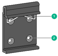
|
(1) Metal spring |
(2) Screw hole |
Table2-1 shows the dimensions of the DIN rails applicable to the DIN bracket. Prepare the DIN rails as required.
Table2-1 Applicable DIN rail dimensions
|
Switch model |
DIN rail dimensions (H × W × D) |
|
IE4320-8T2P2X-PWR-EI-DC IE4320-8T2P2X-EI-AC IE4320-8T2P2X-EI-DC IE4320-16T4X-EI-DC IE4320-8T8P4X-EI-DC |
7.5 × 35 × 1 mm (0.30 × 1.38 × 0.04 in) |

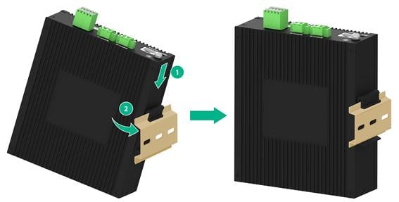
Mounting the switch on a DIN rail
1. Wear an ESD wrist strap and make sure it makes good skin contact and is reliably grounded.
2. As shown by callout 1 in Figure2-3, position the switch so that the spring of the DIN bracket compresses against the upper edge of the DIN rail.
3. As shown by callout 2 in Figure2-3, rotate the switch down toward the DIN rail until the DIN bracket clicks.
Figure2-3 Mounting the switch on a DIN rail (IE4320-8T2P2X-PWR-EI-DC)
Grounding the switch
|
|
WARNING! · Correctly connecting the grounding cable for the switch is crucial to lightning protection, ESD, and EMI protection. · Do not connect the positive pole or negative pole of a DC power receptacle to the ground. To ground the switch, use the grounding cable and grounding screws. · Connect the grounding cable to the grounding strip in the equipment room. Do not connect it to a fire main or lightning rod. |
To protect against the following types of issues, use a grounding cable to connect the switch to the earthing facility at the installation site:
· Bodily injury from electric shocks.
· Device and power and data line damages.
· Electrical fires, lightning strokes, electromagnetic coupling interference, and ESD damages.
Select a grounding method based on the installation environment.
|
|
NOTE: The power and grounding terminals in this section are for illustration only. |
Grounding the switch by using a grounding strip
|
|
CAUTION: To guarantee the grounding effect and avoid switch damage, use the grounding cable provided with the switch to connect the switch to a grounding strip in the equipment room. |
Connecting the grounding cable to the chassis
1. Remove the grounding screw from the grounding hole in the chassis.
2. Attach the grounding screw to the ring terminal of the provided grounding cable.
3. Use a screwdriver to fasten the grounding screw into the grounding screw hole.
Figure2-4 Connecting the grounding cable to the chassis (IE4320-8T2P2X-PWR-EI-DC)
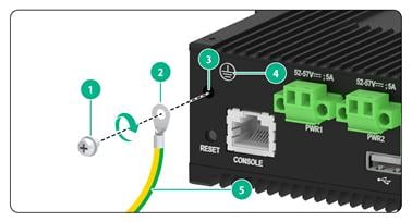
|
(1) Grounding screw |
(2) Ring terminal |
|
(3) Grounding hole |
(4) Grounding sign |
|
(5) Grounding cable |
|
Connecting the grounding cable to a grounding strip
1. Cut the grounding cable to a length according to the distance between the switch and the grounding strip.
2. Peel 20 mm (0.79 in) of insulation sheath by using a wire stripper. Use needle-nose pliers to bend the bare metal part to the shape as shown in Figure2-5. Make sure the bended part can be securely attached to the grounding post on the grounding strip.
3. Attach the bended part of the grounding cable to the grounding post and use the hex nut to fasten the bended part to the post.
Figure2-5 Connecting the grounding cable to a grounding strip

|
(1) Grounding post |
(2) Grounding strip |
|
(3) Grounding cable |
(4) Hex nut |
Grounding the switch by using a grounding conductor buried in the earth ground
If the installation site does not have grounding strips, but earth ground is available, hammer a 2.5 m (8.20 ft) or longer angle iron or steel tube into the earth ground to act as a grounding conductor. Make sure a minimum of 0.7 m (2.30 ft) is left between the top of the grounding conductor and the ground. In cold areas, bury the grounding conductor below the frozen soil layer. In areas with thin soil or rocky gravel, determine the depth for burying the grounding conductor based on the actual condition.
If zinc-coated steel is used, the following dimensions requirements must be met:
· Angle iron—A minimum of 50 × 50 × 5 mm (1.97 × 1.97 × 0.20 in).
· Steel tube—A minimum of 3.5 mm (0.14 in) in thickness.
· Flat steel—A minimum of 40 × 4 mm (1.57 × 0.16 in).
· Round steel—A minimum of 10 mm (0.39 in).
Weld the yellow-green grounding cable to the angel iron or steel tube and treat the joint for corrosion protection.
Figure2-6 Grounding the switch by burying the grounding conductor into the earth ground
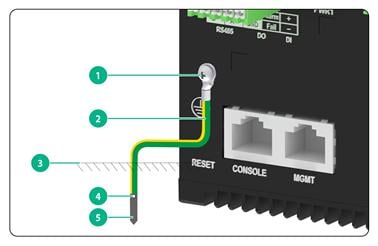
|
(1) Grounding screw |
(2) Grounding cable |
(3) Earth |
|
(4) Joint |
(5) Grounding conductor |
|
Verifying the connection after grounding the switch
Verify the connection after grounding the switch as follows:
· If you ground the switch by using a grounding strip, perform the following tasks:
a. Use a multimeter to measure the resistance between the switch grounding terminal and grounding point, and make sure the resistance is less than 0.1Ω.
b. Use a grounding resistance tester to measure the grounding resistance of the grounding strip, and make sure the grounding resistance is less than 1Ω.
· If you ground the switch by using a grounding conductor buried in the earth ground, perform the following tasks:
a. Use a multimeter to measure the resistance between the switch grounding terminal and grounding point, and make sure the resistance is less than 0.1Ω.
b. Use a grounding resistance tester to measure the grounding resistance of the angle iron in the ground, and make sure the grounding resistance is less than 10Ω.
For locations with high soil resistivity, sprinkle some resistance reducer to reduce soil resistivity or replace soil around the grounding strip with soil with lower resistance.
For information about resistance measurement, see H3C Network Devices Lightning Protection Guide.
Connecting cables to the alarm input and alarm output connections and RS485 ports
|
|
CAUTION: · To avoid connection mistakes, identify the positive (+) and negative (-) marks under the alarm input connection on the switch. · Before you connect cables to the alarm input and alarm output connections, make sure the switch is reliably grounded. |
Use alarm input and alarm output wires to connect the alarm input connection (DI) and alarm output connection (DO), respectively. The RS485 ports are used for industrial control and communication.
The switch came with a terminal block connected to the alarm input and alarm output connections.
No interface cables are provided with the switch. Prepare compatible copper wires yourself as required.
Table2-2 Methods of connecting cables to the alarm input and alarm output connections
|
Switch model |
Method |
|
IE4320-8T2P2X-EI-AC |
Connecting cables to the alarm input and alarm output connections on an AC switch |
|
IE4320-8T2P2X-PWR-EI-DC IE4320-8T2P2X-EI-DC IE4320-16T4X-EI-DC IE4320-8T8P4X-EI-DC |
Connecting cables to the alarm input and alarm output connections and RS485 ports on a DC switch |
Table2-3 Alarm input and alarm output wire specifications
|
Switch model |
Minimum conductor cross-sectional area |
Maximum conductor cross-sectional area |
|
IE4320-EI switch series |
0.08 mm2 or 28 AWG |
0.5 mm2 or 20 AWG |
Connecting cables to the alarm input and alarm output connections on an AC switch
1. As shown by callout 1 in Figure2-7, remove the terminal block.
2. Choose alarm input and alarm output wires based on the installation site requirements.
3. Use a wire stripper to strip the heat-shrink tubes off the wires on one end, and then strip the electrical insulation off to make sure about 7 mm (0.28 in) of the wire reaches out. Repeat this step for the other end.
4. Orient the terminal block with upside up and identify the positive (+) and negative (-) connections on the terminal block.
If you orient the terminal block upside down, you cannot insert it into the alarm input and alarm output connections.
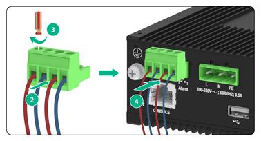
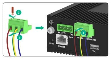
5. As shown by callout 2 in Figure2-8, insert the wires into the terminal block, with the positive wire (red) to the positive connection and negative wire (blue) to the negative connection.
6. Use a flat-head screwdriver to fasten the screws at the top of the terminal block to secure the wires to the terminal block, as shown by callout 3 in Figure2-8.
As a best practice, use a torque of 0.19 Nm (1.7 lb.in) to fasten the screws.
7. Attach the terminal block to the switch, as shown by callout 4 in Figure2-8.
8. Connect the other ends of the wires to external devices.
Figure2-7 Removing the terminal block(IE4320-8T2P2X-EI-AC)
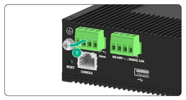
|
|
NOTE: The wire colors in the figure are for illustration only. |
Connecting cables to the alarm input and alarm output connections and RS485 ports on a DC switch
The following uses the IE4320-8T2P2X-PWR-EI-DC switch as an example.
To connect cables to the alarm input and alarm output connections and RS485 ports:
1. As shown by callout 1 in Figure2-9, remove the terminal block.
2. Choose copper wires based on the installation site requirements.
3. Use a wire stripper to strip the heat-shrink tubes off the wires on one end, and then strip the electrical insulation off the wires to make sure about 7 mm (0.28 in) of the wire reaches out. Repeat this step for the other end.
Identify the following marks for correct connections:
¡ A+/B+: Positive differential signal.
¡ A-/B-: Negative differential signal.
¡ COM: Common terminal.
¡ GND: Grounding terminal.
¡ Alarm: Alarm signal terminal.
¡ Fail: Power failure signal terminal.
¡ +: Positive DI signal.
¡ -: Negative DI signal.
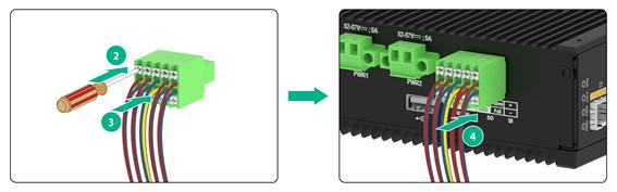
4. As shown by callout 2 in Figure2-10, use a flat-head screwdriver to press down the button on the terminal block.
5. As shown by callout 3 in Figure2-10, insert the wire ends into the terminal block.
6. As shown by callout 4 in Figure2-10, connect the terminal block to the switch.
7. Connect the other ends of the wires to external devices.
Figure2-9 1 Removing the terminal block
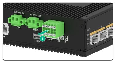
Figure2-10 Connecting cables to the alarm input and alarm output connections on a DC switch
|
|
NOTE: The wire colors in the figure are for illustration only. |
Connecting power cords
Table2-4 Power cord connection procedures at a glance
|
Switch model |
Available power source |
Power cord connection method |
Description |
|
AC power source |
N/A |
||
|
IE4320-8T2P2X-PWR-EI-DC IE4320-8T2P2X-EI-DC IE4320-16T4X-EI-DC IE4320-8T8P4X-EI-DC |
DC power source |
The switch supports dual DC inputs for 1+1 power redundancy. |
Table2-5 Power cord specifications
|
Switch model |
Minimum conductor cross-sectional area |
Maximum conductor cross-sectional area |
|
IE4320-8T2P2X-EI-AC IE4320-8T2P2X-PWR-EI-DC IE4320-8T2P2X-EI-DC IE4320-16T4X-EI-DC IE4320-8T8P4X-EI-DC |
0.5 mm2 or 20 AWG |
3 mm2 or 12 AWG |
Connecting the AC power cord for an AC power supply
|
|
WARNING! · Make sure each power cord has a separate circuit breaker. · Turn off the circuit breaker before connecting the power cord. · To avoid connection mistakes, identify the positive (+) and negative (-) marks under the power receptacle. |
The switch came with a terminal block installed in each AC power receptacle.
Use either of the following methods to connect an AC power cord:
· Connect an AC power cord to an AC power receptacle with a terminal block preinstalled.
· Connect an AC power cord to a terminal block, and then connect the terminal block to an AC power receptacle.
This document uses the second method as an example.
To connect the AC power cord for an AC power supply:
1. Verify that the switch is disconnected from the power source.
2. As shown by callout 1 in Figure2-11, remove the terminal block.
3. Use a wire stripper to strip the heat-shrink tubes off the three-wire power cord on one end, and then strip the electrical insulation off to make sure about 7 mm (0.28 in) of the wire reaches out.
The live wire is in red, neutral wire is in blue, and earth wire is in yellow and green.
4. Orient the terminal block with upside up and identify the "L", "N", and "PE" connections on the terminal block.
If you orient the terminal block upside down, you cannot insert it into the power receptacle.
5. As shown by callout 2 in Figure2-12, insert the AC wires into the terminal block, with the live wire, natural wire, and PE wire inserted into the "L", "N", and "PE" connections, respectively.
6. As shown by callout 3 in Figure2-12, use a flat-head screwdriver to fasten the screws at the top of the terminal block to secure the wires to the connector.
7. As shown by callout 4 in Figure2-12, connect the terminal block to the AC power receptacle.
Figure2-11 Removing the terminal block for an IE4320-8T2P2X-EI-AC switch
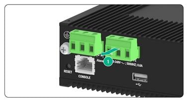
Figure2-12 Connecting the AC power cord for an IE4320-8T2P2X-EI-AC switch
|
|
NOTE: The wire colors in the figure are for illustration only. |
Connecting the DC power cord for a DC power supply
|
|
WARNING! · Make sure each power cord has a separate circuit breaker. · Turn off the circuit breaker before connecting the power cord. · To avoid connection mistakes, identify the positive (+) and negative (-) marks under the DC power receptacle for the terminal block connection and DC power source connection. |
The switch came with a terminal block installed in each DC power receptacle.
Use either of the following methods to connect a DC power cord:
· Connect a DC power cord to a DC power receptacle with a terminal block preinstalled.
· Connect a DC power cord to a terminal block, and then connect the terminal block to a DC power receptacle.
This document uses the second method as an example.
To connect the DC power cord for a DC power supply:
1. Verify that the switch is disconnected from the power source.
2. As shown by callout 1 and 2 in Figure2-13, use a flat-head screwdriver to loosen the screws on the terminal block connected to the alarm input and alarm output connections. Then, remove the terminal block.
3. Use a wire stripper to strip the heat-shrink tubes off the two-wire power cord on one end, and then strip the electrical insulation off to make sure about 7 mm (0.28 in) of the wire reaches out.
4. Orient the terminal block with upside up and identify the positive (+) and negative (-) connections on the terminal block.
If you orient the terminal block upside down, you cannot insert it into the power receptacle.
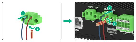
5. As shown by callout 3 in Figure2-14, insert the wires into the terminal block, with the positive wire (red) to the positive connection and negative wire (blue) to the negative connection.
6. As shown by callout 4 in Figure2-14, use a flat-head screwdriver to fasten the screws at the bottom of the terminal block to secure the wires to the terminal block.
7. As shown by callouts 5 and 6 in Figure2-14, connect the terminal block to a DC power receptacle. Use a flat-head screwdriver to fasten the screws on the terminal block to secure the terminal block to the power receptacle.
Figure2-13 Removing the terminal block for an IE4320-8T2P2X-PWR-EI-DC switch
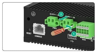
Figure2-14 Connecting the DC power cord for an IE4320-8T2P2X-PWR-EI-DC switch
|
|
NOTE: The wire colors in the figure are for illustration only. |
Verifying the installation
After you complete the installation, verify the following information:
· There is enough space around the switch for heat dissipation.
· The DIN rail is stable.
· The grounding cable is connected correctly.
· The power source is as required by the switch.
· The power cord is correctly connected.
· If part of the network cable for a port is routed outdoors, verify that a network port lightning protector is used for the port.
· If a power line is routed from outdoors, verify that a surge protected power strip is used for the switch.
3 Accessing the switch for the first time
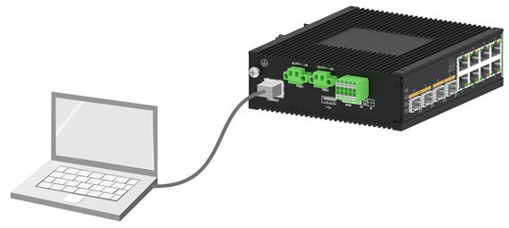
Connecting the switch to a configuration terminal
You can connect the switch to a configuration terminal by using the serial console port.
In Figure3-1, the switch is connected to a configuration terminal (PC as an example) from the serial console port.
Figure3-1 Connecting the switch to a configuration terminal (IE4320-8T8P4X-EI-DC)
As shown in Table3-1, two types of console cables can be used for connecting the switch to a configuration terminal.
Table3-1 Connection methods and console cables
|
Connection method |
Console cable type |
Configuration terminal-side connector |
Switch-side connector |
|
Using the serial console port for connection |
DB9-to-RJ45 console cable |
DB-9 female connector |
RJ-45 |
|
USB-to-RJ45 console cable |
USB port |
RJ-45 |
The switch is not provided with a serial console cable.
The signal pinout for the RJ-45 connector of a serial console cable varies by vendor. To avoid abnormal configuration terminal display, use a serial console cable provided by H3C. For more information, see Table3-2. To prepare a serial console cable yourself, make sure the signal pinout for the RJ-45 connector is the same as that shown in Table3-3.
|
Console cable type |
Console cable view |
Product code for the recommended H3C console cable |
|
DB9-to-RJ45 console cable |
|
04042967 |
|
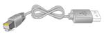
USB-to-RJ45 console cable |
|
0404A1EE |

Connecting the console cable
Connecting a DB9-to-RJ45 console cable
|
|
CAUTION: Follow these guidelines when you connect a DB9-to-RJ45 console cable: · Identify the mark on the console port and make sure you are connecting to the correct port. · The serial ports on PCs do not support hot swapping. To connect a PC to an operating switch, first connect the PC end. To disconnect a PC from an operating switch, first disconnect the switch end. |
A DB9-to-RJ45 serial console cable is an 8-core shielded cable, with a crimped RJ-45 connector at one end for connecting to the serial console port of the switch, and a DB-9 female connector at the other end for connecting to the serial port on a configuration terminal.
Figure3-2 Serial console cable

Table3-3 DB9-to-RJ45 console cable signal pinout
|
RJ-45 |
Signal |
DB-9 |
Signal |
|
1 |
RTS |
8 |
CTS |
|
2 |
DTR |
6 |
DSR |
|
3 |
TXD |
2 |
RXD |
|
4 |
SG |
5 |
SG |
|
5 |
SG |
5 |
SG |
|
6 |
RXD |
3 |
TXD |
|
7 |
DSR |
4 |
DTR |
|
8 |
CTS |
7 |
RTS |
To connect the switch to a configuration terminal (for example, a PC) by using a DB9-to-RJ45 console cable:
1. Plug the DB-9 female connector of the DB9-to-RJ45 console cable to the serial port on the PC.
2. Connect the RJ-45 connector to the serial console port on the switch.
Connecting a USB-to-RJ45 console cable
|
|
IMPORTANT: · To use a USB-to-RJ45 console cable to connect the switch to a configuration terminal, first download and install the USB-to-RJ45 console driver on the configuration terminal and then connect the USB-to-RJ45 console cable to the configuration terminal. · If you have connected a USB-to-RJ45 console cable to the configuration terminal before driver installation, you must reconnect the USB-to-RJ45 console cable to the configuration terminal. |
Figure3-3 USB-to-RJ45 console cable

For information about the signal pinout for the RJ-45 connector of a USB-to-RJ45 console cable, see Table3-3.
The following describes driver installation on the Windows system. To install the driver on other operating systems, see the installation guide in the folder (named according to the operating system type) in the driver compression package.
To connect the device to a configuration terminal by using a USB-to-RJ45 console cable:
1. Click the following link, or copy it to the address bar on your browser and download the USB-to-RJ45 console driver.
http://www.h3c.com/en/home/USB_to_RJ45_Console/
2. View the TXT file Read me in the Windows folder to identify whether the Windows system of the configuration terminal supports the driver.
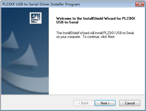
3. If the Windows system supports the driver, install PL23XX-M_LogoDriver_Setup_v200_20190815.exe.
4. Click Next on the welcome page of the driver installation wizard.
Figure3-4 Driver installation wizard
5. Click Finish after the driver installation is completed.
Figure3-5 Driver installation finished

6. Connect the standard USB connector of the cable to the USB port of the configuration terminal.
7. Connect the RJ-45 connector of the cable to the console port on the switch.
Setting terminal parameters
To configure and manage the switch through the console port, you must run a terminal emulator program, such as TeraTermPro, on your configuration terminal. You can use the emulator program to connect a network device, a Telnet site, or an SSH site. For more information about the terminal emulator programs, see the user guides for these programs.
Turn on the PC. On the PC, launch the terminal emulation program and configure the port properties. Configure the terminal parameters as follows:
· Baud rate—9600.
· Data bits—8.
· Stop bits—1.
· Parity—None.
· Flow control—None.
Starting the switch
Pre-startup checklist
Before powering on the switch, verify that the following conditions are met:
· The power cord is correctly connected.
· The power source voltage is as required by the switch.
· The console cable is correctly connected.
· The configuration terminal (a PC, for example) has started, and the terminal parameters have been set correctly.
Powering on the switch
During the startup process, you can access Boot ROM menus to perform tasks such as software upgrade and file management. The Boot ROM interface and menu options vary by software version. For more information about Boot ROM menu options, see the software-matching release notes for the switch.
After the startup completes, you can access the CLI to configure the switch. For more information about the configuration commands and CLI, see the configuration guides and command references for the switch.
4 Maintenance and troubleshooting
Power failure
To identify whether a power failure is present on a .switch, examine the power status LEDs on the switch.
Table4-1 Power failure indication of the power status LEDs
|
Switch model |
Power supply mode |
LED status |
Description |
|
IE4320-8T2P2X-EI-AC |
AC input |
PWR LED: Off |
AC power input failure. |
|
IE4320-8T2P2X-PWR-EI-DC IE4320-8T2P2X-EI-DC IE4320-16T4X-EI-DC IE4320-8T8P4X-EI-DC |
DC input |
PWR1/PWR2 LED: Off |
DC power input failure. |
To resolve the issue:
· Verify that the power cord is connectedly correctly.
· Verify that the power receptacle on the switch is in good condition.
· Verify that the power socket is in good condition.
· Verify that the external power system is operating correctly.
· Verify that the operating temperature of the switch is in an acceptable range, and adequate ventilation is provided for the switch.
Overtemperature can cause the power supply to stop working and enter self-protection mode.
· If the issue persists, contact H3C Support.
5 Technical specifications
Table5-1 Technical specifications for the IE4320-EI non-PoE industrial switch models
|
Item |
IE4320-8T2P2X-EI-AC |
IE4320-8T2P2X-EI-DC |
IE4320-16T4X-EI-DC |
IE4320-8T8P4X-EI-DC |
|
Dimensions (H × W × D) |
149.2 × 48.0 × 129.4 mm (5.87 × 1.89 × 5.09 in) |
149.2 × 44.0 × 129.4 mm (5.87 × 1.73 × 5.09 in) |
149.2 × 78.6 × 129.4 mm (5.87 × 3.09 × 5.09 in) |
149.2 × 78.6 × 129.4 mm (5.87 × 3.09 × 5.09 in) |
|
Weight |
≤ 1.2 kg (2.65 lb) |
|||
|
Console port |
1 |
|||
|
10/100/1000BASE-T autosensing Ethernet port |
8 |
8 |
16 |
8 |
|
SFP port |
2 |
2 |
N/A |
8 |
|
SFP+ port |
2 |
2 |
4 |
4 |
|
Alarm input connection |
The system detects exceptions of the connected device based on the input voltage changes on the alarm input connection. · State: ¡ 1: 13 V to 30 V ¡ 0: –30 to +3 V · Max input current: 8 mA |
|||
|
Alarm output connection |
Uses a relay for output, with a current carrying capacity of 1 A @ 250 VAC or 60 W @ 220 VDC The relay outputs alarms by opening or closing the contact. When the switch is faulty or powered off, the FAIL and COM contacts are closed. When the switch is operating correctly, the FAIL and COM contacts are open. By default, when the switch does not have alarm output, the ALM and COM contacts are open. When the switch has alarm output, the ALM and COM contacts are closed. |
|||
|
RS485 port |
N/A |
2 channels |
2 channels |
2 channels |
|
Input voltage |
AC: · Rated voltage range: 100 to 240 VAC, 0.6 A · Max voltage range: 85 to 264 VAC |
DC: · Rated voltage range: 24 to 48 VDC, 0.5 to 1 A · Max voltage range: 18 to 60 VDC |
DC: · Rated voltage range: 24 to 48 VDC, 0.5 to 1 A · Max voltage range: 18 to 60 VDC |
DC: · Rated voltage range: 24 to 48 VDC, 0.5 to 1 A · Max voltage range: 18 to 60 VDC |
|
Power consumption (static) |
4.998 W |
Single DC input: 4.675 W Dual DC inputs: 4.942 W |
Single DC input: 6.363 W Dual DC inputs: 6.726 W |
Single DC input: 7.196 W Dual DC inputs: 7.038 W |
|
Power consumption (typical) |
8.561 W |
Single DC input: 8.681 W Dual DC inputs: 8.384 W |
Single DC input: 13.311 W Dual DC inputs: 12.856 W |
Single DC input: 11.381 W Dual DC inputs: 11.83 W |
|
Power consumption (full configured) |
12.008 W |
Single DC input: 12.736 W Dual DC inputs: 12.916 W |
Single DC input: 17.575 W Dual DC inputs: 17.823 W |
Single DC input: 20.023 W Dual DC inputs: 20.353 W |
|
Melting current of power supply fuse |
6.3 A/250 V |
10 A/86 V |
10 A/86 V |
10 A/86 V |
|
Heat dissipation |
Fanless, passive cooling |
|||
|
Operating temperature |
–40°C to +70°C (–40°F to +158°F) |
|||
|
Operating humidity |
5% RH to 95% RH, noncondensing |
|||
|
Ingress protection rating |
IP51 |
|||
|
Safety compliance |
UL62368-1/EN62368-1/IEC62368-1/UL60950-1/EN60950-1/IEC60950-1/GB4943.1 |
|||
Table5-2 Technical specifications for the IE4320-EI PoE industrial switch models
|
Item |
IE4320-8T2P2X-PWR-EI |
|
Dimensions (H × W × D) |
149.2 × 44.0 × 129.4 mm (5.87 × 1.73 × 5.09 in) |
|
Console port |
1 |
|
10/100/1000BASE-T autosensing Ethernet port |
8 |
|
SFP port |
2 |
|
SFP+ port |
2 |
|
Alarm input connection |
The system detects exceptions of the connected device based on the input voltage changes on the alarm input connection. · State: ¡ 1: 13 V to 30 V ¡ 0: –30 to +3 V · Max input current: 8 mA |
|
Alarm output connection |
Uses a relay for output, with a current carrying capacity of 1 A @ 250 VAC or 60 W @ 220 VDC The relay outputs alarms by opening or closing the contact. When the switch is faulty or powered off, the FAIL and COM contacts are closed. When the switch is operating correctly, the FAIL and COM contacts are open. By default, when the switch does not have alarm output, the ALM and COM contacts are open. When the switch has alarm output, the ALM and COM contacts are closed. |
|
RS485 port |
2 channels |
|
Input voltage |
DC: · Rated voltage range: 54 to 57 VDC, 5 A · Max voltage range: 18 to 57 VDC
For the switch to provide PoE power for other devices, make sure the input voltage is greater than 55 V. |
|
Max PoE power per port |
30 W |
|
Total PoE power |
125 W |
|
Power consumption (static) |
Dual DC inputs: 5.714 W |
|
Power consumption (typical) |
Dual DC inputs: 9.541 W |
|
Power consumption (fully configured) |
Dual DC inputs: 145 W (PoE: 125 W) |
|
Melting current of power supply fuse |
10 A/86 V |
|
Heat dissipation |
Fanless, passive cooling |
|
Operating temperature |
–40°C to +70°C (–40°F to +158°F) |
|
Operating humidity |
5% RH to 95% RH, noncondensing |
|
Ingress protection rating |
IP51 |
|
Safety compliance |
UL62368-1/EN62368-1/IEC62368-1/UL60950-1/EN60950-1/IEC60950-1/GB4943.1 |
6 Chassis views
IE4320-8T2P2X-EI-AC
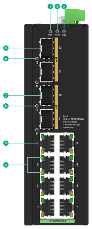
Figure6-1 Front panel
|
(1) Power status LED |
(2) Alarm LED (Alarm) |
|
(3) Diag LED (Diag) |
(4) 10/100/1000BASE-T autosensing Ethernet port LEDs |
|
(5) 10/100/1000BASE-T autosensing Ethernet port |
(6) SFP port LED |
|
(7) SFP port |
(8) SFP+ port LED |
|
(9) SFP+ port |
|
Figure6-2 Top panel

|
(1) Grounding screw |
(2) Alarm input/output connection |
|
(3) AC power receptacle |
(4) USB port |
|
(5) Console port (CONSOLE) |
(6) Reset button (RESET) |
IE4320-8T2P2X-EI-DC
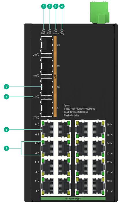
Figure6-3 Front panel

|
(1) Power status LED 1 |
(2) Power status LED 2 |
|
(3) Alarm LED (Alarm) |
(4) Diag LED (Diag) |
|
(5) 10/100/1000BASE-T autosensing Ethernet port LEDs |
(6) 10/100/1000BASE-T autosensing Ethernet port |
|
(7) SFP port LED |
(8) SFP port |
|
(9) SFP+ port LED |
(10) SFP+ port |
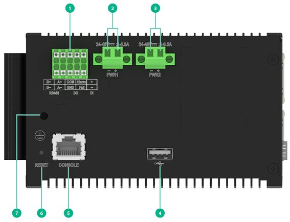
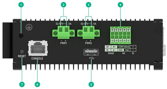
Figure6-4 Top panel

|
(1) Grounding screw |
(2) DC power receptacle 1 |
|
(3) DC power receptacle 2 |
(4) Alarm input/output connection and RS485 ports |
|
(5) USB port |
(6) Console port (CONSOLE) |
|
(7) Reset button (RESET) |
|
IE4320-16T4X-EI-DC
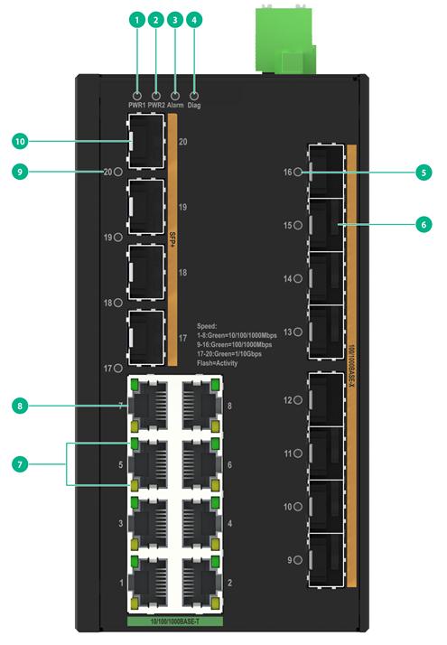
Figure6-5 Front panel
|
(1) Power status LED 1 |
(2) Power status LED 2 |
|
(3) Alarm LED (Alarm) |
(4) Diag LED (Diag) |
|
(5) 10/100/1000BASE-T autosensing Ethernet port LEDs |
(6) 10/100/1000BASE-T autosensing Ethernet port |
|
(7) SFP+ port LED |
(8) SFP+ port |
Figure6-6 Top panel
|
(1) Alarm input/output connection and RS485 ports |
(2) DC power receptacle 1 |
|
(3) DC power receptacle 2 |
(4) USB port |
|
(5) Console port (CONSOLE) |
(6) Reset button (RESET) |
|
(7) Grounding screw |
|
IE4320-8T8P4X-EI-DC
Figure6-7 Front panel
|
(1) Power status LED 1 |
(2) Power status LED 2 |
|
(3) Alarm LED (Alarm) |
(4) Diag LED (Diag) |
|
(5) 100/1000Base-X SFP port LED |
(6) 100/1000Base-X SFP port |
|
(7) 10/100/1000BASE-T autosensing Ethernet port LEDs |
(8) 10/100/1000BASE-T autosensing Ethernet port |
|
(9) SFP+ port LED |
(10) SFP+ port |
Figure6-8 Top panel

|
(1) Alarm input/output connection and RS485 ports |
(2) DC power receptacle 1 |
|
(3) DC power receptacle 2 |
(4) USB port |
|
(5) Console port (CONSOLE) |
(6) Reset button (RESET) |
|
(7) Grounding screw |
|
IE4320-8T2P2X-PWR-EI
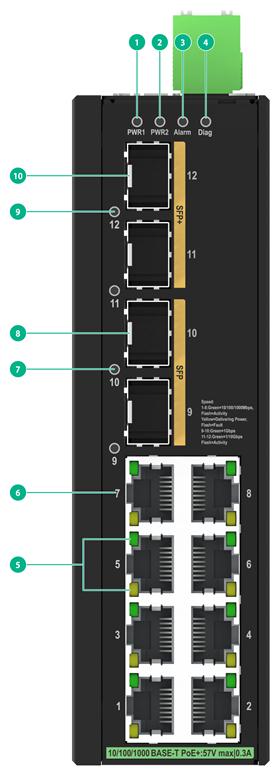
Figure6-9 Front panel
|
(1) Power status LED 1 |
(2) Power status LED 2 |
|
(3) Alarm LED (Alarm) |
(4) Diag LED (Diag) |
|
(5) 10/100/1000BASE-T autosensing Ethernet port LEDs |
(6) 10/100/1000BASE-T autosensing Ethernet port |
|
(7) SFP port LED |
(8) SFP port |
|
(9) SFP+ port LED |
(10) SFP+ port |
Figure6-10 Top panel
|
(1) Grounding screw |
(2) DC power receptacle 1 |
|
(3) DC power receptacle 2 |
(4) Alarm input/output connection and RS485 ports |
|
(5) USB port |
(6) Console port (CONSOLE) |
|
(7) Reset button (RESET) |
|
7 LEDs
Power status LED
The power status LEDs on the front panel indicate the operating status of fixed power supplies.
Table7-1 Power status LED description
|
Switch model |
LED mark |
Status |
Description |
|
IE4320-8T2P2X-EI-AC |
PWR |
Steady green |
Normal AC power input. |
|
Off |
Abnormal or no AC power input. |
||
|
IE4320-8T2P2X-PWR-EI-DC IE4320-8T2P2X-EI-DC IE4320-16T4X-EI-DC IE4320-8T8P4X-EI-DC |
PWR1/PWR2 |
Steady green |
Normal DC power input. |
|
Off |
Abnormal or no DC power input. |
Alarm LED
The alarm LED indicates the result of the digital input voltage change detection or switch internal detection.
Table7-2 Alarm LED description
|
LED mark |
Status |
Description |
|
ALARM |
Steady red |
A digital input exception or internal switch exception has been detected. |
|
Off |
The switch is operating correctly. |
Diag LED
The switch provides a Diag LED on the front panel to indicate the system operating status.
Table7-3 Diag LED description
|
LED mark |
Status |
Description |
|
Diag |
Steady green |
The switch has started up normally. |
|
Flashing green (1Hz) |
The system is performing a power-on self-test or downloading software. |
|
|
Steady red |
Power-on self-test failed or a critical fault has been detected. |
|
|
Off |
The switch is powered off. |
10/100/1000BASE-T autosensing Ethernet port LED
Table7-4 10/100/1000BASE-T autosensing Ethernet port LED description for non-PoE switch models
|
Switch model |
LED status |
Description |
|
IE4320-8T2P2X-EI-AC IE4320-8T2P2X-EI-DC IE4320-16T4X-EI-DC IE4320-8T8P4X-EI-DC |
Steady green |
A link is present on the port. |
|
Flashing green |
The port is receiving or sending data. |
|
|
Off |
No link is present on the port. |
Table7-5 10/100/1000BASE-T autosensing Ethernet port LED description for PoE switch models
|
Switch model |
LED status |
Description |
|
IE4320-8T2P2X-PWR-EI-DC |
Green LED: On |
A link is present on the port and the port is operating at 10/100/1000 Mbps. |
|
Green LED: Flashing |
The port is sending or receiving data at 10/100/1000 Mbps. |
|
|
Green LED: Off |
No link is present on the port, or the port is not connected. |
|
|
Yellow LED: On |
The port has been connected to a PD and PoE power supply is normal. |
|
|
Yellow LED: Flashing |
The port has been connected to a PD but PoE power supply is abnormal. |
|
|
Yellow LED: Off |
The port has not been connected to a PD or PoE is not enabled on the port. |
SFP/SFP+ port LED
Table7-6 SFP/SFP+ port LED description
|
Description |
|
|
Steady green |
A link is present on the port. |
|
Flashing green |
The port is receiving or sending data. |
|
Off |
No link is present on the port. |
8 Available transceiver modules and cables
SFP port
Table8-1 Non-industrial transceiver modules available for the SFP ports
|
Transceiver module model |
Central wavelength (nm) |
Connector type |
Cable/Fiber type and diameter (µm) |
Mode bandwidth (MHz*km) |
Transmission distance |
Transmission rate |
|
SFP-GE-SX-MM850-A SFP-GE-SX-MM850-D SFP-GE-SX-MM850-S |
850 |
LC |
50/125, MMF |
500 |
550 m (1804.46 ft) |
1250 Mbps |
|
400 |
500 m (1640.42 ft) |
1250 Mbps |
||||
|
62.5/125, MMF |
200 |
275 m (902.23 ft) |
1250 Mbps |
|||
|
160 |
220 m (721.78 ft) |
1250 Mbps |
||||
|
SFP-GE-LX-SM1310-F |
1310 |
PoDLC |
9/125, SMF |
N/A |
10 km (6.21 miles) |
1250 Mbps |
|
SFP-GE-LX-SM1310-D SFP-GE-LX-SM1310-S |
1310 |
LC |
9/125, SMF |
N/A |
10 km (6.21 miles) |
1250 Mbps |
|
SFP-GE-LX10-SM1310 |
1310 |
LC |
9/125, SMF |
N/A |
10 km (6.21 miles) |
1250 Mbps |
|
SFP-GE-LX-SM1490-BIDI SFP-GE-LX-SM1490-BIDI-S |
Tx: 1490 Rx: 1310 |
LC |
9/125, SMF |
N/A |
10 km (6.21 miles) |
1250 Mbps |
|
SFP-GE-LX-SM1310-BIDI SFP-GE-LX-SM1310-BIDI-S |
Tx: 1310 Rx: 1490 |
LC |
9/125, SMF |
N/A |
10 km (6.21 miles) |
1250 Mbps |
|
SFP-GE-LH40-SM1310-BIDI |
Tx: 1310 Rx: 1550 |
LC |
9/125, SMF |
N/A |
40 km (24.86 miles) |
1250 Mbps |
|
SFP-GE-LH40-SM1550-BIDI |
Tx: 1550 Rx: 1310 |
LC |
9/125, SMF |
N/A |
40 km (24.86 miles) |
1250 Mbps |
|
SFP-FE-SX-MM1310-A |
1310 |
LC |
50/125, MMF |
N/A |
2 km (1.24 miles) |
155 Mbps |
|
62.5/125, MMF |
N/A |
|||||
|
SFP-FE-LX-SM1310-A |
1310 |
LC |
9/125, SMF |
N/A |
15 km (9.32 miles) |
155 Mbps |
|
SFP-FE-LH40-SM1310 |
1310 |
LC |
9/125, SMF |
N/A |
40 km (24.86 miles) |
155 Mbps |
|
SFP-FE-BX15-U-SM1310 |
1310 |
LC |
9/125, SMF |
N/A |
15 km (9.32 miles) |
155 Mbps |
|
SFP-FE-LX-SM1310-BIDI |
Tx: 1310 Rx: 1550 |
LC |
9/125, SMF |
N/A |
15 km (9.32 miles) |
155 Mbps |
|
SFP-FE-LX-SM1550-BIDI |
Tx: 1550 Rx: 1310 |
LC |
9/125, SMF |
N/A |
15 km (9.32 miles) |
155 Mbps |
|
SFP-FE-LH80-SM1550 |
1550 |
LC |
9/125, SMF |
N/A |
80 km (49.71 miles) |
155 Mbps |
Table8-2 Industrial transceiver modules available for the SFP ports
|
Transceiver module model |
Central wavelength (nm) |
Connector type |
Cable/Fiber type and diameter (µm) |
Mode bandwidth (MHz*km) |
Transmission distance |
Transmission rate |
|
SFP-GE-T-I |
N/A |
RJ-45 |
Category 5e twisted pair cable |
N/A |
100 m (328.08 ft) |
1250 Mbps |
|
SFP-FE-LH80-SM1550-I |
1550 |
LC |
9/125, SMF |
N/A |
80 km (49.71 miles) |
155 Mbps |
|
SFP-FE-LH40-SM1310-I |
1310 |
LC |
9/125, SMF |
N/A |
40 km (24.86 miles) |
155 Mbps |
|
SFP-GE-SX-MM850-I |
850 |
LC |
50/125, MMF |
500 |
550 m (1804.46 ft) |
1250 Mbps |
|
400 |
500 m (1640.42 ft) |
|||||
|
62.5/125, MMF |
200 |
275 m (902.23 ft) |
1250 Mbps |
|||
|
160 |
220 m (721.78 ft) |
|||||
|
SFP-GE-LH80-SM1550-I |
1550 |
LC |
9/125, SMF |
N/A |
80 km (49.71 miles) |
1250Mbps |
|
SFP-GE-LX-SM1310-BIDI-I |
Tx: 1310 Rx: 1490 |
LC |
9/125, SMF |
N/A |
10 km (6.21 miles) |
1250 Mbps |
|
SFP-GE-LX-SM1490-BIDI-I |
Tx: 1490 Rx: 1310 |
LC |
9/125, SMF |
N/A |
10 km (6.21 miles) |
1250 Mbps |
|
SFP-GE-LH20-SM1310-BIDI-I |
Tx: 1310 Rx: 1490 |
LC |
9/125, SMF |
N/A |
20 km (12.43 miles) |
1250 Mbps |
|
SFP-GE-LH20-SM1490-BIDI-I |
Tx: 1490 Rx: 1310 |
LC |
9/125, SMF |
N/A |
20 km (12.43 miles) |
1250 Mbps |
|
SFP-GE-LH40-SM1310-BIDI-I |
Tx: 1310 Rx: 1490 |
LC |
9/125, SMF |
N/A |
40 km (24.86 miles) |
1250 Mbps |
|
SFP-GE-LH40-SM1490-BIDI-I |
Tx: 1490 Rx: 1310 |
LC |
9/125, SMF |
N/A |
40 km (24.86 miles) |
1250 Mbps |
|
SFP-GE-LH40-SM1310-I |
1310 |
LC |
9/125, SMF |
N/A |
40 km (24.86 miles) |
1250 Mbps |
|
SFP-GE-LH20-SM1310-I |
1310 |
LC |
9/125, SMF |
N/A |
20 km (12.43 miles) |
1250 Mbps |
|
SFP-2.5G-LX10-SM1310-DR-I |
1310 |
LC |
9/125, SMF |
N/A |
10 km (6.21 miles) |
2.5Gbps |
Table8-3 Non-industrial cables available for the SFP ports
|
Cable model |
Transmission distance |
Transmission rate |
Cable type |
|
SFP-STACK-Kit SFP-STACK-Kit-S |
1.5 m (4.92 ft) |
1250 Mbps |
UTP/STP |
|
|
NOTE: Only the 100/1000Base-X SFP ports of the IE4320-8T8P4X-EI-DC support FE transceiver modules. |
SFP+ port
SFP+ ports support the following transceiver modules and cables:
· GE and 2.5G SFP transceiver modules and cables described in Table8-1, Table8-2, and Table8-3.
· 10GE SFP+ transceiver modules and cables described in Table8-4, Table8-5, and Table8-6.
Table8-4 Non-industrial transceiver modules available for the SFP+ ports
|
Transceiver module model |
Central wavelength (nm) |
Connector type |
Cable/Fiber type and diameter (µm) |
Mode bandwidth (MHz*km) |
Transmission distance |
Transmission rate |
|
SFP-XG-SX-MM850-D SFP-XG-SX-MM850-E SFP-XG-SX-MM850-S SFP-XG-SX-MM850-A |
850 |
LC |
50/125, MMF |
4700 |
400 m (1312.34 ft) |
10.31 Gbps |
|
2000 |
300 m (984.25 ft) |
|||||
|
500 |
82 m (269.03 ft) |
|||||
|
400 |
66 m (216.54 ft) |
|||||
|
62.5/125, MMF |
200 |
33 m (108.27 ft) |
||||
|
160 |
26 m (85.30 ft) |
|||||
|
SFP-XG-LX-SM1310 SFP-XG-LX-SM1310-D SFP-XG-LX-SM1310-E SFP-XG-LX-SM1310-S SFP-XG-LX-SM1310-F |
1310 |
LC |
9/125, SMF |
N/A |
10 km (6.21 miles) |
10.31 Gbps |
|
SFP-XG-CPRI-IR-SM1310 |
1310 |
LC |
9/125, SMF |
N/A |
1.4 km (0.87 miles) |
10.31 Gbps |
|
SFP-XG-SX-MM850-H |
850 |
LC |
50/125, MMF |
4700 |
400 m (1312.34 ft) |
10.31 Gbps |
|
2000 |
300 m (984.25 ft) |
|||||
|
500 |
82 m (269.03 ft) |
|||||
|
400 |
66 m (216.54 ft) |
|||||
|
62.5/125, MMF |
200 |
33 m (108.27 ft) |
||||
|
160 |
26 m (85.30 ft) |
|||||
|
SFP-XG-CPRI-LR-SM1310 |
1310 |
LC |
9/125, SMF |
N/A |
10 km (6.21 miles) |
4.92 to 10.31 Gbps |
|
SFP-XG-LX-SM1270-BIDI SFP-XG-LX-SM1270-BIDI-S |
Tx: 1270 Rx: 1330 |
LC |
9/125, SMF |
N/A |
10 km (6.21 miles) |
10.31 Gbps |
|
SFP-XG-LX-SM1330-BIDI SFP-XG-LX-SM1330-BIDI-S |
Tx: 1330 Rx: 1270 |
LC |
9/125, SMF |
N/A |
10 km (6.21 miles) |
10.31 Gbps |
Table8-5 Industrial transceiver modules available for the SFP+ ports
|
Transceiver module model |
Central wavelength (nm) |
Connector type |
Cable/Fiber type and diameter (µm) |
Mode bandwidth (MHz*km) |
Transmission distance |
Transmission rate |
|
SFP-XG-SX-MM850-I |
850 |
LC |
50/125, MMF |
4700 |
400 m (1312.34 ft) |
10.31 Gbps |
|
2000 |
300 m (984.25 ft) |
|||||
|
500 |
82 m (269.03 ft) |
|||||
|
400 |
66 m (216.54 ft) |
|||||
|
62.5/125, MMF |
200 |
33 m (108.27 ft) |
||||
|
160 |
26 m (85.30 ft) |
|||||
|
SFP-XG-LH40-SM1550-I |
1550 |
LC |
9/125, SMF |
N/A |
40 km (24.86 miles) |
10.31 Gbps |
|
SFP-XG-LX-SM1310-I |
1310 |
LC |
9/125, SMF |
N/A |
10 km (6.21 miles) |
10.31 Gbps |
Table8-6 Non-industrial cables available for the SFP+ ports
|
Cable model |
Cable length |
Transmission rate |
|
LSWM1STK |
0.65 m (2.13 ft) |
10.31 Gbps |
|
LSWM2STK |
1.2 m (3.94 ft) |