- Table of Contents
-
- 14-High Availability Configuration Guide
- 00-Preface
- 01-Ethernet OAM configuration
- 02-CFD configuration
- 03-DLDP configuration
- 04-Monitor Link configuration
- 05-S-Trunk configuration
- 06-Error code detection configuration
- 07-VRRP configuration
- 08-VSRP configuration
- 09-Failover group configuration
- 10-Service instance group configuration
- 11-BFD configuration
- 12-Track configuration
- 13-Process placement configuration
- Related Documents
-
| Title | Size | Download |
|---|---|---|
| 08-VSRP configuration | 1.36 MB |
VSRP control channel fast detection
Restrictions and guidelines: Subinterface configuration consistency
Specifying a virtual IPv6 address
Enabling SNMP notifications for VSRP
Configuring VSRP for BRAS services (IPoE/PPPoE)
Restrictions and guidelines for configuring VSRP for IPoE
Associating a BRAS service-enabled interface with a VSRP instance
Specifying the TCP port number for establishing BRAS service backup data channels
Restrictions and guidelines for configuring VSRP for L2TP
Prerequisites for configuring VSRP for L2TP
Associating an L2TP group with a VSRP instance
Specifying the source address for an L2TP tunnel
Specifying an L2TP tunnel ID range
Specifying the TCP port number for establishing L2TP service backup data channels
Restrictions and guidelines for configuring VSRP for ARP
Specifying the TCP port number for establishing ARP service backup data channels
Restrictions and guidelines for configuring VSRP for ND
Specifying the TCP port number for establishing ND service backup data channels
Configuring VSRP for DHCPv4 server
Associating an IPv4 address pool with a VSRP instance
Associating a client-side interface with a VSRP instance
Specifying the TCP port number for establishing DHCPv4 server service backup data channels
Configuring VSRP for DHCPv6 server
Restrictions and guidelines for configuring VSRP for an IPv6 address pool
Associating an IPv6 address pool with a VSRP instance
Associating a client-side interface with a VSRP instance
Specifying the TCP port number for establishing DHCPv6 server service backup data channels
Configuring VSRP for DHCPv4 relay
About VSRP for DHCPv4 relay agent
Associating a DHCPv4 client-side interface with a VSRP instance
Specifying the TCP port number for establishing DHCPv4 relay service backup data channels
Configuring VSRP for DHCPv6 relay
Associating a DHCPv6 client-side interface with a VSRP instance
Specifying the TCP port number for establishing DHCPv6 relay service backup data channels
Associating an IGMP-enabled interface with a VSRP instance
Enabling VSRP load sharing on an IGMP-enabled interface
Specifying the TCP port number for establishing IGMP service backup data channels
Enabling IGMP data synchronization
Associating an MLD-enabled interface with a VSRP instance
Enabling VSRP load sharing on an MLD-enabled interface
Specifying a TCP port number for establishing MLD service backup data channels
Enabling MLD data synchronization
Display and maintenance commands for VSRP
Example: Configuring VSRP for IPoE (IPv4 address pool)
Example: Configuring VSRP for IPoE (IPv6 address pool)
Example: Configuring VSRP for dual-stack IPoE (IPv4 and IPv6 address pools)
Example: Configuring VSRP for PPPoE (NDRA one prefix per user)
Example: Configuring VSRP for dual-stack PPPoE (IPv4 address pool and NDRA one prefix per user)
Example: Configuring VSRP for L2TP
Example: Configuring VSRP and VRRP collaboration for ARP
Example: Configuring VSRP and S-Trunk collaboration for ARP
Example: Configuring VSRP and VRRP collaboration for ND
Example: Configuring VSRP and S-Trunk collaboration for ND
Example: Configuring VSRP for IGMP
Example: Configuring VSRP load sharing on an IGMP-enabled interface
Example: Configuring VSRP for MLD
Example: Configuring VSRP load sharing on an MLD-enabled interface
Configuring VSRP
About VSRP
Virtual Service Redundancy Protocol (VSRP) provides unified device-level backup for multiple user services between two devices operating in master/backup mode.
When the master and backup devices are operating correctly, VSRP backs up user data of service modules from the master device to the backup device. When the master device or its link fails, the user services can be fast switched to the backup device. When the original master device or its link is recovered, the user services fall back to the original master device to ensure service continuity.
Basic concepts
VSRP includes the following components:
· VSRP group—A VSRP group contains two peer devices that are enabled with VSRP.
· VSRP peer—The member devices in a VSRP group are the peer of each other, with one as master and the other as backup. You must configure the peer IP address on each device to create a VSRP group.
· VSRP instance—A VSRP instance is associated with one service to back up service data from the master to the backup for service continuity.
· VSRP control channel and data channel—The VSRP peers in a VSRP group synchronize VSRP instance state information and service data by establishing TCP control and data channels.
¡ Control channel—The master backs up the status of all VSRP instances on the VSRP group to the backup in real time over the control channel.
¡ Data channel—VSRP establishes a data channel to back up data in real time for each service associated with a VSRP instance on the VSRP group. This backup mechanism ensures that the backup device takes over the services when the master fails.
Both TCP control and data channels are initiated by the peer with lower IP address to the peer with higher IP address.
VSRP operating mechanism
A VSRP group contains two peer devices that are enabled with VSRP. VSRP collaborates with VRRP or S-Trunk to determine the role of each peer device in a VSRP group as master or backup.
VSRP is typically used on a network that contains broadband remote access servers (BRASs). To ensure service continuity, the master BRAS backs up authentication, accounting, and management information to the backup BRAS in real time.
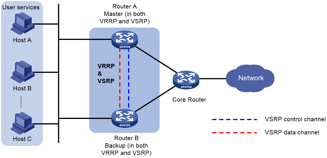
VRRP collaboration
As shown in Figure 1, VSRP determines the roles of the peer devices in the VSRP group in consistent with their roles in the VRRP group. The master forwards traffic and backs up the services to the backup device either at a regular interval or when traffic reaches the specified threshold. When the master in the VSRP group fails, the backup takes over to ensure service continuity. For more information about VRRP, see "Configuring VRRP."
Figure 1 VSRP-VRRP collaboration
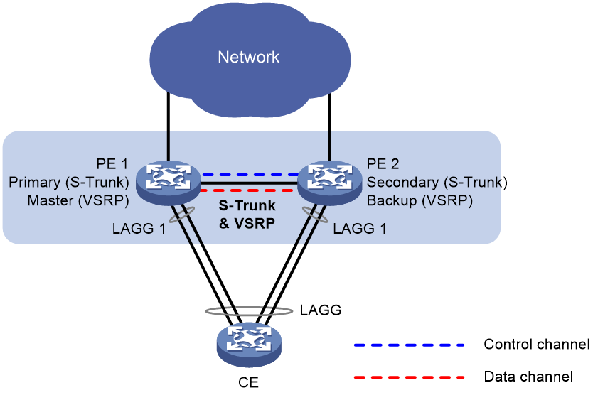
S-Trunk collaboration
To use S-Trunk together with VSRP, you must configure the same smart trunk on the peers in a VSRP group. As shown in Figure 2, VSRP determines the roles of the peer devices in the VSRP group based on their roles in the S-Trunk system. The VSRP master is the primary S-Trunk member device, and the VSRP backup is the secondary S-Trunk member device. The master forwards traffic and backs up the services to the backup device. When the master in the VSRP group fails, the backup takes over to ensure service continuity. For more information about S-Trunk, see "Configuring S-Trunk."
Figure 2 VSRP-S-Trunk collaboration
VSRP backup modes
A VSRP instance supports the following backup modes:
· Hot backup mode (1:1 backup)—The backup device issues backup data to the data plane as soon as it receives the data from the master. In this mode, the backup takes over quickly when the master fails. This mode is applicable to scenarios where a device acts as the backup in only one VSRP group.
VSRP provides the following hot backup modes:
¡ Dual-active hot backup mode—Both the master and backup devices are active to load share traffic. This mode is supported only in the VSRP and S-Trunk collaboration network. Do not configure this mode in other networks.
¡ Single-active hot backup mode—The master device is active to process service traffic, and the backup device takes over when the master device fails.
· Warm backup mode (N:1 backup)—One backup device backs up multiple master devices. The backup device issues received backup data to the data plane when a master fails. This mode has a longer failover delay than hot backup mode. This mode is applicable to scenarios where a device acts as the backup in more than one VSRP group.
VSRP control channel fast detection
By default, a VSRP group detects the state of the failover link based only on the state of the TCP control channel. To fast detect the state of the failover link, you can perform the following tasks:
1. Use NQA or BFD to monitor the state of the failover link.
2. Establish the collaboration between the failover link state and NQA or BFD through the Track function.
A VSRP group operates differently depending on the state of the track entry associated with the VSRP group:
· When the track entry is in Positive or NotReady state, a device attempts to establish a TCP control channel with its peer.
· When the track entry changes to Negative state, the device terminates the TCP control channel.
Restrictions and guidelines: Subinterface configuration consistency
As a best practice to maintain data consistency, make sure the peer devices in a VSRP group have consistent main interface and subinterface configuration, including but not limited to the following settings:
· Subinterface numbers.
· VLAN configuration.
· VPN configuration.
VSRP tasks at a glance
To configure VSRP, perform the following tasks:
2. Configuring a VSRP instance
3. Specifying a virtual IPv6 address
This task is required if you enable VSRP for IPoE or DHCPv6 on an IPv6 network.
4. (Optional.) Enabling VSRP logging
5. (Optional.) Enabling SNMP notifications for VSRP
6. Setting up protection tunnels
1. Configuring VSRP for a service module
¡ Configuring VSRP for BRAS services (IPoE/PPPoE)
¡ Configuring VSRP for DHCPv4 server
¡ Configuring VSRP for DHCPv6 server
¡ Configuring VSRP for DHCPv4 relay
¡ Configuring VSRP for DHCPv6 relay
Prerequisites for VSRP
Perform the following tasks on the two peer devices in a VSRP group:
1. For VSRP to collaborate with VRRP, configure VRRP to operate in standard mode.
2. For VSRP to collaborate with VRRP, configure a VRRP group on the two peer devices to determine their role in the VSRP group.
3. For VSRP to collaborate with S-Trunk, configure a smart trunk on the two peer devices to determine their role in the VSRP group. Make sure the primary and secondary member interfaces of the smart trunk are on the desired VSRP master and backup, respectively.
|
|
NOTE: Binding a VSRP group or smart trunk to an existing VRRP group does not affect the functionality of the VRRP group or smart trunk. |
Configuring a VSRP group
1. Enter system view.
system-view
2. Create a VSRP group and enter the VSRP peer view.
vsrp peer peer-name
3. Configure TCP connection parameters for establishing VSRP channels to the peer.
peer [ ipv6 ] peer-ip-address local local-ip-address [ port port-id ]
By default, no VSRP channels are established to the peer.
The TCP port cannot be in use. To view the TCP port numbers in use, execute the display [ ipv6 ] tcp command.
4. (Optional.) Associate a VSRP group with a track entry.
track track-entry-number
Configuring a VSRP instance
About this task
A VSRP instance backs up data for its associated service.
A VSRP instance can be bound to only one VSRP group. Each VSRP instance on a VSRP group is identified by a unique backup ID.
The master forwards traffic and backs up service data to the backup device at the specified interval or when the specified traffic threshold is reached.
An IPoE or PPPoE network requires an address pool to be created on the master and backup of a VSRP instance and route advertisement for subnets of the address pool. By default, only the master advertises the subnet routes, and network devices reach terminal users only through the master. If the master fails or is disconnected, communication with the terminal users is interrupted before the backup takes over.
You can enable route advertisement for the backup to reduce the service outage. After you configure this feature, the network devices have two routes to reach a terminal user, and the route advertised by the master has a smaller route cost. When both the master and the backup are available, the network devices access terminal users through the master. When the master becomes unavailable, the network devices look up the routing table and use the routes advertised by the backup to reach terminal users.
Restrictions and guidelines
The NAS parameters (IP address, interface, and host name) on a VSRP instance are shared by the VSRP member devices for the associated service. Configure NAS settings on a VSRP instance if its associated service requires the NAS parameters to remain unchanged after a master/backup switchover. For example, the settings are applicable to the following scenarios:
· Avoid re-authentication on master/backup switchover by maintaining the same NAS-IP-address, NAS-Port, and host name in packets sent to the RADIUS server.
· Maintain the same Option 82 values in packets sent to the DHCP server.
Procedure
1. Enter system view.
system-view
2. Create a VSRP instance and enter VSRP instance view.
vsrp instance instance-name
3. Specify a backup ID for the VSRP instance.
backup id backup-id peer peer-name
By default, a VSRP instance has no ID.
4. Configure collaboration of the VSRP instance with a module for VSRP role assignment. Choose one option as needed:
¡ Bind the VSRP instance to a VRRP group. Choose one option as needed:
- Bind the VSRP instance to an IPv4 VRRP group.
bind vrrp vrid virtual-router-id interface interface-type interface-number
By default, a VSRP instance is not bound to an IPv4 VRRP group.
- Bind the VSRP instance to an IPv6 VRRP group.
bind vrrp ipv6 vrid virtual-router-id interface interface-type interface-number
By default, a VSRP instance is not bound to an IPv6 VRRP group.
¡ Bind the VSRP instance to a smart trunk member interface.
bind s-trunk s-trunk-id interface route-aggregation interface-number
By default, a VSRP instance is not bound to any smart trunk member interface.
If you execute the following commands multiple times for a VSRP instance, the most recent configuration takes effect:
¡ bind s-trunk
¡ bind vrrp ipv6 vrid
¡ bind vrrp vrid
5. Set the backup mode of the VSRP instance.
backup mode { hot [ dual-active ] | warm }
By default, a VSRP instance operates in hot backup mode.
The dual-active keyword is supported only in the VSRP and S-Trunk collaboration network. Do not configure this keyword in other networks.
6. (Optional.) Set a traffic backup interval or a traffic threshold that triggers a traffic backup.
traffic backup { interval interval-value | threshold threshold-value } *
By default, a VSRP instance backs up traffic at 10-minute intervals or when the traffic reaches 50 MB.
7. (Optional.) Enable route advertisement for the backup.
backup route-advertise [ master-cost master-cost backup-cost backup-cost ]
By default, route advertisement is enabled only for the master.
8. (Optional.) Configure NAS parameters.
nas { id host-name | ip ip-address | port interface-type interface-number }
By default, no NAS parameters are configured.
Specifying a virtual IPv6 address
About this task
To enable VSRP for IPv6 services (such as IPoE and DHCPv6), you must specify a virtual IPv6 address for the service-enabled interface. This is applicable to some special networks, such as a network that contains BRAS devices. In a VSRP instance, you must configure the same virtual IPv6 address on the master and the backup. Then, the master advertises the virtual IPv6 address as the gateway address in RA messages to the hosts. In this way, traffic from the hosts can be directed to the master.
Procedure
1. Enter system view.
system-view
2. Enter interface view.
interface interface-type interface-number
The following types of interfaces are supported:
¡ Layer 3 Ethernet interface.
¡ Layer 3 Ethernet subinterface.
¡ Layer 3 aggregate interface.
¡ Layer 3 aggregate subinterface.
¡ Layer 3 FlexE logical interface.
3. Specify a virtual IPv6 address for the interface that is associated with a VSRP instance.
ipv6 virtual-address ipv6-address vsrp vsrp-instance
By default, no virtual IPv6 address is specified for the interface.
Enabling VSRP logging
About this task
If logging is enabled for VSRP, a log messages generated after an important event occurs, such as VSRP connection setup, abnormal VSRP connection, or VSRP instance status switchover.
The VSRP logging feature sends log messages to the information center. The information center can then output log messages from different source modules to different destinations. For more information about information center, see Network Management and Monitoring Configuration Guide.
Procedure
1. Enter system view.
system-view
2. Enable VSRP logging.
vsrp log enable
By default, VSRP logging is disabled.
Enabling SNMP notifications for VSRP
About this task
If SNMP notifications are enabled for VSRP, a notification is sent to the SNMP module after an important event occurs, such as VSRP connection setup, abnormal VSRP connection, or VSRP instance status switchover.
For SNMP notifications to be sent correctly, you must also configure SNMP on the device. For more information about SNMP configuration, see Network Management and Monitoring Configuration Guide.
Procedure
1. Enter system view.
system-view
2. Enable SNMP notifications for VSRP.
snmp-agent trap enable vsrp
By default, SNMP notifications are enabled for VSRP.
Setting up protection tunnels
About this task
To ensure service continuity when the access-side link of the master fails, the master forwards the traffic sent from the external network to users towards the backup over a protection tunnel. The backup then forwards the traffic to the destination.
The master and the backup set up protection tunnels for the public instance and each VPN instance. The protection tunnel for the public instance is set up after you finish protection tunnel configuration, while the protection tunnel for a VPN instance is set up on demand.
Restrictions and guidelines
VSRP supports the following LSP and SRv6 protection tunnels:
· SR TE tunnels. For more information, see SR-MPLS TE policy configuration in Segment Routing Configuration Guide.
· SRv6 BE tunnels. For more information, see SRv6 VPN configuration in Segment Routing Configuration Guide.
Procedure
1. Enter system view.
system-view
2. Create a VSRP group and enter VSRP peer view.
vsrp peer peer-name
3. Configure protection tunnels. Choose one of the following methods:
¡ Specify the destination address of LSP protection tunnels.
protect lsp-tunnel for-all-instance peer-ip ip-address [ tunnel-policy policy-name ]
By default, no LSP protection tunnel destination address is configured.
¡ Specify a locator for SRv6 protection tunnels.
protect srv6-tunnel for-all-instance locator locator-name
By default, no SRv6 protection tunnels exist.
Configuring VSRP for BRAS services (IPoE/PPPoE)
About VSRP for BRAS services
To back up BRAS services on an interface, associate that interface with a VSRP instance.
Restrictions and guidelines for configuring VSRP for IPoE
· This feature applies only to IPoE and PPPoE.
· You must associate the peer IPoE-enabled interfaces on the master and the backup with the same VSRP instance.
· If you configure VLAN termination on the subinterfaces on the master and backup, make sure the subinterfaces terminate the same VLAN IDs.
· On a device, you cannot associate multiple interfaces with the same VSRP instance. You can associate subinterfaces of an interface with the same or different VSRP instances.
· On an interface, configuring or removing a VSRP instance association causes all online IPoE and PPPoE users to go offline.
· To modify the VSRP instance association of an interface, first use the undo bras vsrp-instance command to remove the existing VSRP instance association.
· If BRAS users use address pools, you must associate the address pools with the same VSRP instance used by BRAS services.
· For static individual users to access the network, make sure you configure the same static IPoE sessions on the master and backup.
· You must configure the same IP address pool on the master and backup. Make sure the BRAS users obtain the same gateway address after a master and backup switchover.
· An address pool can belong to only one VSRP instance. VSRP instances cannot share an address pool.
· For IPoE services to operate correctly, make sure the BRAS settings (for example, IPoE authentication method, authentication domain, and IP address pool) are consistent on the master and backup interfaces.
Associating a BRAS service-enabled interface with a VSRP instance
1. Enter system view.
system-view
2. Enter interface view.
interface interface-type interface-number
The following types of interfaces are supported:
¡ Layer 3 Ethernet interface.
¡ Layer 3 Ethernet subinterface.
¡ Layer 3 aggregate interface.
¡ Layer 3 aggregate subinterface.
¡ EFM interface view
¡ EFM subinterface view
3. Associate the interface with a VSRP instance.
bras vsrp-instance instance-name
By default, a BRAS service-enabled interface is not associated with a VSRP instance.
Specifying the TCP port number for establishing BRAS service backup data channels
About this task
To back up the BRAS services on an interface, the master and the backup must establish a TCP data channel. You can change the TCP port number for establishing the data channel.
Restrictions and guidelines
To establish BRAS service backup data channels successfully, you must specify the same TCP port number on the master and backup devices.
The specified port number cannot be a TCP port number in use.
Procedure
1. Enter system view.
system-view
2. Specify a TCP port number for VSRP to establish data channels for BRAS service backup.
bras vsrp-port port-number
The default TCP port number is 60045.
Configuring VSRP for L2TP
About VSRP for L2TP
You can use VSRP to back up L2TP tunnels and sessions from a master LAC to a backup LAC by associating a LAC-mode L2TP group with a VSRP instance.
When the master LAC fails, the backup takes over the L2TP services to ensure service continuity.
Restrictions and guidelines for configuring VSRP for L2TP
VSRP is available only for LAC that provides access for PPPoE clients in the NAS-Initiated mode. To use VSRP for L2TP, you must also configure VSRP for PPPoE server on the LACs. For more information, see "Configuring VSRP for BRAS services (IPoE/PPPoE)." For more information about the NAS-Initiated mode, see L2TP in BRAS Service Configuration Guide.
If VSRP is configured for L2TP, follow these guidelines:
· A tunnel can be established on an LAC only by creating an L2TP group.
· The RADIUS server cannot issue tunnel attributes to the LAC directly to create a tunnel.
· Do not configure the l2tp-user radius-force command in ISP domain view. If you perform the configuration, L2TP users might fail to come online.
Prerequisites for configuring VSRP for L2TP
Before you enable VSRP for L2TP, configure L2TP on the master LAC, the backup LAC, and the LNS for the LACs to establish L2TP tunnels with the LNS. Make sure the LACs have the same L2TP settings. For more information about configuring L2TP, see BRAS Service Configuration Guide.
Associating an L2TP group with a VSRP instance
Restrictions and guidelines
· You must associate the peer L2TP groups on the master and backup LACs with the same VSRP instance.
· Associating an L2TP group with a VSRP instance will remove the existing L2TP tunnels in the L2TP group.
· You cannot change or remove the association between an L2TP group and a VSRP instance when an L2TP tunnel exists in the L2TP group.
Procedure
1. Enter system view.
system-view
2. Enter L2TP group view in LAC mode.
l2tp-group group-number [ mode lac ]
3. Associate the L2TP group with a VSRP instance.
vsrp-instance vsrp-instance-name
By default, an L2TP group is not associated with a VSRP instance.
Specifying the source address for an L2TP tunnel
About this task
You must specify the same L2TP tunnel source address on the master and backup LACs. This source address is used as the source address of tunneled packets. With the L2TP tunnel source address specified, the master LAC generates a static route to the source address. The static route has the loopback interface as the output interface.
After a master and backup switchover, the original master deletes the static route and uses a dynamic routing protocol to advertise the route deletion. Meanwhile, the new master generates a static route to the tunnel source address and uses a dynamic routing protocol to advertise the route. In this way, the traffic from the LNS can be automatically switched to the new master LAC. The LNS considers that the original L2TP tunnel remains established.
Restrictions and guidelines
· The tunnel source address can be the loopback interface address with a 32-bit mask. However, it cannot be the IP address of any physical port on either device in the VSRP instance. Moreover, the tunnel source address cannot conflict with any IP address on the network.
· As a best practice, specify different L2TP tunnel source addresses for the L2TP tunnels in different L2TP groups.
· To specify an L2TP tunnel source address, you must associate the corresponding L2TP group with a VSRP instance first.
· You cannot change or remove the specified tunnel source address for the existing L2TP tunnel in an L2TP group.
· When you enable VSRP for L2TP, the tunnel source address specified by the tunnel vsrp source-ip command rather than that specified by the source-ip command takes effect. If you configure the source-ip command but do not configure the tunnel vsrp source-ip command, VSRP for L2TP cannot operate correctly. For more information about the source-ip command, see BRAS Service Command Reference.
Procedure
1. Enter system view.
system-view
2. Enter L2TP group view in LAC mode.
l2tp-group group-number [ mode lac ]
3. Specify the source IP address for the L2TP tunnel.
tunnel vsrp source-ip ip-address
By default, the source IP address of the L2TP tunnel is the IP address of the local tunnel interface.
Specifying an L2TP tunnel ID range
Restrictions and guidelines
To avoid tunnel ID conflicts after a master/backup switchover, you must specify different L2TP tunnel ID ranges on the peer LACs in the following scenario:
You cannot change the L2TP tunnel ID range for an LAC when it has an L2TP tunnel.
Procedure
1. Enter system view.
system-view
2. Specify an L2TP tunnel ID range.
l2tp tunnel id low-id high-id
By default, the L2TP tunnel ID range is 1 to 65535.
Specifying the TCP port number for establishing L2TP service backup data channels
About this task
VSRP uses the data channels for BRAS service backup to back up L2TP services. To back up L2TP services, the master and the backup must first establish a TCP data channel for BRAS services. You can change the TCP port number for establishing the data channel.
Restrictions and guidelines
The specified port number cannot be a TCP port number in use.
To establish L2TP service backup data channels successfully, you must specify the same TCP port number on the master and backup devices.
Procedure
1. Enter system view.
system-view
2. Specify a TCP port number for VSRP to establish data channels for L2TP service backup.
l2tp vsrp-port port-number
The default TCP port number is 60036.
Configuring VSRP for ARP
About VSRP for ARP
This feature enables the master to back up the ARP entries to the backup to ensure ARP entry consistency. When the master fails or its links fail, the backup can take over to forward traffic immediately without traffic loss.
Restrictions and guidelines for configuring VSRP for ARP
· You must associate the peer interfaces on the master and backup access devices with the same VSRP instance.
· If you configure VLAN termination on the subinterfaces on the master and backup access devices, make sure the peer subinterfaces terminate the same VLAN IDs.
· You cannot associate different interfaces on a device with the same VSRP instance.
· You can associate different subinterfaces of an interface with the same VSRP instance or with different VSRP instances.
· On a subinterface, the VSRP instance association configured in subinterface view takes precedence over the one configured by using the arp vsrp-instance apply sub-interface command.
Enabling VSRP for ARP
Restrictions and guidelines
To associate a main interface and its subinterfaces with the same VSRP instance, you can use the arp vsrp-instance apply sub-interface command on the main interface to simplify configuration.
Procedure
1. Enter system view.
system-view
2. Enter interface view.
interface interface-type interface-number
The following types of interfaces are supported:
¡ Layer 3 Ethernet interface.
¡ Layer 3 Ethernet subinterface.
¡ Layer 3 aggregate interface.
¡ Layer 3 aggregate subinterface.
¡ Layer 3 FlexE interface.
¡ L3VE interface.
¡ L3VE subinterface.
3. Associate ARP with a VSRP instance.
arp vsrp-instance vsrp-instance-name [ apply sub-interface ]
By default, ARP is not associated with any VSRP instance on an interface.
Specifying the TCP port number for establishing ARP service backup data channels
About this task
To back up ARP entries, the master must establish a TCP data channel with the backup. You can use this command to change the TCP port number for establishing the data channel.
Restrictions and guidelines
To establish ARP service backup data channels successfully, you must specify the same TCP port number on the master and backup devices.
The specified port number cannot be a TCP port number in use.
Procedure
1. Enter system view.
system-view
2. Specify a TCP port number for VSRP to establish ARP service backup data channels.
arp vsrp-port port-number
The default TCP port number is 60043.
Configuring VSRP for ND
About VSRP for ND
This feature enables the master to back up the ND entries of an interface to the backup in real time through the data channel of VSRP. When the master fails or its links fail, the backup can take over to forward traffic immediately without traffic loss.
To associate a main interface and its subinterfaces with the same VSRP instance, you can use the ipv6 nd vsrp-instance apply sub-interface command on the main interface to simplify configuration.
Restrictions and guidelines for configuring VSRP for ND
· You must associate the peer interfaces on the master and backup access devices with the same VSRP instance.
· If you configure VLAN termination on the subinterfaces on the master and backup access devices, make sure the peer subinterfaces terminate the same VLAN IDs.
· You cannot associate different interfaces on a device with the same VSRP instance.
· You can associate different subinterfaces of an interface with the same VSRP instance or with different VSRP instances.
· Before you execute the ipv6 nd vsrp-instance apply sub-interface command on a main interface, make sure no VSRP instance association exists on the main interface or its subinterfaces. If ND already has a VSRP instance association on a main interface, you cannot associate ND with other VSRP instances on the subinterfaces of the main interface. Before you associate ND with a VSRP instance on a subinterface, make sure no VSRP instance association for ND exists on the main interface.
· To modify the VSRP instance association for ND on an interface, first remove the existing association.
Enabling VSRP for ND
1. Enter system view.
system-view
2. Enter interface view.
interface interface-type interface-number
The following types of interfaces are supported:
¡ Layer 3 Ethernet interface.
¡ Layer 3 Ethernet subinterface.
¡ Layer 3 aggregate interface.
¡ Layer 3 aggregate subinterface.
¡ Layer 3 FlexE interface.
¡ L3VE interface.
¡ L3VE subinterface.
3. Associate ND with a VSRP instance.
ipv6 nd vsrp-instance vsrp-instance-name [ apply sub-interface ]
By default, ND is not associated with any VSRP instance on an interface.
Specifying the TCP port number for establishing ND service backup data channels
About this task
To back up ND entries, the master must establish a TCP data channel with the backup. You can use this command to change the TCP port number for establishing the data channel.
Restrictions and guidelines
To establish ND service backup data channels successfully, you must specify the same TCP port number on the master and backup devices.
The specified port number cannot be a TCP port number in use.
Procedure
1. Enter system view.
system-view
2. Specify a TCP port number for VSRP to establish ND service backup data channels.
ipv6 nd vsrp-port port-number
The default TCP port number is 60044.
Configuring VSRP for DHCPv4 server
About VSRP for DHCPv4 server
You can use VSRP to back up the address assignment data for an IPv4 address pool by associating that address pool with a VSRP instance.
If the peer client-side interfaces on the master and backup DHCPv4 servers have different interface names, you must also associate the interfaces with the same VSRP instance. The peer client-side interfaces are client-side interfaces that connect the master and backup DHCPv4 servers to the same subnet.
When the VSRP instance state is Master, the DHCPv4 server to which the IPv4 address pool belongs is the master device. When the VSRP instance state is Backup, the DHCPv4 server to which the IPv4 address pool belongs is the backup device.
In a VSRP group, the master DHCPv4 server assigns IP addresses together with other configuration parameters to DHCPv4 clients. The backup DHCPv4 server only receives the address pool data backed up from the master DHCPv4 server. The IPv4 address pool data includes lease bindings and conflicting IP addresses. For more information about DHCPv4, see Layer 3—IP Services Configuration Guide.
VSRP for DHCPv4 server service is typically used in BRAS scenarios in which the master DHCPv4 server assigns IP addresses and other configuration parameters to IPoE or PPPoE users. In such a scenario, you can use common DHCP IP pools or BAS IP pools.
Associating an IPv4 address pool with a VSRP instance
Application scenarios
This feature applies to the following scenarios:
· VSRP scenario with a pure DHCPv4 server.
· VSRP scenario with a DHCPv4 server that has an authorization IP pool/IP pool group in a BRAS network.
· VSRP scenario with a DHCPv4 relay agent that has an authorization IP pool/IP pool group in a BRAS network.
Procedure
1. Enter system view.
system-view
2. Create an IPv4 address pool and enter its view.
ip pool pool-name [ bas { local | remote } ]
3. Associate the address pool with a VSRP instance.
vsrp-instance vsrp-instance-name
By default, an IPv4 address pool is not associated with any VSRP instance.
Associating a client-side interface with a VSRP instance
About this task
If the peer client-side interfaces on the master and backup DHCPv4 servers have different interface names, you must also associate the interfaces to the same VSRP instance.
This configuration is not required if the peer client-side interfaces have the same interface name.
Procedure
1. Enter system view.
system-view
2. Enter interface view.
interface interface-type interface-number
The following types of interfaces are supported:
¡ Layer 3 Ethernet interface.
¡ Layer 3 Ethernet subinterface.
¡ Layer 3 aggregate interface.
¡ Layer 3 aggregate subinterface.
3. Associate the interface with a VSRP instance.
dhcp vsrp-instance vsrp-instance-name
By default, a DHCPv4 client-side interface is not associated with a VSRP instance.
Specifying the TCP port number for establishing DHCPv4 server service backup data channels
About this task
To back up address assignment data for an IPv4 address pool, the master DHCPv4 server must establish a data channel with the backup DHCPv4 server. You can change the port number for establishing the data channel.
Restrictions and guidelines
To establish DHCPv4 server service backup data channels successfully, you must specify the same TCP port number on the master and backup devices.
The specified port number cannot be a TCP port number in use.
Procedure
1. Enter system view.
system-view
2. Specify a TCP port number for VSRP to establish DHCPv4 server service backup data channels.
dhcp vsrp port port-number
The default TCP port number is 60037.
Configuring VSRP for DHCPv6 server
About VSRP for DHCPv6 server
You can use VSRP to back up the address assignment data for an IPv6 address pool by associating that address pool with a VSRP instance.
If the peer client-side interfaces on the master and backup DHCPv6 servers have different interface names, you must also associate the interfaces with the same VSRP instance. The peer client-side interfaces are client-side interfaces that connect the master and backup DHCPv6 servers to the same subnet.
When the VSRP instance state is Master, the DHCPv6 server to which the IPv6 address pool belongs is the master device. When the VSRP instance state is Backup, the DHCPv6 server to which the IPv6 address pool belongs is the backup device.
In a VSRP group, the master DHCPv6 server assigns IP addresses together with other configuration parameters to DHCPv6 clients. The backup DHCPv6 server only receives the address pool data backed up from the master DHCPv6 server. The IPv6 address pool data includes lease bindings and conflicting IP addresses. For more information about DHCPv6, see Layer 3—IP Services Configuration Guide.
VSRP for DHCPv6 server service is typically used in BRAS scenarios in which the master DHCPv6 server assigns IP addresses and other configuration parameters to IPoE or PPPoE users.
Restrictions and guidelines for configuring VSRP for an IPv6 address pool
For DHCPv6 clients to correctly renew leases or release IPv6 addresses after a switchover, use the virtual-duid command to generate the same virtual DUID for the master and the backup.
Associating an IPv6 address pool with a VSRP instance
Application scenarios
This feature applies to the following scenarios:
· VSRP scenario with a pure DHCPv6 server.
· VSRP scenario with a DHCPv6 server that has an authorization IP pool/IP pool group in an IPv6 BRAS network.
· VSRP scenario with a DHCPv6 relay agent that has an authorization IP pool/IP pool group in an IPv6 BRAS network.
· VSRP scenario for BRAS per-user per-prefix and authorization prefix pool/pool group.
Procedure
1. Enter system view.
system-view
2. Create an IPv6 address pool and enter its view.
ipv6 pool pool-name
3. Associate the address pool with a VSRP instance.
vsrp-instance vsrp-instance-name
By default, an IPv6 address pool is not associated with a VSRP instance.
4. Specify a virtual DUID for the DHCPv6 server.
virtual-duid { enterprise-number enterprise-number identifier identifier | hardware-type hardware-type address address }
By default, no virtual DUID is specified for a DHCPv6 server. The DHCPv6 server uses its real DUID.
Associating a client-side interface with a VSRP instance
About this task
If the peer client-side interfaces on the master and backup DHCPv6 servers have different interface names, you must also associate the interfaces to the same VSRP instance.
This configuration is not required if the peer client-side interfaces have the same interface name.
Procedure
1. Enter system view.
system-view
2. Enter interface view.
interface interface-type interface-number
The following types of interfaces are supported:
¡ Layer 3 Ethernet interface.
¡ Layer 3 Ethernet subinterface.
¡ Layer 3 aggregate interface.
¡ Layer 3 aggregate subinterface.
3. Associate the interface with a VSRP instance.
ipv6 dhcp vsrp-instance vsrp-instance-name
By default, a DHCPv6 client-side interface is not associated with a VSRP instance.
Specifying the TCP port number for establishing DHCPv6 server service backup data channels
About this task
To back up address assignment data for an IPv6 address pool, the master DHCPv6 server must establish a data channel with the backup DHCPv6 server. You can change the port number for establishing the data channel.
Restrictions and guidelines
To establish DHCPv6 server service backup data channels successfully, you must specify the same TCP port number on the master and backup devices.
The specified port number cannot be a TCP port number in use.
Procedure
1. Enter system view.
system-view
2. Specify a TCP port number for VSRP to establish DHCPv6 server service backup data channels.
ipv6 dhcp vsrp port port-number
The default TCP port number is 60039.
Configuring VSRP for DHCPv4 relay
About VSRP for DHCPv4 relay agent
You can use VSRP to back up the relay entries for a client-side interface on a DHCPv4 relay agent by associating that interface with a VSRP instance. For more information about DHCPv4 relay agent, see Layer 3—IP Services Configuration Guide.
In a VSRP group, the master DHCPv4 relay agent provides DHCP relay services for DHCPv4 clients. The backup DHCPv4 relay agent only receives the relay entries backed up from the master DHCPv4 relay agent.
VSRP for DHCPv4 relay agent is typically used in BRAS scenarios in which the master DHCPv4 relay agent relays IP addresses and other configuration parameters to IPoE or PPPoE users.
Associating a DHCPv4 client-side interface with a VSRP instance
Application scenarios
This feature applies to the following scenarios:
· VSRP scenario with a pure DHCPv4 relay agent.
· VSRP scenario with a DHCPv4 relay agent that does not have an authorization IP pool/IP pool group in a BRAS network.
Procedure
1. Enter system view.
system-view
2. Enter interface view.
interface interface-type interface-number
3. Associate the interface with a VSRP instance.
dhcp relay vsrp-instance vsrp-instance-name
Specifying the TCP port number for establishing DHCPv4 relay service backup data channels
About this task
To back up relay entries for a client-side interface, the master DHCPv4 relay agent must establish a data channel with the backup DHCPv4 relay agent. You can change the port number for establishing the data channel.
Restrictions and guidelines
To establish DHCPv4 relay service backup data channels successfully, you must specify the same TCP port number on the master and backup devices.
The specified port number cannot be a TCP port number in use.
Procedure
1. Enter system view.
system-view
2. Specify a TCP port number for VSRP to establish DHCPv4 relay service backup data channels.
dhcp vsrp port port-number
The default TCP port number is 60037.
Configuring VSRP for DHCPv6 relay
About VSRP for DHCPv6 relay
You can use VSRP to back up the relay entries for a client-side interface on a DHCPv6 relay agent by associating that interface with a VSRP instance. For more information about DHCPv6 relay agent, see Layer 3—IP Services Configuration Guide.
In a VSRP group, the master DHCPv6 relay agent provides DHCP relay services for DHCPv6 clients. The backup DHCPv6 relay agent only receives the relay entries backed up from the master DHCPv6 relay agent.
VSRP for DHCPv6 relay agent is typically used in BRAS scenarios in which the master DHCPv6 relay agent relays IP addresses and other configuration parameters to IPoE or PPPoE users.
Associating a DHCPv6 client-side interface with a VSRP instance
Application scenarios
This feature applies to the following scenarios:
· VSRP scenario with a pure DHCPv6 relay agent.
· VSRP scenario with a DHCPv6 relay agent that does not have an authorization IP pool/IP pool group in a BRAS network.
Procedure
1. Enter system view.
system-view
2. Enter interface view.
interface interface-type interface-number
3. Associate the interface with a VSRP instance.
ipv6 dhcp relay vsrp-instance vsrp-instance-name
Specifying the TCP port number for establishing DHCPv6 relay service backup data channels
About this task
To back up relay entries for a client-side interface, the master DHCPv6 relay agent must establish a data channel with the backup DHCPv6 relay agent. You can change the port number for establishing the data channel.
Restrictions and guidelines
The specified port number cannot be a TCP port number in use.
Procedure
1. Enter system view.
system-view
2. Specify a TCP port number for VSRP to establish DHCPv6 relay service backup data channels.
ipv6 dhcp vsrp port port-number
The default TCP port number is 60039.
Configuring VSRP for IGMP
About VSRP for IGMP
Associating an IGMP-enabled interface with a VSRP instance
Restrictions and guidelines
You must associate the peer IGMP-enabled interfaces on the master and the backup with the same VSRP instance. You cannot configure PIM on these interfaces. For more information about PIM, see IP Multicast Configuration Guide.
Procedure
1. Enter system view.
system-view
2. Enter interface view.
interface interface-type interface-number
3. Associate the interface with a VSRP instance.
igmp vsrp-instance vsrp-instance-name
By default, an IGMP-enabled interface is not associated with any VSRP instance.
Enabling VSRP load sharing on an IGMP-enabled interface
About this task
In a VSRP group, the master device by default forwards all multicast traffic. After you enable VSRP load sharing, the master and backup devices forward multicast traffic for odd multicast group addresses and even multicast group addresses, respectively.
You can disable multicast traffic fallback upon recovery of a failed member device or configure a recovered member device to wait a period of time before it load shares multicast traffic.
Restrictions and guidelines
You must configure the same VSRP load sharing settings on the two member devices in the same VSRP group.
If you configure VSRP load sharing on a subinterface, follow these restrictions:
· Make sure the subinterface and its main interface are associated with the same VSRP instance.
· Configure VSRP load sharing on the main interface. Otherwise, VSRP load sharing does not take effect on the subinterface.
If the member devices in a VSRP group fail simultaneously, the member device that first recovers forwards all multicast traffic. When the other member device also recovers, it loads share multicast traffic immediately, whether you enable VSRP load sharing or not. In this situation, transient multicast traffic loss will occur.
In a VSRP group, if a non-direct uplink fails on a member device, the other member device forwards all multicast traffic. When the non-direct uplink recovers, the downstream VSRP member device loads share multicast traffic immediately, whether you enable VSRP load sharing or not. In this situation, transient multicast traffic loss will occur.
When you set the multicast traffic fallback delay, follow these restrictions and guidelines:
· To prevent absence of multicast forwarding entries from causing multicast traffic loss, increase this delay.
· To prevent a recovered member device from being idle, decrease this delay.
· Make sure this delay is longer than the maximum response time for IGMP general queries (configurable with the igmp max-response-time command).
· If you do not set the maximum response time for IGMP general queries, set this delay to be longer than 60 seconds.
During multicast traffic fallback, multicast traffic loss or duplication might occur. In an environment that requires high availability of multicast services, disable multicast traffic fallback.
Procedure
1. Enter system view.
system-view
2. Enter interface view.
interface interface-type interface-number
3. Enable VSRP load sharing on the interface.
igmp vsrp-load-balance [ no-restore | restore-delay delay-time ]
By default, VSRP load sharing is disabled on an IGMP-enabled interface. Only the master device forwards multicast traffic.
Specifying the TCP port number for establishing IGMP service backup data channels
About this task
To back up the IGMP service on an IGMP-enabled interface, the master and the backup must establish a TCP data channel. You can change the TCP port number for establishing the data channel.
Restrictions and guidelines
To establish IGMP service backup data channels successfully, you must specify the same TCP port number on the master and backup devices.
The specified port number cannot be a TCP port number in use.
Procedure
1. Enter system view.
system-view
2. Specify a TCP port number for VSRP to establish IGMP service backup data channels.
igmp vsrp-port port-number
Enabling IGMP data synchronization
About this task
Enable IGMP data synchronization on an IGMP-enabled interface if you are not sure whether the master and the backup can both receive IGMP packets.
Disable IGMP data synchronization if the master and the backup can both receive IGMP packets. For example, you can disable IGMP data synchronization if you have not configured IPoE, PPP, or portal authentication for multicast users.
The synchronized IGMP data will age out after you disable IGMP data synchronization.
Procedure
1. Enter system view.
system-view
2. Enter interface view.
interface interface-type interface-number
3. Enable IGMP data synchronization.
igmp vsrp-sync enable
By default, IGMP data synchronization is enabled.
Configuring VSRP for MLD
About VSRP for MLD
You can use VSRP to back up the multicast service on an MLD-enabled interface by associating that interface with a VSRP instance. When the master device in the VSRP group fails, the backup device can take over the multicast services to ensure service continuity. For more information about MLD, see IP Multicast Configuration Guide.
Associating an MLD-enabled interface with a VSRP instance
Restrictions and guidelines
You must associate the peer MLD-enabled interfaces on the master and the backup with the same VSRP instance. You cannot configure IPv6 PIM on these interfaces. For more information about IPv6 PIM, see IP Multicast Configuration Guide.
Procedure
1. Enter system view.
system-view
2. Enter interface view.
interface interface-type interface-number
3. Associate the interface with a VSRP instance.
mld vsrp-instance vsrp-instance-name
By default, an MLD-enabled interface is not associated with any VSRP instance.
Enabling VSRP load sharing on an MLD-enabled interface
About this task
In a VSRP group, the master device by default forwards all multicast traffic. After you enable VSRP load sharing, the master and backup devices forward multicast traffic for odd multicast group addresses and even multicast group addresses, respectively.
You can disable multicast traffic fallback upon recovery of a failed member device or configure a recovered member device to wait a period of time before it load shares multicast traffic.
Restrictions and guidelines
You must configure the same VSRP load sharing settings on the two member devices in the same VSRP group.
If you configure VSRP load sharing on a subinterface, follow these restrictions:
· Make sure the subinterface and its main interface are associated with the same VSRP instance.
· Configure VSRP load sharing on the main interface. Otherwise, VSRP load sharing does not take effect on the subinterface.
If the member devices in a VSRP group fail simultaneously, the member device that first recovers forwards all multicast traffic. When the other member device also recovers, it loads share multicast traffic immediately, whether you enable VSRP load sharing or not. In this situation, transient multicast traffic loss will occur.
In a VSRP group, if a non-direct uplink fails on a member device, the other member device forwards all multicast traffic. When the non-direct uplink recovers, the downstream VSRP member device loads share multicast traffic immediately, whether you enable VSRP load sharing or not. In this situation, transient multicast traffic loss will occur.
When you set the multicast traffic fallback delay, follow these restrictions and guidelines:
· To prevent absence of multicast forwarding entries from causing multicast traffic loss, increase this delay.
· To prevent a recovered member device from being idle, decrease this delay.
· Make sure this delay is longer than the maximum response time for MLD general queries (configurable with the mld max-response-time command).
· If you do not set the maximum response time for IGMP general queries, set this delay to be longer than 60 seconds.
During multicast traffic fallback, multicast traffic loss or duplication might occur. In an environment that requires high availability of multicast services, disable multicast traffic fallback.
Procedure
1. Enter system view.
system-view
2. Enter interface view.
interface interface-type interface-number
3. Enable VSRP load sharing on the interface.
mld vsrp-load-balance [ no-restore | restore-delay delay-time ]
By default, VSRP load sharing is disabled on an MLD-enabled interface. Only the master device forwards multicast traffic.
Specifying a TCP port number for establishing MLD service backup data channels
About this task
To back up the MLD service on an MLD-enabled interface, the master and the backup must establish a TCP data channel. You can change the TCP port number for establishing the data channel.
Restrictions and guidelines
To establish MLD service backup data channels successfully, you must specify the same TCP port number on the master and backup devices.
The specified port number cannot be a TCP port number in use.
Procedure
1. Enter system view.
system-view
2. Specify a TCP port number for VSRP to establish MLD service backup data channels.
mld vsrp-port port-number
Enabling MLD data synchronization
About this task
Enable MLD data synchronization on an MLD-enabled interface if you are not sure whether the master and the backup can both receive MLD packets.
Disable MLD data synchronization if the master and the backup can both receive MLD packets. For example, you can disable IGMP data synchronization if you have not configured IPoE, PPP, or portal authentication for multicast users.
The synchronized MLD data will age out after you disable IGMP data synchronization.
Procedure
1. Enter system view.
system-view
2. Enter interface view.
interface interface-type interface-number
3. Enable MLD data synchronization.
mld vsrp-sync enable
By default, MLD data synchronization is enabled.
Display and maintenance commands for VSRP
Execute display commands in any view.
|
Task |
Command |
|
Display VSRP instance information. |
display vsrp instance [ instance-name ] |
|
Display VSRP group information. |
display vsrp peer [ peer-name ] |
|
Display L2TP tunnel information backed up by VSRP instances. |
display l2tp tunnel vsrp [ vsrp-instance-name ] |
VSRP configuration examples
Example: Configuring VSRP for IPoE (IPv4 address pool)
Network configuration
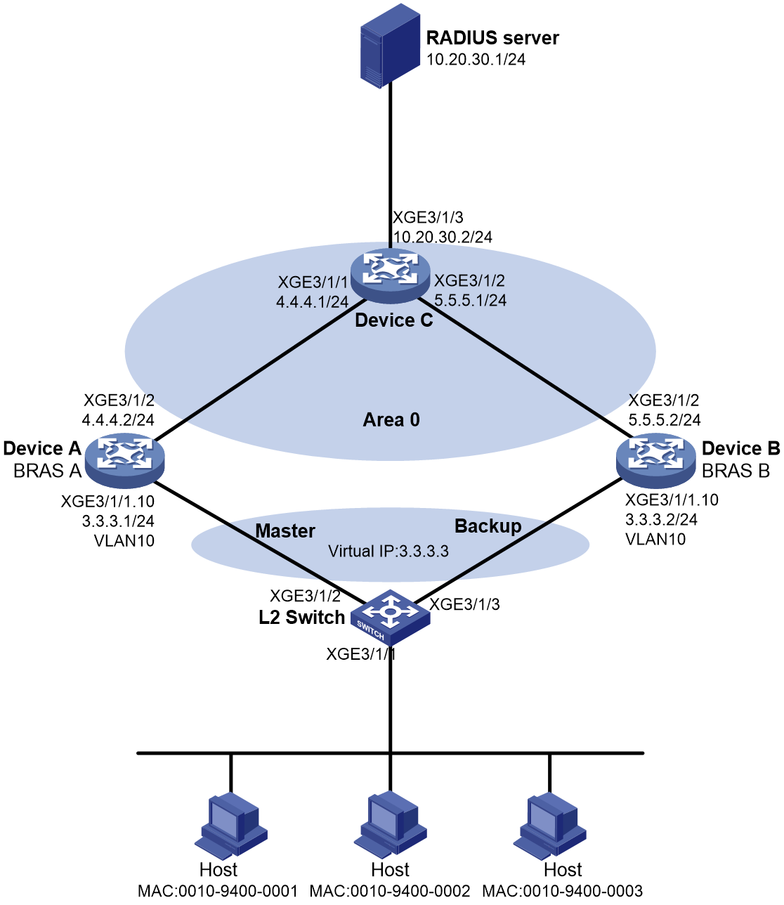
As shown in Figure 3, the hosts use IPoE to access the BRAS devices (Device A and Device B). The two BRAS devices are in a VSRP group. IPv4 address pool 1 is enabled on the BRAS devices. The hosts obtain IP addresses through DHCP from the master. Perform the following tasks:
· Enable IPoE and enable the DHCPv4 user on Ten-GigabitEthernet 3/1/1 of both Device A and Device B.
· Create VRRP group 1 on Ten-GigabitEthernet 3/1/1.10, and configure the subinterface to terminate VLAN-tagged packets whose outermost VLAN ID is 10.
· Enable OSPF on Device A and Device B to ensure that they can learn and advertise routes on their uplinks.
· Enable VSRP for IPoE to back up IPoE sessions in real time.
· Use the RADIUS server for authentication, authorization, and accounting of IPoE users.
Procedure
1. Assign IP addresses to interfaces, as shown in Figure 3. (Details not shown.)
2. Configure the RADIUS server (this example uses a FreeRADIUS server that runs on Linux):
# Add the NAS IP address and shared key configuration to the clients.conf configuration file. (The NAS IP addresses for the two clients are 4.4.4.2 and 5.5.5.2, respectively, and the shared key is radius.)
client 3.3.3.3/32 {
ipaddr = 3.3.3.3
netmask=32
secret=radius
}
# Add the IPoE user configuration to the users file. (The MAC addresses of the three IPoE users are 0010-9400-0001, 0010-9400-0002, and 0010-9400-0003. The password is radius, and the name of the authorized address pool is 1.)
001094000001 Cleartext-Password :="radius"
Framed-Pool = 1
001094000002 Cleartext-Password :="radius"
Framed-Pool = 1
001094000003 Cleartext-Password :="radius"
Framed-Pool = 1
3. Configure Device A:
a. Configure a VRRP group:
# Enter Ten-GigabitEthernet 3/1/1.10 interface view.
<DeviceA> system-view
[DeviceA] interface ten-gigabitethernet 3/1/1.10
# Create VRRP group 1 and set its virtual IP address to 3.3.3.3.
[DeviceA–Ten-GigabitEthernet3/1/1.10] vrrp vrid 1 virtual-ip 3.3.3.3
# Configure Ten-GigabitEthernet 3/1/1.10 to terminate VLAN 10.
[DeviceA-Ten-GigabitEthernet3/1/1.10] vlan-type dot1q vid 10
# Set the priority of Device A to 250 in VRRP group 1 on Ten-GigabitEthernet 3/1/1.10. Device A is assigned a higher priority than Device B in VRRP group 1, so Device A can become the master.
[DeviceA-Ten-GigabitEthernet3/1/1.10] vrrp vrid 1 priority 250
# Configure Device A to operate in preemptive mode, and set the preemption delay to 90000 centiseconds (15 minutes). When the original master recovers, it has 15 minutes to synchronize data from the new master before switch-back to ensure stability and data consistency of the VRRP group.
[DeviceA–Ten-GigabitEthernet3/1/1.10] vrrp vrid 1 preempt-mode delay 90000
[DeviceA–Ten-GigabitEthernet3/1/1.10] quit
# Create track entry 1 to monitor the link status of uplink interface Ten-GigabitEthernet 3/1/2. When the uplink fails, the track entry transits to Negative state.
[DeviceA] track 1 interface ten-gigabitethernet 3/1/2
# Associate VRRP group 1 on Ten-GigabitEthernet 3/1/1.10 with track entry 1, and decrease the device priority by 200 when the state of track entry 1 changes to Negative.
[DeviceA] interface ten-gigabitethernet 3/1/1.10
[DeviceA-Ten-GigabitEthernet3/1/1.10] vrrp vrid 1 track 1 priority reduced 200
[DeviceA-Ten-GigabitEthernet3/1/1.10] quit
b. Configure VSRP instance vs1:
# Create VSRP group pr1 and enter VSRP peer view.
[DeviceA] vsrp peer pr1
# Specify the local IP address as 4.4.4.2 and the peer IP address as 5.5.5.2 for VSRP to establish VSRP channels. The default TCP port number for the control channel is used.
[DeviceA-vsrp-peer-pr1] peer 5.5.5.2 local 4.4.4.2
[DeviceA-vsrp-peer-pr1] quit
# Create VSRP instance vs1 and enter its view.
[DeviceA] vsrp instance vs1
# Associate VSRP instance vs1 with VSRP group pr1 and set its backup ID to 1.
[DeviceA-vsrp-instance-vs1] backup id 1 peer pr1
# Bind VSRP instance vs1 to VRRP group 1 on Ten-GigabitEthernet 3/1/1.10.
[DeviceA-vsrp-instance-vs1] bind vrrp vrid 1 interface ten-gigabitethernet 3/1/1.10
# Specify the logical NAS IP address as 3.3.3.3.
[DeviceA-vsrp-instance-vs1] nas ip 3.3.3.3
# Specify the logical interface as Ten-GigabitEthernet 3/1/2.
[DeviceA-vsrp-instance-vs1] nas port ten-gigabitethernet 3/1/2
[DeviceA-vsrp-instance-vs1] quit
# Create a RADIUS scheme named rs1 and enter RADIUS scheme view.
[DeviceA] radius scheme rs1
# Specify the primary authentication server and primary accounting server.
[DeviceA-radius-rs1] primary authentication 10.20.30.1
[DeviceA-radius-rs1] primary accounting 10.20.30.1
# Set the shared key for secure RADIUS authentication and accounting communication.
[DeviceA-radius-rs1] key authentication simple radius
[DeviceA-radius-rs1] key accounting simple radius
# Configure Device A to remove the domain name in the username sent to the RADIUS servers for RADIUS scheme rs1.
[DeviceA-radius-rs1] user-name-format without-domain
# Specify the source IP address as 3.3.3.3 (the gateway address for the hosts) for outgoing RADIUS packets.
[DeviceA-radius-rs1] nas-ip 3.3.3.3
[DeviceA-radius-rs1] quit
# Enable the session-control feature.
[DeviceA] radius session-control enable
d. Configure an authentication domain:
# Create ISP domain dm1 and enter ISP domain view.
[DeviceA] domain name dm1
# Configure the domain to use RADIUS scheme rs1 for authentication, authorization, and accounting for IPoE users.
[DeviceA-isp-dm1] authentication ipoe radius-scheme rs1
[DeviceA-isp-dm1] authorization ipoe radius-scheme rs1
[DeviceA-isp-dm1] accounting ipoe radius-scheme rs1
[DeviceA-isp-dm1] quit
e. Configure the DHCP server:
# Enable DHCP.
[DeviceA] dhcp enable
[DeviceA] dhcp server request-ip-address check
# Create IPv4 address pool 1 and associate the pool with VSRP instance vs1.
[DeviceA] ip pool 1
[DeviceA-ip-pool-1] vsrp-instance vs1
# Assign gateway address 3.3.3.3 to the hosts, and export the host route destined for the hosts and the route destined for 3.3.3.0/24.
[DeviceA-ip-pool-1] network 3.3.3.0 mask 255.255.255.0 export-route
[DeviceA-ip-pool-1] gateway-list 3.3.3.3 export-route
# Exclude addresses from dynamic allocation.
[DeviceA-ip-pool-1] forbidden-ip 3.3.3.1 3.3.3.2 3.3.3.3
[DeviceA-ip-pool-1] quit
f. Configure IPoE authentication on Ten-GigabitEthernet 3/1/1:
# Enter Ten-GigabitEthernet 3/1/1 interface view.
[DeviceA] interface ten-gigabitethernet 3/1/1
# Enable IPoE and specify Layer 2 access mode.
[DeviceA–Ten-GigabitEthernet3/1/1] ip subscriber l2-connected enable
# Configure ISP domain dm1 for DHCPv4 users.
[DeviceA–Ten-GigabitEthernet3/1/1] ip subscriber dhcp domain dm1
# Set the password to radius in plain text for the dynamic IPoE users.
[DeviceA–Ten-GigabitEthernet3/1/1] ip subscriber password plaintext radius
# Associate Ten-GigabitEthernet 3/1/1 with VSRP instance vs1.
[DeviceA–Ten-GigabitEthernet3/1/1] bras vsrp-instance vs1
[DeviceA–Ten-GigabitEthernet3/1/1] dhcp vsrp-instance vs1
[DeviceA–Ten-GigabitEthernet3/1/1] quit
# Enable unclassified-IPv4 packet initiation.
[DeviceA–Ten-GigabitEthernet3/1/1] ip subscriber initiator unclassified-ip enable matching-user
# Enable ARP packet initiation.
[DeviceA–Ten-GigabitEthernet3/1/1] ip subscriber initiator arp enable
[DeviceA–Ten-GigabitEthernet3/1/1] quit
# Specify TCP port 1025 for VSRP to establish data channels for IPoE session backup (not required if the default port is used).
[DeviceA] bras vsrp-port 1025
g. Configure OSPF:
# Enable OSPF process 1 and set its router ID to 4.4.4.2 (the IP address of Ten-GigabitEthernet 3/1/2).
[DeviceA] ospf 1 router-id 4.4.4.2
# Configure OSPF to redistribute the user network route filtered by routing policy 1. Device A then advertises the user network route destined for the subnet where the hosts reside to Device C. In this way, Device C can select the route to a host based on the state of Device A and Device B in the VSRP instance.
[DeviceA-ospf-1] import-route unr inherit-cost route-policy 1
[DeviceA-ospf-1] quit
# Configure routing policy 1 to permit routes destined for network 3.3.3.0/24.
[DeviceA] ip prefix-list 1 permit 3.3.3.0 24
[DeviceA] route-policy 1 permit node 1
[DeviceA-route-policy-1-1] if-match ip address prefix-list 1
[DeviceA-route-policy-1-1] quit
# Create Area 0 and specify Ten-GigabitEthernet 3/1/2 whose IP address is on network 4.4.4.0/24 to run OSPF in Area 0.
[DeviceA] ospf
[DeviceA-ospf-1] area 0.0.0.0
[DeviceA-ospf-1-area-0.0.0.0] network 4.4.4.0 0.0.0.255
4. Configure Device B:
a. Configure a VRRP group:
# Enter Ten-GigabitEthernet 3/1/1.10 interface view.
<DeviceB> system-view
[DeviceB] interface ten-gigabitethernet 3/1/1.10
# Create VRRP group 1 and set its virtual IP address to 3.3.3.3.
[DeviceB–Ten-GigabitEthernet3/1/1.10] vrrp vrid 1 virtual-ip 3.3.3.3
# Configure Ten-GigabitEthernet 3/1/1.10 to terminate VLAN 10.
[DeviceB-Ten-GigabitEthernet3/1/1.10] vlan-type dot1q vid 10
# Set the priority of Device B to 200 in VRRP group 1 on Ten-GigabitEthernet 3/1/1.10. Device B is assigned a lower priority than Device A in VRRP group 1, so Device A can become the master.
[DeviceB-Ten-GigabitEthernet3/1/1.10] vrrp vrid 1 priority 200
# Configure Device B to operate in preemptive mode without setting the preemption delay. When the priority of the master decreases in the VRRP group, the backup can immediately take over as the new master for service continuity.
[DeviceB–Ten-GigabitEthernet3/1/1.10] vrrp vrid 1 preempt-mode
[DeviceB–Ten-GigabitEthernet3/1/1.10] quit
b. Configure VSRP instance vs1:
# Create VSRP group pr1 and enter VSRP peer view.
[DeviceB] vsrp peer pr1
# Specify the local IP address as 5.5.5.2 and the peer IP address as 4.4.4.2 for VSRP to establish VSRP channels. The default TCP port number for the control channel is used.
[DeviceB-vsrp-peer-pr1] peer 4.4.4.2 local 5.5.5.2
[DeviceB-vsrp-peer-pr1] quit
# Create VSRP instance vs1 and enter its view.
[DeviceB] vsrp instance vs1
# Associate VSRP instance vs1 with VSRP group pr1 and set its backup ID to 1.
[DeviceB-vsrp-instance-vs1] backup id 1 peer pr1
# Bind VSRP instance vs1 to VRRP group 1 on Ten-GigabitEthernet 3/1/1.10.
[DeviceB-vsrp-instance-vs1] bind vrrp vrid 1 interface ten-gigabitethernet 3/1/1.10
# Specify the logical NAS IP address as 3.3.3.3.
[DeviceB-vsrp-instance-vs1] nas ip 3.3.3.3
# Specify the logical interface as Ten-GigabitEthernet 3/1/2.
[DeviceB-vsrp-instance-vs1] nas port ten-gigabitethernet 3/1/2
[DeviceB-vsrp-instance-vs1] quit
c. Configure a RADIUS scheme:
# Create a RADIUS scheme named rs1 and enter RADIUS scheme view.
[DeviceB] radius scheme rs1
# Specify the primary authentication server and primary accounting server.
[DeviceB-radius-rs1] primary authentication 10.20.30.1
[DeviceB-radius-rs1] primary accounting 10.20.30.1
# Set the shared key for secure RADIUS authentication and accounting communication.
[DeviceB-radius-rs1] key authentication simple radius
[DeviceB-radius-rs1] key accounting simple radius
# Configure Device B to remove the domain name in the username sent to the RADIUS servers for RADIUS scheme rs1.
[DeviceB-radius-rs1] user-name-format without-domain
# Specify the source IP address as 3.3.3.3 (the gateway address for the hosts) for outgoing RADIUS packets.
[DeviceB-radius-rs1] nas-ip 3.3.3.3
[DeviceB-radius-rs1] quit
# Enable the session-control feature.
[DeviceB] radius session-control enable
d. Configure an authentication domain:
# Create ISP domain dm1 and enter ISP domain view.
[DeviceB] domain name dm1
# Configure the domain to use RADIUS scheme rs1 for authentication, authorization, and accounting for IPoE users.
[DeviceB-isp-dm1] authentication ipoe radius-scheme rs1
[DeviceB-isp-dm1] authorization ipoe radius-scheme rs1
[DeviceB-isp-dm1] accounting ipoe radius-scheme rs1
[DeviceB-isp-dm1] quit
e. Configure the DHCP server:
# Enable DHCP.
[DeviceB] dhcp enable
[DeviceB] dhcp server request-ip-address check
# Create IPv4 address pool 1 and associate the pool with VSRP instance vs1.
[DeviceB] ip pool 1
[DeviceB-ip-pool-1] vsrp-instance vs1
# Assign gateway address 3.3.3.3 to the hosts, and export the host route destined for the hosts and the route destined for 3.3.3.0/24.
[DeviceB-ip-pool-1] network 3.3.3.0 mask 255.255.255.0 export-route
[DeviceB-ip-pool-1] gateway-list 3.3.3.3 export-route
# Exclude addresses from dynamic allocation.
[DeviceB-ip-pool-1] forbidden-ip 3.3.3.1 3.3.3.2 3.3.3.3
[DeviceB-ip-pool-1] quit
f. Configure IPoE authentication on Ten-GigabitEthernet 3/1/1:
# Enter Ten-GigabitEthernet 3/1/1 interface view.
[DeviceB] interface ten-gigabitethernet 3/1/1
# Enable IPoE and specify Layer 2 access mode.
[DeviceB–Ten-GigabitEthernet3/1/1] ip subscriber l2-connected enable
# Configure ISP domain dm1 for DHCPv4 users.
[DeviceB–Ten-GigabitEthernet3/1/1] ip subscriber dhcp domain dm1
# Set the password to radius in plain text for the dynamic IPoE users.
[DeviceB–Ten-GigabitEthernet3/1/1] ip subscriber password plaintext radius
# Associate Ten-GigabitEthernet 3/1/1 with VSRP instance vs1.
[DeviceB–Ten-GigabitEthernet3/1/1] bras vsrp-instance vs1
[DeviceB–Ten-GigabitEthernet3/1/1] dhcp vsrp-instance vs1
[DeviceB–Ten-GigabitEthernet3/1/1] quit
# Enable unclassified-IPv4 packet initiation.
[DeviceB–GigabitEthernet1/0/1] ip subscriber initiator unclassified-ip enable matching-user
# Enable ARP packet initiation.
[DeviceB–GigabitEthernet1/0/1] ip subscriber initiator arp enable
[DeviceB–GigabitEthernet1/0/1] quit
# Specify TCP port number 1025 for VSRP to establish data channels for IPoE session backup (not required if the default port is used).
[DeviceB] bras vsrp-port 1025
g. Configure OSPF:
# Enable OSPF process 1 and set its router ID to 5.5.5.2 (the IP address of Ten-GigabitEthernet 3/1/2).
[DeviceB] ospf 1 router-id 5.5.5.2
# Configure OSPF to redistribute the user network route filtered by routing policy 1. Device B then advertises the user network route destined for the subnet where the hosts reside to Device C. In this way, Device C can select the route to a host based on the state of Device A and Device B in the VSRP instance.
[DeviceB-ospf-1] import-route unr inherit-cost route-policy 1
[DeviceB-ospf-1] quit
# Configure routing policy 1 to permit routes destined for network 3.3.3.0/24.
[DeviceB] ip prefix-list 1 permit 3.3.3.0 24
[DeviceB] route-policy 1 permit node 1
[DeviceB-route-policy-1-1] if-match ip address prefix-list 1
[DeviceB-route-policy-1-1] quit
# Create Area 0 and specify Ten-GigabitEthernet 3/1/2 whose IP address is on network 5.5.5.0/24 to run OSPF in Area 0.
[DeviceB] ospf
[DeviceB-ospf-1] area 0.0.0.0
[DeviceB-ospf-1-area-0.0.0.0] network 5.5.5.0 0.0.0.255
5. Configure Device C:
# Enable OSPF process 1 and set its router ID to 4.4.4.1 (the IP address of Ten-GigabitEthernet 3/1/1).
<DeviceC> system-view
[DeviceC] ospf 1 router-id 4.4.4.1
# Configure OSPF Area 0.
[DeviceC-ospf-1] area 0.0.0.0
[DeviceC-ospf-1-area-0.0.0.0] network 4.4.4.0 0.0.0.255
[DeviceC-ospf-1-area-0.0.0.0] network 5.5.5.0 0.0.0.255
[DeviceC-ospf-1-area-0.0.0.0] quit
[DeviceC-ospf-1] quit
6. Configure the L2 Switch:
a. Create VLAN 10.
<L2Switch> system-view
[L2Switch] vlan 10
[L2Switch-vlan10] quit
b. Configure VLAN settings on the interfaces that connect to Device A and Device B:
# Assign Ten-GigabitEthernet 3/1/2 to VLAN 10.
[L2Switch] interface ten-gigabitethernet 3/1/2
[L2Switch-Ten-GigabitEthernet3/1/2] port link-type trunk
[L2Switch-Ten-GigabitEthernet3/1/2] port trunk permit vlan 10
[L2Switch-Ten-GigabitEthernet3/1/2] quit
# Assign Ten-GigabitEthernet 3/1/3 to VLAN 10.
[L2Switch] interface ten-gigabitethernet 3/1/3
[L2Switch-Ten-GigabitEthernet3/1/3] port link-type trunk
[L2Switch-Ten-GigabitEthernet3/1/3] port trunk permit vlan 10
[L2Switch-Ten-GigabitEthernet3/1/3] quit
Verifying the configuration
# Verify that Device A and Device B have the same IPoE user information about authenticated IPoE users.
· On the master:
[DeviceA] display access-user
UserID Interface IP address MAC address S-/C-VLAN
Username Access type
IPv6 address
0x1 XGE3/1/1 3.3.3.4 0010-9400-0001 -/-
00109400000 L2 IPoE dynamic(D/-)
-
0x2 XGE3/1/1 3.3.3.5 0010-9400-0002 -/-
001094000002 L2 IPoE dynamic(D/-)
-
0x3 XGE3/1/1 3.3.3.6 0010-9400-0003 -/-
001094000003 L2 IPoE dynamic(D/-)
-
· On the backup:
[DeviceB] display access-user
UserID Interface IP address MAC address S-/C-VLAN
Username Access type
IPv6 address
0x1 XGE3/1/1 3.3.3.4 0010-9400-0001 -/-
001094000001 L2 IPoE dynamic(D/-)
-
0x2 XGE3/1/1 3.3.3.5 0010-9400-0002 -/-
001094000002 L2 IPoE dynamic(D/-)
-
0x3 XGE3/1/1 3.3.3.6 0010-9400-0003 -/-
001094000003 L2 IPoE dynamic(D/-)
-
Example: Configuring VSRP for IPoE (IPv6 address pool)
Network configuration
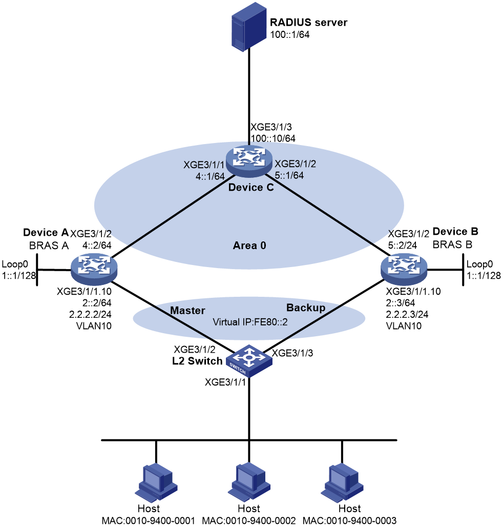
As shown in Figure 4, the hosts use IPoE to access the BRAS devices (Device A and Device B). The two BRAS devices are in a VSRP group. IPv6 address pool 1 is enabled on the BRAS devices. The hosts obtain IP addresses through DHCP from the master. Perform the following tasks:
· Enable IPoE and enable the DHCPv6 user on Ten-GigabitEthernet 3/1/1 of both Device A and Device B.
· Enable OSPF on Device A and Device B to ensure that they can learn and advertise routes on their uplinks.
· Enable VSRP for IPoE to back up IPoE sessions in real time.
· Use the RADIUS server for authentication, authorization, and accounting of IPoE users.
Figure 4 Network diagram
Procedure
1. Assign IPv6 addresses to interfaces, as shown in Figure 4. (Details not shown.)
2. Configure the RADIUS server (this example uses a FreeRADIUS server that runs on Linux):
# Add the NAS IP address and shared key configuration to the clients.conf configuration file. (The NAS IP address for the client is 1::1/128, and the shared key is radius.)
client 1::1/128 {
ipaddr = 1::1
netmask=128
secret=radius
}
# Add the IPoE user configuration to the users file. (The MAC addresses of the three IPoE users are 0010-9400-0001, 0010-9400-0002, and 0010-9400-0003. The password is radius, and the name of the authorized address pool is 1.)
001094000001 Cleartext-Password :="radius"
Framed-IPV6-Pool = 1
001094000002 Cleartext-Password :="radius"
Framed-IPV6-Pool = 1
001094000003 Cleartext-Password :="radius"
Framed-IPV6-Pool = 1
3. Configure Device A:
a. Configure a VRRP group:
# Configure Ten-GigabitEthernet 3/1/1.10 to terminate VLAN 10.
<DeviceA> system-view
[DeviceA] interface ten-gigabitethernet 3/1/1.10
[DeviceA–Ten-GigabitEthernet3/1/1.10] vlan-type dot1q vid 10
# Create IPv6 VRRP group 1 and set its virtual IP address to fe80::2.
[DeviceA–Ten-GigabitEthernet3/1/1.10] vrrp ipv6 vrid 1 virtual-ip fe80::2 link-local
# Configure Ten-GigabitEthernet 3/1/1.10 to automatically generate a link-local address.
[DeviceA–Ten-GigabitEthernet3/1/1.10] ipv6 address auto link-local
# Set the priority of Device A to 250 in VRRP group 1 on Ten-GigabitEthernet 3/1/1.10. Device A is assigned a higher priority than Device B in VRRP group 1, so Device A can become the master.
[DeviceA-Ten-GigabitEthernet3/1/1.10] vrrp ipv6 vrid 1 priority 250
# Configure Device A to operate in preemptive mode, and set the preemption delay to 90000 centiseconds (15 minutes). When the original master recovers, it has 15 minutes to synchronize data from the new master before switch-back to ensure stability and data consistency of the VRRP group.
[DeviceA–Ten-GigabitEthernet3/1/1.10] vrrp ipv6 vrid 1 preempt-mode delay 90000
[DeviceA–Ten-GigabitEthernet3/1/1.10] quit
# Create track entry 1 to monitor the link status of uplink interface Ten-GigabitEthernet 3/1/2. When the uplink fails, the track entry transits to Negative state.
[DeviceA] track 1 interface ten-gigabitethernet 3/1/2
# Associate VRRP group 1 on Ten-GigabitEthernet 3/1/1.10 with track entry 1 and decrease the device priority by 200 when the state of track entry 1 changes to Negative.
[DeviceA] interface ten-gigabitethernet 3/1/1.10
[DeviceA-Ten-GigabitEthernet3/1/1.10] vrrp ipv6 vrid 1 track 1 priority reduced 200
[DeviceA-Ten-GigabitEthernet3/1/1.10] quit
b. Configure VSRP instance vs1:
# Create VSRP group pr1 and enter VSRP peer view.
[DeviceA] vsrp peer pr1
# Specify the local IP address as 4::2 and the peer IP address as 5::2 for VSRP to establish VSRP channels. The default TCP port number for the control channel is used.
[DeviceA-vsrp-peer-pr1] peer ipv6 5::2 local 4::2
[DeviceA-vsrp-peer-pr1] quit
# Create VSRP instance vs1 and enter its view.
[DeviceA] vsrp instance vs1
# Associate VSRP instance vs1 with VSRP group pr1 and set its backup ID to 1.
[DeviceA-vsrp-instance-vs1] backup id 1 peer pr1
# Bind VSRP instance vs1 to IPv6 VRRP group 1 on Ten-GigabitEthernet 3/1/1.10.
[DeviceA-vsrp-instance-vs1] bind vrrp ipv6 vrid 1 interface ten-gigabitethernet 3/1/1.10
# Specify the logical host name as abc.
[DeviceA-vsrp-instance-vs1] nas id abc
# Specify the logical interface as Ten-GigabitEthernet 3/1/2.
[DeviceA-vsrp-instance-vs1] nas port ten-gigabitethernet 3/1/2
[DeviceA-vsrp-instance-vs1] quit
c. Configure a RADIUS scheme:
# Create a RADIUS scheme named rs1 and enter RADIUS scheme view.
[DeviceA] radius scheme rs1
# Specify the primary authentication server and primary accounting server.
[DeviceA-radius-rs1] primary authentication ipv6 100::1
[DeviceA-radius-rs1] primary accounting ipv6 100::1
# Set the shared key for secure RADIUS authentication and accounting communication.
[DeviceA-radius-rs1] key authentication simple radius
[DeviceA-radius-rs1] key accounting simple radius
# Configure Device A to remove the domain name in the username sent to the RADIUS servers for RADIUS scheme rs1.
[DeviceA-radius-rs1] user-name-format without-domain
# Specify the source IPv6 address as 1::1 for outgoing RADIUS packets.
[DeviceA-radius-rs1] nas-ip ipv6 1::1
[DeviceA-radius-rs1] quit
# Enable the session-control feature.
[DeviceA] radius session-control enable
d. Configure an authentication domain:
# Create ISP domain dm1 and enter ISP domain view.
[DeviceA] domain name dm1
# Configure authentication, authorization, and accounting methods for IPoE users.
[DeviceA-isp-dm1] authentication ipoe radius-scheme rs1
[DeviceA-isp-dm1] authorization ipoe radius-scheme rs1
[DeviceA-isp-dm1] accounting ipoe radius-scheme rs1
[DeviceA-isp-dm1] quit
e. Configure a loopback interface:
# Create track entry 10 and associate it with IPv6 VRRP group 1.
[DeviceA] track 10 vrrp ipv6 interface gigabitethernet1/0/1.10 vrid 1
# Enable OSPFv3 process 1 and specify Area 0 on Loopback 0.
[DeviceA] interface loopback 0
[DeviceA-LoopBack0] ip addres 1::1/128
[DeviceA-LoopBack0] ipv6 route-direct track 10 degrade-cost 90
[DeviceA-LoopBack0] quit
f. Configure the DHCPv6 server:
# Enable DHCP.
[DeviceA] dhcp enable
# Enable DHCPv6 server on Ten-GigabitEthernet 3/1/1.
[DeviceA] interface ten-gigabitethernet 3/1/1
[DeviceA–Ten-GigabitEthernet3/1/1] ipv6 dhcp select server
# Disable RA message suppression on Ten-GigabitEthernet 3/1/1.
[DeviceA–Ten-GigabitEthernet3/1/1] undo ipv6 nd ra halt
# Set the M flag to 1 and the O flag to 1 in RA advertisements to be sent. The receiving hosts can obtain IPv6 addresses and other configuration information from the DHCPv6 server.
[DeviceA–Ten-GigabitEthernet3/1/1] ipv6 nd autoconfig managed-address-flag
[DeviceA–Ten-GigabitEthernet3/1/1] ipv6 nd autoconfig other-flag
[DeviceA–Ten-GigabitEthernet3/1/1] quit
# Create address pool 1.
[DeviceA] ipv6 pool 1
# Specify subnet 3::/64 in address pool 1 and advertise the subnet.
[DeviceA-ipv6-pool-1] network 3::/64 export-route
[DeviceA-ipv6-pool-1] gateway-list 3::1
# Associate IPv6 address pool 1 with VSRP instance vs1.
[DeviceA-ipv6-pool-1] vsrp-instance vs1
# Configure IPv6 address pool 1 to use the virtual DUID generated based on enterprise number 2 and identifier ff.
[DeviceA-ipv6-pool-1] virtual-duid enterprise-number 2 identifier ff
[DeviceA-ipv6-pool-1] quit
# Exclude IPv6 address 3::1 from dynamic allocation.
[DeviceA-ipv6-pool-1] forbidden-address 3::1
[DeviceA-ipv6-pool-1] quit
g. Specify a virtual IPv6 address for Ten-GigabitEthernet 3/1/1:
# Enter Ten-GigabitEthernet 3/1/1 interface view.
[DeviceA] interface ten-gigabitethernet 3/1/1
# Specify a virtual IPv6 address of fe80::100 for Ten-GigabitEthernet 3/1/1, and bind it to VSRP instance vs1.
[DeviceA–Ten-GigabitEthernet3/1/1] ipv6 virtual-address fe80::100 vsrp vs1
h. Configure IPoE authentication on Ten-GigabitEthernet 3/1/1:
# Enable IPoE and specify Layer 2 access mode.
[DeviceA–Ten-GigabitEthernet3/1/1] ip subscriber l2-connected enable
# Configure ISP domain dm1 for DHCPv6 users.
[DeviceA–Ten-GigabitEthernet3/1/1] ip subscriber dhcp domain dm1
# Set the password to radius in plain text for the dynamic IPoE users.
[DeviceA–Ten-GigabitEthernet3/1/1] ip subscriber password plaintext radius
# Associate Ten-GigabitEthernet 3/1/1 with VSRP instance vs1.
[DeviceA–Ten-GigabitEthernet3/1/1] bras vsrp-instance vs1
[DeviceA–Ten-GigabitEthernet3/1/1] ipv6 dhcp vsrp-instance vs1
# Enable unclassified-IPv6 packet initiation.
[DeviceA–Ten-GigabitEthernet3/1/1] subscriber initiator unclassified-ipv6 enable matching-user
# Enable ARP packet initiation.
[DeviceA–Ten-GigabitEthernet3/1/1] ip subscriber initiator arp enable
[DeviceA–Ten-GigabitEthernet3/1/1] quit
[DeviceA] bras vsrp-port 1026
i. Configure OSPFv3:
# Enable OSPFv3 process 1 and set its router ID to 1.1.1.1.
[DeviceA] ospfv3
[DeviceA-ospfv3-1]router-id 1.1.1.1
# Configure OSPFv3 to redistribute direct routes and use the original cost of redistributed routes.
[DeviceA-ospfv3-1] import-route direct inherit-cost
# Configure OSPFv3 to redistribute the user network route filtered by routing policy 1. Device A then advertises the user network route destined for the subnet where the hosts reside to Device C. In this way, Device C can select the route to a host based on the state of Device A and Device B in the VSRP instance.
[DeviceA-ospfv3-1] import-route unr inherit-cost route-policy 1
[DeviceA-ospfv3-1] quit
# Configure routing policy 1 to permit routes destined for network 3::/64.
[DeviceA] ipv6 prefix-list 1 permit 3:: 64
[DeviceA] route-policy 1 permit node 1
[DeviceA-route-policy-1-1] if-match ipv6 address prefix-list 1
[DeviceA-route-policy-1-1] quit
# Enable OSPFv3 and specify Area 0 on Ten-GigabitEthernet 3/1/2.
[DeviceA] interface ten-gigabitethernet 3/1/2
[DeviceA–Ten-GigabitEthernet3/1/2] ospfv3 1 area 0
[DeviceA–Ten-GigabitEthernet3/1/2] quit
4. Configure Device B:
a. Configure a VRRP group:
<DeviceB> system-view
# Configure Ten-GigabitEthernet 3/1/1.10 to terminate VLAN 10.
[DeviceB] interface ten-gigabitethernet 3/1/1.10
[DeviceB–Ten-GigabitEthernet3/1/1.10] vlan-type dot1q vid 10
# Configure Ten-GigabitEthernet 3/1/1.10 to automatically generate a link-local address.
[DeviceB–Ten-GigabitEthernet3/1/1.10] ipv6 address auto link-local
# Create IPv6 VRRP group 1 and set its virtual IP address to fe80::2.
[DeviceB–Ten-GigabitEthernet3/1/1.10] vrrp ipv6 vrid 1 virtual-ip fe80::2 link-local
# Set the priority of Device B to 200 in VRRP group 1 on Ten-GigabitEthernet 3/1/1.10. Device B is assigned a lower priority than Device A in VRRP group 1, so Device A can become the master.
[DeviceB-Ten-GigabitEthernet3/1/1.10] vrrp ipv6 vrid 1 priority 200
# Configure Device B to operate in preemptive mode without setting the preemption delay. When the priority of the master decreases in the VRRP group, the backup can immediately take over as the new master for service continuity.
[DeviceB–Ten-GigabitEthernet3/1/1.10] vrrp ipv6 vrid 1 preempt-mode
[DeviceB–Ten-GigabitEthernet3/1/1.10] quit
b. Configure VSRP instance vs1:
# Create VSRP group pr1 and enter VSRP peer view.
[DeviceB] vsrp peer pr1
# Specify the local IP address as 5::2 and the peer IP address as 4::2 for VSRP to establish VSRP channels. The default TCP port number for the control channel is used.
[DeviceB-vsrp-peer-pr1] peer ipv6 4::2 local 5::2
[DeviceB-vsrp-peer-pr1] quit
# Create VSRP instance vs1 and enter its view.
[DeviceB] vsrp instance vs1
# Associate VSRP instance vs1 with VSRP group pr1 and set its backup ID to 1.
[DeviceB-vsrp-instance-vs1] backup id 1 peer pr1
# Bind VSRP instance vs1 to IPv6 VRRP group 1 on Ten-GigabitEthernet 3/1/1.10.
[DeviceB-vsrp-instance-vs1] bind vrrp ipv6 vrid 1 interface ten-gigabitethernet 3/1/1.10
# Specify the logical host name as abc.
[DeviceB-vsrp-instance-vs1] nas id abc
# Specify the logical interface as Ten-GigabitEthernet 3/1/2.
[DeviceB-vsrp-instance-vs1] nas port ten-gigabitethernet 3/1/2
[DeviceB-vsrp-instance-vs1] quit
c. Configure a RADIUS scheme:
# Create a RADIUS scheme named rs1 and enter RADIUS scheme view.
[DeviceB] radius scheme rs1
# Specify the primary authentication server and primary accounting server.
[DeviceB-radius-rs1] primary authentication ipv6 100::1
[DeviceB-radius-rs1] primary accounting ipv6 100::1
# Set the shared key for secure RADIUS authentication and accounting communication.
[DeviceB-radius-rs1] key authentication simple radius
[DeviceB-radius-rs1] key accounting simple radius
# Configure Device B to remove the domain name in the username sent to the RADIUS servers for RADIUS scheme rs1.
[DeviceB-radius-rs1] user-name-format without-domain
[DeviceB-radius-rs1] quit
# Enable the session-control feature.
[DeviceB] radius session-control enable
d. Configure an authentication domain:
# Create ISP domain dm1 and enter ISP domain view.
[DeviceB] domain name dm1
# Configure authentication, authorization, and accounting methods for IPoE users.
[DeviceB-isp-dm1] authentication ipoe radius-scheme rs1
[DeviceB-isp-dm1] authorization ipoe radius-scheme rs1
[DeviceB-isp-dm1] accounting ipoe radius-scheme rs1
[DeviceB-isp-dm1] quit
e. Configure a loopback interface:
# Create track entry 10 and associate it with IPv6 VRRP group 1.
[DeviceB] track 10 vrrp ipv6 interface gigabitethernet1/0/1.10 vrid 1
# Enable OSPFv3 process 1 and specify Area 0 on Loopback 0.
[DeviceB] interface loopback 0
[DeviceB-LoopBack0] ip addres 1::1/128
[DeviceB-LoopBack0] ipv6 route-direct track 10 degrade-cost 90
[DeviceB-LoopBack0] quit
# Configure OSPFv3 to redistribute direct routes and use the original cost of redistributed routes.
[DeviceB] ospfv3 1
[DeviceB-ospfv3-1] import-route direct inherit-cost
[DeviceB-ospfv3-1] quit
f. Configure the DHCPv6 server:
# Enable DHCP.
[DeviceB] dhcp enable
# Enable DHCPv6 server on Ten-GigabitEthernet 3/1/1.
[DeviceB] interface ten-gigabitethernet 3/1/1
[DeviceB–Ten-GigabitEthernet3/1/1] ipv6 dhcp select server
# Disable RA message suppression on Ten-GigabitEthernet 3/1/1.
[DeviceB–Ten-GigabitEthernet3/1/1] undo ipv6 nd ra halt
# Set the M flag to 1 and the O flag to 1 in RA advertisements to be sent. The receiving hosts can obtain IPv6 addresses and other configuration information from the DHCPv6 server.
[DeviceB–Ten-GigabitEthernet3/1/1] ipv6 nd autoconfig managed-address-flag
[DeviceB–Ten-GigabitEthernet3/1/1] ipv6 nd autoconfig other-flag
[DeviceB–Ten-GigabitEthernet3/1/1] quit
# Create address pool 1.
[DeviceB] ipv6 pool 1
# Specify subnet 3::/64 in address pool 1 and advertise the subnet.
[DeviceB-ipv6-pool-1] network 3::/64 export-route
[DeviceB-ipv6-pool-1] gateway-list 3::1
# Associate IPv6 address pool 1 with VSRP instance vs1.
[DeviceB-ipv6-pool-1] vsrp-instance vs1
# Configure IPv6 address pool 1 to use the virtual DUID generated based on enterprise number 2 and identifier ff.
[DeviceB-ipv6-pool-1] virtual-duid enterprise-number 2 identifier ff
[DeviceB-ipv6-pool-1] quit
# Exclude IPv6 address 3::1 from dynamic allocation.
[DeviceB-ipv6-pool-1] forbidden-address 3::1
[DeviceB-ipv6-pool-1] quit
g. Specify a virtual IPv6 address on Ten-GigabitEthernet 3/1/1:
# Enter Ten-GigabitEthernet 3/1/1 interface view.
[DeviceB] interface ten-gigabitethernet 3/1/1
# Specify a virtual IPv6 address of fe80::100 for Ten-GigabitEthernet 3/1/1, and bind it to VSRP instance vs1.
[DeviceB–Ten-GigabitEthernet3/1/1] ipv6 virtual-address fe80::100 vsrp vs1
h. Configure IPoE authentication on Ten-GigabitEthernet 3/1/1:
# Enable IPoE and specify Layer 2 access mode.
[DeviceB–Ten-GigabitEthernet3/1/1] ip subscriber l2-connected enable
# Configure ISP domain dm1 for DHCPv6 users.
[DeviceB–Ten-GigabitEthernet3/1/1] ip subscriber dhcp domain dm1
# Set the password to radius in plain text for the dynamic IPoE users.
[DeviceB–Ten-GigabitEthernet3/1/1] ip subscriber password plaintext radius
# Associate Ten-GigabitEthernet 3/1/1 with VSRP instance vs1.
[DeviceB–Ten-GigabitEthernet3/1/1] bras vsrp-instance vs1
[DeviceB–Ten-GigabitEthernet3/1/1] ipv6 dhcp vsrp-instance vs1
# Enable unclassified-IPv6 packet initiation.
[DeviceB–Ten-GigabitEthernet3/1/1] subscriber initiator unclassified-ipv6 enable matching-user
# Enable ARP packet initiation.
[DeviceB–Ten-GigabitEthernet3/1/1] ip subscriber initiator arp enable
[DeviceB–Ten-GigabitEthernet3/1/1] quit
# Specify TCP port 1026 for VSRP to establish data channels for IPoE session backup (not required if the default port is used).
[DeviceB] bras vsrp-port 1026
i. Configure OSPFv3:
# Enable OSPFv3 process 1 and set its router ID to 2.2.2.2.
[DeviceB] ospfv3
[DeviceB-ospfv3-1]router-id 2.2.2.2
# Configure OSPFv3 to redistribute direct routes and use the original cost of redistributed routes.
[DeviceB-ospfv3-1] import-route direct inherit-cost
# Configure OSPFv3 to redistribute the user network route filtered by routing policy 1. Device B then advertises the user network route destined for the subnet where the hosts reside to Device C. In this way, Device C can select the route to a host based on the state of Device A and Device B in the VSRP instance.
[DeviceB-ospfv3-1] import-route unr inherit-cost route-policy 1
[DeviceB-ospfv3-1] quit
# Configure routing policy 1 to permit routes destined for network 3::/32.
[DeviceB] ipv6 prefix-list 1 permit 3:: 32
[DeviceB] route-policy 1 permit node 1
[DeviceB-route-policy-1-1] if-match ipv6 address prefix-list 1
[DeviceB-route-policy-1-1] quit
# Enable OSPFv3 and specify Area 0 on Ten-GigabitEthernet 3/1/2.
[DeviceB] interface ten-gigabitethernet 3/1/2
[DeviceB–Ten-GigabitEthernet3/1/2] ospfv3 1 area 0
[DeviceB–Ten-GigabitEthernet3/1/2] quit
5. Configure Device C:
# Enable OSPFv3 process 1 and set its router ID to 3.3.3.3.
<DeviceC> system-view
[DeviceC] ospfv3
[DeviceC-ospfv3-1] router-id 3.3.3.3
# Enable OSPFv3 process 1 and specify Area 0 on Ten-GigabitEthernet 3/1/3.
[DeviceC] interface ten-gigabitethernet 3/1/3
[DeviceC-Ten-GigabitEthernet3/1/3] ospfv3 1 area 0
[DeviceC-Ten-GigabitEthernet3/1/3] quit
# Enable OSPFv3 process 1 and specify Area 0 on Ten-GigabitEthernet 3/1/1.
[DeviceC] interface ten-gigabitethernet 3/1/1
[DeviceC–Ten-GigabitEthernet3/1/1] ospfv3 1 area 0
[DeviceC–Ten-GigabitEthernet3/1/1] quit
# Enable OSPFv3 process 1 and specify Area 0 on Ten-GigabitEthernet 3/1/2.
[DeviceC] interface ten-gigabitethernet 3/1/2
[DeviceC–Ten-GigabitEthernet3/1/2] ospfv1 1 area 0
[DeviceC–Ten-GigabitEthernet3/1/2] quit
a. Create VLAN 10.
<L2Switch> system-view
[L2Switch] vlan 10
[L2Switch-vlan10] quit
b. Configure VLAN settings on the interfaces that connect to Device A and Device B:
# Assign Ten-GigabitEthernet 3/1/2 to VLAN 10.
[L2Switch] interface ten-gigabitethernet 3/1/2
[L2Switch-Ten-GigabitEthernet3/1/2] port link-type trunk
[L2Switch-Ten-GigabitEthernet3/1/2] port trunk permit vlan 10
[L2Switch-Ten-GigabitEthernet3/1/2] quit
# Assign Ten-GigabitEthernet 3/1/3 to VLAN 10.
[L2Switch] interface Ten-GigabitEthernet 3/1/3
[L2Switch-Ten-GigabitEthernet3/1/3] port link-type trunk
[L2Switch-Ten-GigabitEthernet3/1/3] port trunk permit vlan 10
[L2Switch-Ten-GigabitEthernet3/1/3] quit
Verifying the configuration
# Verify that Device A and Device B have the same IPoE user information about authenticated IPoE users.
· On the master:
[DeviceA] display access-user
UserID Interface IP address MAC address S-/C-VLAN
Username Access type
IPv6 address
0x1 XGE3/1/1 - 0010-9400-0001 -/-
001094000001 L2 IPoE dynamic(-/D)
3::1
0x2 XGE3/1/1 - 0010-9400-0002 -/-
001094000002 L2 IPoE dynamic(-/D)
3::2
0x3 XGE3/1/1 - 0010-9400-0003 -/-
001094000003 L2 IPoE dynamic(-/D)
3::3
· On the backup:
UserID Interface IP address MAC address S-/C-VLAN
Username Access type
IPv6 address
0x1 XGE3/1/1 - 0010-9400-0001 -/-
001094000001 L2 IPoE dynamic(-/D)
3::1
0x2 XGE3/1/1 - 0010-9400-0002 -/-
001094000002 L2 IPoE dynamic(-/D)
3::2
0x3 XGE3/1/1 - 0010-9400-0003 -/-
001094000003 L2 IPoE dynamic(-/D)
3::3
Example: Configuring VSRP for dual-stack IPoE (IPv4 and IPv6 address pools)
Network configuration
As shown in Figure 5, the hosts use IPoE to access BRAS A and BRAS B. The two BRAS devices are in a VSRP group. The hosts obtain IP addresses through DHCP from the master. Perform the following tasks:
· Enable IPoE on Ten-GigabitEthernet 3/1/1 of both BRAS A and BRAS B.
· Configure an IPv4 address pool and an IPv6 address pool on the BRAS devices.
· Create VRRP group 1 on Ten-GigabitEthernet 3/1/1.10, and configure the subinterface to terminate VLAN-tagged packets whose outermost VLAN ID is 10.
· Enable OSPF on BRAS A and BRAS B to ensure that they can learn and advertise routes on their uplinks.
· Enable VSRP for IPoE to back up IPoE sessions in real time.
· Use the RADIUS server for authentication, authorization, and accounting of IPoE users.
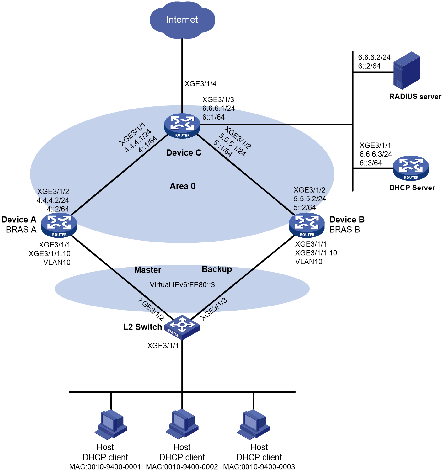
Procedure
1. Assign IP addresses to interfaces, as shown in Figure 5. (Details not shown.)
2. Configure the RADIUS server:
|
|
NOTE: This example uses a FreeRADIUS server that runs on Linux. |
# Add the NAS IP address and shared key configuration to the clients.conf configuration file. (The NAS IP address for the client is 3.3.3.3, and the shared key is 123456.)
client 3.3.3.3/32 {
ipaddr = 3.3.3.3
netmask=32
secret=123456
}
# Add the IPoE user configuration to the users file. (The MAC addresses of the three IPoE users are 0010-9400-0001, 0010-9400-0002, and 0010-9400-0003. The password is 123456.)
001094000001 Cleartext-Password :="123456"
001094000002 Cleartext-Password :="123456"
001094000003 Cleartext-Password :="123456"
3. Configure the DHCP server:
|
|
NOTE: This example uses a network device as the DHCP server. As a best practice, use a dedicated DHCP server. |
a. Configure the DHCPv4 server:
# Enable DHCP.
<DHCP> system-view
[DHCP] dhcp enable
# Enable the DHCP server to return a DHCP-NAK message if the client notions of their IP addresses are incorrect.
[DHCP] dhcp server request-ip-address check
# Create IPv4 address pool ipoev4 and enter its view.
[DHCP] ip pool ipoev4
# Assign subnet 3.3.3.0/24 to the hosts, and specify the gateway address and DNS server address.
[DHCP-ip-pool-ipoev4] network 3.3.3.0 24
[DHCP-ip-pool-ipoev4] gateway-list 3.3.3.3
[DHCP-ip-pool-ipoev4] dns-list 8.8.8.8
# Exclude the gateway address and the IP addresses of host-facing interfaces on the BRAS devices from dynamic allocation.
[DHCP-ip-pool-ipoev4] forbidden-ip 3.3.3.1
[DHCP-ip-pool-ipoev4] forbidden-ip 3.3.3.2
[DHCP-ip-pool-ipoev4] forbidden-ip 3.3.3.3
[DHCP-ip-pool-ipoev4] quit
# Configure a static route for the DHCPv4 server to reach the BRAS devices.
[DHCP] ip route-static 0.0.0.0 0 6.6.6.1
b. Configure the DHCPv6 server:
# Enable DHCPv6 server on Ten-GigabitEthernet 3/1/1.
[DHCP] interface ten-gigabitethernet 3/1/1
[DHCP–Ten-GigabitEthernet3/1/1] ipv6 dhcp select server
[DHCP–Ten-GigabitEthernet3/1/1] quit
# Create IPv6 address pool ipoev6 and enter its view.
[DHCP] ipv6 pool ipoev6
# Assign subnet 3::/64 to the hosts and specify DNS server address.
[DHCP-ipv6-pool-ipoev6] network 3::/64
[DHCP-ipv6-pool-ipoev6] dns-server 8::8
[DHCP-ipv6-pool-ipoev6] quit
# Exclude the gateway address and the IP addresses of host-facing interfaces on the BRAS devices from dynamic allocation.
[DHCP] ipv6 dhcp server forbidden-address 3::1
[DHCP] ipv6 dhcp server forbidden-address 3::2
[DHCP] ipv6 dhcp server forbidden-address 3::3
# Configure a static route for the DHCPv6 server to reach the BRAS devices.
[DHCP] ipv6 route-static 0::0 0 6::1
4. Configure BRAS A:
a. Configure an IPv6 VRRP group:
# Enter the view of Ten-GigabitEthernet 3/1/1.10.
<BRASA> system-view
[BRASA] interface ten-gigabitethernet 3/1/1.10
# Create IPv6 VRRP group 1 and set its virtual IP address to fe80::3.
[BRASA–Ten-GigabitEthernet3/1/1.10] vrrp ipv6 vrid 1 virtual-ip fe80::3 link-local
# Configure Ten-GigabitEthernet 3/1/1.10 to automatically generate a link-local address.
[BRASA–Ten-GigabitEthernet3/1/1.10] ipv6 address auto link-local
# Set the priority of BRAS A to 250 in VRRP group 1 on Ten-GigabitEthernet 3/1/1.10. BRAS A is assigned a higher priority than BRAS B in VRRP group 1, so BRAS A can become the master.
[BRASA-Ten-GigabitEthernet3/1/1.10] vrrp ipv6 vrid 1 priority 250
# Configure BRAS A to operate in preemptive mode, and set the preemption delay to 90000 centiseconds (15 minutes). When the original master recovers, it has 15 minutes to synchronize data from the new master before switch-back to ensure stability and data consistency of the VRRP group.
[BRASA–Ten-GigabitEthernet3/1/1.10] vrrp ipv6 vrid 1 preempt-mode delay 90000
[BRASA–Ten-GigabitEthernet3/1/1.10] quit
# Create track entry 1 to monitor the link status of uplink interface Ten-GigabitEthernet 3/1/2. When the uplink fails, the track entry transits to Negative state.
[BRASA] track 1 interface ten-gigabitethernet 3/1/2
[BRASA-track-1] quit
# Associate VRRP group 1 on Ten-GigabitEthernet 3/1/1.10 with track entry 1 and decrease the device priority by 200 when the state of track entry 1 changes to Negative.
[BRASA] interface ten-gigabitethernet 3/1/1.10
[BRASA-Ten-GigabitEthernet3/1/1.10] vrrp ipv6 vrid 1 track 1 priority reduced 200
# Configure Ten-GigabitEthernet 3/1/1.10 to terminate VLAN 10.
[BRASA-Ten-GigabitEthernet3/1/1.10] vlan-type dot1q vid 10
[BRASA-Ten-GigabitEthernet3/1/1.10] quit
b. Configure a VSRP instance:
|
|
NOTE: When VSRP is enabled for IPoE, IPv4 and IPv6 users share a data backup channel. You can configure an IPv4 or IPv6 data backup channel for dual-stack IPoE. This example creates an IPv6 data backup channel. |
# Create VSRP group pr1 and enter VSRP peer view.
[BRASA] vsrp peer pr1
# Specify the local IP address as 4::2 and the peer IP address as 5::2 for VSRP to establish VSRP channels. The default TCP port number for the control channel is used.
[BRASA-vsrp-peer-pr1] peer ipv6 5::2 local 4::2
[BRASA-vsrp-peer-pr1] quit
# Create VSRP instance vs1 and enter its view.
[BRASA] vsrp instance vs1
# Associate VSRP instance vs1 with VSRP group pr1 and set its backup ID to 1.
[BRASA-vsrp-instance-vs1] backup id 1 peer pr1
# Bind VSRP instance vs1 to IPv6 VRRP group 1 on Ten-GigabitEthernet 3/1/1.10.
[BRASA-vsrp-instance-vs1] bind vrrp ipv6 vrid 1 interface ten-gigabitethernet 3/1/1.10
# Specify the logical host name as abc.
[BRASA-vsrp-instance-vs1] nas id abc
# Specify the logical interface as Ten-GigabitEthernet 3/1/2.
[BRASA-vsrp-instance-vs1] nas port ten-gigabitethernet 3/1/2
# Enable route advertisement for the backup. Set the route costs for the master and the back to 20 and 30, respectively.
[BRASA-vsrp-instance-vs1] backup route-advertise master-cost 20 backup-cost 30
[BRASA-vsrp-instance-vs1] quit
c. Configure a RADIUS scheme:
# Create a RADIUS scheme named rs1 and enter RADIUS scheme view.
[BRASA] radius scheme rs1
# Specify the primary authentication server and primary accounting server.
[BRASA-radius-rs1] primary authentication 6.6.6.2
[BRASA-radius-rs1] primary accounting 6.6.6.2
# Set the shared key for secure RADIUS authentication and accounting communication.
[BRASA-radius-rs1] key authentication simple 123456
[BRASA-radius-rs1] key accounting simple 123456
# Specify the source IP address as 3.3.3.3 (the gateway address for the hosts) for outgoing RADIUS packets.
[BRASA-radius-rs1] nas-ip 3.3.3.3
[BRASA-radius-rs1] quit
d. Configure DHCPv4 relay agent:
# Enable DHCP.
[BRASA] dhcp enable
# Configure remote BAS IPv4 address pool ipoev4 and associate the pool with VSRP instance vs1.
[BRASA] ip pool ipoev4 bas remote
[BRASA-ip-pool-ipoev4] gateway 3.3.3.3 24
[BRASA-ip-pool-ipoev4] forbidden-ip 3.3.3.3
[BRASA-ip-pool-ipoev4] remote-server 6.6.6.3
[BRASA-ip-pool-ipoev4] vsrp-instance vs1
[BRASA-ip-pool-ipoev4] quit
# Configure BRASA acting as the VSRP master device to export the user network route (UNR) of subnet 3.3.3.0/24 to the routing table, so that it can use OSPF to redistribute the UNR and advertise it to uplink Device C. Device C can then distribute all traffic destined for the subnet to the master BRAS device.
|
|
NOTE: · By default, in a VSRP environment, the master and backup BRAS devices both require configuring the gateway 3.3.3.0 24 command. Only the master device exports the corresponding subnet route. When the master devices changes to backup device, the exported subnet route will be deleted. · The BRAS device in this example also acts as a DHCPv4 relay agent. Configuring the gateway 3.3.3.0 24 command is only for exporting user subnet route 3.3.3.0/24 to the routing table for implementing traffic distribution through OSPF. The configuration is not for address allocation purposes. |
# Associate Ten-GigabitEthernet 3/1/1 with VSRP instance vs1.
[BRASA] interface ten-gigabitethernet 3/1/1
[BRASA-Ten-GigabitEthernet3/1/1] dhcp vsrp-instance vs1
e. Configure DHCPv6 relay agent:
# Disable RA message suppression on Ten-GigabitEthernet 3/1/1. Set the managed address configuration flag (M) to 1 and set the other stateful configuration flag (O) to 1 in RA advertisements to be sent.
[BRASA–Ten-GigabitEthernet3/1/1] undo ipv6 nd ra halt
[BRASA–Ten-GigabitEthernet3/1/1] ipv6 nd autoconfig managed-address-flag
[BRASA–Ten-GigabitEthernet3/1/1] ipv6 nd autoconfig other-flag
# Enable the DHCPv6 relay agent on Ten-GigabitEthernet 3/1/1.
[BRASA–Ten-GigabitEthernet3/1/1] ipv6 dhcp select relay
# Configure remote IPv6 address pool ipoev6 and associate the pool with VSRP instance vs1.
[BRASA] ipv6 pool ipoev6
[BRASA-ipv6-pool-ipoev6] gateway 3::3 24
[BRASA-ipv6-pool-ipoev6] forbidden-ip 3.3.3.3
[BRASA-ipv6-pool-ipoev6] remote-server 6::3
[BRASA-ipv6-pool-ipoev6] vsrp-instance vs1
[BRASA-ipv6-pool-ipoev6] quit
# Configure BRASB acting as the VSRP master device to export the UNR of subnet 3::/24 to the routing table, so that it can use OSPFv3 to redistribute the UNR and advertise it to uplink Device C. Device C can then distribute all traffic destined for the subnet to the master BRAS device.
|
|
NOTE: · By default, in a VSRP environment, the master and backup BRAS devices both require configuring the network 3::/24 export-route command. Only the master device exports the corresponding subnet route. When the master devices changes to backup device, the exported subnet route will be deleted. · The BRAS device in this example also acts as a DHCPv6 relay agent. Configuring the network 3::/64 export-route command is only for exporting user subnet route 3::/64 to the routing table for implementing traffic distribution through OSPFv3. The configuration is not for address allocation purposes. |
[BRASB-ipv6-pool-ipoev6] network 3::/64 export-route
[BRASB-ipv6-pool-ipoev6] quit
# Associate Ten-GigabitEthernet 3/1/1 with VSRP instance vs1.
[BRASA] interface ten-gigabitethernet 3/1/1
[BRASA–Ten-GigabitEthernet3/1/1] ipv6 dhcp vsrp-instance vs1
[BRASA–Ten-GigabitEthernet3/1/1] quit
f. Configure an authentication domain:
# Create ISP domain dm1 and enter ISP domain view.
[BRASA] domain name dm1
# Configure the domain to use RADIUS scheme rs1 for authentication, authorization, and accounting for IPoE users.
[BRASA-isp-dm1] authentication ipoe radius-scheme rs1
[BRASA-isp-dm1] authorization ipoe radius-scheme rs1
[BRASA-isp-dm1] accounting ipoe radius-scheme rs1
# Configure an IPv4 address pool and an IPv6 address pool for users in the ISP domain.
[BRASA-isp-dm1] authorization-attribute ip-pool ipoev4
[BRASA-isp-dm1] authorization-attribute ipv6-pool ipoev6
[BRASA-isp-dm1] quit
g. Configure OSPF:
# Enable OSPF process 1 and specify its router ID as 3.3.3.1 (the IP address of Ten-GigabitEthernet 3/1/1.10).
[BRASA] ospf 1 router-id 3.3.3.1
# Configure OSPF to redistribute the user network route filtered by routing policy 1. When BRAS A acts as the master and assigns an IP address to a host, it advertises the user network route destined for the subnet where the host resides to Device C. In this way, Device C can select the route to the host based on the state of BRAS A and BRAS B in the VSRP instance.
[BRASA-ospf-1] import-route unr inherit-cost inherit-cost route-policy 1
[BRASA-ospf-1] quit
# Configure routing policy 1 to permit routes destined for 3.3.3.0/24.
[BRASA] ip prefix-list 1 permit 3.3.3.0 24
[BRASA] route-policy 1 permit node 1
[BRASA-route-policy-1-1] if-match ip address prefix-list 1
[BRASA-route-policy-1-1] quit
# Configure Area 0.
[BRASA] ospf
[BRASA-ospf-1] area 0.0.0.0
[BRASA-ospf-1-area-0.0.0.0] network 4.4.4.0 0.0.0.255
[BRASA-ospf-1-area-0.0.0.0] quit
[BRASA-ospf-1] quit
h. Configure OSPFv3:
# Enable OSPFv3 process 1 and specify its router ID as 3.3.3.1.
[BRASA] ospfv3
[BRASA-ospfv3-1] router-id 3.3.3.1
# Configure OSPFv3 to redistribute the user network route filtered by routing policy 1. BRAS A then advertises the user network route destined for the subnet where the host resides to Device C. In this way, Device C can select the route to the host based on the state of BRAS A and BRAS B in the VSRP instance.
[BRASA-ospfv3-1] import-route unr inherit-cost inherit-cost route-policy 1
[BRASA-ospfv3-1] quit
# Configure routing policy 1 to permit routes destined for 3::/64.
[BRASA] ipv6 prefix-list 1 permit 3:: 64
[BRASA] route-policy 1 permit node 1
[BRASA-route-policy-1-1] if-match ipv6 address prefix-list 1
[BRASA-route-policy-1-1] quit
# Configure Area 0 on Ten-GigabitEthernet 3/1/2.
[BRASA] interface ten-gigabitethernet 3/1/2
[BRASA–Ten-GigabitEthernet3/1/2] ospfv3 1 area 0
[BRASA–Ten-GigabitEthernet3/1/2] quit
i. Specify a virtual IPv6 address on Ten-GigabitEthernet 3/1/1:
# Enter the view of Ten-GigabitEthernet 3/1/1.
[BRASA] interface ten-gigabitethernet 3/1/1
# Specify a virtual IPv6 address of fe80::100 for Ten-GigabitEthernet 3/1/1, and bind it to VSRP instance vs1:.
[BRASA–Ten-GigabitEthernet3/1/1] ipv6 virtual-address fe80::100 vsrp vs1
j. Configure IPoE authentication on Ten-GigabitEthernet 3/1/1:
# Enable IPoE and specify Layer 2 access mode.
[BRASA–Ten-GigabitEthernet3/1/1] ip subscriber l2-connected enable
# Configure ISP domain dm1 for DHCP users.
[BRASA–Ten-GigabitEthernet3/1/1] ip subscriber dhcp domain dm1
# Configure the source MAC addresses as authentication usernames for DHCP users.
[BRASA–Ten-GigabitEthernet3/1/1] ip subscriber dhcp username include source-mac
# Set the password to 123456 in plain text for the dynamic IPoE users.
[BRASA–Ten-GigabitEthernet3/1/1] ip subscriber password plaintext 123456
# Associate Ten-GigabitEthernet 3/1/1 with VSRP instance vs1.
[BRASA–Ten-GigabitEthernet3/1/1] bras vsrp-instance vs1
[BRASA–Ten-GigabitEthernet3/1/1] quit
5. Configure BRAS B:
a. Configure an IPv6 VRRP group:
# Enter the view of Ten-GigabitEthernet 3/1/1.10.
<BRASB> system-view
[BRASB] interface ten-gigabitethernet 3/1/1.10
# Create IPv6 VRRP group 1 and set its virtual IP address to fe80::3.
[BRASB–Ten-GigabitEthernet3/1/1.10] vrrp ipv6 vrid 1 virtual-ip fe80::3 link-local
# Configure Ten-GigabitEthernet 3/1/1.10 to automatically generate a link-local address.
[BRASB–Ten-GigabitEthernet3/1/1.10] ipv6 address auto link-local
# Set the priority of BRAS B to 200 in VRRP group 1 on Ten-GigabitEthernet 3/1/1.10. BRAS A is assigned a higher priority than BRAS B in VRRP group 1, so BRAS A can become the master.
[BRASB-Ten-GigabitEthernet3/1/1.10] vrrp ipv6 vrid 1 priority 200
# Configure BRAS B to operate in preemptive mode without setting the preemption delay. When the priority of the master decreases in the VRRP group, the backup can immediately take over as the new master for service continuity.
[BRASB–Ten-GigabitEthernet3/1/1.10] vrrp ipv6 vrid 1 preempt-mode
# Configure Ten-GigabitEthernet 3/1/1.10 to terminate VLAN 10.
[BRASB-Ten-GigabitEthernet3/1/1.10] vlan-type dot1q vid 10
[BRASB–Ten-GigabitEthernet3/1/1.10] quit
b. Configure the track entry associated with the BFD session on Ten-GigabitEthernet 3/1/1.10:
# Create track entry 2 and associate it with a BFD session.
[BRASB] track 2 bfd echo interface ten-gigabitethernet 3/1/1.10 remote ip 3.3.3.1 local ip 3.3.3.2
[BRASB-track-2] quit
# Associate VRRP group 1 on Ten-GigabitEthernet 3/1/1.10 with track entry 2 and switch the master and the backup when the state of track entry 2 changes to Negative.
[BRASB] interface ten-gigabitethernet 3/1/1.10
[BRASB–Ten-GigabitEthernet3/1/1.10] vrrp ipv6 vrid 1 track 2 switchover
[BRASB–Ten-GigabitEthernet3/1/1.10] quit
c. Configure a VSRP instance:
|
|
NOTE: When VSRP is enabled for IPoE, IPv4 and IPv6 users share a data backup channel. You can configure an IPv4 or IPv6 data backup channel for dual-stack IPoE. This example creates an IPv6 data backup channel. |
# Create VSRP group pr1 and enter VSRP peer view.
[BRASB] vsrp peer pr1
# Specify the local IP address as 5::2 and the peer IP address as 4::2 for VSRP to establish VSRP channels. The default TCP port number for the control channel is used.
[BRASB-vsrp-peer-pr1] peer ipv6 4::2 local 5::2
[BRASB-vsrp-peer-pr1] quit
# Create VSRP instance vs1 and enter its view.
[BRASB] vsrp instance vs1
# Associate VSRP instance vs1 with VSRP group pr1 and set its backup ID to 1.
[BRASB-vsrp-instance-vs1] backup id 1 peer pr1
# Bind VSRP instance vs1 to IPv6 VRRP group 1 on Ten-GigabitEthernet 3/1/1.10.
[BRASB-vsrp-instance-vs1] bind vrrp ipv6 vrid 1 interface ten-gigabitethernet 3/1/1.10
# Specify the logical host name as abc.
[BRASB-vsrp-instance-vs1] nas id abc
# Specify the logical interface as Ten-GigabitEthernet 3/1/2.
[BRASB-vsrp-instance-vs1] nas port ten-gigabitethernet 3/1/2
# Enable route advertisement for the backup. Set the route costs for the master and the back to 20 and 30, respectively.
[BRASB-vsrp-instance-vs1] backup route-advertise master-cost 20 backup-cost 30
[BRASB-vsrp-instance-vs1] quit
d. Configure a RADIUS scheme:
# Create a RADIUS scheme named rs1 and enter RADIUS scheme view.
[BRASB] radius scheme rs1
# Specify the primary authentication server and primary accounting server.
[BRASB-radius-rs1] primary authentication 6.6.6.2
[BRASB-radius-rs1] primary accounting 6.6.6.2
# Set the shared key for secure RADIUS authentication and accounting communication.
[BRASB-radius-rs1] key authentication simple 123456
[BRASB-radius-rs1] key accounting simple 123456
# Specify the source IP address as 3.3.3.3 (the gateway address for hosts) for outgoing RADIUS packets.
[BRASB-radius-rs1] nas-ip 3.3.3.3
[BRASB-radius-rs1] quit
e. Configure DHCPv4 relay agent:
# Enable DHCP.
[BRASB] dhcp enable
# Configure remote BAS IPv4 address pool ipoev4 and associate the pool with VSRP instance vs1.
[BRASB] ip pool ipoev4 bas remote
[BRASB-ip-pool-ipoev4] gateway 3.3.3.3 24
[BRASB-ip-pool-ipoev4] forbidden-ip 3.3.3.3
[BRASB-ip-pool-ipoev4] remote-server 6.6.6.3
[BRASB-ip-pool-ipoev4] vsrp-instance vs1
[BRASB-ip-pool-ipoev4] quit
# Configure BRASB acting as the VSRP master device to export the UNR of subnet 3.3.3.0/24 to the routing table, so that it can use OSPF to redistribute the UNR and advertise it to uplink Device C. Device C can then distribute all traffic destined for the subnet to the master BRAS device.
|
|
NOTE: · By default, in a VSRP environment, the master and backup BRAS devices both require configuring the gateway 3.3.3.0 24 command. Only the master device exports the corresponding subnet route. When the master devices changes to backup device, the exported subnet route will be deleted. · The BRAS device in this example also acts as a DHCPv4 relay agent. Configuring the gateway 3.3.3.0 24 command is only for exporting user subnet route 3.3.3.0/24 to the routing table for implementing traffic distribution through OSPF. The configuration is not for address allocation purposes. |
# Associate Ten-GigabitEthernet 3/1/1 with VSRP instance vs1.
[BRASB] interface ten-gigabitethernet 3/1/1
[BRASB-Ten-GigabitEthernet3/1/1] dhcp relay vsrp-instance vs1
f. Configure DHCPv6 relay agent:
# Disable RA message suppression on Ten-GigabitEthernet 3/1/1. Set the managed address configuration flag (M) to 1 and set the other stateful configuration flag (O) to 1 in RA advertisements to be sent.
[BRASB–Ten-GigabitEthernet3/1/1] undo ipv6 nd ra halt
[BRASB–Ten-GigabitEthernet3/1/1] ipv6 nd autoconfig managed-address-flag
[BRASB–Ten-GigabitEthernet3/1/1] ipv6 nd autoconfig other-flag
# Enable the DHCPv6 relay agent on Ten-GigabitEthernet 3/1/1.
[BRASB–Ten-GigabitEthernet3/1/1] ipv6 dhcp select relay
[BRASB–Ten-GigabitEthernet3/1/1] quit
# Configure remote IPv6 address pool ipoev6 and associate the pool with VSRP instance vs1.
[BRASB] ipv6 pool ipoev6 bas remote
[BRASB-ipv6-pool-ipoev6] gateway-list 3::3
[BRASB-ipv6-pool-ipoev6] network 3::/64 export-route
[BRASB-ipv6-pool-ipoev6] remote-server 6::3
[BRASB-ipv6-pool-ipoev6] vsrp-instance vs1
[BRASB-ipv6-pool-ipoev6] virtual-duid enterprise-number 2 identifier ff
[BRASB-ipv6-pool-ipoev6] quit
# Associate Ten-GigabitEthernet 3/1/1 with VSRP instance vs1.
[BRASB] interface ten-gigabitethernet 3/1/1
[BRASB–Ten-GigabitEthernet3/1/1] ipv6 dhcp relay vsrp-instance vs1
[BRASB–Ten-GigabitEthernet3/1/1] quit
g. Configure an authentication domain:
# Create ISP domain dm1 and enter ISP domain view.
[BRASB] domain name dm1
# Configure the domain to use RADIUS scheme rs1 for authentication, authorization, and accounting for IPoE users.
[BRASB-isp-dm1] authentication ipoe radius-scheme rs1
[BRASB-isp-dm1] authorization ipoe radius-scheme rs1
[BRASB-isp-dm1] accounting ipoe radius-scheme rs1
# Configure an IPv4 address pool and an IPv6 address pool for users in the ISP domain.
[BRASB-isp-dm1] authorization-attribute ip-pool ipoev4
[BRASB-isp-dm1] authorization-attribute ipv6-pool ipoev6
[BRASB-isp-dm1] quit
h. Configure OSPF:
# Enable OSPF process 1 and specify its router ID as 3.3.3.2 (the IP address of Ten-GigabitEthernet 3/1/1.10).
[BRASB] ospf 1 router-id 3.3.3.2
# Configure OSPF to redistribute the user network route filtered by routing policy 1. When BRAS B acts as the master and assigns an IP address to a host, it advertises the user network route destined for the subnet where the host resides to Device C. In this way, Device C can select the route to the host based on the state of BRAS A and BRAS B in the VSRP instance.
[BRASB-ospf-1] import-route unr inherit-cost inherit-cost route-policy 1
[BRASB-ospf-1] quit
# Configure routing policy 1 to permit routes destined for 3.3.3.0/24.
[BRASB] ip prefix-list 1 permit 3.3.3.0 24
[BRASB] route-policy 1 permit node 1
[BRASB-route-policy-1-1] if-match ip address prefix-list 1
[BRASB-route-policy-1-1] quit
# Configure Area 0.
[BRASB] ospf
[BRASB-ospf-1] area 0.0.0.0
[BRASB-ospf-1-area-0.0.0.0] network 5.5.5.0 0.0.0.255
[BRASB-ospf-1-area-0.0.0.0] quit
[BRASB-ospf-1] quit
i. Configure OSPFv3:
# Enable OSPFv3 process 1 and specify its router ID as 3.3.3.2.
[BRASB] ospfv3
[BRASB-ospfv3-1] router-id 3.3.3.2
# Configure OSPFv3 to redistribute the user network route filtered by routing policy 1. BRAS B then advertises the user network route destined for the subnet where the host resides to Device C. In this way, Device C can select the route to the host based on the state of BRAS A and BRAS B in the VSRP instance.
[BRASB-ospfv3-1] import-route unr inherit-cost route-policy 1
[BRASB-ospfv3-1] quit
# Configure routing policy 1 to permit routes destined for 3::/32.
[BRASB] ipv6 prefix-list 1 permit 3:: 32
[BRASB] route-policy 1 permit node 1
[BRASB-route-policy-1-1] if-match ipv6 address prefix-list 1
[BRASB-route-policy-1-1] quit
# Configure Area 0 on Ten-GigabitEthernet 3/1/2.
[BRASB] interface ten-gigabitethernet 3/1/2
[BRASB–Ten-GigabitEthernet3/1/2] ospfv3 1 area 0
[BRASB–Ten-GigabitEthernet3/1/2] quit
j. Specify a virtual IPv6 address on Ten-GigabitEthernet 3/1/1:
# Enter the view of Ten-GigabitEthernet 3/1/1.
[BRASB] interface ten-gigabitethernet 3/1/1
# Specify a virtual IPv6 address of fe80::100 for Ten-GigabitEthernet 3/1/1, and bind it to VSRP instance vs1.
[BRASB–Ten-GigabitEthernet3/1/1] ipv6 virtual-address fe80::100 vsrp vs1
k. Configure IPoE authentication on Ten-GigabitEthernet 3/1/1:
# Enable IPoE and specify Layer 2 access mode.
[BRASB–Ten-GigabitEthernet3/1/1] ip subscriber l2-connected enable
# Configure ISP domain dm1 for DHCP users.
[BRASB–Ten-GigabitEthernet3/1/1] ip subscriber dhcp domain dm1
# Configure the source MAC addresses as authentication usernames for DHCP users.
[BRASB–Ten-GigabitEthernet3/1/1] ip subscriber dhcp username include source-mac
# Set the password to 123456 in plain text for the dynamic IPoE users.
[BRASB–Ten-GigabitEthernet3/1/1] ip subscriber password plaintext 123456
# Associate Ten-GigabitEthernet 3/1/1 with VSRP instance vs1.
[BRASB–Ten-GigabitEthernet3/1/1] bras vsrp-instance vs1
[BRASB–Ten-GigabitEthernet3/1/1] quit
6. Configure Device C:
a. Configure OSPF:
# Enable OSPF process 1 and set its router ID to 6.6.6.1 (the IP address of Ten-GigabitEthernet 3/1/3).
<DeviceC> system-view
[DeviceC] ospf 1 router-id 6.6.6.1
# Configure Area 0.
[DeviceC-ospf-1] area 0.0.0.0
[DeviceC-ospf-1-area-0.0.0.0] network 4.4.4.0 0.0.0.255
[DeviceC-ospf-1-area-0.0.0.0] network 5.5.5.0 0.0.0.255
[DeviceC-ospf-1-area-0.0.0.0] quit
[DeviceC-ospf-1] quit
b. Configure OSPFv3:
# Enable OSPFv3 process 1 and set its router ID to 6.6.6.1.
<DeviceC> system-view
[DeviceC] ospfv3
[DeviceC-ospfv3-1] router-id 6.6.6.1
[DeviceC-ospfv3-1] quit
# Configure Area 0.
[DeviceC] interface ten-gigabitethernet 3/1/1
[DeviceC–Ten-GigabitEthernet3/1/1] ospfv3 1 area 0
[DeviceC–Ten-GigabitEthernet3/1/1] quit
[DeviceC] interface ten-gigabitethernet 3/1/2
[DeviceC–Ten-GigabitEthernet3/1/2] ospfv1 1 area 0
[DeviceC–Ten-GigabitEthernet3/1/2] quit
[DeviceC] interface ten-gigabitethernet 3/1/3
[DeviceC-Ten-GigabitEthernet3/1/3] ospfv3 1 area 0
[DeviceC-Ten-GigabitEthernet3/1/3] quit
7. Configure L2 Switch:
# Create VLAN 10.
<L2Switch> system-view
[L2Switch] vlan 10
[L2Switch-vlan10] quit
# Assign Ten-GigabitEthernet 3/1/2 to VLAN 10.
[L2Switch] interface ten-gigabitethernet 3/1/2
[L2Switch-Ten-GigabitEthernet3/1/2] port link-type trunk
[L2Switch-Ten-GigabitEthernet3/1/2] port trunk permit vlan 10
[L2Switch-Ten-GigabitEthernet3/1/2] quit
# Assign Ten-GigabitEthernet 3/1/3 to VLAN 10.
[L2Switch] interface ten-gigabitethernet 3/1/3
[L2Switch-Ten-GigabitEthernet3/1/3] port link-type trunk
[L2Switch-Ten-GigabitEthernet3/1/3] port trunk permit vlan 10
[L2Switch-Ten-GigabitEthernet3/1/3] quit
Verifying the configuration
# Verify that BRAS A and BRAS B have the same IPoE user information about authenticated IPoE users.
[BRASA] display access-user
UserID Interface IP address MAC address S-/C-VLAN
Username Access type
IPv6 address
0x1 XGE3/1/1 3.3.3.4 0010-9400-0001 -/-
001094000001 L2 IPoE dynamic(D/D)
3::4
[BRASB] display access-user
UserID Interface IP address MAC address S-/C-VLAN
Username Access type
IPv6 address
0x1 XGE3/1/1 3.3.3.4 0010-9400-0001 -/-
001094000001 L2 IPoE dynamic(D/D)
3::4
Example: Configuring VSRP for PPPoE (NDRA one prefix per user)
Network configuration
As shown in Figure 6, the hosts run PPPoE client dialup software. To ensure service availability, enable VSRP for PPPoE on BRAS A (the master PPPoE server) and BRAS B (the backup PPPoE server). When BRAS A fails, BRAS B takes over the PPPoE services to avoid service interruption. Perform the following tasks:
· Configure NDRA for IPv6 address assignment on the BRAS devices. With NDRA configured, a host obtains an IPv6 prefix in an RA message. The host then generates an IPv6 global unicast address by combining the IPv6 prefix and the negotiated IPv6 interface identifier. The IPv6 prefix in the RA message is from a prefix pool.
· Create VRRP group 1 on Ten-GigabitEthernet 3/1/1.10, and configure the subinterface to terminate VLAN-tagged packets whose outermost VLAN ID is 10.
· Enable OSPF on BRAS A and BRAS B to ensure that they can learn and advertise routes on their uplinks.
· Enable VSRP for PPPoE to back up PPPoE sessions in real time.
· Use the RADIUS server for authentication, authorization, and accounting of PPPoE users.
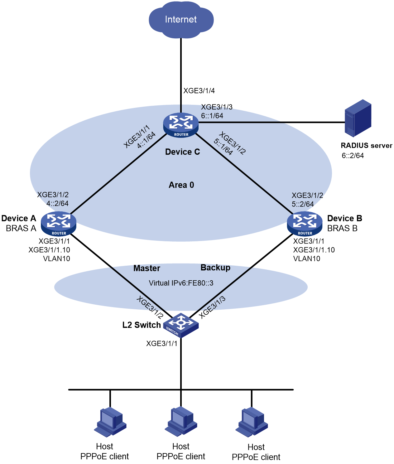
Procedure
1. Assign IP addresses to interfaces, as shown in Figure 6. (Details not shown.)
2. Configure the RADIUS server (this example uses a FreeRADIUS server that runs on Linux):
# Add the NAS IP address and shared key configuration to the clients.conf configuration file. (The NAS IP addresses for the two clients are 4::2, and 5::2, respectively, and the shared key is 123456.)
client 3::3/64 {
ipaddr = 3::3
netmask=64
secret=123456
}
client 4::2/64 {
ipaddr = 4::2
netmask=64
secret=123456
}
client 5::2/64 {
ipaddr = 5::2
netmask=64
secret=123456
}
# Add the PPPoE client configuration to the users file. (The usernames of the three PPPoE clients are user1, user2, and user3. The password is 123456.)
user1 Cleartext-Password :="123456"
user2 Cleartext-Password :="123456"
user3 Cleartext-Password :="123456"
3. Configure BRAS A:
a. Configure a RADIUS scheme:
# Create a RADIUS scheme named rs1 and enter RADIUS scheme view.
<BRASA> system-view
[BRASA] radius scheme rs1
# Specify the primary authentication server and primary accounting server.
[BRASA-radius-rs1] primary authentication ipv6 6::2
[BRASA-radius-rs1] primary accounting ipv6 6::2
# Set the shared key for secure RADIUS authentication and accounting communication.
[BRASA-radius-rs1] key authentication simple 123456
[BRASA-radius-rs1] key accounting simple 123456
# Configure the accounting-on feature for RADIUS scheme named rs1.
[BRASA-radius-rs1] accounting-on enable
# Specify the source IP address as 3::3 (the gateway address for the hosts) for outgoing RADIUS packets.
[BRASA-radius-rs1] nas-ip ipv6 3::3
[BRASA-radius-rs1] quit
b. Configure a prefix pool:
# Create prefix pool 1, and specify the prefix 3::/32 with the assigned prefix length 64. Prefix pool 1 contains 4294967296 prefixes from 3::/64 to 3:0:FFFF:FFFF::/64.
[BRASA] ipv6 dhcp prefix-pool 1 prefix 3::/32 assign-len 64
# Create IPv6 address pool pppoev6.
[BRASA] ipv6 pool pppoev6
# Apply prefix pool 1 to IPv6 address pool pppoev6.
[BRASA-ipv6-pool-pppoev6] prefix-pool 1 export-route
# Associate IPv6 address pool pppoev6 with VSRP instance vs1.
[BRASA-ipv6-pool-pppoev6] vsrp-instance vs1
[BRASA-ipv6-pool-pppoev6] quit
c. Configure an authentication domain:
# Create ISP domain dm1 and enter ISP domain view.
[BRASA] domain name dm1
# Configure the domain to use RADIUS scheme rs1 for authentication, authorization, and accounting for PPP users.
[BRASA-isp-dm1] authentication ppp radius-scheme rs1
[BRASA-isp-dm1] authorization ppp radius-scheme rs1
[BRASA-isp-dm1] accounting ppp radius-scheme rs1
# Specify the prefix pool and primary and secondary DNS server addresses for users in the ISP domain.
[BRASA-isp-dm1] authorization-attribute ipv6-nd-prefix-pool pppoev6
[BRASA-isp-dm1] authorization-attribute primary-dns ipv6 8::8
[BRASA-isp-dm1] authorization-attribute secondary-dns ipv6 8::8
[BRASA-isp-dm1] quit
d. Configure an IPv6 subnet route for PPP:
|
|
NOTE: · By default, in a VSRP environment, the master and backup BRAS devices both require configuring the ppp ipv6 route 3::/32 vsrp-instance vs1 command. Only the master device generates the static route for subnet 3::/32. When the master devices changes to backup device, the generated static route will be deleted. · The master device uses OSPFv3 to redistribute the static route generated by the ppp ipv6 route 3::/32 vsrp-instance vs1 configuration, and advertise the route to uplink Device C. Device C can then distribute all traffic destined for the subnet to the master BRAS device. |
# Configure PPP to add IPv6 subnet route 3::/32, and bind it to VSRP instance vs1.
[BRASA] ppp ipv6 route 3::/32 vsrp-instance vs1
e. Configure OSPFv3:
# Enable OSPFv3 process 1 and specify Area 0 on Loopback 0.
[BRASA] interface loopback 0
[BRASA-LoopBack0] ospfv3 1 area 0
# Set the OSPFv3 cost to 30 for Loopback 0 for the RADIUS server to choose the route to Loopback 0 based on the cost.
[BRASA-LoopBack0] ospfv3 cost 30
[BRASA-LoopBack0] quit
# Enable OSPFv3 process 1 and specify its router ID as 3.3.3.1.
[BRASA] ospfv3
[BRASA-ospfv3-1] router-id 3.3.3.1
# Configure OSPFv3 to redistribute the user network route filtered by routing policy 1. BRAS A then advertises the user network route destined for the subnet where the host resides to Device C. In this way, Device C can select the route to the host based on the state of BRAS A and BRAS B in the VSRP instance.
[BRASA-ospfv3-1] import-route unr inherit-cost route-policy 1
[BRASA-ospfv3-1] quit
# Configure routing policy 1 to permit routes destined for 3::/32.
[BRASA] ipv6 prefix-list 1 permit 3:: 32
[BRASA] route-policy 1 permit node 1
[BRASA-route-policy-1-1] if-match ipv6 address prefix-list 1
[BRASA-route-policy-1-1] quit
# Configure Area 0 on Ten-GigabitEthernet 3/1/2.
[BRASA] interface ten-gigabitethernet 3/1/2
[BRASA–Ten-GigabitEthernet3/1/2] ospfv3 1 area 0
[BRASA–Ten-GigabitEthernet3/1/2] quit
f. Configure an IPv6 VRRP group:
# Enter the view of Ten-GigabitEthernet 3/1/1.10.
[BRASA] interface ten-gigabitethernet 3/1/1.10
# Create IPv6 VRRP group 1 and set its virtual IP address to fe80::3.
[BRASA–Ten-GigabitEthernet3/1/1.10] vrrp ipv6 vrid 1 virtual-ip fe80::3 link-local
# Configure Ten-GigabitEthernet 3/1/1.10 to automatically generate a link-local address.
[BRASA–Ten-GigabitEthernet3/1/1.10] ipv6 address auto link-local
# Set the delay time for the IPv6 VRRP group to transition from Initialize to Master or Backup state to 50 seconds.
[BRASA–Ten-GigabitEthernet3/1/1.10] vrrp ipv6 state-transition-delay 50
# Set the priority of BRAS A to 250 in VRRP group 1 on Ten-GigabitEthernet 3/1/1.10. BRAS A is assigned a higher priority than BRAS B in VRRP group 1, so BRAS A can become the master.
[BRASA-Ten-GigabitEthernet3/1/1.10] vrrp ipv6 vrid 1 priority 250
# Configure BRAS A to operate in preemptive mode, and set the preemption delay to 90000 centiseconds (15 minutes). When the original master recovers, it has 15 minutes to synchronize data from the new master before switch-back to ensure stability and data consistency of the VRRP group.
[BRASA–Ten-GigabitEthernet3/1/1.10] vrrp ipv6 vrid 1 preempt-mode delay 90000
[BRASA–Ten-GigabitEthernet3/1/1.10] quit
# Create track entry 1 to monitor the link status of uplink interface Ten-GigabitEthernet 3/1/2. When the uplink fails, the track entry transits to Negative state.
[BRASA] track 1 interface ten-gigabitethernet 3/1/2
[BRASA-track-1] quit
# Associate VRRP group 1 on Ten-GigabitEthernet 3/1/1.10 with track entry 1 and decrease the device priority by 200 when the state of track entry 1 changes to Negative.
[BRASA] interface ten-gigabitethernet 3/1/1.10
[BRASA-Ten-GigabitEthernet3/1/1.10] vrrp ipv6 vrid 1 track 1 priority reduced 200
# Configure Ten-GigabitEthernet 3/1/1.10 to terminate VLAN 10.
[BRASA-Ten-GigabitEthernet3/1/1.10] vlan-type dot1q vid 10
[BRASA-Ten-GigabitEthernet3/1/1.10] quit
g. Configure a VSRP instance:
# Create VSRP group pr1 and enter VSRP peer view.
[BRASA] vsrp peer pr1
# Specify the local IP address as 4::2 and the peer IP address as 5::2 for VSRP to establish VSRP channels. The default TCP port number for the control channel is used.
[BRASA-vsrp-peer-pr1] peer ipv6 5::2 local 4::2
[BRASA-vsrp-peer-pr1] quit
# Create VSRP instance vs1 and enter its view.
[BRASA] vsrp instance vs1
# Associate VSRP instance vs1 with VSRP group pr1 and set its backup ID to 1.
[BRASA-vsrp-instance-vs1] backup id 1 peer pr1
# Bind VSRP instance vs1 to IPv6 VRRP group 1 on Ten-GigabitEthernet 3/1/1.10.
[BRASA-vsrp-instance-vs1] bind vrrp ipv6 vrid 1 interface Ten-GigabitEthernet3/1/1.10
# Specify the logical host name as abc.
[BRASA-vsrp-instance-vs1] nas id abc
# Specify the logical interface as Ten-GigabitEthernet 3/1/2.
[BRASA-vsrp-instance-vs1] nas port ten-gigabitethernet 3/1/2
[BRASA-vsrp-instance-vs1] quit
h. Configure PPPoE:
# Create interface Virtual-Template 1.
[BRASA] interface virtual-template 1
# Enable PAP authentication on Virtual-Template 1.
[BRASA-Virtual-Template1] ppp authentication-mode pap domain default enable dm1
[BRASA-Virtual-Template1] quit
# Enable a PPPoE server on Ten-GigabitEthernet 3/1/1, and bind the interface to Virtual-Template 1.
[BRASA] interface ten-gigabitethernet 3/1/1
[BRASA-Ten-GigabitEthernet3/1/1] pppoe-server bind virtual-template 1
# Associate Ten-GigabitEthernet 3/1/1 with VSRP instance vs1.
[BRASA-Ten-GigabitEthernet3/1/1] bras vsrp-instance vs1
# Configure Ten-GigabitEthernet 3/1/1 to automatically generate a link-local address, and disable RA message suppression.
[BRASA-Ten-GigabitEthernet3/1/1] ipv6 address auto link-local
[BRASA-Ten-GigabitEthernet3/1/1] undo ipv6 nd ra halt
# Specify a virtual IPv6 address of fe80::fffe for the interface, and bind it to VSRP instance vs1.
[BRASA–Ten-GigabitEthernet3/1/1] ipv6 virtual-address fe80::fffe vsrp vs1
# Enable DHCPv6 server, and associate the interface with VSRP instance vs1.
[BRASA-Ten-GigabitEthernet3/1/1] ipv6 dhcp select server
[BRASA-Ten-GigabitEthernet3/1/1] ipv6 dhcp vsrp-instance vs1
[BRASA-Ten-GigabitEthernet3/1/1] quit
4. Configure BRAS B:
a. Configure a RADIUS scheme:
# Create a RADIUS scheme named rs1 and enter RADIUS scheme view.
<BRASB> system-view
[BRASB] radius scheme rs1
# Specify the primary authentication server and primary accounting server.
[BRASB-radius-rs1] primary authentication ipv6 6::2
[BRASB-radius-rs1] primary accounting ipv6 6::2
# Set the shared key for secure RADIUS authentication and accounting communication.
[BRASB-radius-rs1] key authentication simple 123456
[BRASB-radius-rs1] key accounting simple 123456
# Configure the accounting-on feature for RADIUS scheme named rs1 (required for interoperation with iMC, and optional in other situations).
[BRASB-radius-rs1] accounting-on enable
# Specify the source IP address as 3::3 (the gateway address for hosts) for outgoing RADIUS packets.
[BRASB-radius-rs1] nas-ip ipv6 3::3
[BRASB-radius-rs1] quit
b. Configure a prefix pool:
# Create prefix pool 1, and specify the prefix 3::/32 with the assigned prefix length 64. Prefix pool 1 contains 4294967296 prefixes from 3::/64 to 3:0:FFFF:FFFF::/64.
[BRASB] ipv6 dhcp prefix-pool 1 prefix 3::/32 assign-len 64
# Create IPv6 address pool pppoev6.
[BRASB] ipv6 pool pppoev6
# Apply prefix pool 1 to IPv6 address pool pppoev6.
[BRASB-ipv6-pool-pppoev6] prefix-pool 1 export-route
# Associate IPv6 address pool pppoev6 with VSRP instance vs1.
[BRASB-ipv6-pool-pppoev6] vsrp-instance vs1
[BRASB-ipv6-pool-pppoev6] quit
c. Configure an authentication domain:
# Create ISP domain dm1 and enter ISP domain view.
[BRASB] domain name dm1
# Configure the domain to use RADIUS scheme rs1 for authentication, authorization, and accounting for PPP users.
[BRASB-isp-dm1] authentication ppp radius-scheme rs1
[BRASB-isp-dm1] authorization ppp radius-scheme rs1
[BRASB-isp-dm1] accounting ppp radius-scheme rs1
# Specify the prefix pool and primary and secondary DNS server addresses for users in the ISP domain.
[BRASB-isp-dm1] authorization-attribute ipv6-nd-prefix-pool pppoev6
[BRASB-isp-dm1] authorization-attribute primary-dns ipv6 8::8
[BRASB-isp-dm1] authorization-attribute secondary-dns ipv6 8::9
[BRASB-isp-dm1] quit
d. Configure an IPv6 subnet route for PPP:
|
|
NOTE: · By default, in a VSRP environment, the master and backup BRAS devices both require configuring the ppp ipv6 route 3::/32 vsrp-instance vs1 command. Only the master device generates the static route for subnet 3::/32. When the master devices changes to backup device, the generated static route will be deleted. · The master device uses OSPFv3 to redistribute the static route generated by the ppp ipv6 route 3::/32 vsrp-instance vs1 configuration, and advertise the route to uplink Device C. Device C can then distribute all traffic destined for the subnet to the master BRAS device. |
# Configure PPP to add IPv6 subnet route 3::/32, and bind it to VSRP instance vs1.
[BRASB] ppp ipv6 route 3::/32 vsrp-instance vs1
e. Configure OSPFv3:
# Enable OSPFv3 process 1 and specify Area 0 on Loopback 0.
[BRASB] interface loopback 0
[BRASB-LoopBack0] ospfv3 1 area 0
# Set the OSPFv3 cost to 30 for Loopback 0 for the RADIUS server to choose the route to Loopback 0 based on the cost.
[BRASB-LoopBack0] ospfv3 cost 30
[BRASB-LoopBack0] quit
# Enable OSPFv3 process 1 and specify its router ID as 3.3.3.2.
[BRASB] ospfv3
[BRASB-ospfv3-1] router-id 3.3.3.2
# Configure OSPFv3 to redistribute the user network route filtered by routing policy 1. BRAS B then advertises the user network route destined for the subnet where the host resides to Device C. In this way, Device C can select the route to the host based on the state of BRAS A and BRAS B in the VSRP instance.
[BRASB-ospfv3-1] import-route unr inherit-cost route-policy 1
[BRASB-ospfv3-1] quit
# Configure routing policy 1 to permit routes destined for 3::/32.
[BRASB] ipv6 prefix-list 1 permit 3:: 32
[BRASB] route-policy 1 permit node 1
[BRASB-route-policy-1-1] if-match ipv6 address prefix-list 1
[BRASB-route-policy-1-1] quit
# Configure Area 0 on Ten-GigabitEthernet 3/1/2.
[BRASB] interface ten-gigabitethernet 3/1/2
[BRASB–Ten-GigabitEthernet3/1/2] ospfv3 1 area 0
[BRASB–Ten-GigabitEthernet3/1/2] quit
f. Configure an IPv6 VRRP group:
# Enter the view of Ten-GigabitEthernet 3/1/1.10.
[BRASB] interface ten-gigabitethernet 3/1/1.10
# Create IPv6 VRRP group 1 and set its virtual IP address to fe80::3.
[BRASB–Ten-GigabitEthernet3/1/1.10] vrrp ipv6 vrid 1 virtual-ip fe80::3 link-local
# Configure Ten-GigabitEthernet 3/1/1.10 to automatically generate a link-local address.
[BRASB–Ten-GigabitEthernet3/1/1.10] ipv6 address auto link-local
# Set the priority of BRAS B to 200 in VRRP group 1 on Ten-GigabitEthernet 3/1/1.10. BRAS A is assigned a higher priority than BRAS B in VRRP group 1, so BRAS A can become the master.
[BRASB-Ten-GigabitEthernet3/1/1.10] vrrp ipv6 vrid 1 priority 200
# Configure BRAS B to operate in preemptive mode without setting the preemption delay. When the priority of the master decreases in the VRRP group, the backup can immediately take over as the new master for service continuity.
[BRASB–Ten-GigabitEthernet3/1/1.10] vrrp ipv6 vrid 1 preempt-mode
# Configure Ten-GigabitEthernet 3/1/1.10 to terminate VLAN 10.
[BRASB-Ten-GigabitEthernet3/1/1.10] vlan-type dot1q vid 10
[BRASB–Ten-GigabitEthernet3/1/1.10] quit
g. Configure a VSRP instance:
# Create VSRP group pr1 and enter VSRP peer view.
[BRASB] vsrp peer pr1
# Specify the local IP address as 5::2 and the peer IP address as 4::2 for VSRP to establish VSRP channels. The default TCP port number for the control channel is used.
[BRASB-vsrp-peer-pr1] peer ipv6 4::2 local 5::2
[BRASB-vsrp-peer-pr1] quit
# Create VSRP instance vs1 and enter its view.
[BRASB] vsrp instance vs1
# Associate VSRP instance vs1 with VSRP group pr1 and set its backup ID to 1.
[BRASB-vsrp-instance-vs1] backup id 1 peer pr1
# Bind VSRP instance vs1 to IPv6 VRRP group 1 on Ten-GigabitEthernet 3/1/1.10.
[BRASB-vsrp-instance-vs1] bind vrrp ipv6 vrid 1 interface Ten-GigabitEthernet3/1/1.10
# Specify the logical host name as abc.
[BRASB-vsrp-instance-vs1] nas id abc
# Specify the logical interface as Ten-GigabitEthernet 3/1/2.
[BRASB-vsrp-instance-vs1] nas port ten-gigabitethernet 3/1/2
[BRASB-vsrp-instance-vs1] quit
h. Configure PPPoE:
# Create interface Virtual-Template 1.
[BRASB] interface virtual-template 1
# Enable PAP authentication on Virtual-Template 1.
[BRASB-Virtual-Template1] ppp authentication-mode pap domain dm1
[BRASB-Virtual-Template1] quit
# Enable a PPPoE server on Ten-GigabitEthernet 3/1/1, and bind the interface to Virtual-Template 1.
[BRASB] interface ten-gigabitethernet 3/1/1
[BRASB-Ten-GigabitEthernet3/1/1] pppoe-server bind virtual-template 1
# Associate Ten-GigabitEthernet 3/1/1 with VSRP instance vs1.
[BRASB-Ten-GigabitEthernet3/1/1] bras vsrp-instance vs1
# Configure Ten-GigabitEthernet 3/1/1 to automatically generate a link-local address, and disable RA message suppression.
[BRASB-Ten-GigabitEthernet3/1/1] ipv6 address auto link-local
[BRASB-Ten-GigabitEthernet3/1/1] undo ipv6 nd ra halt
# Specify a virtual IPv6 address of fe80::fffe for the interface, and bind it to VSRP instance vs1.
[BRASB–Ten-GigabitEthernet3/1/1] ipv6 virtual-address fe80::fffe vsrp vs1
# Enable DHCPv6 server, and associate the interface with VSRP instance vs1.
[BRASB-Ten-GigabitEthernet3/1/1] ipv6 dhcp select server
[BRASB-Ten-GigabitEthernet3/1/1] ipv6 dhcp vsrp-instance vs1
[BRASB-GigabitEthernet1/0/1] quit
5. Configure Device C:
# Enable OSPFv3 process 1 and set its router ID to 6.6.6.1.
<DeviceC> system-view
[DeviceC] ospfv3
[DeviceC-ospfv3-1] router-id 6.6.6.1
[DeviceC-ospfv3-1] quit
# Configure Area 0.
[DeviceC] interface ten-gigabitethernet 3/1/1
[DeviceC–Ten-GigabitEthernet3/1/1] ospfv3 1 area 0
[DeviceC–Ten-GigabitEthernet3/1/1] quit
[DeviceC] interface ten-gigabitethernet 3/1/2
[DeviceC–Ten-GigabitEthernet3/1/2] ospfv1 1 area 0
[DeviceC–Ten-GigabitEthernet3/1/2] quit
[DeviceC] interface ten-gigabitethernet 3/1/3
[DeviceC-Ten-GigabitEthernet3/1/3] ospfv3 1 area 0
[DeviceC-Ten-GigabitEthernet3/1/3] quit
6. Configure L2 Switch:
# Create VLAN 10.
<L2Switch> system-view
[L2Switch] vlan 10
[L2Switch-vlan10] quit
# Assign Ten-GigabitEthernet 3/1/2 to VLAN 10.
[L2Switch] interface ten-gigabitethernet 3/1/2
[L2Switch-Ten-GigabitEthernet3/1/2] port link-type trunk
[L2Switch-Ten-GigabitEthernet3/1/2] port trunk permit vlan 10
[L2Switch-Ten-GigabitEthernet3/1/2] quit
# Assign Ten-GigabitEthernet 3/1/3 to VLAN 10.
[L2Switch] interface ten-gigabitethernet 3/1/3
[L2Switch-Ten-GigabitEthernet3/1/3] port link-type trunk
[L2Switch-Ten-GigabitEthernet3/1/3] port trunk permit vlan 10
[L2Switch-Ten-GigabitEthernet3/1/3] quit
Verifying the configuration
1. Enter username user1 and password 123456 on the PPPoE client software to initiate a connection request to the PPPoE server.
2. Verify that BRAS A (the master) and BRAS B (the backup) have the same access user information after the client accesses the network.
# Display access user information synchronized by VSRP instances on BRAS A.
[BRASA] display access-user
UserID Interface IP address MAC address S-/C-VLAN
Username Access type
IPv6 address
0x1 XGE3/1/1 - 001b-21a8-0949 -/-
user1 PPPoE users
3::4C0B:9D77:3D96:F2B
# Display access user information synchronized by VSRP instances on BRAS B.
[BRASB] display access-user
UserID Interface IP address MAC address S-/C-VLAN
Username Access type
IPv6 address
0x1 XGE3/1/1 - 001b-21a8-0949 -/-
user1 PPPoE users
3::4C0B:9D77:3D96:F2B
3. Verify that BRAS B becomes the master and takes over the PPPoE services when BRAS A fails (for example, Ten-GigabitEthernet 3/1/2 is down).
# Display access user information synchronized by VSRP instances on BRAS B.
[BRASB] display access-user
UserID Interface IP address MAC address S-/C-VLAN
Username Access type
IPv6 address
0x1 XGE3/1/1 - 001b-21a8-0949 -/-
user1 PPPoE users
3::4C0B:9D77:3D96:F2B
Example: Configuring VSRP for dual-stack PPPoE (IPv4 address pool and NDRA one prefix per user)
Network configuration
As shown in Figure 7, the hosts run PPPoE client dialup software. To ensure service availability, enable VSRP for PPPoE on BRAS A (the master PPPoE server) and BRAS B (the backup PPPoE server). When BRAS A fails, BRAS B takes over the PPPoE services to avoid service interruption. Perform the following tasks:
· Configure an IPv4 address pool for IPv4 address assignment on the BRAS devices.
· Configure NDRA for IPv6 address assignment on the BRAS devices. With NDRA configured, a host obtains an IPv6 prefix in an RA message. The host then generates an IPv6 global unicast address by combining the IPv6 prefix and the negotiated IPv6 interface identifier. The IPv6 prefix in the RA message is from a prefix pool.
· Create VRRP group 1 on Ten-GigabitEthernet 3/1/1.10, and configure the subinterface to terminate VLAN-tagged packets whose outermost VLAN ID is 10. (In a dual-stack network scenario, you can deploy either an IPv4 VRRP group or an IPv6 VRRP group. You only need to configure one of them, but make sure the configuration is consistent with the VSRP channel, that is, either IPv4 or IPv6 configuration.)
· Enable OSPF on BRAS A and BRAS B to ensure that they can learn and advertise routes on their uplinks.
· Enable VSRP for PPPoE to back up PPPoE sessions in real time.
· Use the RADIUS server for authentication, authorization, and accounting of PPPoE users.
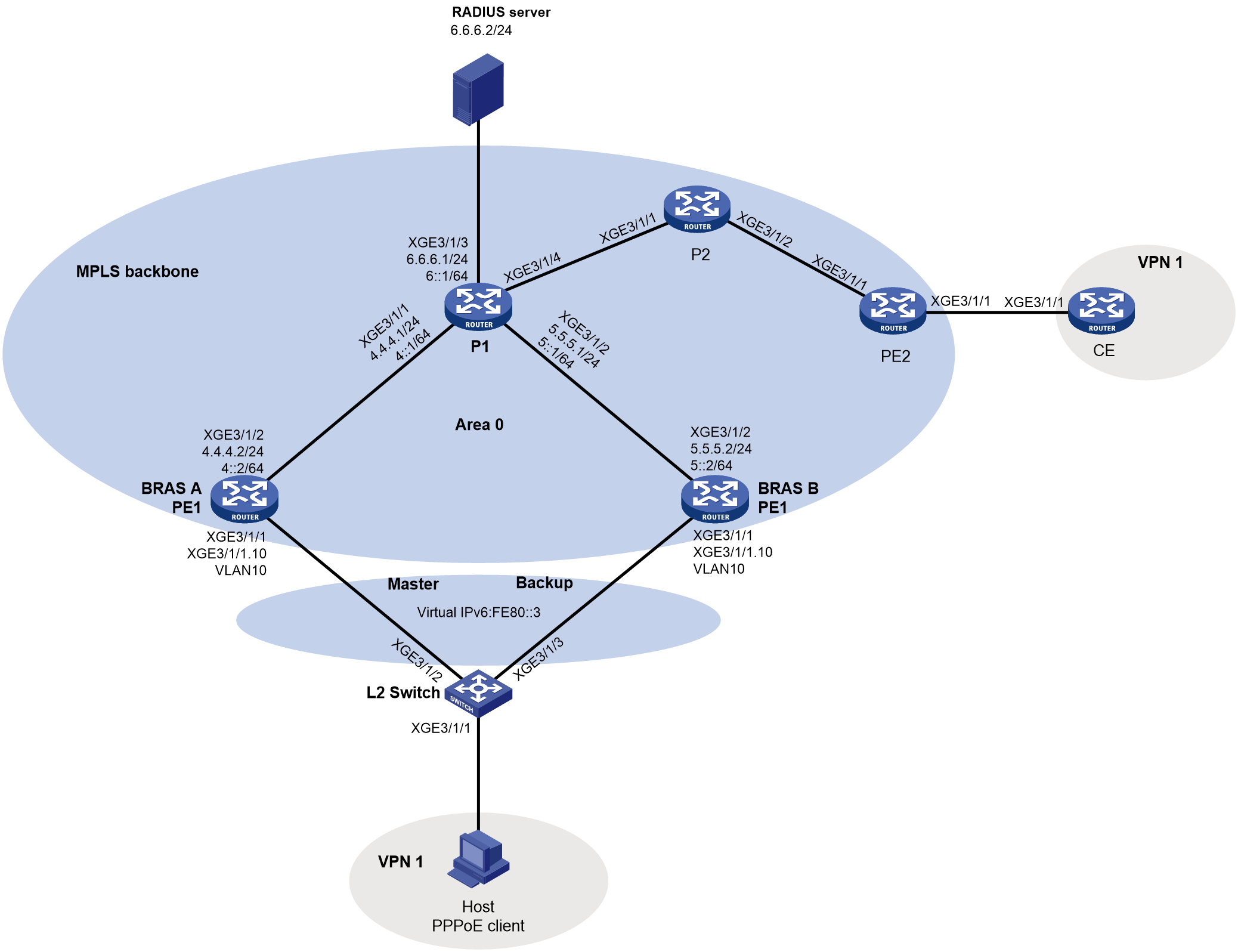
Procedure
1. Assign IP addresses to interfaces, as shown in Figure 7. (Details not shown.)
2. Configure the RADIUS server (this example uses a FreeRADIUS server that runs on Linux):
# Add the NAS IP address and shared key configuration to the clients.conf configuration file. (The NAS IP addresses for the two clients are 4.4.4.2, and 5.5.5.2, respectively, and the shared key is 123456.)
client 3.3.3.3/32 {
ipaddr = 3.3.3.3
netmask=32
secret=123456
}
client 4.4.4.2/32 {
ipaddr = 4.4.4.2
netmask=32
secret=123456
}
client 5.5.5.2/32 {
ipaddr = 5.5.5.2
netmask=24
secret=123456
}
# Add the PPPoE client configuration to the users file. (The usernames of the three PPPoE clients are user1, user2, and user3. The password is 123456.)
user1 Cleartext-Password :="123456"
user2 Cleartext-Password :="123456"
user3 Cleartext-Password :="123456"
3. Configure the DHCPv4 server:
|
|
NOTE: This example uses a network device as the DHCPv4 server. As a best practice, use a dedicated DHCPv4 server. |
# Enable DHCP.
<DHCP> system-view
[DHCP] dhcp enable
# Create IPv4 address pool pppoev4 and enter its view.
[DHCP] ip pool pppoev4
# Assign subnet 3.3.3.0/24 to the hosts, and specify the gateway address and DNS server address.
[DHCP-ip-pool-pppoev4] network 3.3.3.0 24
[DHCP-ip-pool-pppoev4] gateway-list 3.3.3.3
[DHCP-ip-pool-pppoev4] dns-list 8.8.8.8
# Exclude the gateway address and the IP addresses of host-facing interfaces on the BRAS devices from dynamic allocation.
[DHCP-ip-pool-pppoev4] forbidden-ip 3.3.3.1
[DHCP-ip-pool-pppoev4] forbidden-ip 3.3.3.2
[DHCP-ip-pool-pppoev4] forbidden-ip 3.3.3.3
[DHCP-ip-pool-pppoev4] quit
# Configure a static route for the DHCPv4 server to reach the BRAS devices.
[DHCP] ip route-static 0.0.0.0 0 6.6.6.1
4. Configure BRAS A:
a. Configure a RADIUS scheme:
# Create a RADIUS scheme named rs1 and enter RADIUS scheme view.
<BRASA> system-view
[BRASA] radius scheme rs1
# Specify the primary authentication server and primary accounting server.
[BRASA-radius-rs1] primary authentication 6.6.6.2
[BRASA-radius-rs1] primary accounting 6.6.6.2
# Set the shared key for secure RADIUS authentication and accounting communication.
[BRASA-radius-rs1] key authentication simple 123456
[BRASA-radius-rs1] key accounting simple 123456
# Specify the source IP address as 3.3.3.3 (the gateway address for the hosts) for outgoing RADIUS packets.
[BRASA-radius-rs1] nas-ip 3.3.3.3
[BRASA-radius-rs1] quit
b. Configure a remote BAS IPv4 address pool:
# Enable DHCP.
[BRASA] dhcp enable
# Configure remote BAS IPv4 address pool pppoev4 and associate the pool with VSRP instance vs1.
[BRASA] ip pool pppoev4 bas remote
[BRASA-ip-pool-pppoev4] gateway 3.3.3.3 24
[BRASA-ip-pool-pppoev4] forbidden-ip 3.3.3.3
[BRASA-ip-pool-pppoev4] remote-server 6.6.6.3
[BRASA-ip-pool-pppoev4] vsrp-instance vs1
# Configure BRASA acting as the VSRP master device to export the UNR of subnet 3.3.3.0/24 to the routing table, so that it can use OSPF to redistribute the UNR and advertise it to uplink Device C. Device C can then distribute all traffic destined for the subnet to the master BRAS device.
|
|
NOTE: · By default, in a VSRP environment, the master and backup BRAS devices both require configuring the network 3.3.3.0 24 export-route command. Only the master device exports the corresponding subnet route. When the master devices changes to backup device, the exported subnet route will be deleted. · The BRAS device in this example also acts as a DHCPv4 relay agent. Configuring the network 3.3.3.0 24 export-route command is only for exporting user subnet route 3.3.3.0/24 to the routing table for implementing traffic distribution through OSPF. The configuration is not for address allocation purposes. |
[BRASA-ip-pool-pppoev4] network 3.3.3.0 24 export-route
[BRASA-ip-pool-pppoev4] quit
c. Configure a prefix pool:
# Create prefix pool 1, and specify the prefix 3::/32 with the assigned prefix length 64. Prefix pool 1 contains 4294967296 prefixes from 3::/64 to 3:0:FFFF:FFFF::/64.
[BRASA] ipv6 dhcp prefix-pool 1 prefix 3::/32 assign-len 64
# Create IPv6 address pool pppoev6.
[BRASA] ipv6 pool pppoev6
# Apply prefix pool 1 to IPv6 address pool pppoev6.
[BRASA-ipv6-pool-pppoev6] prefix-pool 1 export-route
# Associate IPv6 address pool pppoev6 with VSRP instance vs1.
[BRASA-ipv6-pool-pppoev6] vsrp-instance vs1
[BRASA-ipv6-pool-pppoev6] quit
d. Configure an authentication domain:
# Create ISP domain dm1 and enter ISP domain view.
[BRASA] domain name dm1
# Configure the domain to use RADIUS scheme rs1 for authentication, authorization, and accounting for PPP users.
[BRASA-isp-dm1] authentication ppp radius-scheme rs1
[BRASA-isp-dm1] authorization ppp radius-scheme rs1
[BRASA-isp-dm1] accounting ppp radius-scheme rs1
# Specify the IPv4 address pool, prefix pool, and primary and secondary DNS server addresses for users in the ISP domain.
[BRASA-isp-dm1] authorization-attribute ip-pool pppoev4
[BRASA-isp-dm1] authorization-attribute ipv6-nd-prefix-pool pppoev6
[BRASA-isp-dm1] authorization-attribute primary-dns ipv6 8::8
[BRASA-isp-dm1] authorization-attribute secondary-dns ipv6 8::9
[BRASA-isp-dm1] quit
e. Configure OSPF:
# Enable OSPF process 1 and specify its router ID as 3.3.3.1 (the IP address of Ten-GigabitEthernet 3/1/1.10).
[BRASA] ospf 1 router-id 3.3.3.1
# Configure OSPF to redistribute the user network route filtered by routing policy 1. When BRAS A acts as the master and assigns an IP address to a host, it advertises the user network route destined for the subnet where the host resides to Device C. In this way, Device C can select the route to the host based on the state of BRAS A and BRAS B in the VSRP instance.
[BRASA-ospf-1] import-route unr route-policy 1
[BRASA-ospf-1] quit
# Configure routing policy 1 to permit routes destined for 3.3.3.0/24.
[BRASA] ip prefix-list 1 permit 3.3.3.0 24
[BRASA] route-policy 1 permit node 1
[BRASA-route-policy-1-1] if-match ip address prefix-list 1
[BRASA-route-policy-1-1] quit
# Configure Area 0.
[BRASA] ospf
[BRASA-ospf-1] area 0.0.0.0
[BRASA-ospf-1-area-0.0.0.0] network 4.4.4.0 0.0.0.255
[BRASA-ospf-1-area-0.0.0.0] quit
[BRASA-ospf-1] quit
f. Configure an IPv6 subnet route for PPP:
|
|
NOTE: · By default, in a VSRP environment, the master and backup BRAS devices both require configuring the ppp ipv6 route 3::/32 vsrp-instance vs1 command. Only the master device generates the static route for subnet 3::/32. When the master devices changes to backup device, the generated static route will be deleted. · The master device uses OSPFv3 to redistribute the static route generated by the ppp ipv6 route 3::/32 vsrp-instance vs1 configuration, and advertise the route to uplink Device C. Device C can then distribute all traffic destined for the subnet to the master BRAS device. |
# Configure PPP to add IPv6 subnet route 3::/32, and bind it to VSRP instance vs1.
[BRASA] ppp ipv6 route 3::/32 vsrp-instance vs1
g. Configure OSPFv3:
# Enable OSPFv3 process 1 and specify its router ID as 3.3.3.1.
[BRASA] ospfv3
[BRASA-ospfv3-1] router-id 3.3.3.1
# Configure OSPFv3 to redistribute the user network route filtered by routing policy 1. BRAS A then advertises the user network route destined for the subnet where the host resides to Device C. In this way, Device C can select the route to the host based on the state of BRAS A and BRAS B in the VSRP instance.
[BRASA-ospfv3-1] import-route unr inherit-cost route-policy 1
[BRASA-ospfv3-1] quit
# Configure routing policy 1 to permit routes destined for 3::/32.
[BRASA] ipv6 prefix-list 1 permit 3:: 32
[BRASA] route-policy 1 permit node 1
[BRASA-route-policy-1-1] if-match ipv6 address prefix-list 1
[BRASA-route-policy-1-1] quit
# Configure Area 0 on Ten-GigabitEthernet 3/1/2.
[BRASA] interface ten-gigabitethernet 3/1/2
[BRASA–Ten-GigabitEthernet3/1/2] ospfv3 1 area 0
[BRASA–Ten-GigabitEthernet3/1/2] quit
h. Configure an IPv6 VRRP group:
# Enter the view of Ten-GigabitEthernet 3/1/1.10.
[BRASA] interface ten-gigabitethernet 3/1/1.10
# Create IPv6 VRRP group 1 and set its virtual IP address to fe80::3.
[BRASA–Ten-GigabitEthernet3/1/1.10] vrrp ipv6 vrid 1 virtual-ip fe80::3 link-local
# Configure Ten-GigabitEthernet 3/1/1.10 to automatically generate a link-local address.
[BRASA–Ten-GigabitEthernet3/1/1.10] ipv6 address auto link-local
# Set the priority of BRAS A to 250 in VRRP group 1 on Ten-GigabitEthernet 3/1/1.10. BRAS A is assigned a higher priority than BRAS B in VRRP group 1, so BRAS A can become the master.
[BRASA-Ten-GigabitEthernet3/1/1.10] vrrp ipv6 vrid 1 priority 250
# Set the delay time for the IPv6 VRRP group to transition from Initialize to Master or Backup state to 50 seconds.
[BRASA–Ten-GigabitEthernet3/1/1.10] vrrp ipv6 state-transition-delay 50
# Configure BRAS A to operate in preemptive mode, and set the preemption delay to 90000 centiseconds (15 minutes). When the original master recovers, it has 15 minutes to synchronize data from the new master before switch-back to ensure stability and data consistency of the VRRP group.
[BRASA–Ten-GigabitEthernet3/1/1.10] vrrp ipv6 vrid 1 preempt-mode delay 90000
[BRASA–Ten-GigabitEthernet3/1/1.10] quit
# Create track entry 1 to monitor the link status of uplink interface Ten-GigabitEthernet 3/1/2. When the uplink fails, the track entry transits to Negative state.
[BRASA] track 1 interface ten-gigabitethernet 3/1/2
[BRASA-track-1] quit
# Associate VRRP group 1 on Ten-GigabitEthernet 3/1/1.10 with track entry 1 and decrease the device priority by 200 when the state of track entry 1 changes to Negative.
[BRASA] interface ten-gigabitethernet 3/1/1.10
[BRASA-Ten-GigabitEthernet3/1/1.10] vrrp ipv6 vrid 1 track 1 priority reduced 200
# Configure Ten-GigabitEthernet 3/1/1.10 to terminate VLAN 10.
[BRASA-Ten-GigabitEthernet3/1/1.10] vlan-type dot1q vid 10
[BRASA-Ten-GigabitEthernet3/1/1.10] quit
i. Configure a VSRP instance:
|
|
NOTE: When VSRP is enabled for PPPoE, IPv4 and IPv6 users share a data backup channel. You can configure an IPv4 or IPv6 data backup channel for dual-stack PPPoE. This example creates an IPv6 data backup channel. |
# Create VSRP group pr1 and enter VSRP peer view.
[BRASA] vsrp peer pr1
# Specify the local IP address as 4::2 and the peer IP address as 5::2 for VSRP to establish VSRP channels. The default TCP port number for the control channel is used.
[BRASA-vsrp-peer-pr1] peer ipv6 5::2 local 4::2
[BRASA-vsrp-peer-pr1] quit
# Create VSRP instance vs1 and enter its view.
[BRASA] vsrp instance vs1
# Associate VSRP instance vs1 with VSRP group pr1 and set its backup ID to 1.
[BRASA-vsrp-instance-vs1] backup id 1 peer pr1
# Bind VSRP instance vs1 to IPv6 VRRP group 1 on Ten-GigabitEthernet 3/1/1.10.
[BRASA-vsrp-instance-vs1] bind vrrp ipv6 vrid 1 interface ten-gigabitethernet 3/1/1.10
# Specify the logical host name as abc.
[BRASA-vsrp-instance-vs1] nas id abc
# Specify the logical interface as Ten-GigabitEthernet 3/1/2.
[BRASA-vsrp-instance-vs1] nas port ten-gigabitethernet 3/1/2
[BRASA-vsrp-instance-vs1] quit
j. Configure PPPoE:
# Create interface Virtual-Template 1.
[BRASA] interface virtual-template 1
# Enable PAP authentication on Virtual-Template 1.
[BRASA-Virtual-Template1] ppp authentication-mode pap domain default enable dm1
[BRASA-Virtual-Template1] quit
# Enable a PPPoE server on Ten-GigabitEthernet 3/1/1, and bind the interface to Virtual-Template 1.
[BRASA] interface ten-gigabitethernet 3/1/1
[BRASA-Ten-GigabitEthernet3/1/1] pppoe-server bind virtual-template 1
# Associate Ten-GigabitEthernet 3/1/1 with VSRP instance vs1.
[BRASA-Ten-GigabitEthernet3/1/1] bras vsrp-instance vs1
# Configure Ten-GigabitEthernet 3/1/1 to automatically generate a link-local address, and disable RA message suppression.
[BRASA-Ten-GigabitEthernet3/1/1] ipv6 address auto link-local
[BRASA-Ten-GigabitEthernet3/1/1] undo ipv6 nd ra halt
# Specify a virtual IPv6 address of fe80::fffe for the interface, and bind it to VSRP instance vs1.
[BRASA-Ten-GigabitEthernet3/1/1] ipv6 virtual-address fe80::fffe vsrp vs1
# Enable DHCPv6 server, and associate the interface with VSRP instance vs1.
[BRASA-Ten-GigabitEthernet3/1/1] ipv6 dhcp select server
[BRASA-Ten-GigabitEthernet3/1/1] ipv6 dhcp vsrp-instance vs1
[BRASA-Ten-GigabitEthernet3/1/1] quit
5. Configure BRAS B:
a. Configure a RADIUS scheme:
# Create a RADIUS scheme named rs1 and enter RADIUS scheme view.
<BRASB> system-view
[BRASB] radius scheme rs1
# Specify the primary authentication server and primary accounting server.
[BRASB-radius-rs1] primary authentication 6.6.6.2
[BRASB-radius-rs1] primary accounting 6.6.6.2
# Set the shared key for secure RADIUS authentication and accounting communication.
[BRASB-radius-rs1] key authentication simple 123456
[BRASB-radius-rs1] key accounting simple 123456
# Specify the source IP address as 3.3.3.3 (the gateway address for hosts) for outgoing RADIUS packets.
[BRASB-radius-rs1] nas-ip 3.3.3.3
[BRASB-radius-rs1] quit
b. Configure a remote BAS IPv4 address pool:
# Enable DHCP.
[BRASB] dhcp enable
# Configure remote BAS IPv4 address pool pppoev4 and associate the pool with VSRP instance vs1.
[BRASB] ip pool pppoev4 bas remote
[BRASB-ip-pool-pppoev4] gateway 3.3.3.3 24
[BRASB-ip-pool-pppoev4] forbidden-ip 3.3.3.3
[BRASB-ip-pool-pppoev4] remote-server 6.6.6.3
[BRASB-ip-pool-pppoev4] vsrp-instance vs1
# Configure BRASB acting as the VSRP master device to export the UNR of subnet 3.3.3.0/24 to the routing table, so that it can use OSPF to redistribute the UNR and advertise it to uplink Device C. Device C can then distribute all traffic destined for the subnet to the master BRAS device.
|
|
NOTE: · By default, in a VSRP environment, the master and backup BRAS devices both require configuring the network 3.3.3.0 24 export-route command. Only the master device exports the corresponding subnet route. When the master devices changes to backup device, the exported subnet route will be deleted. · The BRAS device in this example also acts as a DHCPv4 relay agent. Configuring the network 3.3.3.0 24 export-route command is only for exporting user subnet route 3.3.3.0/24 to the routing table for implementing traffic distribution through OSPF. The configuration is not for address allocation purposes. |
[BRASB-ip-pool-pppoev4] network 3.3.3.0 24 export-route
[BRASB-ip-pool-pppoev4] quit
c. Configure a prefix pool:
# Create prefix pool 1, and specify the prefix 3::/32 with the assigned prefix length 64. Prefix pool 1 contains 4294967296 prefixes from 3::/64 to 3:0:FFFF:FFFF::/64.
[BRASB] ipv6 dhcp prefix-pool 1 prefix 3::/32 assign-len 64
# Create IPv6 address pool pppoev6.
[BRASB] ipv6 pool pppoev6
# Apply prefix pool 1 to IPv6 address pool pppoev6.
[BRASB-ipv6-pool-pppoev6] prefix-pool 1 export-route
# Associate IPv6 address pool pppoev6 with VSRP instance vs1.
[BRASB-ipv6-pool-pppoev6] vsrp-instance vs1
[BRASB-ipv6-pool-pppoev6] quit
d. Configure an authentication domain:
# Create ISP domain dm1 and enter ISP domain view.
[BRASB] domain name dm1
# Configure the domain to use RADIUS scheme rs1 for authentication, authorization, and accounting for PPP users.
[BRASB-isp-dm1] authentication ppp radius-scheme rs1
[BRASB-isp-dm1] authorization ppp radius-scheme rs1
[BRASB-isp-dm1] accounting ppp radius-scheme rs1
# Specify the IPv4 address pool, prefix pool, and primary and secondary DNS server addresses for users in the ISP domain.
[BRASB-isp-dm1] authorization-attribute ip-pool pppoev4
[BRASB-isp-dm1] authorization-attribute ipv6-nd-prefix-pool pppoev6
[BRASB-isp-dm1] authorization-attribute primary-dns ipv6 8::8
[BRASB-isp-dm1] authorization-attribute secondary-dns ipv6 8::9
[BRASB-isp-dm1] quit
e. Configure OSPF:
# Enable OSPF process 1 and specify its router ID as 3.3.3.2 (the IP address of Ten-GigabitEthernet 3/1/1.10).
[BRASB] ospf 1 router-id 3.3.3.2
# Configure OSPF to redistribute the user network route filtered by routing policy 1. BRAS B then advertises the user network route destined for the subnet where the host resides to Device C. In this way, Device C can select the route to the host based on the state of BRAS A and BRAS B in the VSRP instance.
[BRASB-ospf-1] import-route unr inherit-cost route-policy 1
[BRASB-ospf-1] quit
# Configure routing policy 1 to permit routes destined for 3.3.3.0/24.
[BRASB] ip prefix-list 1 permit 3.3.3.0 24
[BRASB] route-policy 1 permit node 1
[BRASB-route-policy-1-1] if-match ip address prefix-list 1
[BRASB-route-policy-1-1] quit
# Configure Area 0.
[BRASB] ospf
[BRASB-ospf-1] area 0.0.0.0
[BRASB-ospf-1-area-0.0.0.0] network 5.5.5.0 0.0.0.255
[BRASB-ospf-1-area-0.0.0.0] quit
[BRASB-ospf-1] quit
f. Configure an IPv6 subnet route for PPP:
|
|
NOTE: · By default, in a VSRP environment, the master and backup BRAS devices both require configuring the ppp ipv6 route 3::/32 vsrp-instance vs1 command. Only the master device generates the static route for subnet 3::/32. When the master devices changes to backup device, the generated static route will be deleted. · The master device uses OSPFv3 to redistribute the static route generated by the ppp ipv6 route 3::/32 vsrp-instance vs1 configuration, and advertise the route to uplink Device C. Device C can then distribute all traffic destined for the subnet to the master BRAS device. |
# Configure PPP to add IPv6 subnet route 3::/32, and bind it to VSRP instance vs1.
[BRASB] ppp ipv6 route 3::/32 vsrp-instance vs1
g. Configure OSPFv3:
# Enable OSPFv3 process 1 and specify its router ID as 3.3.3.2.
[BRASB] ospfv3
[BRASB-ospfv3-1] router-id 3.3.3.2
# Configure OSPFv3 to redistribute the user network route filtered by routing policy 1. BRAS B then advertises the user network route destined for the subnet where the host resides to Device C. In this way, Device C can select the route to the host based on the state of BRAS A and BRAS B in the VSRP instance.
[BRASB-ospfv3-1] import-route unr inherit-cost route-policy 1
[BRASB-ospfv3-1] quit
# Configure routing policy 1 to permit routes destined for 3::/32.
[BRASB] ipv6 prefix-list 1 permit 3:: 32
[BRASB] route-policy 1 permit node 1
[BRASB-route-policy-1-1] if-match ipv6 address prefix-list 1
[BRASB-route-policy-1-1] quit
# Configure Area 0 on Ten-GigabitEthernet 3/1/2.
[BRASB] interface ten-gigabitethernet 3/1/2
[BRASB–Ten-GigabitEthernet3/1/2] ospfv3 1 area 0
[BRASB–Ten-GigabitEthernet3/1/2] quit
h. Configure an IPv6 VRRP group:
# Enter the view of Ten-GigabitEthernet 3/1/1.10.
[BRASB] interface ten-gigabitethernet 3/1/1.10
# Create IPv6 VRRP group 1 and set its virtual IP address to fe80::3.
[BRASB–Ten-GigabitEthernet3/1/1.10] vrrp ipv6 vrid 1 virtual-ip fe80::3 link-local
# Configure Ten-GigabitEthernet 3/1/1.10 to automatically generate a link-local address.
[BRASB–Ten-GigabitEthernet3/1/1.10] ipv6 address auto link-local
# Set the priority of BRAS B to 200 in VRRP group 1 on Ten-GigabitEthernet 3/1/1.10. BRAS A is assigned a higher priority than BRAS B in VRRP group 1, so BRAS A can become the master.
[BRASB-Ten-GigabitEthernet3/1/1.10] vrrp ipv6 vrid 1 priority 200
# Configure BRAS B to operate in preemptive mode without setting the preemption delay. When the priority of the master decreases in the VRRP group, the backup can immediately take over as the new master for service continuity.
[BRASB–Ten-GigabitEthernet3/1/1.10] vrrp ipv6 vrid 1 preempt-mode
# Configure Ten-GigabitEthernet 3/1/1.10 to terminate VLAN 10.
[BRASB-Ten-GigabitEthernet3/1/1.10] vlan-type dot1q vid 10
[BRASB–Ten-GigabitEthernet3/1/1.10] quit
i. Configure the track entry associated with the BFD session on Ten-GigabitEthernet 3/1/1.10:
# Create track entry 2 and associate it with a BFD session.
[BRASB] track 2 bfd echo interface ten-gigabitethernet 3/1/1.10 remote ip 3.3.3.1 local ip 3.3.3.2
[BRASB-track-2] quit
# Associate VRRP group 1 on Ten-GigabitEthernet 3/1/1.10 with track entry 2 and switch the master and the backup when the state of track entry 2 changes to Negative.
[BRASB] interface ten-gigabitethernet 3/1/1.10
[BRASB–Ten-GigabitEthernet3/1/1.10] vrrp ipv6 vrid 1 track 2 switchover
[BRASB–Ten-GigabitEthernet3/1/1.10] quit
j. Configure a VSRP instance:
|
|
NOTE: When VSRP is enabled for PPPoE, IPv4 and IPv6 users share a data backup channel. You can configure an IPv4 or IPv6 data backup channel for dual-stack PPPoE. This example creates an IPv6 data backup channel. |
# Create VSRP group pr1 and enter VSRP peer view.
[BRASB] vsrp peer pr1
# Specify the local IP address as 5::2 and the peer IP address as 4::2 for VSRP to establish VSRP channels. The default TCP port number for the control channel is used.
[BRASB-vsrp-peer-pr1] peer ipv6 4::2 local 5::2
[BRASB-vsrp-peer-pr1] quit
# Create VSRP instance vs1 and enter its view.
[BRASB] vsrp instance vs1
# Associate VSRP instance vs1 with VSRP group pr1 and set its backup ID to 1.
[BRASB-vsrp-instance-vs1] backup id 1 peer pr1
# Bind VSRP instance vs1 to IPv6 VRRP group 1 on Ten-GigabitEthernet 3/1/1.10.
[BRASB-vsrp-instance-vs1] bind vrrp ipv6 vrid 1 interface ten-gigabitethernet 3/1/1.10
# Specify the logical host name as abc.
[BRASB-vsrp-instance-vs1] nas id abc
# Specify the logical interface as Ten-GigabitEthernet 3/1/2.
[BRASB-vsrp-instance-vs1] nas port ten-gigabitethernet 3/1/2
[BRASB-vsrp-instance-vs1] quit
k. Configure PPPoE:
# Create interface Virtual-Template 1.
[BRASB] interface virtual-template 1
# Enable PAP authentication on Virtual-Template 1.
[BRASB-Virtual-Template1] ppp authentication-mode pap domain default enable dm1
[BRASB-Virtual-Template1] quit
# Enable a PPPoE server on Ten-GigabitEthernet 3/1/1, and bind the interface to Virtual-Template 1.
[BRASB] interface ten-gigabitethernet 3/1/1
[BRASB-Ten-GigabitEthernet3/1/1] pppoe-server bind virtual-template 1
# Associate Ten-GigabitEthernet 3/1/1 with VSRP instance vs1.
[BRASB-Ten-GigabitEthernet3/1/1] bras vsrp-instance vs1
# Configure Ten-GigabitEthernet 3/1/1 to automatically generate a link-local address, and disable RA message suppression.
[BRASB-Ten-GigabitEthernet3/1/1] ipv6 address auto link-local
[BRASB-Ten-GigabitEthernet3/1/1] undo ipv6 nd ra halt
# Specify a virtual IPv6 address of fe80::fffe for the interface, and bind it to VSRP instance vs1.
[BRASB-Ten-GigabitEthernet3/1/1] ipv6 virtual-address fe80::fffe vsrp vs1
# Associate Ten-GigabitEthernet 3/1/1 with VSRP instance vs1.
[BRASB-Ten-GigabitEthernet3/1/1] dhcp relay vsrp-instance vs1
# Enable DHCPv6 server, and associate the interface with VSRP instance vs1.
[BRASB-Ten-GigabitEthernet3/1/1] ipv6 dhcp select server
[BRASB-Ten-GigabitEthernet3/1/1] ipv6 dhcp vsrp-instance vs1
[BRASB-Ten-GigabitEthernet3/1/1] quit
6. Configure Device C:
a. Configure OSPF:
# Enable OSPF process 1 and set its router ID to 6.6.6.1 (the IP address of Ten-GigabitEthernet 3/1/3).
<DeviceC> system-view
[DeviceC] ospf 1 router-id 6.6.6.1
# Configure Area 0.
[DeviceC-ospf-1] area 0.0.0.0
[DeviceC-ospf-1-area-0.0.0.0] network 4.4.4.0 0.0.0.255
[DeviceC-ospf-1-area-0.0.0.0] network 5.5.5.0 0.0.0.255
[DeviceC-ospf-1-area-0.0.0.0] quit
[DeviceC-ospf-1] quit
b. Configure OSPFv3:
# Enable OSPFv3 process 1 and set its router ID to 6.6.6.1.
<DeviceC> system-view
[DeviceC] ospfv3
[DeviceC-ospfv3-1] router-id 6.6.6.1
[DeviceC-ospfv3-1] quit
# Configure Area 0.
[DeviceC] interface ten-gigabitethernet 3/1/1
[DeviceC–Ten-GigabitEthernet3/1/1] ospfv3 1 area 0
[DeviceC–Ten-GigabitEthernet3/1/1] quit
[DeviceC] interface ten-gigabitethernet 3/1/2
[DeviceC–Ten-GigabitEthernet3/1/2] ospfv1 1 area 0
[DeviceC–Ten-GigabitEthernet3/1/2] quit
[DeviceC] interface ten-gigabitethernet 3/1/3
[DeviceC-Ten-GigabitEthernet3/1/3] ospfv3 1 area 0
[DeviceC-Ten-GigabitEthernet3/1/3] quit
7. Configure L2 Switch:
# Create VLAN 10.
<L2Switch> system-view
[L2Switch] vlan 10
[L2Switch-vlan10] quit
# Assign Ten-GigabitEthernet 3/1/2 to VLAN 10.
[L2Switch] interface ten-gigabitethernet 3/1/2
[L2Switch-Ten-GigabitEthernet3/1/2] port link-type trunk
[L2Switch-Ten-GigabitEthernet3/1/2] port trunk permit vlan 10
[L2Switch-Ten-GigabitEthernet3/1/2] quit
# Assign Ten-GigabitEthernet 3/1/3 to VLAN 10.
[L2Switch] interface ten-gigabitethernet 3/1/3
[L2Switch-Ten-GigabitEthernet3/1/3] port link-type trunk
[L2Switch-Ten-GigabitEthernet3/1/3] port trunk permit vlan 10
[L2Switch-Ten-GigabitEthernet3/1/3] quit
Verifying the configuration
1. Enter username user1 and password 123456 on the PPPoE client software to initiate a connection request to the PPPoE server.
2. Verify that BRAS A (the master) and BRAS B (the backup) have the same PPP and PPPoE sessions after the client accesses the network.
# Display PPP sessions synchronized by VSRP instances on BRAS A.
[BRASA] display access-user
UserID Interface IP address MAC address S-/C-VLAN
Username Access type
IPv6 address
0x1 XGE3/1/1 3.3.3.6 001b-21a8-0949 -/-
user1 PPPoE users
3::4C0B:9D77:3D96:F2B
# Display PPP sessions synchronized by VSRP instances on BRAS B.
[BRASB] display access-user
UserID Interface IP address MAC address S-/C-VLAN
Username Access type
IPv6 address
0x1 XGE3/1/1 3.3.3.6 001b-21a8-0949 -/-
user1 3::4C0B:9D77:3D96:F PPPoE users
2B
-
3. Verify that BRAS B becomes the master and takes over the PPPoE services when BRAS A fails (for example, Ten-GigabitEthernet 3/1/1 is down).
# Display PPP sessions synchronized by VSRP instances on BRAS B.
[BRASB] display access-user
UserID Interface IP address MAC address S-/C-VLAN
Username Access type
IPv6 address
0x1 XGE3/1/1 3.3.3.6 001b-21a8-0949 -/-
user1 PPPoE users
3::4C0B:9D77:3D96:F2B
Example: Configuring VSRP for dual-stack PPPoE (IPv4 address pool and IPv6 address pool for a VPN instance)
Network configuration
As shown in Figure 8, the hosts run PPPoE client dialup software. To ensure service availability, enable VSRP for PPPoE on BRAS A (the master PPPoE server) and BRAS B (the backup PPPoE server). When BRAS A fails, BRAS B takes over the PPPoE services to avoid service interruption. Perform the following tasks:
· Configure an IPv4 address pool and an IPv6 address pool for IP address assignment for uses in a VPN instance on the BRAS devices.
· Create VRRP group 1 on Ten-GigabitEthernet 3/1/1.10, and configure the subinterface to terminate VLAN-tagged packets whose outermost VLAN ID is 10.
· Enable OSPF on BRAS A and BRAS B to ensure that they can learn and advertise routes on their uplinks.
· Enable VSRP for PPPoE to back up PPPoE sessions in real time.
· Use the RADIUS server for authentication, authorization, and accounting of PPPoE users.

Prerequisites
Configure MPLS L3VPN before you configure PPPoE. Assign matching VPN targets to the sites of VPN 1 for the sites to communicate with each other. This example provides only access authentication configuration on PE 1. For more information about other MPLS L3VPN configuration, see MPLS Configuration Guide.
Procedure
1. Assign IP addresses to interfaces, as shown in Figure 8. (Details not shown.)
2. Configure the RADIUS server (this example uses a FreeRADIUS server that runs on Linux):
# Add the NAS IP address and shared key configuration to the clients.conf configuration file. (The NAS IP addresses for the two clients are 4.4.4.2, and 5.5.5.2, respectively, and the shared key is 123456.)
client 3.3.3.3/32 {
ipaddr = 3.3.3.3
netmask=32
secret=123456
}
client 4.4.4.2/32 {
ipaddr = 4.4.4.2
netmask=32
secret=123456
}
client 5.5.5.2/32 {
ipaddr = 5.5.5.2
netmask=24
secret=123456
}
# Add the PPPoE client configuration to the users file. (The username of the PPPoE client is user1. The password is 123456.)
user1 Cleartext-Password :="123456"
3. Configure BRAS A:
a. Create VPN instance vpn1.
<BRASA> system-view
[BRASA] ip vpn-instance vpn1
[BRASA-vpn-instance-vpn1] quit
b. Configure a RADIUS scheme:
# Create a RADIUS scheme named rs1 and enter RADIUS scheme view.
[BRASA] radius scheme rs1
# Specify the primary authentication server and primary accounting server.
[BRASA-radius-rs1] primary authentication 6.6.6.2
[BRASA-radius-rs1] primary accounting 6.6.6.2
# Set the shared key for secure RADIUS authentication and accounting communication.
[BRASA-radius-rs1] key authentication simple 123456
[BRASA-radius-rs1] key accounting simple 123456
# Specify the source IP address as 3.3.3.3 (the gateway address for the hosts) for outgoing RADIUS packets.
[BRASA-radius-rs1] nas-ip 3.3.3.3
[BRASA-radius-rs1] quit
c. Configure PBR:
|
|
NOTE: Configure static routes and PBR for the RADIUS packets sent by BRAS devices to reach the RADIUS server. |
# Configure a static route for users in VPN instance vpn1 to reach the RADIUS server.
[BRASA] ip route-static vpn-instance vpn1 6.6.6.2 32 4.4.4.1 public
# Configure ACL 3030 to match traffic with source address 6.6.6.2/32 and destination address 3.3.3.3/32.
[BRASA] acl advanced 3030
[BRASA-acl-ipv4-adv-3030] rule permit ip source 6.6.6.2 0 destination 3.3.3.3 0
[BRASA-acl-ipv4-adv-3030] quit
# Create PBR policy public_to_vpn1. Configure the policy to permit traffic that matches ACL 3030 in VPN instance vpn1.
[BRASA] policy-based-route public_to_vpn1 permit node 0
[BRASA-pbr-public_to_vpn1-0] if-match acl 3030
[BRASA-pbr-public_to_vpn1-0] apply access-vpn vpn-instance vpn1
[BRASA-pbr-public_to_vpn1-0] quit
# Apply PBR policy public_to_vpn1 to Ten-GigabitEthernet 3/1/2.
[BRASA] interface ten-gigabitethernet 3/1/2
[BRASA–Ten-GigabitEthernet3/1/2] ip policy-based-route public_to_vpn1
[BRASA–Ten-GigabitEthernet3/1/2] quit
d. Configure an IPv4 address pool:
# Enable DHCP.
[BRASA] dhcp enable
# Create IPv4 address pool pppoev4 and enter its view.
[BRASA] ip pool pppoev4
# Assign subnet 3.3.3.0/24 to the hosts, and specify the gateway address and DNS server address.
[BRASA-ip-pool-pppoev4] network 3.3.3.0 24 export-route
[BRASA-ip-pool-pppoev4] gateway-list 3.3.3.3 export-route
[BRASA-ip-pool-pppoev4] dns-list 8.8.8.8
# Exclude the gateway address and the IP addresses of host-facing interfaces on the BRAS devices from dynamic allocation.
[BRASA-ip-pool-pppoev4] forbidden-ip 3.3.3.1
[BRASA-ip-pool-pppoev4] forbidden-ip 3.3.3.2
[BRASA-ip-pool-pppoev4] forbidden-ip 3.3.3.3
# Associate the address pool with VSRP instance vs1 and VPN instance vpn1.
[BRASA-ip-pool-pppoev4] vsrp-instance vs1
[BRASA-ip-pool-pppoev4] vpn-instance vpn1
[BRASA-ip-pool-pppoev4] quit
e. Configure an IPv6 address pool:
# Create IPv6 address pool pppoev6. Assign subnet 3::/64 to the hosts and specify the DNS server address.
[BRASA] ipv6 pool pppoev6
[BRASA-ipv6-pool-pppoev6] network 3::/64 export-route
[BRASA-ipv6-pool-pppoev6] dns-server 8::8
# Associate the address pool with VSRP instance vs1 and VPN instance vpn1.
[BRASA-ipv6-pool-pppoev6] vsrp-instance vs1
[BRASA-ipv6-pool-pppoev6] vpn-instance vpn1
[BRASA-ipv6-pool-pppoev6] quit
# Exclude the gateway address and the IP addresses of host-facing interfaces on the BRAS devices from dynamic allocation.
[BRASA] ipv6 dhcp server forbidden-address 3::1 vpn-instance vpn1
[BRASA] ipv6 dhcp server forbidden-address 3::2 vpn-instance vpn1
[BRASA] ipv6 dhcp server forbidden-address 3::3 vpn-instance vpn1
f. Configure an authentication domain:
# Create ISP domain dm1 and enter ISP domain view.
[BRASA] domain name dm1
# Configure the domain to use RADIUS scheme rs1 for authentication, authorization, and accounting for PPP users.
[BRASA-isp-dm1] authentication ppp radius-scheme rs1
[BRASA-isp-dm1] authorization ppp radius-scheme rs1
[BRASA-isp-dm1] accounting ppp radius-scheme rs1
# Specify the IPv4 address pool, IPv6 address pool, and VPN instance for users in the ISP domain.
[BRASA-isp-dm1] authorization-attribute ip-pool pppoev4
[BRASA-isp-dm1] authorization-attribute ipv6-pool pppoev6
[BRASA-isp-dm1] authorization-attribute vpn-instance vpn1
[BRASA-isp-dm1] quit
g. Configure OSPF:
# Enable OSPF process 1 and specify its router ID as 3.3.3.1 (the IP address of Ten-GigabitEthernet 3/1/1.10).
[BRASA] ospf 1 router-id 3.3.3.1
# Configure Area 0.
[BRASA-ospf-1] area 0.0.0.0
[BRASA-ospf-1-area-0.0.0.0] network 4.4.4.0 0.0.0.255
[BRASA-ospf-1-area-0.0.0.0] quit
[BRASA-ospf-1] quit
h. Configure OSPFv3:
# Enable OSPFv3 process 1 and specify its router ID as 3.3.3.1.
[BRASA] ospfv3
[BRASA-ospfv3-1] router-id 3.3.3.1
[BRASA-ospfv3-1] quit
# Configure Area 0 on Ten-GigabitEthernet 3/1/2.
[BRASA] interface ten-gigabitethernet 3/1/2
[BRASA–Ten-GigabitEthernet3/1/2] ospfv3 1 area 0
[BRASA–Ten-GigabitEthernet3/1/2] quit
i. Configure an IPv6 VRRP group:
# Enter the view of Ten-GigabitEthernet 3/1/1.10.
[BRASA] interface ten-gigabitethernet 3/1/1.10
# Create IPv6 VRRP group 1 and set its virtual IP address to fe80::3.
[BRASA–Ten-GigabitEthernet3/1/1.10] vrrp ipv6 vrid 1 virtual-ip fe80::3 link-local
# Configure Ten-GigabitEthernet 3/1/1.10 to automatically generate a link-local address.
[BRASA–Ten-GigabitEthernet3/1/1.10] ipv6 address auto link-local
# Set the delay time for the IPv6 VRRP group to transition from Initialize to Master or Backup state to 50 seconds.
[BRASA–Ten-GigabitEthernet3/1/1.10] vrrp ipv6 state-transition-delay 50
# Set the priority of BRAS A to 250 in VRRP group 1 on Ten-GigabitEthernet 3/1/1.10. BRAS A is assigned a higher priority than BRAS B in VRRP group 1, so BRAS A can become the master.
[BRASA-Ten-GigabitEthernet3/1/1.10] vrrp ipv6 vrid 1 priority 250
# Configure BRAS A to operate in preemptive mode, and set the preemption delay to 90000 centiseconds (15 minutes). When the original master recovers, it has 15 minutes to synchronize data from the new master before switch-back to ensure stability and data consistency of the VRRP group.
[BRASA–Ten-GigabitEthernet3/1/1.10] vrrp ipv6 vrid 1 preempt-mode delay 90000
[BRASA–Ten-GigabitEthernet3/1/1.10] quit
# Create track entry 1 to monitor the link status of uplink interface Ten-GigabitEthernet 3/1/2. When the uplink fails, the track entry transits to Negative state.
[BRASA] track 1 interface ten-gigabitethernet 3/1/2
[BRASA-track-1] quit
# Associate VRRP group 1 on Ten-GigabitEthernet 3/1/1.10 with track entry 1 and decrease the device priority by 200 when the state of track entry 1 changes to Negative.
[BRASA] interface ten-gigabitethernet 3/1/1.10
[BRASA-Ten-GigabitEthernet3/1/1.10] vrrp ipv6 vrid 1 track 1 priority reduced 200
# Configure Ten-GigabitEthernet 3/1/1.10 to terminate VLAN 10.
[BRASA-Ten-GigabitEthernet3/1/1.10] vlan-type dot1q vid 10
[BRASA-Ten-GigabitEthernet3/1/1.10] quit
j. Configure a VSRP instance:
|
|
NOTE: When VSRP is enabled for PPPoE, IPv4 and IPv6 users share a data backup channel. You can configure an IPv4 or IPv6 data backup channel for dual-stack PPPoE. This example creates an IPv6 data backup channel. |
# Create VSRP group pr1 and enter VSRP peer view.
[BRASA] vsrp peer pr1
# Specify the local IP address as 4::2 and the peer IP address as 5::2 for VSRP to establish VSRP channels. The default TCP port number for the control channel is used.
[BRASA-vsrp-peer-pr1] peer ipv6 5::2 local 4::2
[BRASA-vsrp-peer-pr1] quit
# Create VSRP instance vs1 and enter its view.
[BRASA] vsrp instance vs1
# Associate VSRP instance vs1 with VSRP group pr1 and set its backup ID to 1.
[BRASA-vsrp-instance-vs1] backup id 1 peer pr1
# Bind VSRP instance vs1 to IPv6 VRRP group 1 on Ten-GigabitEthernet 3/1/1.10.
[BRASA-vsrp-instance-vs1] bind vrrp ipv6 vrid 1 interface ten-gigabitethernet 3/1/1.10
# Specify the logical host name as abc.
[BRASA-vsrp-instance-vs1] nas id abc
# Specify the logical interface as Ten-GigabitEthernet 3/1/2.
[BRASA-vsrp-instance-vs1] nas port ten-gigabitethernet 3/1/2
[BRASA-vsrp-instance-vs1] quit
k. Configure PPPoE:
# Create interface Virtual-Template 1.
[BRASA] interface virtual-template 1
# Enable PAP authentication on Virtual-Template 1.
[BRASA-Virtual-Template1] ppp authentication-mode pap domain default enable dm1
[BRASA-Virtual-Template1] quit
# Enable a PPPoE server on Ten-GigabitEthernet 3/1/1 and associate the interface with Virtual-Template 1.
[BRASA] interface ten-gigabitethernet 3/1/1
[BRASA-Ten-GigabitEthernet3/1/1] pppoe-server bind virtual-template 1
# Associate Ten-GigabitEthernet 3/1/1 with VSRP instance vs1.
[BRASA-Ten-GigabitEthernet3/1/1] bras vsrp-instance vs1
# Configure Ten-GigabitEthernet 3/1/1 to automatically generate a link-local address.
[BRASA-Ten-GigabitEthernet3/1/1] ipv6 address auto link-local
# Disable RA message suppression on Ten-GigabitEthernet 3/1/1.
[BRASA-Ten-GigabitEthernet3/1/1] undo ipv6 nd ra halt
# Set the managed address configuration flag (M) to 1 and set the other stateful configuration flag (O) to 1 in RA advertisements to be sent.
[BRASA-Ten-GigabitEthernet3/1/1] ipv6 nd autoconfig managed-address-flag
[BRASA-Ten-GigabitEthernet3/1/1] ipv6 nd autoconfig other-flag
# Specify a virtual IPv6 address of fe80::fffe for the interface, and bind it to VSRP instance vs1.
[BRASA-Ten-GigabitEthernet3/1/1] ipv6 virtual-address fe80::fffe vsrp vs1
# Associate Ten-GigabitEthernet 3/1/1 with VSRP instance vs1.
[BRASA-Ten-GigabitEthernet3/1/1] dhcp vsrp-instance vs1
# Enable DHCPv6 server on Ten-GigabitEthernet 3/1/1 and associate the interface with VSRP instance vs1.
[BRASA-Ten-GigabitEthernet3/1/1] ipv6 dhcp select server
[BRASA-Ten-GigabitEthernet3/1/1] ipv6 dhcp vsrp-instance vs1
[BRASA-Ten-GigabitEthernet3/1/1] quit
4. Configure BRAS B:
a. Create VPN instance vpn1.
<BRASB> system-view
[BRASB] ip vpn-instance vpn1
[BRASB-vpn-instance-vpn1] quit
b. Configure a RADIUS scheme:
# Create a RADIUS scheme named rs1 and enter RADIUS scheme view.
[BRASB] radius scheme rs1
# Specify the primary authentication server and primary accounting server.
[BRASB-radius-rs1] primary authentication 6.6.6.2
[BRASB-radius-rs1] primary accounting 6.6.6.2
# Set the shared key for secure RADIUS authentication and accounting communication.
[BRASB-radius-rs1] key authentication simple 123456
[BRASB-radius-rs1] key accounting simple 123456
# Specify the source IP address as 3.3.3.3 (the gateway address for hosts) for outgoing RADIUS packets.
[BRASB-radius-rs1] nas-ip 3.3.3.3
[BRASB-radius-rs1] quit
c. Configure PBR:
|
|
NOTE: Configure static routes and PBR for the RADIUS packets sent by BRAS devices to reach the RADIUS server. |
# Configure a static route for users in VPN instance vpn1 to reach the RADIUS server.
[BRASB] ip route-static vpn-instance vpn1 6.6.6.2 32 5.5.5.1 public
# Configure ACL 3030 to match traffic with source address 6.6.6.2/32 and destination address 3.3.3.3/32.
[BRASB] acl advanced 3030
[BRASB-acl-ipv4-adv-3030] rule permit ip source 6.6.6.2 0 destination 3.3.3.3 0
[BRASB-acl-ipv4-adv-3030] quit
# Create PBR policy public_to_vpn1. Configure the policy to permit traffic that matches ACL 3030 in VPN instance vpn1.
[BRASB] policy-based-route public_to_vpn1 permit node 0
[BRASB-pbr-public_to_vpn1-0] if-match acl 3030
[BRASB-pbr-public_to_vpn1-0] apply access-vpn vpn-instance vpn1
[BRASB-pbr-public_to_vpn1-0] quit
# Apply PBR policy public_to_vpn1 to Ten-GigabitEthernet 3/1/2.
[BRASB] interface ten-gigabitethernet 3/1/2
[BRASB–Ten-GigabitEthernet3/1/2] ip policy-based-route public_to_vpn1
[BRASB–Ten-GigabitEthernet3/1/2] quit
d. Configure an IPv4 address pool:
# Enable DHCP.
[BRASB] dhcp enable
# Create IPv4 address pool pppoev4 and enter its view.
[BRASB] ip pool pppoev4
# Assign subnet 3.3.3.0/24 to the hosts, and specify the gateway address and DNS server address.
[BRASB-ip-pool-pppoev4] network 3.3.3.0 24 export-route
[BRASB-ip-pool-pppoev4] gateway-list 3.3.3.3 export-route
[BRASB-ip-pool-pppoev4] dns-list 8.8.8.8
# Exclude the gateway address and the IP addresses of host-facing interfaces on the BRAS devices from dynamic allocation.
[BRASB-ip-pool-pppoev4] forbidden-ip 3.3.3.1
[BRASB-ip-pool-pppoev4] forbidden-ip 3.3.3.2
[BRASB-ip-pool-pppoev4] forbidden-ip 3.3.3.3
# Associate the address pool with VSRP instance vs1 and VPN instance vpn1.
[BRASB-ip-pool-pppoev4] vsrp-instance vs1
[BRASB-ip-pool-pppoev4] vpn-instance vpn1
[BRASB-ip-pool-pppoev4] quit
e. Configure an IPv6 address pool:
# Create IPv6 address pool pppoev6. Assign subnet 3::/64 to the hosts and specify DNS server address.
[BRASB] ipv6 pool pppoev6
[BRASB-ipv6-pool-pppoev6] network 3::/64 export-route
[BRASB-ipv6-pool-pppoev6] dns-server 8::8
# Associate the address pool with VSRP instance vs1 and VPN instance vpn1.
[BRASB-ipv6-pool-pppoev6] vsrp-instance vs1
[BRASB-ipv6-pool-pppoev6] vpn-instance vpn1
[BRASB-ipv6-pool-pppoev6] quit
# Exclude the gateway address and the IP addresses of host-facing interfaces on the BRAS devices from dynamic allocation.
[BRASB] ipv6 dhcp server forbidden-address 3::1 vpn-instance vpn1
[BRASB] ipv6 dhcp server forbidden-address 3::2 vpn-instance vpn1
[BRASB] ipv6 dhcp server forbidden-address 3::3 vpn-instance vpn1
f. Configure an authentication domain:
# Create ISP domain dm1 and enter ISP domain view.
[BRASB] domain name dm1
# Configure the domain to use RADIUS scheme rs1 for authentication, authorization, and accounting for PPP users.
[BRASB-isp-dm1] authentication ppp radius-scheme rs1
[BRASB-isp-dm1] authorization ppp radius-scheme rs1
[BRASB-isp-dm1] accounting ppp radius-scheme rs1
# Specify the IPv4 address pool, IPv6 address pool, and VPN instance for users in the ISP domain.
[BRASB-isp-dm1] authorization-attribute ip-pool pppoev4
[BRASB-isp-dm1] authorization-attribute ipv6-pool pppoev6
[BRASB-isp-dm1] authorization-attribute vpn-instance vpn1
[BRASB-isp-dm1] quit
g. Configure OSPF:
# Enable OSPF process 1 and specify its router ID as 3.3.3.2 (the IP address of Ten-GigabitEthernet 3/1/1.10).
[BRASB] ospf 1 router-id 3.3.3.2
# Configure Area 0.
[BRASB-ospf-1] area 0.0.0.0
[BRASB-ospf-1-area-0.0.0.0] network 5.5.5.0 0.0.0.255
[BRASB-ospf-1-area-0.0.0.0] quit
[BRASB-ospf-1] quit
h. Configure OSPFv3:
# Enable OSPFv3 process 1 and specify its router ID as 3.3.3.2.
[BRASB] ospfv3
[BRASB-ospfv3-1] router-id 3.3.3.2
[BRASB-ospfv3-1] quit
# Configure Area 0 on Ten-GigabitEthernet 3/1/2.
[BRASB] interface ten-gigabitethernet 3/1/2
[BRASB–Ten-GigabitEthernet3/1/2] ospfv3 1 area 0
[BRASB–Ten-GigabitEthernet3/1/2] quit
i. Configure an IPv6 VRRP group:
# Enter the view of Ten-GigabitEthernet 3/1/1.10.
[BRASB] interface ten-gigabitethernet 3/1/1.10
# Create IPv6 VRRP group 1 and set its virtual IP address to fe80::3.
[BRASB–Ten-GigabitEthernet3/1/1.10] vrrp ipv6 vrid 1 virtual-ip fe80::3 link-local
# Configure Ten-GigabitEthernet 3/1/1.10 to automatically generate a link-local address.
[BRASB–Ten-GigabitEthernet3/1/1.10] ipv6 address auto link-local
# Set the priority of BRAS B to 200 in VRRP group 1 on Ten-GigabitEthernet 3/1/1.10. BRAS A is assigned a higher priority than BRAS B in VRRP group 1, so BRAS A can become the master.
[BRASB-Ten-GigabitEthernet3/1/1.10] vrrp ipv6 vrid 1 priority 200
# Configure BRAS B to operate in preemptive mode without setting the preemption delay. When the priority of the master decreases in the VRRP group, the backup can immediately take over as the new master for service continuity.
[BRASB–Ten-GigabitEthernet3/1/1.10] vrrp ipv6 vrid 1 preempt-mode
# Configure Ten-GigabitEthernet 3/1/1.10 to terminate VLAN 10.
[BRASB-Ten-GigabitEthernet3/1/1.10] vlan-type dot1q vid 10
[BRASB–Ten-GigabitEthernet3/1/1.10] quit
j. Configure a VSRP instance:
|
|
NOTE: When VSRP is enabled for PPPoE, IPv4 and IPv6 users share a data backup channel. You can configure an IPv4 or IPv6 data backup channel for dual-stack PPPoE. This example creates an IPv6 data backup channel. |
# Create VSRP group pr1 and enter VSRP peer view.
[BRASB] vsrp peer pr1
# Specify the local IP address as 5::2 and the peer IP address as 4::2 for VSRP to establish VSRP channels. The default TCP port number for the control channel is used.
[BRASB-vsrp-peer-pr1] peer ipv6 4::2 local 5::2
[BRASB-vsrp-peer-pr1] quit
# Create VSRP instance vs1 and enter its view.
[BRASB] vsrp instance vs1
# Associate VSRP instance vs1 with VSRP group pr1 and set its backup ID to 1.
[BRASB-vsrp-instance-vs1] backup id 1 peer pr1
# Bind VSRP instance vs1 to IPv6 VRRP group 1 on Ten-GigabitEthernet 3/1/1.10.
[BRASB-vsrp-instance-vs1] bind vrrp ipv6 vrid 1 interface ten-gigabitethernet 3/1/1.10
# Specify the logical host name as abc.
[BRASB-vsrp-instance-vs1] nas id abc
# Specify the logical interface as Ten-GigabitEthernet 3/1/2.
[BRASB-vsrp-instance-vs1] nas port ten-gigabitethernet 3/1/2
[BRASB-vsrp-instance-vs1] quit
k. Configure PPPoE:
# Create interface Virtual-Template 1.
[BRASB] interface virtual-template 1
# Enable PAP authentication on Virtual-Template 1.
[BRASB-Virtual-Template1] ppp authentication-mode pap domain default enable dm1
[BRASB-Virtual-Template1] quit
# Enable a PPPoE server on Ten-GigabitEthernet 3/1/1 and associate the interface with Virtual-Template 1.
[BRASB] interface ten-gigabitethernet 3/1/1
[BRASB-Ten-GigabitEthernet3/1/1] pppoe-server bind virtual-template 1
# Associate Ten-GigabitEthernet 3/1/1 with VSRP instance vs1.
[BRASB-Ten-GigabitEthernet3/1/1] bras vsrp-instance vs1
# Configure Ten-GigabitEthernet 3/1/1 to automatically generate a link-local address.
[BRASB-Ten-GigabitEthernet3/1/1] ipv6 address auto link-local
# Disable RA message suppression on Ten-GigabitEthernet 3/1/1.
[BRASB-Ten-GigabitEthernet3/1/1] undo ipv6 nd ra halt
# Set the managed address configuration flag (M) to 1 and set the other stateful configuration flag (O) to 1 in RA advertisements to be sent.
[BRASB-Ten-GigabitEthernet3/1/1] ipv6 nd autoconfig managed-address-flag
[BRASB-Ten-GigabitEthernet3/1/1] ipv6 nd autoconfig other-flag
# Specify a virtual IPv6 address of fe80::fffe for the interface, and bind it to VSRP instance vs1.
[BRASB-Ten-GigabitEthernet3/1/1] ipv6 virtual-address fe80::fffe vsrp vs1
# Associate Ten-GigabitEthernet 3/1/1 with VSRP instance vs1.
[BRASB-Ten-GigabitEthernet3/1/1] dhcp vsrp-instance vs1
# Enable DHCPv6 server on Ten-GigabitEthernet 3/1/1 and associate the interface with VSRP instance vs1.
[BRASB-Ten-GigabitEthernet3/1/1] ipv6 dhcp select server
[BRASB-Ten-GigabitEthernet3/1/1] ipv6 dhcp vsrp-instance vs1
[BRASB-Ten-GigabitEthernet3/1/1] quit
5. Configure P1:
a. Configure OSPF:
# Enable OSPF process 1 and set its router ID to 6.6.6.1 (the IP address of Ten-GigabitEthernet 3/1/3).
<P1> system-view
[P1] ospf 1 router-id 6.6.6.1
# Configure Area 0.
[P1-ospf-1] area 0.0.0.0
[P1-ospf-1-area-0.0.0.0] network 4.4.4.0 0.0.0.255
[P1-ospf-1-area-0.0.0.0] network 5.5.5.0 0.0.0.255
[P1-ospf-1-area-0.0.0.0] quit
[P1-ospf-1] quit
b. Configure OSPFv3:
# Enable OSPFv3 process 1 and set its router ID to 6.6.6.1.
[P1] ospfv3
[P1-ospfv3-1] router-id 6.6.6.1
[P1-ospfv3-1] quit
# Configure Area 0.
[P1] interface ten-gigabitethernet 3/1/1
[P1–Ten-GigabitEthernet3/1/1] ospfv3 1 area 0
[P1–Ten-GigabitEthernet3/1/1] quit
[P1] interface ten-gigabitethernet 3/1/2
[P1–Ten-GigabitEthernet3/1/2] ospfv1 1 area 0
[P1–Ten-GigabitEthernet3/1/2] quit
[P1] interface ten-gigabitethernet 3/1/3
[P1-Ten-GigabitEthernet3/1/3] ospfv3 1 area 0
[P1-Ten-GigabitEthernet3/1/3] quit
c. Configure static routes for P1 to reach 3.3.3.3:
# Configure a static route with BRAS A as the next hop.
[P1] ip route-static 3.3.3.3 32 4.4.4.2
# Configure a static route with BRAS B as the next hop.
[P1] ip route-static 3.3.3.3 32 5.5.5.2
6. Configure L2 Switch:
# Create VLAN 10.
<L2Switch> system-view
[L2Switch] vlan 10
[L2Switch-vlan10] quit
# Assign Ten-GigabitEthernet 3/1/2 to VLAN 10.
[L2Switch] interface ten-gigabitethernet 3/1/2
[L2Switch-Ten-GigabitEthernet3/1/2] port link-type trunk
[L2Switch-Ten-GigabitEthernet3/1/2] port trunk permit vlan 10
[L2Switch-Ten-GigabitEthernet3/1/2] quit
# Assign Ten-GigabitEthernet 3/1/3 to VLAN 10.
[L2Switch] interface ten-gigabitethernet 3/1/3
[L2Switch-Ten-GigabitEthernet3/1/3] port link-type trunk
[L2Switch-Ten-GigabitEthernet3/1/3] port trunk permit vlan 10
[L2Switch-Ten-GigabitEthernet3/1/3] quit
Verifying the configuration
1. Enter username user1 and password 123456 on the PPPoE client software to initiate a connection request to the PPPoE server.
2. Verify that BRAS A (the master) and BRAS B (the backup) have the same PPP and PPPoE sessions after the client accesses the network.
# Display PPP sessions synchronized by VSRP instances on BRAS A.
[BRASA] display access-user
UserID Interface IP address MAC address S-/C-VLAN
Username Access type
IPv6 address
0x1 XGE3/1/1 3.3.3.4 001b-21a8-0949 -/-
user1 PPPoE users
3::4
# Display PPP sessions synchronized by VSRP instances on BRAS B.
[BRASB] display access-user
UserID Interface IP address MAC address S-/C-VLAN
Username Access type
IPv6 address
0x1 XGE3/1/1 3.3.3.4 001b-21a8-0949 -/-
user1 PPPoE users
3::4
3. Verify that BRAS B becomes the master and takes over the PPPoE services when BRAS A fails (for example, Ten-GigabitEthernet 3/1/2 is down).
# Display PPP sessions synchronized by VSRP instances on BRAS B.
[BRASB] display access-user
UserID Interface IP address MAC address S-/C-VLAN
Username Access type
IPv6 address
0x1 XGE3/1/1 3.3.3.4 001b-21a8-0949 -/-
user1 PPPoE users
3::4
Example: Configuring VSRP for L2TP
Network configuration
As shown in Figure 9, enable VSRP for L2TP on LAC 1 (the master) and LAC 2 (the backup). When LAC 1 fails, LAC 2 can take over the L2TP services to avoid service interruption.
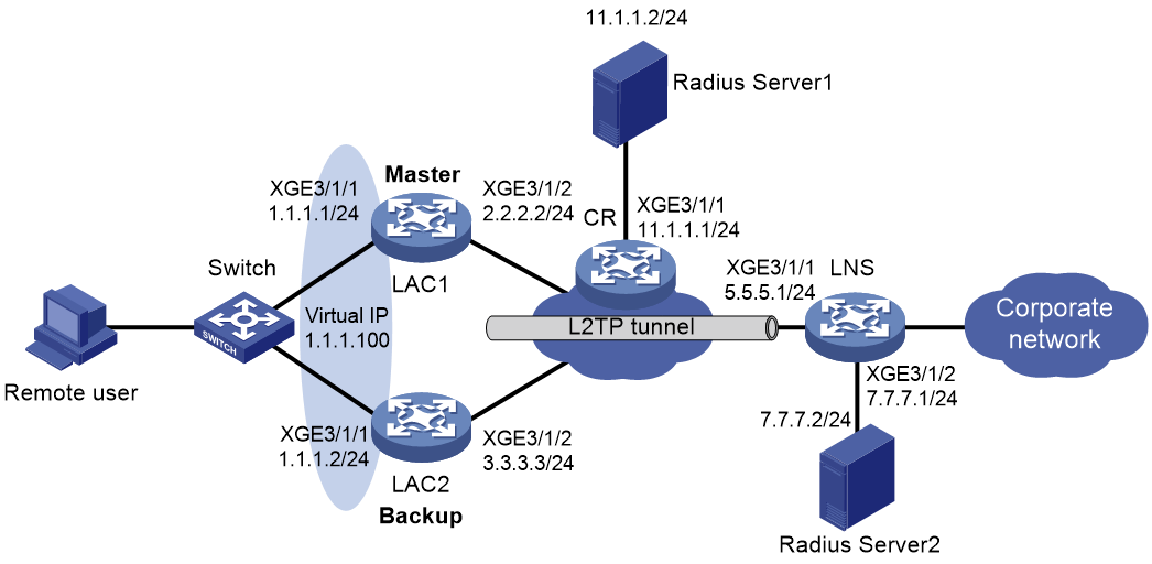
Procedure
1. Assign IP addresses to interfaces, as shown in Figure 9. Configure routes for the remote user, the LACs, the LNS, and the RADIUS servers to reach one another. Make sure the IP address of the interface deployed with VRRP is on the same subnet as the virtual IP address of the VRRP group. (Details not shown.)
2. Configure RADIUS server 1 and RADIUS server 2. (Details not shown.)
3. Configure the LNS:
# Create a RADIUS scheme named rad and enter RADIUS scheme view.
<LNS> system-view
[LNS] radius scheme rad
# Specify the primary authentication server and primary accounting server.
[LNS-radius-rad] primary authentication 7.7.7.2
[LNS-radius-rad] primary accounting 7.7.7.2
# Set the shared key for secure RADIUS authentication and accounting communication.
[LNS-radius-rad] key authentication simple auth2pass
[LNS-radius-rad] key accounting simple auth2pass
# Specify the source IP address as 7.7.7.1 (the IP address of Ten-GigabitEthernet 3/1/2) for outgoing RADIUS packets.
[LNS-radius-rad] nas-ip 7.7.7.1
[LNS-radius-rad] quit
# Enable DHCP and configure an address pool.
[LNS] dhcp enable
[LNS] ip pool pool1
[LNS-ip-pool-pool1] network 192.168.1.0 mask 255.255.255.0 export-route
[LNS-ip-pool-pool1] gateway-list 192.168.1.1 export-route
[LNS-ip-pool-pool1] forbidden-ip 192.168.1.1
[LNS-ip-pool-pool1] quit
# Create ISP domain bbb and configure the domain to use RADIUS scheme rad for authentication, authorization, and accounting for PPP users.
[LNS] domain name bbb
[LNS-isp-bbb] authentication ppp radius-scheme rad
[LNS-isp-bbb] authorization ppp radius-scheme rad
[LNS-isp-bbb] accounting ppp radius-scheme rad
[LNS-isp-bbb] authorization-attribute ip-pool pool1
[LNS-isp-bbb] quit
# Enable L2TP.
[LNS] l2tp enable
# Create interface Virtual-Template 1, and set the PPP authentication mode to PAP.
[LNS] interface virtual-template 1
[LNS-Virtual-Template1] ppp authentication-mode pap domain default enbale bbb
[LNS-Virtual-Template1] quit
# Create L2TP group 1 in LNS mode.
[LNS] l2tp-group 1 mode lns
# Configure the local tunnel name as LNS.
[LNS-l2tp1] tunnel name LNS
# Specify Virtual-Template 1 for receiving calls from the specified LAC.
[LNS-l2tp1] allow l2tp virtual-template 1 remote LAC
# Disable tunnel authentication.
[LNS-l2tp1] undo tunnel authentication
[LNS-l2tp1] quit
4. Configure LAC 1:
# Create a RADIUS scheme named rad and enter RADIUS scheme view.
<LAC1> system-view
[LAC1] radius scheme rad
# Specify the primary authentication server with IP address 11.1.1.2 and UDP port number 1812.
[LAC1-radius-rad] primary authentication 11.1.1.2 1812
# Specify the primary accounting server with IP address 11.1.1.2 and UDP port number 1813.
[LAC1-radius-rad] primary accounting 11.1.1.2 1813
# Set the shared key for secure RADIUS authentication and accounting communication.
[LAC1-radius-rad] key authentication simple auth1pass
[LAC1-radius-rad] key accounting simple auth1pass
# Specify the source IP address as 1.1.1.100 (the virtual IP address of VRRP group 1) for outgoing RADIUS packets.
[LAC1-radius-rad] nas-ip 1.1.1.100
[LAC1-radius-rad] quit
# Create ISP domain bbb and enter ISP domain view.
[LAC1] domain name bbb
# Configure the domain to use RADIUS scheme rad for authentication, authorization, and accounting for PPP users.
[LAC1-isp-bbb] authentication ppp radius-scheme rad
[LAC1-isp-bbb] authorization ppp radius-scheme rad
[LAC1-isp-bbb] accounting ppp radius-scheme rad
[LAC1-isp-bbb] quit
# Create interface Virtual-Template 1 and set the PPP authentication mode to PAP.
[LAC1] interface virtual-template 1
[LAC1-Virtual-Template1] ppp authentication-mode pap domain bbb
[LAC1-Virtual-Template1] quit
# Enable L2TP.
[LAC1] l2tp enable
# Create L2TP group 1 in LAC mode.
[LAC1] l2tp-group 1 mode lac
# Configure the local tunnel name as LAC.
[LAC1-l2tp1] tunnel name LAC
# Specify PPP user user1 as the condition for the LAC to initiate tunneling requests.
[LAC1-l2tp1] user fullusername user1
# Specify the LNS IP address as 5.5.5.1.
[LAC1-l2tp1] lns-ip 5.5.5.1
# Disable tunnel authentication.
[LAC1-l2tp1] undo tunnel authentication
# Associate L2TP group 1 with VSRP instance l2tp1.
[LAC1-l2tp1] vsrp-instance l2tp1
# Specify the source IP address for the L2TP tunnel as 6.6.6.1. After successful VSRP master and backup negotiation, only the master LAC generates a static route to the source address with the loopback interface as the output interface. To forward downstream traffic from LNS to the remote end always through the master LAC, use a dynamic routing protocol to advertise this static route. (Details not shown.)
[LAC1-l2tp1] tunnel vsrp source-ip 6.6.6.1
[LAC1-l2tp1] quit
# Configure the PPPoE server.
[LAC1] interface ten-gigabitethernet 3/1/1
[LAC1-Ten-GigabitEthernet3/1/1] pppoe-server bind virtual-template 1
# Associate the PPPoE server-enabled interface with VSRP instance l2tp1.
[LAC1-Ten-GigabitEthernet3/1/1] bras vsrp-instance l2tp1
[LAC1-Ten-GigabitEthernet3/1/1] quit
# Create track entry 2 to monitor the link status of uplink interface Ten-GigabitEthernet 3/1/2.
[LAC1] track 2 interface ten-gigabitethernet 3/1/2
# Create VRRP group 1 and set its virtual IP address to 1.1.1.100.
[LAC1] interface ten-gigabitethernet 3/1/1.10
[LAC1-Ten-GigabitEthernet3/1/1.10] ip address 1.1.1.1 255.255.255.0
[LAC1-Ten-GigabitEthernet3/1/1.10] vrrp vrid 1 virtual-ip 1.1.1.100
# Set the priority of LAC 1 to 120 in VRRP group 1 on Ten-GigabitEthernet 3/1/1.
[LAC1-Ten-GigabitEthernet3/1/1.10] vrrp vrid 1 priority 120
# Configure LAC 1 to operate in preemptive mode, and set the preemption delay to 90000 centiseconds (15 minutes). When the original master recovers, it has 15 minutes to synchronize data from the new master before switch-back to ensure stability and data consistency of the VRRP group.
[LAC1-Ten-GigabitEthernet3/1/1.10] vrrp vrid 1 preempt-mode delay 90000
# Set the delay time for the IPv6 VRRP group to transition from Initialize to Master or Backup state to 50 seconds.
[LAC1-Ten-GigabitEthernet3/1/1.10] vrrp ipv6 state-transition-delay 50
# Associate VRRP group 1 on Ten-GigabitEthernet 3/1/1 with track entry 2 and decrease the device priority by 50 when the state of track entry 2 changes to Negative.
[LAC1-Ten-GigabitEthernet3/1/1.10] vrrp vrid 1 track 2 priority reduced 50
# Configure Ten-GigabitEthernet 3/1/1.10 to terminate VLAN 10.
[LAC1-Ten-GigabitEthernet3/1/1.10] vlan-type dot1q vid 10
[LAC1-Ten-GigabitEthernet3/1/1.10] quit
# Create VSRP group pname, and enter VSRP peer view.
[LAC1] vsrp peer pname
# Specify the local IP address as 2.2.2.2 and the peer IP address as 3.3.3.3 for VSRP to establish VSRP channels. The default TCP port number for the control channel is used.
[LAC1-vsrp-peer-pname] peer 3.3.3.3 local 2.2.2.2
[LAC1-vsrp-peer-pname] quit
# Create VSRP instance l2tp1 and associate it with VSRP group pname. Set the backup ID of the VSRP instance to 1.
[LAC1] vsrp instance l2tp1
[LAC1-vsrp-instance-l2tp1] backup id 1 peer pname
# Bind VSRP instance l2tp1 to VRRP group 1 on Ten-GigabitEthernet 3/1/1.
[LAC1-vsrp-instance-l2tp1] bind vrrp vrid 1 interface ten-gigabitethernet 3/1/1
[LAC1-vsrp-instance-l2tp1] quit
5. Configure LAC 2:
# Create a RADIUS scheme named rad and enter RADIUS scheme view.
<LAC2> system-view
[LAC2] radius scheme rad
# Specify the primary authentication server with IP address 11.1.1.2 and UDP port number 1812.
[LAC2-radius-rad] primary authentication 11.1.1.2 1812
# Specify the primary accounting server with IP address 11.1.1.2 and UDP port number 1813.
[LAC2-radius-rad] primary accounting 11.1.1.2 1813
# Set the shared key for secure RADIUS authentication and accounting communication.
[LAC2-radius-rad] key authentication simple auth1pass
[LAC2-radius-rad] key accounting simple auth1pass
# Specify the source IP address as 1.1.1.100 (the virtual IP address of VRRP group 1) for outgoing RADIUS packets.
[LAC2-radius-rad] nas-ip 1.1.1.100
[LAC2-radius-rad] quit
# Create ISP domain bbb and enter ISP domain view.
[LAC2] domain name bbb
# Configure the domain to use RADIUS scheme rad for authentication, authorization, and accounting for PPP users.
[LAC2-isp-bbb] authentication ppp radius-scheme rad
[LAC2-isp-bbb] authorization ppp radius-scheme rad
[LAC2-isp-bbb] accounting ppp radius-scheme rad
[LAC2-isp-bbb] quit
# Create interface Virtual-Template 1 and set the PPP authentication mode to PAP.
[LAC2] interface virtual-template 1
[LAC2-Virtual-Template1] ppp authentication-mode pap domain default enable bbb
[LAC2-Virtual-Template1] quit
# Enable L2TP.
[LAC2] l2tp enable
# Create L2TP group 1 in LAC mode.
[LAC2] l2tp-group 1 mode lac
# Configure the local tunnel name as LAC.
[LAC2-l2tp1] tunnel name LAC
# Specify PPP user user1 as the condition for the LAC to initiate tunneling requests.
[LAC2-l2tp1] user fullusername user1
# Specify the LNS IP address as 5.5.5.1.
[LAC2-l2tp1] lns-ip 5.5.5.1
# Disable tunnel authentication.
[LAC2-l2tp1] undo tunnel authentication
# Associate L2TP group 1 with VSRP instance l2tp1.
[LAC2-l2tp1] vsrp-instance l2tp1
# Specify the source IP address for the L2TP tunnel as 6.6.6.1. After successful VSRP master and backup negotiation, only the master LAC generates a static route to the source address with the loopback interface as the output interface. To forward downstream traffic from LNS to the remote end always through the master LAC, use a dynamic routing protocol to advertise this static route. (Details not shown.)
[LAC2-l2tp1] tunnel vsrp source-ip 6.6.6.1
[LAC2-l2tp1] quit
# Configure the PPPoE server.
[LAC2] interface ten-gigabitethernet 3/1/1
[LAC2-Ten-GigabitEthernet3/1/1] pppoe-server bind virtual-template 1
# Associate the PPPoE server with VSRP instance l2tp1.
[LAC2-Ten-GigabitEthernet3/1/1] bras vsrp-instance l2tp1
[LAC2-Ten-GigabitEthernet3/1/1] quit
# Create VRRP group 1 and set its virtual IP address to 1.1.1.100.
[LAC2] interface ten-gigabitethernet 3/1/1.10
[LAC2-Ten-GigabitEthernet3/1/1.10] ip address 1.1.1.2 255.255.255.0
[LAC2-Ten-GigabitEthernet3/1/1.10] vrrp vrid 1 virtual-ip 1.1.1.100
# On Ten-GigabitEthernet 3/1/1.10, associate the direct route with track entry 1 and apply the cost 100 to the direct route when the state of track entry 1 changes to Negative.
[LAC2-Ten-GigabitEthernet3/1/1.10] route-direct track 1 degrade-cost 100
# Configure LAC 2 to operate in preemptive mode without setting the preemption delay. When the priority of the master decreases in the VRRP group, the backup can immediately take over as the new master for service continuity.
[LAC2–Ten-GigabitEthernet3/1/1.10] vrrp vrid 1 preempt-mode
[LAC2-Ten-GigabitEthernet3/1/1.10] quit
# Create VSRP group pname and enter VSRP peer view.
[LAC2] vsrp peer pname
# Specify the local IP address as 3.3.3.3 and the peer address as 2.2.2.2 for VSRP to establish VSRP channels. The default TCP port number for the control channel is used.
[LAC2-vsrp-peer-pname] peer 2.2.2.2 local 3.3.3.3
[LAC2-vsrp-peer-pname] quit
# Create VSRP instance l2tp1 and associate it with VSRP group pname. Set the backup ID of the VSRP instance to 1.
[LAC2] vsrp instance l2tp1
[LAC2-vsrp-instance-l2tp1] backup id 1 peer pname
# Bind VSRP instance l2tp1 to VRRP group 1 on Ten-GigabitEthernet 3/1/1.
[LAC2-vsrp-instance-l2tp1] bind vrrp vrid 1 interface ten-gigabitethernet 3/1/1
[LAC2-vsrp-instance-l2tp1] quit
# To enable RADIUS server 1 to always interact with the master LAC, configure the following settings. After configuration, when both the master and backup LACs redistribute the direct route of subnet 1.1.1.0/24 (where NAS IP address 1.1.1.100 resides) into the dynamic routing protocol (such as OSPF) and advertise the direct route to the upstream CR, the CR learns the subnet route 1.1.1.0/24 advertised by only the master device.
¡ # Create track entry 1 and associate it with VRRP group 1 on interface Ten-GigabitEthernet 3/1/1. When the device is in master state, the associated track entry changes to Positive state. When the device is in backup state, the associated track entry changes to Negative state.
[LAC2] track 1 vrrp interface ten-gigabitethernet 3/1/1.10 vrid 1
[LAC2-track-1] quit
¡ # On Ten-GigabitEthernet 3/1/1, associate the direct route with track entry 1 and apply the cost 100 to the direct route when the state of track entry 1 changes to Negative.
[LAC2] interface ten-gigabitethernet 3/1/1
[LAC2-Ten-GigabitEthernet3/1/1] route-direct track 1 degrade-cost 100
[LAC2-Ten-GigabitEthernet3/1/1] quit
¡ # Redistibute direct routes into OSPF process 100, and specify to use the original cost of redistributed routes. This ensures that the cost value for the routes advertised by the backup device to the CR is larger than the cost value for the routes advertised by the master device. As a result, the CR device learns the subnet route 1.1.1.0/24 advertised by only the master device. (This example uses OSPF to illustrate only the key configuration for route redistribution.)
[LAC2] ospf 100
[LAC2-ospf-100] import-route direct inherit-cost
[LAC2-ospf-100] quit
6. Enter the username user1 and password pwd on the PPPoE client dialup software to initiate a connection request on the remote user.
Verifying the configuration
# Verify that LAC 1 (the master) has synchronized L2TP service data to LAC 2 (the backup).
<LAC1> display vsrp instance l2tp1
VSRP instance name: l2tp1
VSRP peer name: pname
Backup ID: 1
Bound VRID: VRRP VRID 1 interface Ten-GigabitEthernet3/1/1.10
Instance status: Master
Local status: Master
Peer status: Backup
Backup mode: Hot
Traffic backup interval: 10(minutes)
Traffic backup threshold: 50(MB)
Route advertisement: Master only
# Verify that LAC 1 and LAC 2 have the same L2TP sessions.
<LAC1> display ppp sync-session vsrp-instance l2tp1
VSRP instance: l2tp1
VSRP instance state: Master
PSID LTID LSID RSID MAC address IP address
Interface Username IPv6 NDPrefix IPv6 PDPrefix IPv6 address
1 28532 467 32060 6c5d-5cb3-0106 -
XGE3/1/1 user1 - - -
<LAC2> display ppp sync-session vsrp-instance l2tp1
VSRP instance: l2tp1
VSRP instance state: Backup
PSID LTID LSID RSID MAC address IP address
Interface Username IPv6 NDPrefix IPv6 PDPrefix IPv6 address
1 28532 467 32060 6c5d-5cb3-0106 -
XGE3/1/1 user1 - - -
# Verify that LAC 1 and LAC 2 have the same L2TP tunnel information.
<LAC1> display l2tp tunnel vsrp l2tp1
VSRP instance name: l2tp1
VSRP instance state: Master
Total synchronized L2TP tunnels: 1
LocalTID RemoteTID State Sessions RemoteAddress RemotePort RemoteName
28532 4 Established 1 5.5.5.1 1701 LNS
<LAC2> display l2tp tunnel vsrp l2tp1
VSRP instance name: l2tp1
VSRP instance state: Backup
Total synchronized L2TP tunnels: 1
LocalTID RemoteTID State Sessions RemoteAddress RemotePort RemoteName
28532 4 Established 1 5.5.5.1 1701 LNS
# Shut down LAC 1.
# Verify that LAC 2 becomes the master and takes over the L2TP services. LAC 1 becomes the backup. The data channel between them is disconnected.
<LAC2> display vsrp instance l2tp1
VSRP instance name: l2tp1
VSRP peer name: pname
Backup ID: 1
Bound VRID: VRRP VRID 1 interface Ten-GigabitEthernet3/1/1
Instance status: Master
Local status: Master
Peer status: Down
Backup mode: Hot
Traffic backup interval: 10(minutes)
Traffic backup threshold: 50(MB)
Route advertisement: Master only
Example: Configuring VSRP and VRRP collaboration for ARP
Network configuration
As shown in Figure 10, configure VSRP to back up ARP entries between Device A and Device B.
· Enable VSRP for ARP on Ten-GigabitEthernet 3/1/1 of Device A and Device B.
· Configure VRRP on Ten-GigabitEthernet 3/1/1.10 of Device A and Device B, and configure these subinterfaces to terminate VLAN 10.
· Enable OSPF on Device A and Device B to ensure that they can learn and advertise routes on their upstream links.
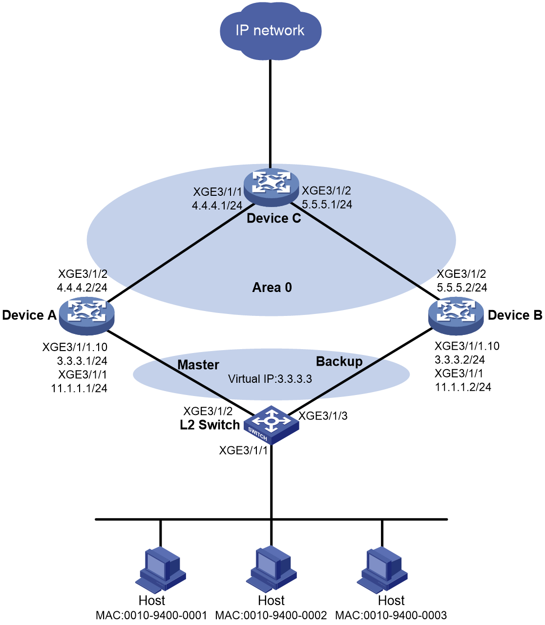
Procedure
1. Assign IP addresses to the interfaces, as shown in Figure 10. (Details not shown.)
2. Configure Device A:
a. Configure a VRRP group:
# Enter Ten-GigabitEthernet 3/1/1.10 interface view.
<DeviceA> system-view
[DeviceA] interface ten-gigabitethernet 3/1/1.10
# Create VRRP group 1 and set its virtual IP address to 3.3.3.3.
[DeviceA–Ten-GigabitEthernet3/1/1.10] vrrp vrid 1 virtual-ip 3.3.3.3
# Configure Ten-GigabitEthernet 3/1/1.10 to terminate VLAN 10.
[DeviceA-Ten-GigabitEthernet3/1/1.10] vlan-type dot1q vid 10
# Set the priority of Device A to 250 in VRRP group 1 on Ten-GigabitEthernet 3/1/1.10. Device A is assigned a higher priority than Device B in VRRP group 1, so Device A can become the master.
[DeviceA-Ten-GigabitEthernet3/1/1.10] vrrp vrid 1 priority 250
# Configure Device A to operate in preemptive mode, and set the preemption delay to 90000 centiseconds (15 minutes). When the original master recovers, it has 15 minutes to synchronize data from the new master before switch-back to ensure stability and data consistency of the VRRP group.
[DeviceA–Ten-GigabitEthernet3/1/1.10] vrrp vrid 1 preempt-mode delay 90000
[DeviceA–Ten-GigabitEthernet3/1/1.10] quit
# Create track entry 1 to monitor the link status of uplink interface Ten-GigabitEthernet 3/1/2. When the uplink fails, the track entry transits to Negative state.
[DeviceA] track 1 interface ten-gigabitethernet 3/1/2
# Associate VRRP group 1 on Ten-GigabitEthernet 3/1/1.10 with track entry 1, and decrease the device priority by 200 when the state of track entry 1 changes to Negative.
[DeviceA] interface ten-gigabitethernet 3/1/1.10
[DeviceA-Ten-GigabitEthernet3/1/1.10] vrrp vrid 1 track 1 priority reduced 200
[DeviceA-Ten-GigabitEthernet3/1/1.10] quit
b. Configure VSRP instance vs1:
# Create VSRP group pr1 and enter VSRP peer view.
[DeviceA] vsrp peer pr1
# Specify the local IP address as 4.4.4.2 and the peer IP address as 5.5.5.2 for VSRP to establish VSRP channels. The default TCP port number for the control channel is used.
[DeviceA-vsrp-peer-pr1] peer 5.5.5.2 local 4.4.4.2
[DeviceA-vsrp-peer-pr1] quit
# Create VSRP instance vs1 and enter its view.
[DeviceA] vsrp instance vs1
# Associate VSRP instance vs1 with VSRP group pr1 and set its backup ID to 1.
[DeviceA-vsrp-instance-vs1] backup id 1 peer pr1
# Bind VSRP instance vs1 to VRRP group 1 on Ten-GigabitEthernet 3/1/1.10.
[DeviceA-vsrp-instance-vs1] bind vrrp vrid 1 interface ten-gigabitethernet 3/1/1.10
c. Configure VSRP for ARP.
# Enter Ten-GigabitEthernet 3/1/1.10 interface view.
[DeviceA] interface ten-gigabitethernet 3/1/1.10
# Associate ARP with VSRP instance vs1.
[DeviceA–Ten-GigabitEthernet3/1/1.10] arp vsrp-instance vs1
[DeviceA–Ten-GigabitEthernet3/1/1.10] quit
# Specify TCP port 1024 for VSRP to establish data channels for ARP service backup.
[DeviceA] arp vsrp-port 1024
d. Configure OSPF:
# Enable OSPF process 1 and set its router ID to 4.4.4.2 (the IP address of Ten-GigabitEthernet 3/1/2).
<DeviceA> system-view
[DeviceA] ospf 1 router-id 4.4.4.2
# Configure OSPF to redistribute the user network route filtered by routing policy 1. Device A then advertises the user network route destined for the subnet where the hosts reside to Device C. In this way, Device C can select the route to a host based on the state of Device A and Device B in the VSRP instance.
[DeviceA-ospf-1] import-route unr inherit-cost route-policy 1
[DeviceA-ospf-1] quit
# Configure routing policy 1 to permit routes destined for network 2.2.2.0/24.
[DeviceA] ip prefix-list 1 permit 2.2.2.0 24
[DeviceA] route-policy 1 permit node 1
[DeviceA-route-policy-1-1] if-match ip address prefix-list 1
[DeviceA-route-policy-1-1] quit
# Configure Area 0.
[DeviceA] ospf
[DeviceA-ospf-1] area 0.0.0.0
[DeviceA-ospf-1-area-0.0.0.0] network 4.4.4.0 0.0.0.255
[DeviceA-ospf-1-area-0.0.0.0] quit
[DeviceA-ospf-1] quit
3. Configure Device B:
a. Configure a VRRP group:
# Enter Ten-GigabitEthernet 3/1/1.10 interface view.
<DeviceB> system-view
[DeviceB] interface ten-gigabitethernet 3/1/1.10
# Create VRRP group 1 and set its virtual IP address to 3.3.3.3.
[DeviceB–Ten-GigabitEthernet3/1/1.10] vrrp vrid 1 virtual-ip 3.3.3.3
# Configure Ten-GigabitEthernet 3/1/1.10 to terminate VLAN 10.
[DeviceB-Ten-GigabitEthernet3/1/1.10] vlan-type dot1q vid 10
# Set the priority of Device B to 200 in VRRP group 1 on Ten-GigabitEthernet 3/1/1.10. Device B is assigned a lower priority than Device A in VRRP group 1, so Device A can become the master.
[DeviceB-Ten-GigabitEthernet3/1/1.10] vrrp vrid 1 priority 200
# Configure Device B to operate in preemptive mode without setting the preemption delay. When the priority of the master decreases in the VRRP group, the backup can immediately take over as the new master for service continuity.
[DeviceB–Ten-GigabitEthernet3/1/1.10] vrrp vrid 1 preempt-mode
[DeviceB–Ten-GigabitEthernet3/1/1.10] quit
b. Configure VSRP instance vs1:
# Create VSRP group pr1 and enter VSRP peer view.
[DeviceB] vsrp peer pr1
# Specify the local IP address as 5.5.5.2 and the peer IP address as 4.4.4.2 for VSRP to establish VSRP channels. The default TCP port number for the control channel is used.
[DeviceB-vsrp-peer-pr1] peer 4.4.4.2 local 5.5.5.2
[DeviceB-vsrp-peer-pr1] quit
# Create VSRP instance vs1 and enter its view.
[DeviceB] vsrp instance vs1
# Associate VSRP instance vs1 with VSRP group pr1 and set its backup ID to 1.
[DeviceB-vsrp-instance-vs1] backup id 1 peer pr1
# Bind VSRP instance vs1 to VRRP group 1 on Ten-GigabitEthernet 3/1/1.10.
[DeviceB-vsrp-instance-vs1] bind vrrp vrid 1 interface ten-gigabitethernet 3/1/1.10
c. Configure VSRP for ARP.
# Enter Ten-GigabitEthernet 3/1/1.10 interface view.
[DeviceB] interface ten-gigabitethernet 3/1/1.10
# Associate ARP with VSRP instance vs1.
[DeviceB–Ten-GigabitEthernet3/1/1.10] arp vsrp-instance vs1
[DeviceB–Ten-GigabitEthernet3/1/1.10] quit
# Specify TCP port 1024 for VSRP to establish data channels for ARP service backup.
[DeviceB] arp vsrp-port 1024
d. Configure OSPF:
# Enable OSPF process 1 and set its router ID to 5.5.5.2 (the IP address of Ten-GigabitEthernet 3/1/2).
[DeviceB] ospf 1 router-id 5.5.5.2
# Configure OSPF to redistribute the user network route filtered by routing policy 1. Device B then advertises the user network route destined for the subnet where the hosts reside to Device C. In this way, Device C can select the route to a host based on the state of Device A and Device B in the VSRP instance.
[DeviceB-ospf-1] import-route unr inherit-cost route-policy 1
[DeviceB-ospf-1] quit
# Configure routing policy 1 to permit routes destined for network 2.2.2.0/24.
[DeviceB] ip prefix-list 1 permit 2.2.2.0 24
[DeviceB] route-policy 1 permit node 1
[DeviceB-route-policy-1-1] if-match ip address prefix-list 1
[DeviceB-route-policy-1-1] quit
# Configure Area 0.
[DeviceB] ospf
[DeviceB-ospf-1] area 0.0.0.0
[DeviceB-ospf-1-area-0.0.0.0] network 5.5.5.0 0.0.0.255
[DeviceB-ospf-1-area-0.0.0.0] quit
[DeviceB-ospf-1] quit
4. Configure Device C:
# Enable OSPF process 1 and set its router ID to 4.4.4.1 (the IP address of Ten-GigabitEthernet 3/1/1).
<DeviceC> system-view
[DeviceC] ospf 1 router-id 4.4.4.1
# Configure OSPF Area 0.
[DeviceC-ospf-1] area 0.0.0.0
[DeviceC-ospf-1-area-0.0.0.0] network 4.4.4.0 0.0.0.255
[DeviceC-ospf-1-area-0.0.0.0] network 5.5.5.0 0.0.0.255
[DeviceC-ospf-1-area-0.0.0.0] quit
[DeviceC-ospf-1] quit
5. Configure the L2 Switch:
a. Create VLAN 10.
<L2Switch> system-view
[L2Switch] vlan 10
[L2Switch-vlan10] quit
b. Configure VLAN settings on the interfaces that connect to Device A and Device B:
# Assign Ten-GigabitEthernet 3/1/2 to VLAN 10.
[L2Switch] interface ten-gigabitethernet 3/1/2
[L2Switch-Ten-GigabitEthernet3/1/2] port link-type trunk
[L2Switch-Ten-GigabitEthernet3/1/2] port trunk permit vlan 10
[L2Switch-Ten-GigabitEthernet3/1/2] quit
# Assign Ten-GigabitEthernet 3/1/3 to VLAN 10.
[L2Switch] interface ten-gigabitethernet 3/1/3
[L2Switch-Ten-GigabitEthernet3/1/3] port link-type trunk
[L2Switch-Ten-GigabitEthernet3/1/3] port trunk permit vlan 10
[L2Switch-Ten-GigabitEthernet3/1/3] quit
Verifying the configuration
# Verify the VSRP configuration on Device A and Device B.
· On the master:
[DeviceA] display vsrp instance
VSRP instance name: vs1
VSRP peer name: pr1
Backup ID:1
Bound VRID: VRRP VRID 1 interface GigabitEthernet0/0/1.10
Instance status: Master
Peer status: Backup
Backup mode: Hot
Traffic backup interval: 10(minutes)
Traffic backup threshold: 50(MB)
Route advertisement: Master only
· On the backup:
[DeviceB] display vsrp instance
VSRP instance name: vs1
VSRP peer name: pr1
Backup ID:1
Bound VRID: VRRP VRID 1 interface GigabitEthernet0/0/1.10
Instance status: Backup
Peer status: Master
Backup mode: Hot
Traffic backup interval: 10(minutes)
Traffic backup threshold: 50(MB)
Route advertisement: Master only
# Verify that Device A and Device B have the same ARP information for Ten-GigabitEthernet 3/1/1.
· On the master:
[DeviceA] display arp all
Type: S-Static D-Dynamic O-Openflow R-Rule M-Multiport I-Invalid
IP address MAC address VLAN/VSI name Interface Aging Type
11.1.1.2 0001-0001-0001 -- XGE3/1/1 20 D
11.1.1.3 0001-0001-0000 -- XGE3/1/1 20 D
11.1.1.4 0001-0000-ffff -- XGE3/1/1 20 D
11.1.1.5 0001-0000-fffe -- XGE3/1/1 20 D
· On the backup:
[DeviceB] display arp all
Type: S-Static D-Dynamic O-Openflow R-Rule M-Multiport I-Invalid
IP address MAC address VLAN/VSI name Interface Aging Type
11.1.1.2 0001-0001-0001 -- XGE3/1/1 -- R
11.1.1.3 0001-0001-0000 -- XGE3/1/1 -- R
11.1.1.4 0001-0000-ffff -- XGE3/1/1 -- R
11.1.1.5 0001-0000-fffe -- XGE3/1/1 -- R
Example: Configuring VSRP and S-Trunk collaboration for ARP
Network configuration
As shown in Figure 11, configure VSRP to back up ARP entries between Device A and Device B.
· Configure smart trunk 1 on Device A and Device B, and assign Route-Aggregation 1 of Device A and Device B to the smart trunk. Configure Route-Aggregation 1 of Device A as the primary member interface, and configure Route-Aggregation 1 of Device B as the secondary member interface.
· Enable VSRP for ARP on Route-Aggregation 1 of Device A and Device B.
· Configure VSRP and S-Trunk collaboration.
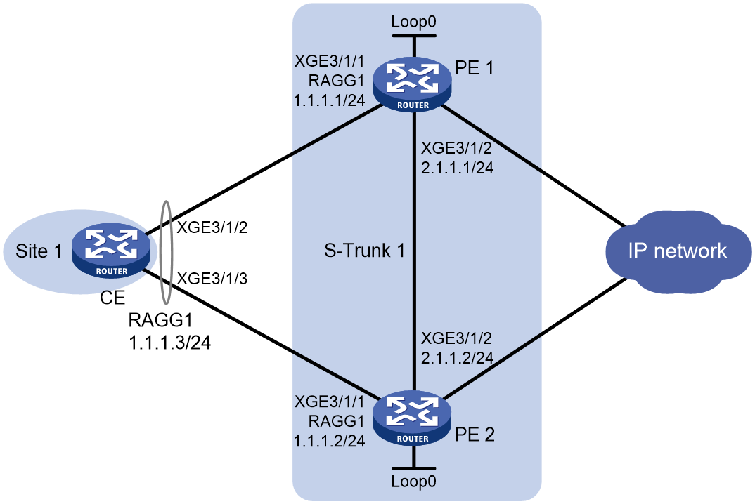
Configuring the CE
1. Assign IP addresses to the interfaces, as shown in Figure 11. (Details not shown.)
2. Configure link aggregation:
<CE> system-view
[CE] interface route-aggregation 1
[CE-Route-Aggregation1] link-aggregation mode dynamic
[CE-Route-Aggregation1] quit
[CE] interface ten-gigabitethernet 3/1/2
[CE-Ten-GigabitEthernet3/1/2] port link-aggregation group 1
[CE-Ten-GigabitEthernet3/1/2] quit
[CE] interface ten-gigabitethernet 3/1/3
[CE-Ten-GigabitEthernet3/1/3] port link-aggregation group 1
[CE-Ten-GigabitEthernet3/1/3] quit
Configuring PE 1
1. Assign IP addresses to the interfaces, as shown in Figure 11. (Details not shown.)
2. Configure LACP system settings to set up the S-Trunk system.
<PE1> system-view
[PE1] lacp system-priority 10
[PE1] lacp system-mac 1-1-1
[PE1] lacp system-number 1
3. Configure S-Trunk protocol packet parameters.
[PE1] s-trunk udp-port 2048
[PE1] s-trunk id 1
[PE1-s-trunk1] s-trunk ip destination 2.1.1.2 source 2.1.1.1
[PE1-s-trunk1] quit
4. Configure static BFD to monitor link status for S-Trunk.
[PE1] bfd static bfd1 peer-ip 2.1.1.2 source-ip 2.1.1.1 discriminator local 1 remote 2
[PE1-bfd-static-session-bfd1] quit
[PE1] s-trunk id 1
[PE1-s-trunk1] s-trunk bfd-session bfd1
[PE1-s-trunk1] quit
5. Create smart trunk 1 and assign member interfaces to it.
[PE1] interface route-aggregation 1
[PE1-Route-Aggregation1] link-aggregation mode dynamic
[PE1-Route-Aggregation1] s-trunk 1
[PE1-Route-Aggregation1] quit
[PE1] interface ten-gigabitethernet 3/1/1
[PE1-Ten-GigabitEthernet3/1/1] port link-aggregation group 1
[PE1-Ten-GigabitEthernet3/1/1] quit
6. Configure a VSRP instance:
# Create VSRP group pr1 and enter VSRP peer view.
[PE1] vsrp peer pr1
# Specify the local IP address 2.1.1.1 and the peer address 2.1.1.2.
[PE1-vsrp-peer-pr1] peer 2.1.1.2 local 2.1.1.1
[PE1-vsrp-peer-pr1] quit
# Create VSRP instance vs1 and enter its view.
[PE1] vsrp instance vs1
# Specify the backup ID of VSRP instance vs1 as 1 in VSRP group pr1.
[PE1-vsrp-instance-vs1] backup id 1 peer pr1
# Bind VSRP instance vs1 to Route-Aggregation 1 in smart trunk 1.
[PE1-vsrp-instance-vs1] bind s-trunk 1 interface route-aggregation 1
[PE1-vsrp-instance-vs1] quit
7. Configure VSRP for ARP:
# Enter the view of Router-Aggregation 1.
[PE1] interface route-aggregation 1
# Associate ARP with VSRP instance vs1.
[PE1–Route-Aggregation1] arp vsrp-instance vs1
[PE1–Route-Aggregation1] quit
# Specify TCP port 1024 for VSRP to establish data channels for ARP service backup.
[PE1] arp vsrp-port 1024
Configuring PE 2
1. Assign IP addresses to the interfaces, as shown in Figure 11. (Details not shown.)
2. Configure LACP system settings to set up the S-Trunk system.
<PE2> system-view
[PE2] lacp system-priority 10
[PE2] lacp system-mac 1-1-1
[PE2] lacp system-number 2
3. Configure S-Trunk protocol packet parameters.
[PE2] s-trunk udp-port 2048
[PE2] s-trunk id 1
[PE2-s-trunk1] s-trunk ip destination 2.1.1.1 source 2.1.1.2
[PE2-s-trunk1] quit
4. Configure static BFD to monitor link status for S-Trunk.
[PE2] bfd static bfd1 peer-ip 2.1.1.1 source-ip 2.1.1.2 discriminator local 2 remote 1
[PE2-bfd-static-session-bfd1] quit
[PE2] s-trunk id 1
[PE2-s-trunk1] s-trunk bfd-session bfd1
[PE2-s-trunk1] quit
5. Create smart trunk 1 and assign member interfaces to it.
[PE2] interface route-aggregation 1
[PE2-Route-Aggregation1] link-aggregation mode dynamic
[PE2-Route-Aggregation1] s-trunk 1
[PE2-Route-Aggregation1] quit
[PE2] interface ten-gigabitethernet 3/1/1
[PE2-Ten-GigabitEthernet3/1/1] port link-aggregation group 1
[PE2-Ten-GigabitEthernet3/1/1] quit
6. Configure a VSRP instance:
# Create VSRP group pr1 and enter VSRP peer view.
[PE2] vsrp peer pr1
# Specify the local IP address 2.1.1.2 and the peer address 2.1.1.1.
[PE2-vsrp-peer-pr1]peer 2.1.1.1 local 2.1.1.2
[PE2-vsrp-peer-pr1] quit
# Create VSRP instance vs1 and enter its view.
[PE2] vsrp instance vs1
# Specify the backup ID of VSRP instance vs1 as 1 in VSRP group pr1.
[PE2-vsrp-instance-vs1] backup id 1 peer pr1
# Bind VSRP instance vs1 to Route-Aggregation 1 in smart trunk 1.
[PE2-vsrp-instance-vs1] bind s-trunk 1 interface route-aggregation 1
[PE2-vsrp-instance-vs1] quit
7. Configure VSRP for ARP:
# Enter the view of Router-Aggregation 1.
[PE2] interface route-aggregation 1
# Associate ARP with VSRP instance vs1.
[PE2–Route-Aggregation1] arp vsrp-instance vs1
[PE2–Route-Aggregation1] quit
# Specify TCP port 1024 for VSRP to establish data channels for ARP service backup.
[PE2] arp vsrp-port 1024
Verifying the configuration
# Verify that the PE 1 and PE 2 are the primary and secondary S-Trunk member devices, respectively.
[PE1] display s-trunk verbose 1
Trunk-wide info and statistics
S-Trunk ID: 1
Revert: Enabled Revert-delay(s): 120
Local bridge MAC: 666d-17c0-0100 Peer bridge MAC: 666d-3a83-0200
Local Priority: 32768 Peer Priority: 32768
DevRole (Trigger): Primary (PRIORITY)
DestIP: 2.1.1.2 SrcIP: 2.1.1.1
Local hello interval(100ms): 10 Local hello timeout(100ms): 200
InStrunkPDUs: 2575 OutStrunkPDUs: 2810
InDrops: 2 OutDrops: 64
Peer hello interval(100ms): 10 Peer hello timeout(100ms): 200
BFD session: bfd1
Trunk member info
Local LinkState ConfigRole OperRole (Trigger) Peer
RAGG1 Up Auto Primary (PEER_MEMBER_DOWN) RAGG1
[PE2] display s-trunk verbose 1
Trunk-wide info and statistics
S-Trunk ID: 1
Revert: Enabled Revert-delay(s): 120
Local bridge MAC: 666d-3a83-0200 Peer bridge MAC: 666d-17c0-0100
Local Priority: 32768 Peer Priority: 32768
DevRole (Trigger): Secondary (PRIORITY)
DestIP: 2.1.1.1 SrcIP: 2.1.1.2
Local hello interval(100ms): 10 Local hello timeout(100ms): 200
InStrunkPDUs: 2634 OutStrunkPDUs: 2664
InDrops: 0 OutDrops: 0
Peer hello interval(100ms): 10 Peer hello timeout(100ms): 200
BFD session: bfd1
Trunk member info
Local LinkState ConfigRole OperRole (Trigger) Peer
RAGG1 Down Auto Secondary (PEER_MEMBER_UP) RAGG1
# Verify that PE 1 and PE 2 are the VSRP master and backup, respectively.
· On the master:
[PE1] display vsrp instance
VSRP instance name: vs1
VSRP peer name: pr1
Backup ID:1
Bound S-Trunk: 1 Interface Route-Aggregation1
Instance status: Master
Local status: Master
Peer status: Backup
Backup mode: Hot
Traffic backup interval: 10(minutes)
Traffic backup threshold: 50(MB)
Route advertisement: Master only
· On the backup:
[PE2] display vsrp instance
VSRP instance name: vs1
VSRP peer name: pr1
Backup ID:1
Bound S-Trunk: 1 Interface Route-Aggregation1
Instance status: Backup
Local status: Backup
Peer status: Master
Backup mode: Hot
Traffic backup interval: 10(minutes)
Traffic backup threshold: 50(MB)
Route advertisement: Master only
# Verify that both Device A and Device B have the ARP information for Route-Aggregation 1.
· On the master:
[PE1] display arp all
Type: S-Static D-Dynamic O-Openflow R-Rule M-Multiport I-Invalid
IP address MAC address VLAN/VSI name Interface Aging Type
1.1.1.3 0001-0001-0001 -- RAGG1 20 D
· On the backup:
[PE2] display arp all
Type: S-Static D-Dynamic O-Openflow R-Rule M-Multiport I-Invalid
IP address MAC address VLAN/VSI name Interface Aging Type
1.1.1.3 0001-0001-0001 -- RAGG1 -- R
Example: Configuring VSRP and VRRP collaboration for ND
Network configuration
As shown in Figure 12, configure VSRP to back up ND entries between Device A and Device B.
· Enable VSRP for ND on Ten-GigabitEthernet 3/1/1 of Device A and Device B.
· Configure VRRP on Ten-GigabitEthernet 3/1/1.10 of Device A and Device B, and configure these subinterfaces to terminate VLAN 10.
· Configure Device A and Device B to set up a VSRP service backup data channel over their upstream links.
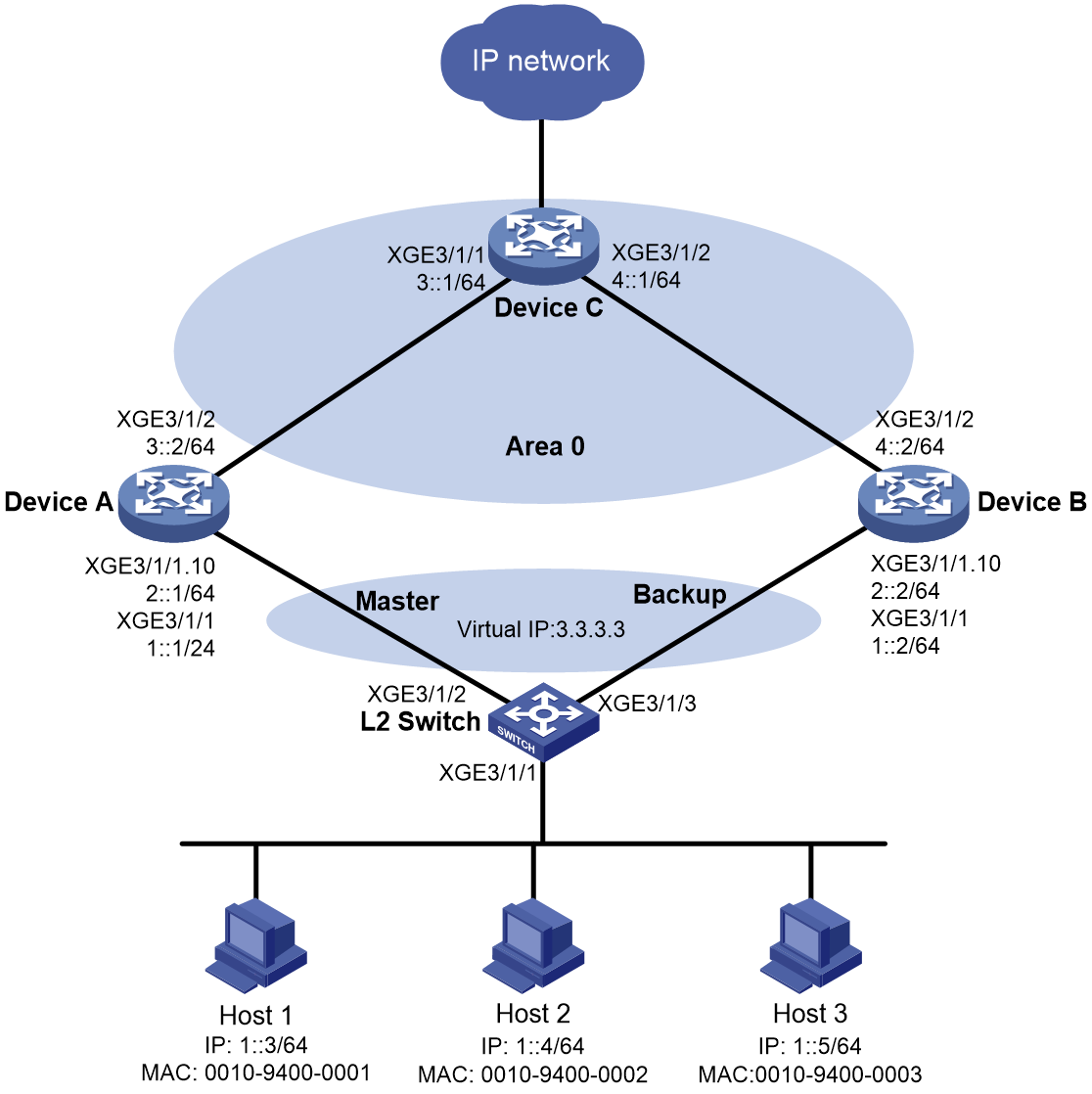
Procedure
1. Assign IPv6 addresses to the interfaces and configure routing, as shown in Figure 12. (Details not shown.)
2. Configure Device A:
a. Configure a VRRP group:
# Enter Ten-GigabitEthernet 3/1/1.10 interface view.
<DeviceA> system-view
[DeviceA] interface ten-gigabitethernet 3/1/1.10
# Create VRRP group 1 and set its virtual IPv6 address to 2::10 and virtual link-local address to FE80::10.
[DeviceA-Ten-GigabitEthernet3/1/1.10]vrrp ipv6 vrid 1 virtual-ip 2::10
[DeviceA-Ten-GigabitEthernet3/1/1.10]vrrp ipv6 vrid 1 virtual-ip FE80::10 link-local
# Configure Ten-GigabitEthernet 3/1/1.10 to terminate VLAN 10.
[DeviceA-Ten-GigabitEthernet3/1/1.10] vlan-type dot1q vid 10
# Set the priority of Device A to 250 in VRRP group 1 on Ten-GigabitEthernet 3/1/1.10. Device A is assigned a higher priority than Device B in VRRP group 1, so Device A can become the master.
[DeviceA-Ten-GigabitEthernet3/1/1.10] vrrp ipv6 vrid 1 priority 250
# Configure Device A to operate in preemptive mode, and set the preemption delay to 90000 centiseconds (15 minutes). When the original master recovers, it has 15 minutes to synchronize data from the new master before switch-back to ensure stability and data consistency of the VRRP group.
[DeviceA–Ten-GigabitEthernet3/1/1.10] vrrp ipv6 vrid 1 preempt-mode delay 90000
[DeviceA–Ten-GigabitEthernet3/1/1.10] quit
# Create track entry 1 to monitor the link status of uplink interface Ten-GigabitEthernet 3/1/2. When the uplink fails, the track entry transits to Negative state.
[DeviceA] track 1 interface ten-gigabitethernet 3/1/2
# Associate VRRP group 1 on Ten-GigabitEthernet 3/1/1.10 with track entry 1, and decrease the device priority by 200 when the state of track entry 1 changes to Negative.
[DeviceA] interface ten-gigabitethernet 3/1/1.10
[DeviceA-Ten-GigabitEthernet3/1/1.10] vrrp ipv6 vrid 1 track 1 priority reduced 200
[DeviceA-Ten-GigabitEthernet3/1/1.10] quit
b. Configure VSRP instance vs1:
# Create VSRP group pr1 and enter VSRP peer view.
[DeviceA] vsrp peer pr1
# Specify the local IP address as 3::2 and the peer IP address as 4::2 for VSRP to establish VSRP channels. The default TCP port number for the control channel is used.
[DeviceA-vsrp-peer-pr1] peer ipv6 4::2 local 3::2
[DeviceA-vsrp-peer-pr1] quit
# Create VSRP instance vs1 and enter its view.
[DeviceA] vsrp instance vs1
# Associate VSRP instance vs1 with VSRP group pr1 and set its backup ID to 1.
[DeviceA-vsrp-instance-vs1] backup id 1 peer pr1
# Bind VSRP instance vs1 to VRRP group 1 on Ten-GigabitEthernet 3/1/1.10.
[DeviceA-vsrp-instance-vs1] bind vrrp ipv6 vrid 1 interface ten-gigabitethernet 3/1/1.10
c. Configure VSRP for ND.
# Enter Ten-GigabitEthernet 3/1/1 interface view.
[DeviceA] interface ten-gigabitethernet 3/1/1
# Associate ND with VSRP instance vs1.
[DeviceA–Ten-GigabitEthernet3/1/1] ipv6 nd vsrp-instance vs1
[DeviceA–Ten-GigabitEthernet3/1/1] quit
# Specify TCP port 1024 for VSRP to establish data channels for ND service backup.
[DeviceA] ipv6 nd vsrp-port 1024
3. Configure Device B:
a. Configure a VRRP group:
# Enter Ten-GigabitEthernet 3/1/1.10 interface view.
<DeviceB> system-view
[DeviceB] interface ten-gigabitethernet 3/1/1.10
# Create VRRP group 1 and set its virtual IPv6 address to 2::10 and virtual link-local address to FE80::10.
[DeviceB-Ten-GigabitEthernet3/1/1.10]vrrp ipv6 vrid 1 virtual-ip 2::10
[DeviceB-Ten-GigabitEthernet3/1/1.10]vrrp ipv6 vrid 1 virtual-ip FE80::10 link-local
# Configure Ten-GigabitEthernet 3/1/1.10 to terminate VLAN 10.
[DeviceB-Ten-GigabitEthernet3/1/1.10] vlan-type dot1q vid 10
# Set the priority of Device B to 200 in VRRP group 1 on Ten-GigabitEthernet 3/1/1.10. Device B is assigned a lower priority than Device A in VRRP group 1, so Device A can become the master.
[DeviceB-Ten-GigabitEthernet3/1/1.10] vrrp ipv6 vrid 1 priority 200
# Configure Device B to operate in preemptive mode without setting the preemption delay. When the priority of the master decreases in the VRRP group, the backup can immediately take over as the new master for service continuity.
[DeviceB–Ten-GigabitEthernet3/1/1.10] vrrp ipv6 vrid 1 preempt-mode
[DeviceB–Ten-GigabitEthernet3/1/1.10] quit
b. Configure VSRP instance vs1:
# Create VSRP group pr1 and enter VSRP peer view.
[DeviceB] vsrp peer pr1
# Specify the local IP address as 4::2 and the peer IP address as 3::2 for VSRP to establish VSRP channels. The default TCP port number for the control channel is used.
[DeviceB-vsrp-peer-pr1] peer ipv6 3::2 local 4::2
[DeviceB-vsrp-peer-pr1] quit
# Create VSRP instance vs1 and enter its view.
[DeviceB] vsrp instance vs1
# Associate VSRP instance vs1 with VSRP group pr1 and set its backup ID to 1.
[DeviceB-vsrp-instance-vs1] backup id 1 peer pr1
# Bind VSRP instance vs1 to VRRP group 1 on Ten-GigabitEthernet 3/1/1.10.
[DeviceB-vsrp-instance-vs1] bind vrrp ipv6 vrid 1 interface ten-gigabitethernet 3/1/1.10
c. Configure VSRP for ND.
# Enter Ten-GigabitEthernet 3/1/1 interface view.
[DeviceB] interface ten-gigabitethernet 3/1/1
# Associate ND with VSRP instance vs1.
[DeviceB–Ten-GigabitEthernet3/1/1] ipv6 nd vsrp-instance vs1
[DeviceB–Ten-GigabitEthernet3/1/1] quit
# Specify TCP port 1024 for VSRP to establish data channels for ND service backup.
[DeviceB] ipv6 nd vsrp-port 1024
4. Configure the L2 Switch:
a. Create VLAN 10.
<L2Switch> system-view
[L2Switch] vlan 10
[L2Switch-vlan10] quit
b. Configure VLAN settings on the interfaces that connect to Device A and Device B:
# Assign Ten-GigabitEthernet 3/1/2 to VLAN 10.
[L2Switch] interface ten-gigabitethernet 3/1/2
[L2Switch-Ten-GigabitEthernet3/1/2] port link-type trunk
[L2Switch-Ten-GigabitEthernet3/1/2] port trunk permit vlan 10
[L2Switch-Ten-GigabitEthernet3/1/2] quit
# Assign Ten-GigabitEthernet 3/1/3 to VLAN 10.
[L2Switch] interface ten-gigabitethernet 3/1/3
[L2Switch-Ten-GigabitEthernet3/1/3] port link-type trunk
[L2Switch-Ten-GigabitEthernet3/1/3] port trunk permit vlan 10
[L2Switch-Ten-GigabitEthernet3/1/3] quit
Verifying the configuration
1. Verify the VSRP configuration on Device A and Device B.
¡ On the master:
[DeviceA] display vsrp instance
VSRP instance name: vs1
VSRP peer name: pr1
Backup ID:1
Bound VRID: VRRP IPv6 VRID 1 interface Ten-GigabitEthernet3/1/1.10
Instance status: Master
Peer status: Backup
Backup mode: Hot
Traffic backup interval: 10(minutes)
Traffic backup threshold: 50(MB)
Route advertisement: Master only
¡ On the backup:
[DeviceB] display vsrp instance
VSRP instance name: vs1
VSRP peer name: pr1
Backup ID:1
Bound VRID: VRRP IPv6 VRID 1 interface Ten-GigabitEthernet3/1/1.10
Instance status: Backup
Peer status: Master
Backup mode: Hot
Traffic backup interval: 10(minutes)
Traffic backup threshold: 50(MB)
Route advertisement: Master only
2. Verify that Device A and Device B have the same ND information for Ten-GigabitEthernet 3/1/1.
¡ On the master:
[DeviceA]dis ipv6 neighbors all
Type: S-Static D-Dynamic O-Openflow R-Rule IS-Invalid static
IPv6 address MAC address VLAN/VSI Interface State T Aging
1::3 0010-9400-0001 -- XGE3/1/1 REACH D 6
¡ On the backup:
[DeviceB]dis ipv6 neighbors all
Type: S-Static D-Dynamic O-Openflow R-Rule IS-Invalid static
IPv6 address MAC address VLAN/VSI Interface State T Aging
1::3 0010-9400-0001 -- XGE3/1/1 REACH R --
Example: Configuring VSRP and S-Trunk collaboration for ND
Network configuration
As shown in Figure 13, configure VSRP to back up ND entries between Device A and Device B.
· Configure smart trunk 1 on Device A and Device B, and assign Route-Aggregation 1 of Device A and Device B to the smart trunk. Configure Route-Aggregation 1 of Device A as the primary member interface, and configure Route-Aggregation 1 of Device B as the secondary member interface.
· Enable VSRP for ND on Route-Aggregation 1 of Device A and Device B.
· Configure VSRP and S-Trunk collaboration.
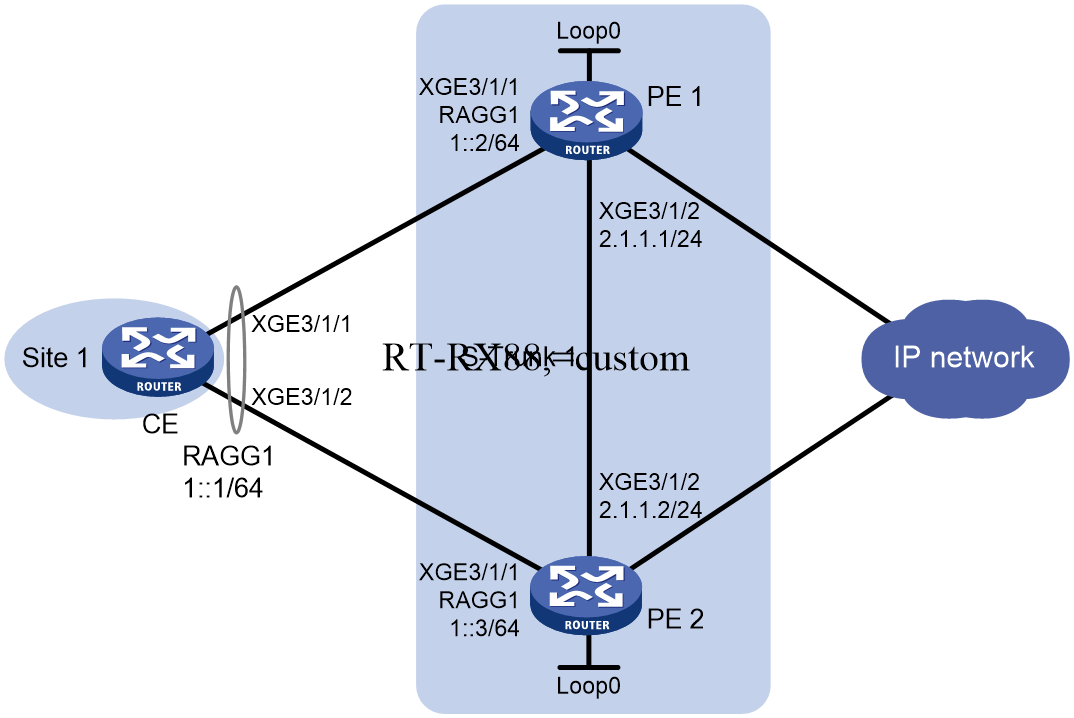
Configuring the CE
1. Assign IP addresses to the interfaces, as shown in Figure 13. (Details not shown.)
2. Configure link aggregation.
<CE> system-view
[CE] interface route-aggregation 1
[CE-Route-Aggregation1] link-aggregation mode dynamic
[CE-Route-Aggregation1] quit
[CE] interface ten-gigabitethernet 3/1/1
[CE-Ten-GigabitEthernet3/1/1] port link-aggregation group 1
[CE-Ten-GigabitEthernet3/1/1] quit
[CE] interface ten-gigabitethernet 3/1/2
[CE-Ten-GigabitEthernet3/1/2] port link-aggregation group 1
[CE-Ten-GigabitEthernet3/1/2] quit
Configuring PE 1
1. Assign IP addresses to the interfaces, as shown in Figure 13. (Details not shown.)
2. Configure LACP system settings to set up the S-Trunk system.
<PE1> system-view
[PE1] lacp system-priority 10
[PE1] lacp system-mac 1-1-1
[PE1] lacp system-number 1
3. Configure S-Trunk protocol packet parameters.
[PE1] s-trunk udp-port 2048
[PE1] s-trunk id 1
[PE1-s-trunk1] s-trunk ip destination 2.1.1.2 source 2.1.1.1
[PE1-s-trunk1] quit
4. Configure static BFD to monitor link status for S-Trunk.
[PE1] bfd static bfd1 peer-ip 2.1.1.2 source-ip 2.1.1.1 discriminator local 1 remote 2
[PE1-bfd-static-session-bfd1] quit
[PE1] s-trunk id 1
[PE1-s-trunk1] s-trunk bfd-session bfd1
[PE1-s-trunk1] quit
5. Create smart trunk 1 and assign member interfaces to it.
[PE1] interface route-aggregation 1
[PE1-Route-Aggregation1] link-aggregation mode dynamic
[PE1-Route-Aggregation1] s-trunk 1
[PE1-Route-Aggregation1] quit
[PE1] interface ten-gigabitethernet 3/1/1
[PE1-Ten-GigabitEthernet3/1/1] port link-aggregation group 1
[PE1-Ten-GigabitEthernet3/1/1] quit
6. Configure a VSRP instance:
# Create VSRP group pr1 and enter VSRP peer view.
[PE1] vsrp peer pr1
# Specify the local IP address 2.1.1.1 and the peer address 2.1.1.2.
[PE1-vsrp-peer-pr1] peer 2.1.1.2 local 2.1.1.1
[PE1-vsrp-peer-pr1] quit
# Create VSRP instance vs1 and enter its view.
[PE1] vsrp instance vs1
# Specify the backup ID of VSRP instance vs1 as 1 in VSRP group pr1.
[PE1-vsrp-instance-vs1] backup id 1 peer pr1
# Bind VSRP instance vs1 to Route-Aggregation 1 in smart trunk 1.
[PE1-vsrp-instance-vs1] bind s-trunk 1 interface route-aggregation 1
[PE1-vsrp-instance-vs1] quit
7. Configure VSRP for ND:
# Enter the view of Router-Aggregation 1.
[PE1] interface route-aggregation 1
# Associate ND with VSRP instance vs1.
[PE1–Route-Aggregation1] ipv6 nd vsrp-instance vs1
[PE1–Route-Aggregation1] quit
Configuring PE 2
1. Assign IP addresses to the interfaces, as shown in Figure 13. (Details not shown.)
2. Configure LACP system settings to set up the S-Trunk system.
<PE2> system-view
[PE2] lacp system-priority 10
[PE2] lacp system-mac 1-1-1
[PE2] lacp system-number 2
3. Configure S-Trunk protocol packet parameters.
[PE2] s-trunk udp-port 2048
[PE2] s-trunk id 1
[PE2-s-trunk1] s-trunk ip destination 2.1.1.1 source 2.1.1.2
[PE2-s-trunk1] quit
4. Configure static BFD to monitor link status for S-Trunk.
[PE2] bfd static bfd1 peer-ip 2.1.1.1 source-ip 2.1.1.2 discriminator local 2 remote 1
[PE2] s-trunk id 1
[PE2-s-trunk1] s-trunk bfd-session bfd1
[PE2-s-trunk1] quit
5. Create smart trunk 1 and assign member interfaces to it.
[PE2] interface route-aggregation 1
[PE2-Route-Aggregation1] link-aggregation mode dynamic
[PE2-Route-Aggregation1] s-trunk 1
[PE2-Route-Aggregation1] quit
[PE2] interface ten-gigabitethernet 3/1/1
[PE2-Ten-GigabitEthernet3/1/1] port link-aggregation group 1
[PE2-Ten-GigabitEthernet3/1/1] quit
6. Configure a VSRP instance:
# Create VSRP group pr1 and enter VSRP peer view.
[PE2] vsrp peer pr1
# Specify the local IP address 2.1.1.2 and the peer address 2.1.1.1.
[PE2-vsrp-peer-pr1] peer 2.1.1.1 local 2.1.1.2
[PE2-vsrp-peer-pr1] quit
# Create VSRP instance vs1 and enter its view.
[PE2] vsrp instance vs1
# Specify the backup ID of VSRP instance vs1 as 1 in VSRP group pr1.
[PE2-vsrp-instance-vs1] backup id 1 peer pr1
# Bind VSRP instance vs1 to Route-Aggregation 1 in smart trunk 1.
[PE2-vsrp-instance-vs1] bind s-trunk 1 interface route-aggregation 1
[PE2-vsrp-instance-vs1] quit
7. Configure VSRP for ND:
# Enter the view of Router-Aggregation 1.
[PE2] interface route-aggregation 1
# Associate ND with VSRP instance vs1.
[PE2–Route-Aggregation1] ipv6 nd vsrp-instance vs1
[PE2–Route-Aggregation1] quit
Verifying the configuration
1. Verify that PE 1 and PE 2 are the primary and secondary S-Trunk member devices, respectively.
# Verify that PE 1 is the primary S-Trunk member device.
[PE1] display s-trunk verbose 1
Trunk-wide info and statistics
S-Trunk ID: 1
Revert: Enabled Revert-delay(s): 120
Local bridge MAC: 46e4-b684-0200 Peer bridge MAC: 46e4-bba4-0300
Local priority: 32768 Peer priority: 32768
DevRole (Trigger): Primary (PRIORITY)
DestIP: 2.1.1.2 SrcIP: 2.1.1.1
Local hello interval(100ms): 10 Local hello timeout(100ms): 200
InStrunkPDUs: 1222 OutStrunkPDUs: 1408
InDrops: 1 OutDrops: 0
Peer hello interval(100ms): 10 Peer hello timeout(100ms): 200
Sequence number check: Disabled
BFD session: -
VPN instance: -
Description: -
Trunk member info
Local LinkState ConfigRole OperRole (Trigger) Peer
RAGG1 Up Auto Primary (PEER_MEMBER_DOWN) RAGG1
# Verify that PE 2 is the secondary S-Trunk member device.
[PE2] display s-trunk verbose 1
Trunk-wide info and statistics
S-Trunk ID: 1
Revert: Enabled Revert-delay(s): 120
Local bridge MAC: 46e4-bba4-0300 Peer bridge MAC: 46e4-b684-0200
Local priority: 32768 Peer priority: 32768
DevRole (Trigger): Secondary (PRIORITY)
DestIP: 2.1.1.1 SrcIP: 2.1.1.2
Local hello interval(100ms): 10 Local hello timeout(100ms): 200
InStrunkPDUs: 1299 OutStrunkPDUs: 1258
InDrops: 0 OutDrops: 0
Peer hello interval(100ms): 10 Peer hello timeout(100ms): 200
Sequence number check: Disabled
BFD session: -
VPN instance: -
Description: -
Trunk member info
Local LinkState ConfigRole OperRole (Trigger) Peer
RAGG1 Down Auto Secondary (PEER_MEMBER_UP) RAGG1
2. Verify that PE 1 and PE 2 are the VSRP master and backup, respectively.
¡ On the master:
[PE1] display vsrp instance
VSRP instance name: vs1
VSRP peer name: pr1
Backup ID: 1
Bound S-Trunk ID: 1 Interface Route-Aggregation1
Instance status: Master
Local status: Master
Peer status: Backup
Backup mode: Hot
Traffic backup interval: 10(minutes)
Traffic backup threshold: 50(MB)
Route advertisement: Master only
¡ On the backup:
[PE2] display vsrp instance
VSRP instance name: vs1
VSRP peer name: pr1
Backup ID: 1
Bound S-Trunk ID: 1 Interface Route-Aggregation1
Instance status: Backup
Local status: Backup
Peer status: Master
Backup mode: Hot
Traffic backup interval: 10(minutes)
Traffic backup threshold: 50(MB)
Route advertisement: Master only
3. Verify that both Device A and Device B have the ND information for Route-Aggregation 1.
¡ On the master:
[PE1] display ipv6 neighbors all
Type: S-Static D-Dynamic O-Openflow R-Rule IS-Invalid static
IPv6 address MAC address VLAN/VSI Interface State T Aging
1::1 46e4-afbf-0102 -- RAGG1 REACH D 23
FE80::44E4:AFFF:FEBF:102 46e4-afbf-0102 -- RAGG1 REACH D 13
¡ On the backup:
[PE2] display ipv6 neighbors all
Type: S-Static D-Dynamic O-Openflow R-Rule IS-Invalid static
IPv6 address MAC address VLAN/VSI Interface State T Aging
1::1 46e4-afbf-0102 -- RAGG1 REACH R --
FE80::44E4:AFFF:FEBF:102 46e4-afbf-0102 -- RAGG1 REACH R --
Example: Configuring VSRP for IGMP
Network configuration
As shown in Figure 14, configure VSRP to back up IGMP multicast information for IPv4 IPoE users on Ten-GigabitEthernet 3/1/1.10.
Perform the following tasks:
· Configure IPoE, VSRP instance, and VRRP settings as described in "Example: Configuring VSRP for IPoE (IPv4 address pool)."
· Enable IGMP and per-session multicast forwarding on Ten-GigabitEthernet 3/1/1.10 on both Device A and Device B.
· Enable PIM-SM on Device A, Device B, and Device C.
· Configure Device C as the RP.
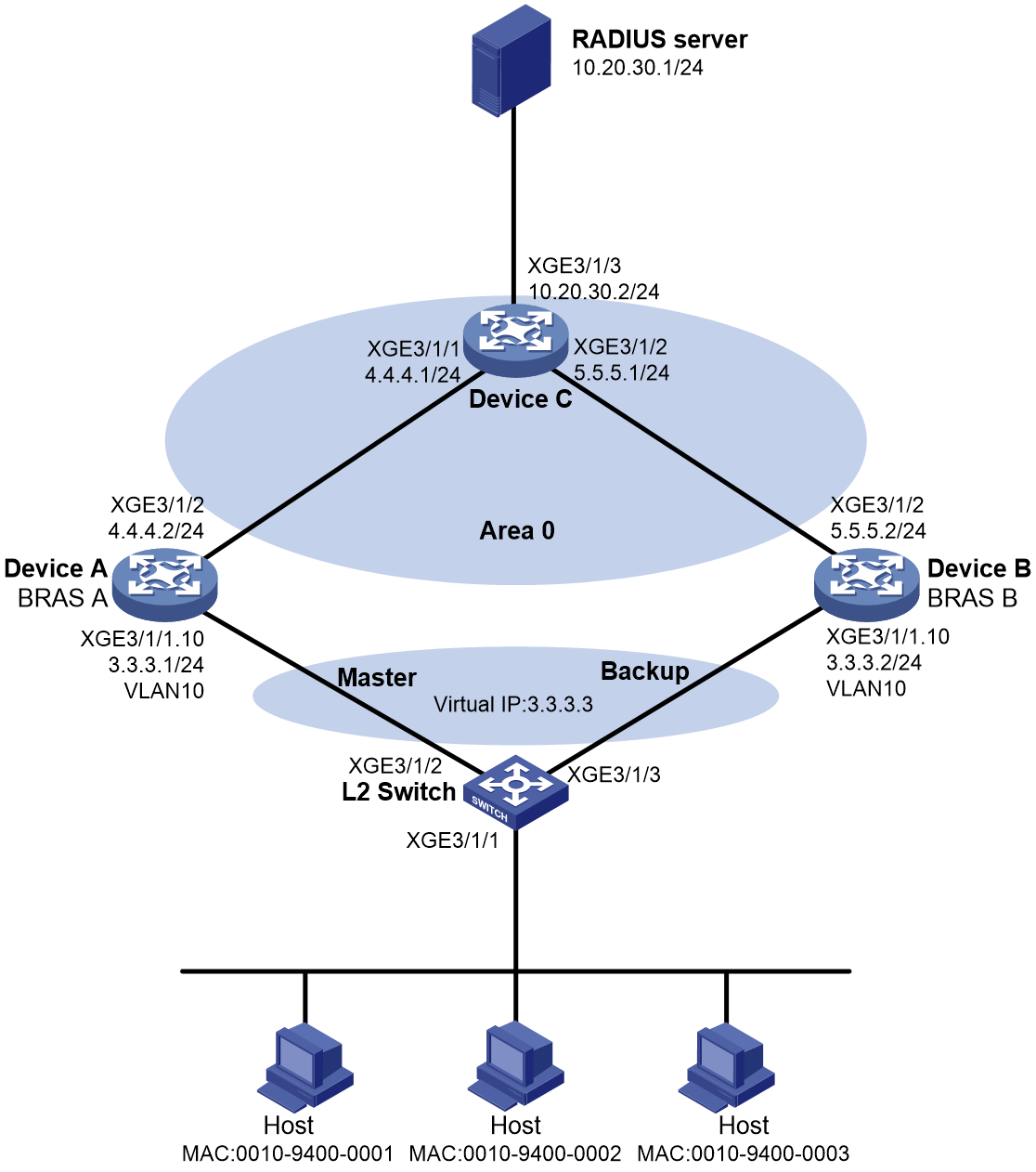
Procedure
1. Assign IP addresses to interfaces, as shown in Figure 14. Configure routes for the hosts, the BRASs, the RP, and the RADIUS server to reach one another. (Details not shown.)
2. Configure the RADIUS servers as described in "Example: Configuring VSRP for IPoE (IPv4 address pool)."
3. Configure Device A:
# Configure IPoE, VRRP group, and VSRP instance settings as described in "Example: Configuring VSRP for IPoE (IPv4 address pool)." In this example, the VSRP instance name is vsrp1.
# Enable IP multicast routing.
<DeviceA> system-view
[DeviceA] multicast routing
[DeviceA-mrib] quit
# Enable IGMP and per-session multicast forwarding on Ten-GigabitEthernet 3/1/1.10 (the downstream interface). Enable PIM-SM on Ten-GigabitEthernet 3/1/2 (the upstream interface).
[DeviceA] interface ten-gigabitethernet 3/1/1.10
[DeviceA-Ten-GigabitEthernet3/1/1.10] igmp enable
[DeviceA-Ten-GigabitEthernet3/1/1.10] igmp join-by-session
[DeviceA-Ten-GigabitEthernet3/1/1.10] quit
[DeviceA] interface ten-gigabitethernet 3/1/2
[DeviceA-Ten-GigabitEthernet3/1/2] pim sm
[DeviceA-Ten-GigabitEthernet3/1/2] quit
# Associate VSRP instance vsrp1 with Ten-GigabitEthernet 3/1/1.10 for IGMP service backup.
[DeviceA] interface ten-gigabitethernet 3/1/1.10
[DeviceA-Ten-GigabitEthernet3/1/1.10] igmp vsrp-instance vsrp1
[DeviceA-Ten-GigabitEthernet3/1/1.10] quit
4. Configure Device B:
# Configure IPoE, VRRP group, and VSRP instance settings as described in "Example: Configuring VSRP for IPoE (IPv4 address pool)." In this example, the VSRP instance name is vsrp1.
# Enable IP multicast routing.
<DeviceB> system-view
[DeviceB] multicast routing
[DeviceB-mrib] quit
# Enable IGMP and per-session multicast forwarding on Ten-GigabitEthernet 3/1/1.10 (the downstream interface). Enable PIM-SM on Ten-GigabitEthernet 3/1/2 (the upstream interface).
[DeviceB] interface ten-gigabitethernet 3/1/1.10
[DeviceB-Ten-GigabitEthernet3/1/1.10] igmp enable
[DeviceB-Ten-GigabitEthernet3/1/1.10] igmp join-by-session
[DeviceB-Ten-GigabitEthernet3/1/1.10] quit
[DeviceB] interface ten-gigabitethernet 3/1/2
[DeviceB-Ten-GigabitEthernet3/1/2] pim sm
[DeviceB-Ten-GigabitEthernet3/1/2] quit
# Associate VSRP instance vsrp1 with Ten-GigabitEthernet 3/1/1.10 for IGMP service backup.
[DeviceB] interface ten-gigabitethernet 3/1/1.10
[DeviceB-Ten-GigabitEthernet3/1/1.10] igmp vsrp-instance vsrp1
[DeviceB-Ten-GigabitEthernet3/1/1.10] quit
5. Configure Device C:
# Enable IP multicast routing.
<DeviceC> system-view
[DeviceC] multicast routing
[DeviceC-mrib] quit
# Enable PIM-SM on Ten-GigabitEthernet 3/1/1, Ten-GigabitEthernet 3/1/2, and Ten-GigabitEthernet 3/1/3.
[DeviceC] interface ten-gigabitethernet 3/1/1
[DeviceC-Ten-GigabitEthernet3/1/1] pim sm
[DeviceC-Ten-GigabitEthernet3/1/1] quit
[DeviceC] interface ten-gigabitethernet 3/1/2
[DeviceC-Ten-GigabitEthernet3/1/2] pim sm
[DeviceC-Ten-GigabitEthernet3/1/2] quit
[DeviceC] interface ten-gigabitethernet 3/1/3
[DeviceC-Ten-GigabitEthernet3/1/3] pim sm
[DeviceC-Ten-GigabitEthernet3/1/3] quit
# Configure Device C as the BSR and the RP.
[DeviceC] pim
[DeviceC-pim] c-bsr 10.20.30.2
[DeviceC-pim] c-rp 10.20.30.2
[DeviceC-pim] quit
Verifying the configuration
# Verify that Device A (the master) and Device B (the backup) have the same IGMP interface and group information about IPoE users.
· On the master:
[DeviceA] display igmp interface verbose
Multicast-UA0(3.3.3.1):
IGMP is enabled.
IGMP version: 2
Query interval for IGMP: 125s
Other querier present time for IGMP: 255s
Maximum query response time for IGMP: 10s
Last member query interval: 1s
Last member query count: 2
Startup query interval: 31s
Startup query count: 2
General query timer expiry (hh:mm:ss): 00:01:48
Querier for IGMP: 3.3.3.1 (This router)
IGMP activity: 1 join(s), 0 leave(s)
Multicast routing on this interface: Enabled
Robustness: 2
Require-router-alert: Disabled
Fast-leave: Disabled
Startup-query: Off
Other-querier-present-timer-expiry (hh:mm:ss): Off
Authorization: Disabled
Join-by-session: Enabled
User-VLAN-aggregation: Disabled
Access interface: Ten-GigabitEthernet3/1/1.10
VSRP instance: vsrp1 (State is master, synchronization is on)
IGMP groups reported in total: 1
[DeviceA] display igmp group
IGMP groups in total: 1
Multicast-UA0(3.3.3.1):
IGMP groups reported in total: 1
Group address Last reporter Uptime Expires
225.1.1.1 3.3.3.7 00:04:18 00:04:19
· On the backup:
[DeviceB] display igmp interface verbose
Multicast-UA1(3.3.3.2):
IGMP is enabled.
IGMP version: 2
Query interval for IGMP: 125s
Other querier present time for IGMP: 255s
Maximum query response time for IGMP: 10s
Last member query interval: 1s
Last member query count: 2
Startup query interval: 31s
Startup query count: 2
General query timer expiry (hh:mm:ss): off
Querier for IGMP: 3.3.3.2 (This router)
IGMP activity: 1 join(s), 0 leave(s)
Multicast routing on this interface: Enabled
Robustness: 2
Require-router-alert: Disabled
Fast-leave: Disabled
Startup-query: Off
Other-querier-present-timer-expiry (hh:mm:ss): Off
Authorization: Disabled
Join-by-session: Enabled
User-VLAN-aggregation: Disabled
Access interface: Ten-GigabitEthernet3/1/1.10
VSRP instance: vsrp1 (State is backup)
IGMP groups reported in total: 1
[DeviceB] display igmp group
IGMP groups in total: 1
Multicast-UA1(3.3.3.2):
IGMP groups reported in total: 1
Group address Last reporter Uptime Expires
225.1.1.1 3.3.3.7 00:04:18 00:04:19
Example: Configuring VSRP load sharing on an IGMP-enabled interface
Network configuration
As shown in Figure 15, perform the following tasks:
· Enable IGMP on the interface of the access device (Device D) connected to the user.
· Configure PIM and enable PIM-SM on the interfaces connecting the access devices and upstream router (Device C).
· Configure the upstream router as the RP.
· Add the downstream interfaces on Device A and Device B to the same Layer 3 aggregation group.
· Connect Device D to Device A and Device B through a Layer 2 aggregate interface.
· Configure the source and destination IP addresses for the S-Trunk protocol packets (without OSPF configuration).

Procedure
1. Assign IP addresses to the interfaces, and configure routes for the devices to reach one another. (Details not shown.)
2. Configure Device A:
# Set the destination UDP port of IPv4 S-Trunk protocol packets.
<DeviceA> system-view
[DeviceA] s-trunk udp-port 2048
# Associate track entry 1 with static BFD session bfd2.
[DeviceA] track 1 bfd static bfd2
# Create a monitor link group and specify member interfaces for it.
[DeviceA] monitor-link group 1
[DeviceA-mtlk-group1] port ten-gigabitethernet 3/1/1 downlink
[DeviceA-mtlk-group1] port ten-gigabitethernet 3/1/2 uplink
[DeviceA-mtlk-group1] quit
# Create a Layer 3 aggregate interface operating in dynamic link aggregation mode, and enable PIM and IGMP on the interface.
[DeviceA] interface Route-Aggregation1
[DeviceA-Route-Aggregation1] link-aggregation mode dynamic
[DeviceA-Route-Aggregation1] pim sm
[DeviceA-Route-Aggregation1] igmp enable
[DeviceA-Route-Aggregation1] quit
# Specify the local IP address as 1.1.1.1 and the peer IP address as 1.1.1.2 for VSRP to establish VSRP channels, and associate a track entry with VSRP.
[DeviceA] vsrp peer 1
[DeviceA-vsrp-peer-1] peer 1.1.1.2 local 1.1.1.1
[DeviceA-vsrp-peer-1] track 1
[DeviceA-vsrp-peer-1] quit
# Create a VSRP instance.
[DeviceA] vsrp instance 1
[DeviceA-vsrp-instance-1] backup id 1 peer 1
[DeviceA-vsrp-instance-1] bind s-trunk 1 interface Route-Aggregation1
[DeviceA-s-trunk1]quit
# Configure S-Trunk parameters.
[DeviceA] s-trunk id 1
[DeviceA-s-trunk1] s-trunk bfd-session strunk1
[DeviceA-s-trunk1] s-trunk role priority 100
[DeviceA-s-trunk1] s-trunk ip destination 23.0.0.12 source 23.0.0.21
[DeviceA-s-trunk1] quit
# Associate IGMP-enabled interface Route-Aggregation 1 with a VSRP instance, configure the role of the S-Trunk member interface as primary, and enable VSRP load sharing on the interface
[DeviceA] interface Route-Aggregation1
[DeviceA-Route-Aggregation1] igmp vsrp-instance 1
[DeviceA-Route-Aggregation1] igmp vsrp-load-balance restore-delay 30
[DeviceA-Route-Aggregation1] s-trunk 1
[DeviceA-Route-Aggregation1] s-trunk port-role primary
[DeviceA-Route-Aggregation1] quit
# Create a loopback interface to establish VSRP channels.
[DeviceA] interface LoopBack1
[DeviceA-LoopBack1] ip address 1.1.1.1 255.255.255.255
[DeviceA-LoopBack1] ospf 1 area 0.0.0.0
[DeviceA-LoopBack1] pim sm
[DeviceA-LoopBack1] quit
# Configure static BFD to monitor link status for S-Trunk.
[DeviceA] bfd static bfd2 peer-ip 1.1.1.2 source-ip 1.1.1.1 discriminator local 3 remote 4
[DeviceA-bfd-static-session-bfd2] quit
[DeviceA] bfd static strunk1 peer-ip 23.0.0.12 source-ip 23.0.0.21 discriminator local 1 remote 2
[DeviceA-bfd-static-session-strunk1] quit
# Enable IP multicast routing.
[DeviceA] multicast routing
3. Configure Device B:
Configure Device B in the same way Device A is configured. (Details not shown.)
4. Configure Device C:
# Enable IP multicast routing.
<DeviceC> system-view
[DeviceC] multicast routing
[DeviceC-mrib] quit
# Enable PIM-SM on both the upstream and downstream interfaces.
[DeviceC] interface ten-gigabitethernet 3/1/1
[DeviceC-Ten-GigabitEthernet3/1/1] pim sm
[DeviceC-Ten-GigabitEthernet3/1/1] quit
[DeviceC] interface ten-gigabitethernet 3/1/2
[DeviceC-Ten-GigabitEthernet3/1/2] pim sm
[DeviceC-Ten-GigabitEthernet3/1/2] quit
[DeviceC] interface ten-gigabitethernet 3/1/3
[DeviceC-Ten-GigabitEthernet3/1/3] pim sm
[DeviceC-Ten-GigabitEthernet3/1/3] quit
# Configure Device C as the BSR and RP.
[DeviceC] pim
[DeviceC-pim] c-bsr 10.0.0.12
[DeviceC-pim] c-rp 10.0.0.12
[DeviceC-pim] quit
Verifying the configuration
# Verify that Device A (the master) and Device B (the backup) have the same IGMP interface and group information. The master and backup devices forward multicast traffic for odd multicast group addresses and even multicast group addresses, respectively.
· On the master:
[DeviceA] display igmp interface verbose
Route-Aggregation1(31.0.0.2):
IGMP is enabled.
IGMP version: 2
Query interval for IGMP: 125s
Other querier present time for IGMP: 255s
Maximum query response time for IGMP: 10s
Last member query interval: 1s
Last member query count: 2
Startup query interval: 31s
Startup query count: 2
General query timer expiry (hh:mm:ss): 00:01:00
Querier for IGMP: 31.0.0.2 (This router)
IGMP activity: 5935 join(s), 1934 leave(s)
Multicast routing on this interface: Enabled
Robustness: 2
Require-router-alert: Disabled
Fast-leave: Disabled
Startup-query: Off
Other-querier-present-timer-expiry (hh:mm:ss): Off
Authorization: Disabled
Join-by-session: Disabled
User-VLAN-aggregation: Disabled
VSRP instance: 1 (State is master, synchronization is on)
VSRP forward mode: odd (Wait to restore is 30s)
IGMP groups reported in total: 4001
· On the backup:
[DeviceB] display igmp interface verbose
Route-Aggregation1(31.0.0.1):
IGMP is enabled.
IGMP version: 2
Query interval for IGMP: 125s
Other querier present time for IGMP: 255s
Maximum query response time for IGMP: 10s
Last member query interval: 1s
Last member query count: 2
Startup query interval: 31s
Startup query count: 2
General query timer expiry (hh:mm:ss): Off
Querier for IGMP: 31.0.0.1 (This router)
IGMP activity: 6068 join(s), 2067 leave(s)
Multicast routing on this interface: Enabled
Robustness: 2
Require-router-alert: Disabled
Fast-leave: Disabled
Startup-query: On
Other-querier-present-timer-expiry (hh:mm:ss): Off
Authorization: Disabled
Join-by-session: Disabled
User-VLAN-aggregation: Disabled
VSRP instance: 1 (State is backup)
VSRP forward mode: even (Wait to restore is 30s)
IGMP groups reported in total: 4001
Example: Configuring VSRP for MLD
Network configuration
As shown in Figure 16, configure VSRP to back up MLD multicast information for IPv6 IPoE users on Ten-GigabitEthernet 3/1/1.10.
Perform the following tasks:
· Configure IPoE, VSRP instance, and VRRP settings as described in "Example: Configuring VSRP for IPoE (IPv6 address pool)."
· Enable MLD and per-session multicast forwarding on Ten-GigabitEthernet 3/1/1.10 on both Device A and Device B.
· Enable IPv6 PIM-SM on Device A, Device B, and Device C.
· Configure Device C as the RP.
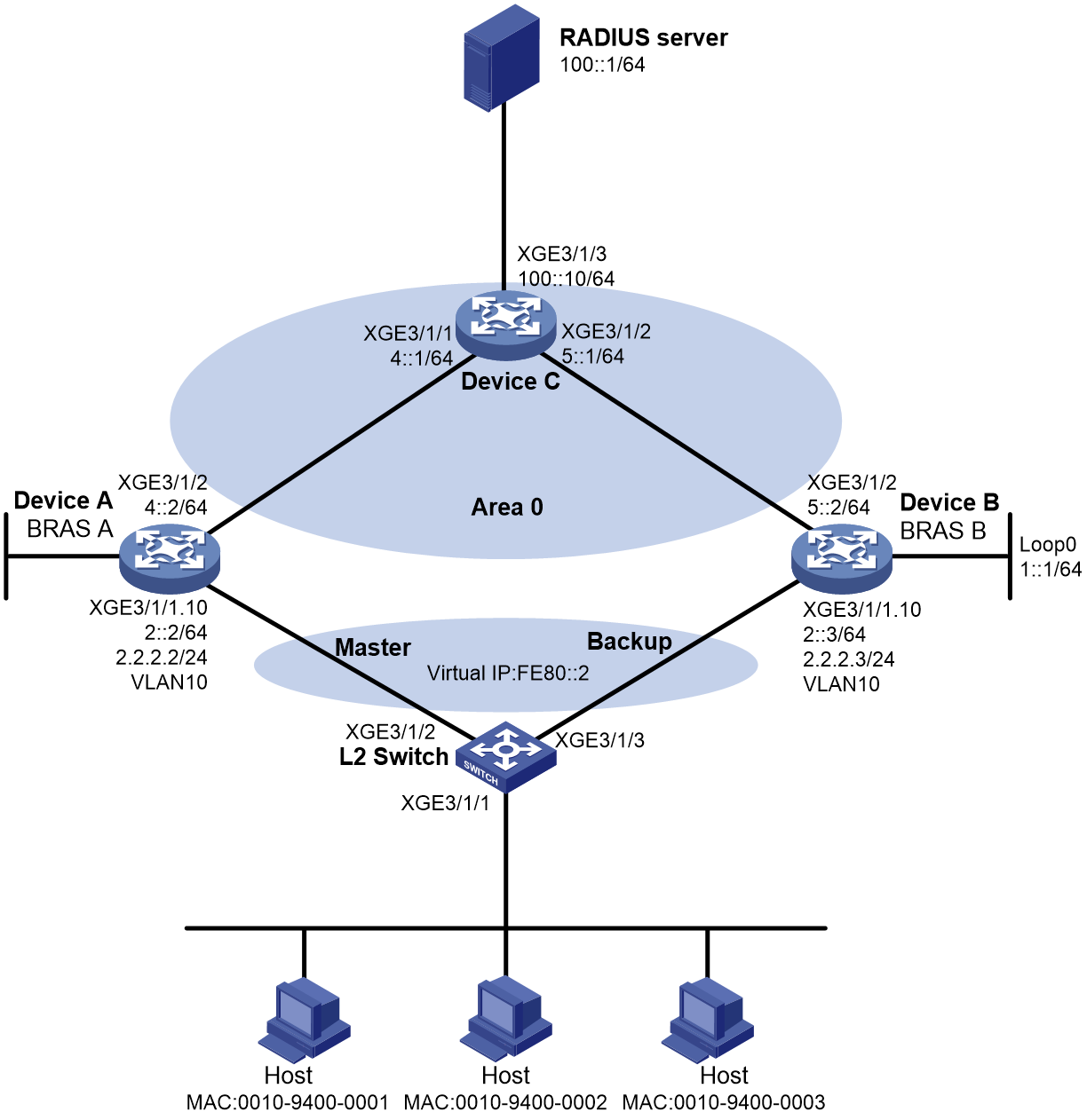
Procedure
1. Assign IPv6 addresses to interfaces, as shown in Figure 16. Configure routes for the hosts, the BRASs, the RP, and the RADIUS server to reach one another. (Details not shown.)
2. Configure the RADIUS servers as described in "Example: Configuring VSRP for IPoE (IPv6 address pool)."
3. Configure Device A:
# Configure IPoE, VRRP group, and VSRP instance settings as described in "Example: Configuring VSRP for IPoE (IPv6 address pool)." In this example, the VSRP instance name is vsrp1.
# Enable IPv6 multicast routing.
<DeviceA> system-view
[DeviceA] ipv6 multicast routing
[DeviceA-mrib6] quit
# Enable MLD and per-session multicast forwarding on Ten-GigabitEthernet 3/1/1.10. Enable IPv6 PIM-SM on Ten-GigabitEthernet 3/1/2.
[DeviceA] interface ten-gigabitethernet 3/1/1.10
[DeviceA-Ten-GigabitEthernet3/1/1.10] mld enable
[DeviceA-Ten-GigabitEthernet3/1/1.10] mld join-by-session
[DeviceA-Ten-GigabitEthernet3/1/1.10] quit
[DeviceA] interface ten-gigabitethernet 3/1/2
[DeviceA-Ten-GigabitEthernet3/1/2] ipv6 pim sm
[DeviceA-Ten-GigabitEthernet3/1/2] quit
# Associate VSRP instance vsrp1 with Ten-GigabitEthernet 3/1/1.10 for MLD multicast service backup.
[DeviceA] interface ten-gigabitethernet 3/1/1.10
[DeviceA-Ten-GigabitEthernet3/1/1.10] mld vsrp-instance vsrp1
[DeviceA-Ten-GigabitEthernet3/1/1.10] quit
4. Configure Device B:
# Configure IPv6 IPoE, VRRP group, and VSRP instance settings as described in "Example: Configuring VSRP for IPoE (IPv6 address pool)." In this example, the VSRP instance name is vsrp1.
# Enable IPv6 multicast routing.
<DeviceB> system-view
[DeviceB] ipv6 multicast routing
[DeviceB-mrib6] quit
# Enable MLD and per-session multicast forwarding on Ten-GigabitEthernet 3/1/1.10. Enable IPv6 PIM-SM on Ten-GigabitEthernet 3/1/2.
[DeviceB] interface ten-gigabitethernet 3/1/1.10
[DeviceB-Ten-GigabitEthernet3/1/1.10] mld enable
[DeviceB-Ten-GigabitEthernet3/1/1.10] mld join-by-session
[DeviceB-Ten-GigabitEthernet3/1/1.10] quit
[DeviceB] interface ten-gigabitethernet 3/1/2
[DeviceB-Ten-GigabitEthernet3/1/2] ipv6 pim sm
[DeviceB-Ten-GigabitEthernet3/1/2] quit
# Associate VSRP instance vsrp1 with Ten-GigabitEthernet 3/1/1.10 for MLD service backup.
[DeviceB] interface ten-gigabitethernet 3/1/1.10
[DeviceB-Ten-GigabitEthernet3/1/1.10] mld vsrp-instance vsrp1
[DeviceB-Ten-GigabitEthernet3/1/1.10] quit
5. Configure Device C:
# Enable IPv6 multicast routing.
<DeviceC> system-view
[DeviceC] ipv6 multicast routing
[DeviceC-mrib6] quit
# Enable IPv6 PIM-SM on Ten-GigabitEthernet 3/1/1, Ten-GigabitEthernet 3/1/2, and Ten-GigabitEthernet 3/1/3.
[DeviceC] interface ten-gigabitethernet 3/1/1
[DeviceC-Ten-GigabitEthernet3/1/1] ipv6 pim sm
[DeviceC-Ten-GigabitEthernet3/1/1] quit
[DeviceC] interface ten-gigabitethernet 3/1/2
[DeviceC-Ten-GigabitEthernet3/1/2] ipv6 pim sm
[DeviceC-Ten-GigabitEthernet3/1/2] quit
[DeviceC] interface ten-gigabitethernet 3/1/3
[DeviceC-Ten-GigabitEthernet3/1/3] ipv6 pim sm
[DeviceC-Ten-GigabitEthernet3/1/3] quit
# Configure Device C as the BSR and the RP.
[DeviceC] ipv6 pim
[DeviceC-pim6] c-bsr 100::10
[DeviceC-pim6] c-rp 100::10
[DeviceC-pim6] quit
Verifying the configuration
# Verify that Device A and Device B have the same MLD interface and group information after the IPv6 IPoE users access the network and join multicast groups. The VSRP state of Device A displays master. The VSRP state of Device B displays backup.
· On the master:
[DeviceA] display mld interface verbose
Multicast-UA0(FE80::2:2):
MLD is enabled.
MLD version: 1
Query interval for MLD: 125s
Other querier present time for MLD: 255s
Maximum query response time for MLD: 10s
Last listener query interval: 1s
Last listener query count: 2
Startup query interval: 31s
Startup query count: 2
General query timer expiry (hh:mm:ss): 00:00:49
Querier for MLD: FE80::2:2 (This router)
MLD activity: 1 join(s), 0 done(s)
IPv6 multicast routing on this interface: Enabled
Robustness: 2
Require-router-alert: Disabled
Fast-leave: Disabled
Startup-query: Off
Other-querier-present-timer-expiry (hh:mm:ss): Off
Authorization: Disabled
Join-by-session: Enabled
User-VLAN-aggregation: Disabled
Access interface: Ten-GigabitEthernet3/1/1.10
VSRP instance: vsrp1 (State is master, synchronization is on)
MLD groups reported in total: 1
[DeviceA] display mld group
MLD groups in total: 1
Multicast-UA0(FE80::2:2):
MLD groups reported in total: 1
Group address: FF1E::1
Last reporter: 2::7
Uptime: 00:01:43
Expires: 00:04:16
· On the backup:
[DeviceB] display mld interface verbose
Multicast-UA0(FE80::2:3):
MLD is enabled.
MLD version: 1
Query interval for MLD: 125s
Other querier present time for MLD: 255s
Maximum query response time for MLD: 10s
Last listener query interval: 1s
Last listener query count: 2
Startup query interval: 31s
Startup query count: 2
General query timer expiry (hh:mm:ss): off
Querier for MLD: FE80::2:3 (This router)
MLD activity: 1 join(s), 0 done(s)
IPv6 multicast routing on this interface: Enabled
Robustness: 2
Require-router-alert: Disabled
Fast-leave: Disabled
Startup-query: Off
Other-querier-present-timer-expiry (hh:mm:ss): Off
Authorization: Disabled
Join-by-session: Enabled
User-VLAN-aggregation: Disabled
Access interface: Ten-GigabitEthernet3/1/1.10
VSRP instance: vsrp1 (State is backup)
MLD groups reported in total: 1
[DeviceB] display mld group
MLD groups in total: 1
Multicast-UA0(FE80::2:3):
MLD groups reported in total: 1
Group address: FF1E::1
Last reporter: 2::7
Uptime: 00:01:43
Expires: 00:04:16
Example: Configuring VSRP load sharing on an MLD-enabled interface
Network configuration
As shown in Figure 17, perform the following tasks:
· Enable MLD on the interface of the access device (Device D) connected to the user.
· Configure PIM and enable PIM-SM on the interfaces connecting the access devices and upstream router (Device C).
· Configure the upstream router as the RP.
· Add the downstream interfaces on Device A and Device B to the same Layer 3 aggregation group.
· Connect Device D to Device A and Device B through a Layer 2 aggregate interface.
· Configure the source and destination IP addresses for the S-Trunk protocol packets (without OSPF configuration).
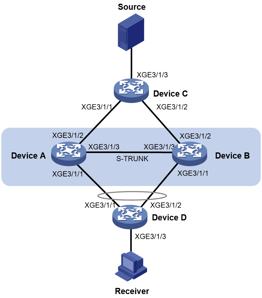
Procedure
1. Assign IP addresses to the interfaces, and configure routes for the devices to reach one another. (Details not shown.)
2. Configure Device A:
# Set the destination UDP port of IPv4 S-Trunk protocol packets.
<DeviceA> system-view
[DeviceA] s-trunk udp-port 2048
# Associate track entry 1 with static BFD session bfd2.
[DeviceA] track 1 bfd static bfd2
# Create a monitor link group and specify member interfaces for it.
[DeviceA] monitor-link group 1
[DeviceA-mtlk-group1] port ten-gigabitethernet 3/1/1 downlink
[DeviceA-mtlk-group1] port ten-gigabitethernet 3/1/2 uplink
[DeviceA-mtlk-group1] quit
# Create a Layer 3 aggregate interface operating in dynamic link aggregation mode, and enable PIM and MLD on the interface.
[DeviceA] interface Route-Aggregation1
[DeviceA-Route-Aggregation1] link-aggregation mode dynamic
[DeviceA-Route-Aggregation1] pim sm
[DeviceA-Route-Aggregation1] mld enable
[DeviceA-Route-Aggregation1] quit
# Specify the local IP address as 1.1.1.1 and the peer IP address as 1.1.1.2 for VSRP to establish VSRP channels, and associate a track entry with VSRP.
[DeviceA] vsrp peer 1
[DeviceA-vsrp-peer-1] peer 1.1.1.2 local 1.1.1.1
[DeviceA-vsrp-peer-1] track 1
[DeviceA-vsrp-peer-1] quit
# Create a VSRP instance.
[DeviceA] vsrp instance 1
[DeviceA-vsrp-instance-1] backup id 1 peer 1
[DeviceA-vsrp-instance-1] bind s-trunk 1 interface Route-Aggregation1
[DeviceA-s-trunk1]quit
# Configure S-Trunk parameters.
[DeviceA] s-trunk id 1
[DeviceA-s-trunk1] s-trunk bfd-session strunk1
[DeviceA-s-trunk1] s-trunk role priority 100
[DeviceA-s-trunk1] s-trunk ip destination 23.0.0.12 source 23.0.0.21
[DeviceA-s-trunk1] quit
# Associate MLD-enabled interface Route-Aggregation 1 with a VSRP instance, configure the role of the S-Trunk member interface as primary, and enable VSRP load sharing on the interface
[DeviceA] interface Route-Aggregation1
[DeviceA-Route-Aggregation1] mld vsrp-instance 1
[DeviceA-Route-Aggregation1] mld vsrp-load-balance restore-delay 30
[DeviceA-Route-Aggregation1] s-trunk 1
[DeviceA-Route-Aggregation1] s-trunk port-role primary
[DeviceA-Route-Aggregation1] quit
# Create a loopback interface to establish VSRP channels.
[DeviceA] interface LoopBack1
[DeviceA-LoopBack1] ip address 1.1.1.1 255.255.255.255
[DeviceA-LoopBack1] ospf 1 area 0.0.0.0
[DeviceA-LoopBack1] pim sm
[DeviceA-LoopBack1] quit
# Configure static BFD to monitor link status for S-Trunk.
[DeviceA] bfd static bfd2 peer-ip 1.1.1.2 source-ip 1.1.1.1 discriminator local 3 remote 4
[DeviceA-bfd-static-session-bfd2] quit
[DeviceA] bfd static strunk1 peer-ip 23.0.0.12 source-ip 23.0.0.21 discriminator local 1 remote 2
[DeviceA-bfd-static-session-strunk1] quit
# Enable IP multicast routing.
[DeviceA] multicast routing
3. Configure Device B:
Configure Device B in the same way Device A is configured. (Details not shown.)
4. Configure Device C:
# Enable IP multicast routing.
<DeviceC> system-view
[DeviceC] multicast routing
[DeviceC-mrib] quit
# Enable PIM-SM on both the upstream and downstream interfaces.
[DeviceC] interface ten-gigabitethernet 3/1/1
[DeviceC-Ten-GigabitEthernet3/1/1] pim sm
[DeviceC-Ten-GigabitEthernet3/1/1] quit
[DeviceC] interface ten-gigabitethernet 3/1/2
[DeviceC-Ten-GigabitEthernet3/1/2] pim sm
[DeviceC-Ten-GigabitEthernet3/1/2] quit
[DeviceC] interface ten-gigabitethernet 3/1/3
[DeviceC-Ten-GigabitEthernet3/1/3] pim sm
[DeviceC-Ten-GigabitEthernet3/1/3] quit
# Configure Device C as the BSR and RP.
[DeviceC] pim
[DeviceC-pim] c-bsr 10.0.0.12
[DeviceC-pim] c-rp 10.0.0.12
[DeviceC-pim] quit
Verifying the configuration
# Verify that Device A (the master) and Device B (the backup) have the same MLD interface and group information. The master and backup devices forward multicast traffic for odd multicast group addresses and even multicast group addresses, respectively.
· On the master:
[DeviceA] display mld interface verbose
Route-Aggregation1(31.0.0.2):
MLD is enabled.
MLD version: 2
Query interval for MLD: 125s
Other querier present time for MLD: 255s
Maximum query response time for MLD: 10s
Last member query interval: 1s
Last member query count: 2
Startup query interval: 31s
Startup query count: 2
General query timer expiry (hh:mm:ss): 00:01:00
Querier for MLD: 31.0.0.2 (This router)
MLD activity: 5935 join(s), 1934 leave(s)
Multicast routing on this interface: Enabled
Robustness: 2
Require-router-alert: Disabled
Fast-leave: Disabled
Startup-query: Off
Other-querier-present-timer-expiry (hh:mm:ss): Off
Authorization: Disabled
Join-by-session: Disabled
User-VLAN-aggregation: Disabled
VSRP instance: 1 (State is master, synchronization is on)
VSRP forward mode: odd (Wait to restore is 30s)
MLD groups reported in total: 4001
· On the backup:
[DeviceB] display mld interface verbose
Route-Aggregation1(31.0.0.1):
MLD is enabled.
MLD version: 2
Query interval for MLD: 125s
Other querier present time for MLD: 255s
Maximum query response time for MLD: 10s
Last member query interval: 1s
Last member query count: 2
Startup query interval: 31s
Startup query count: 2
General query timer expiry (hh:mm:ss): Off
Querier for MLD: 31.0.0.1 (This router)
MLD activity: 6068 join(s), 2067 leave(s)
Multicast routing on this interface: Enabled
Robustness: 2
Require-router-alert: Disabled
Fast-leave: Disabled
Startup-query: On
Other-querier-present-timer-expiry (hh:mm:ss): Off
Authorization: Disabled
Join-by-session: Disabled
User-VLAN-aggregation: Disabled
VSRP instance: 1 (State is backup)
VSRP forward mode: even (Wait to restore is 30s)
MLD groups reported in total: 400
