- Table of Contents
- Related Documents
-
| Title | Size | Download |
|---|---|---|
| 01-Hardware Information and Technical Specifications | 23.60 MB |
Contents
Service module naming conventions
LSCM2SRP6C4Y06A0/LSCM3SRP6C4Y06A0
Restrictions and guidelines for service modules
LSCM2CGS8QS8SF0/LSCM3CGS8QS8SF0/LSCM3CGS8QS8SF0-G3
LSCM2TGS16GPSC0/LSCM2TGS16GPSD0
LSCM2TGS16GP32SD0/LSCM2TGS16GP32SD0-G3
LSCM2GT48SC0/LSCM2GT48SD0/LSCM2GT48SD0-G3
LSCM2GP48SC0/LSCM2GP48SD0/LSCM2GP48SD0-G3
LSCM2GT24GPTSSC0/LSCM2GT24GPTSSD0
LSQM1PWRSPB power module adapter
FAN-80/92-3-A (with two types of fans)
LSQM17510EFAN/LSQM17510EFAN-G3
Making an Ethernet twisted pair cable
1 Chassis
Chassis information
Chassis views
The S7500X-G switch series includes the models in Table1-1.
|
Model |
Product code (PID) |
Description |
|
S7503X-G |
LS-7503X-G |
H3C S7503X-G Ethernet switch chassis |
|
S7503X-M-G |
LS-7503X-M-G |
H3C S7503X-M-G Ethernet switch chassis |
|
S7506X-G |
LS-7506X-G |
H3C S7506X-G Ethernet switch chassis |
|
S7506X-G-PoE |
LS-7506X-G-PoE |
H3C S7506X-G Ethernet switch chassis, PoE |
|
S7506X-G-MF |
LS-7506X-G-MF |
H3C S7506X-G Ethernet switch chassis with multiple fan trays |
|
S7510X-G |
LS-7510X-G |
H3C S7510X-G Ethernet switch chassis |
|
S7510X-G-PoE |
LS-7510X-G-PoE |
H3C S7510X-G Ethernet switch chassis,PoE |
The figures in this section are for illustration only.
S7503X-G
Figure1-1 S7503X-G front panel

|
(2) MPU sections |
|
|
(3) Service module section |
(4) Fan tray section |
S7503X-M-G
Figure1-2 S7503X-M-G front panel
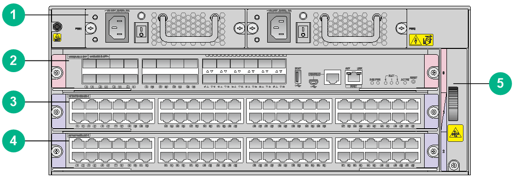
|
(1) Power module section |
(2) MPU section |
|
(3) MPU section/service module section (You can install an MPU or service module in this slot) |
|
|
(4) Service module section |
(5) Fan tray section |
S7506X-G
Figure1-3 S7506X-G front panel
|
(1) Service module sections |
(2) MPU section |
|
(3) Power module sections |
(4) Fan tray section |
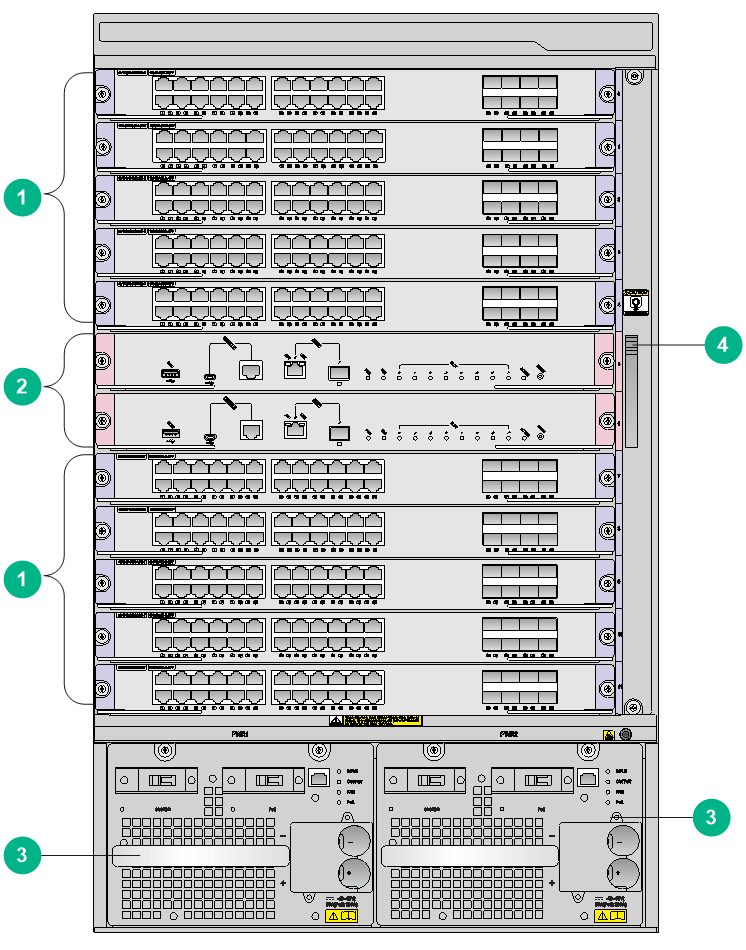
S7506X-G-PoE
Figure1-4 S7506X-G-PoE front panel
|
(1) Service module sections |
(2) MPU section |
|
(3) Power module sections |
(4) Fan tray section |
S7506X-G-MF
Figure1-5 S7506X-G-MF front panel
|
(1) Service module sections |
(2) MPU section |
|
(3) Power module sections |
(4) Fan tray section |
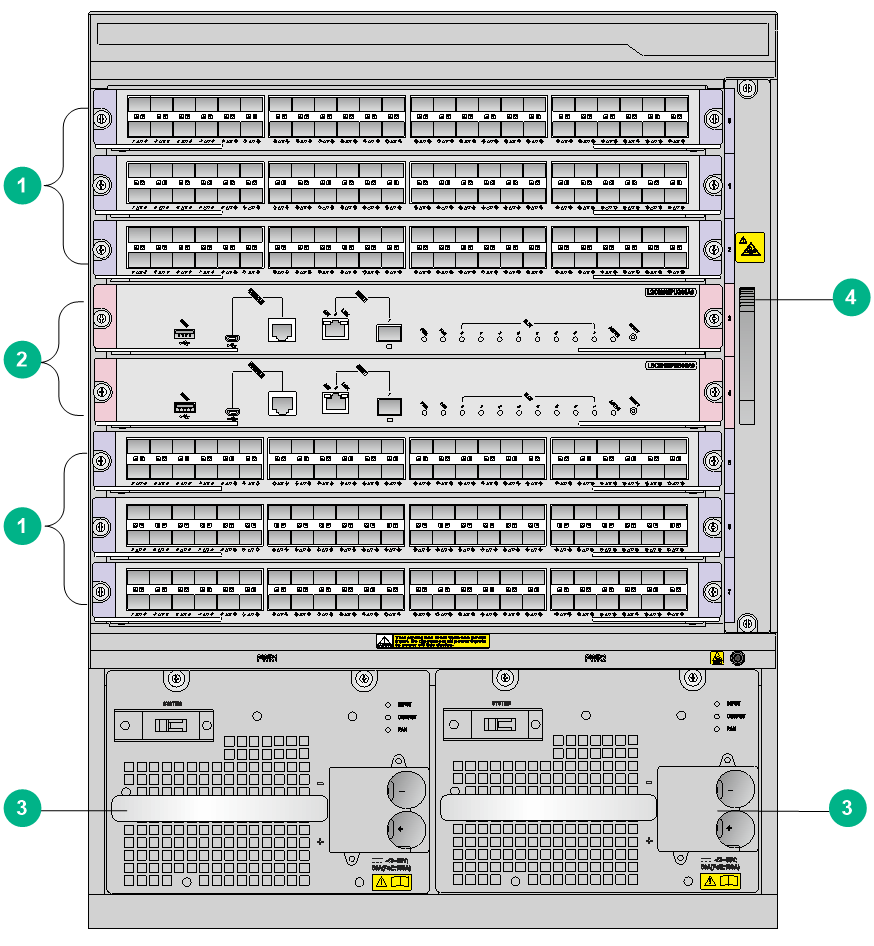
S7510X-G
Figure1-6 S7510X-G front panel
|
(1) Service module sections |
(2) MPU section |
|
(3) Power module sections |
(4) Fan tray section |
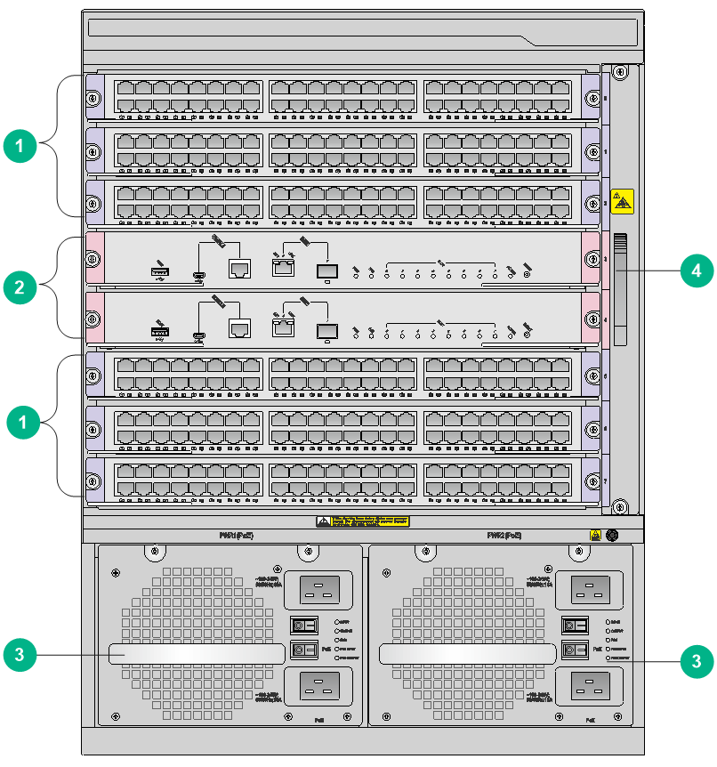
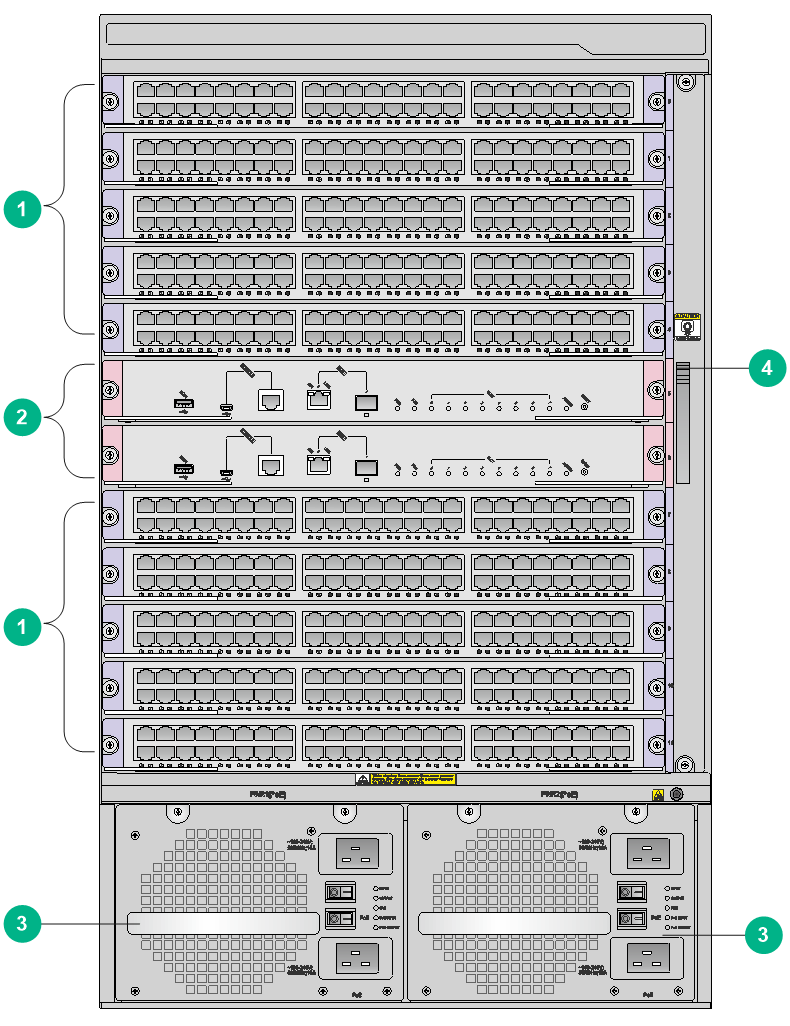
S7510X-G-PoE
Figure1-7 S7510X-G-PoE front panel
|
(1) Service module sections |
(2) MPU section |
|
(3) Power module sections |
(4) Fan tray section |
Slot arrangement
Table1-2 Slot quantity for the removable components
|
Item |
S7503X-G |
S7503X-M-G |
S7506X-G |
S7506X-G-PoE |
S7506X-G-MF |
S7510X-G |
S7510X-G-PoE |
|
MPU slots |
2 |
1 (+1) |
2 |
2 |
2 |
2 |
2 |
|
Service module slots |
3 |
1 (+1) |
6 |
6 |
6 |
10 |
10 |
|
Power module slots |
2 |
2 |
2 |
2 |
2 |
2 |
2 |
|
Fan tray slots |
1 |
1 |
1 |
1 |
3 |
1 |
1 |
Figure1-8 S7503X-G slot arrangement
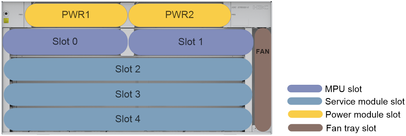
Figure1-9 S7503X-M-G slot arrangement
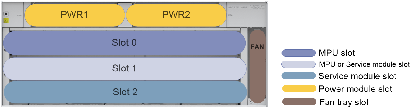
Figure1-10 S7506X-G/S7506X-G-PoE/S7506X-G-MF slot arrangement (S7506X-G as an example)
The S7506X-G-MF switch is designed with multiple fan tray slots.
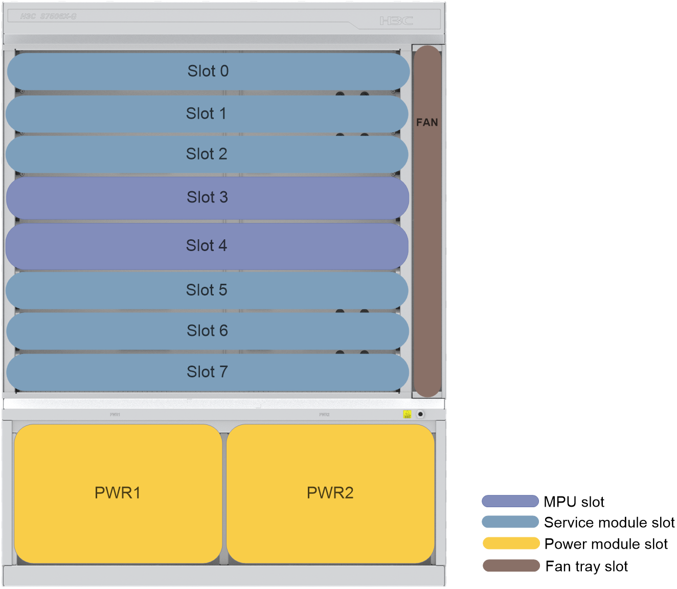
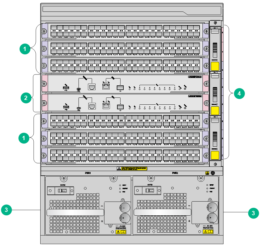
Figure1-11 S7510X-G/S7510X-G-PoE
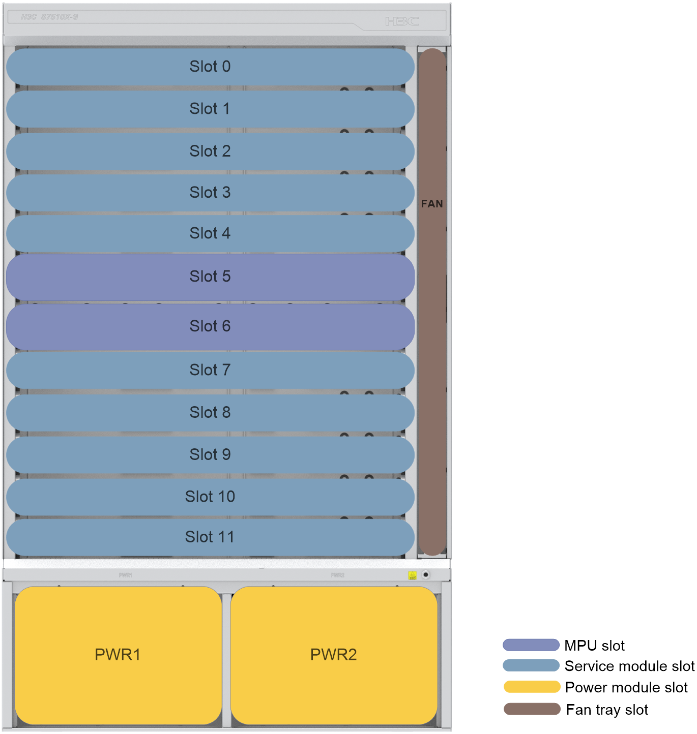
Table1-3 describes the slot arrangement for the removable components.
Table1-3 Slot arrangement for the removable components
|
Model |
MPU |
Service module |
Power module |
Fan tray |
|
S7503X-G |
Slots 0 and 1 |
Slots 2 to 4 |
PWR1 and PWR2 |
FAN |
|
S7503X-M-G |
Slots 0 and 1 |
Slots 1 and 2 |
PWR1 and PWR2 |
FAN |
|
S7506X-G/S7506X-G-PoE/S7506X-G-MF |
Slots 3 and 4 |
Slots 0 to 2 Slots 5 and 6 |
PWR1 and PWR2 |
FAN 0 to FAN 2 |
|
S7510X-G/S7510X-G-PoE |
Slots 5 and 6 |
Slots 0 to 4 Slots 7 to 11 |
PWR1 and PWR2 |
FAN |
Chassis specifications
Table1-4 Chassis specifications
|
Item |
S7503X-G |
S7503X-M-G |
S7506X-G/S7506X-G-PoE/S7506X-G-MF |
S7510X-G/S7510X-G-PoE |
|
Power supply mode |
· AC · Low-voltage DC |
· AC · Low-voltage DC |
· AC · Low-voltage DC · High-voltage DC |
· AC · Low-voltage DC · High-voltage DC |
|
Product compliance |
· Safety standards · EMC standards |
· Safety standards · EMC standards |
· Safety standards · EMC standards |
· Safety standards · EMC standards |
|
MPU redundancy |
1+1 |
1+1 |
1+1 |
1+1 |
|
Power module redundancy |
1+1 |
1+1 |
1+1 |
1+1 |
|
Heat dissipation method |
Air cooling |
Air cooling |
Air cooling |
Air cooling |
|
Maximum number of 100GE ports |
24 |
16 |
48 |
80 |
|
Maximum number of 40GE ports |
24 |
16 |
48 |
80 |
|
Maximum number of 25GE ports |
96 |
64 |
192 |
320 |
|
Maximum number of 10GE ports |
144 |
96 |
288 |
480 |
|
Maximum number of GE ports |
144 |
96 |
288 |
480 |
|
Maximum PoE power |
N/A |
N/A |
S7506X-G: N/A S7506X-G-PoE: 2800 W S7506X-G-MF: N/A |
S75010X-G: N/A S7510X-G-PoE: 2800 W |
Weights and dimensions
Table1-5 Chassis weights and dimensions
|
Model |
Net weight (without package materials) |
Net weight (with package materials) |
Max weight (fully configured) |
Height |
Width |
Depth |
|
S7503X-G |
16.60 kg (36.60 lb) |
20.20 kg (44.53 lb) |
< 35 kg (77.16 lb) |
Without package materials |
||
|
216 mm (8.50 in)/5 RUs |
436 mm (17.17 in) |
420 mm (16.54 in) |
||||
|
With package materials |
||||||
|
375 mm (14.76 in) |
585 mm (23.03 in) |
600 mm (23.62 in) |
||||
|
S7503X-M-G |
14.20 kg (31.31 lb) |
15.35 kg (33.84 lb) |
< 28 kg (61.73 lb) |
Without package materials |
||
|
175 mm (6.89 in)/4 RUs |
436 mm (17.17 in) |
420 mm (16.54 in) |
||||
|
With package materials |
||||||
|
330 mm (12.99 in) |
600 mm (23.62 in) |
585 mm (23.03 in) |
||||
|
S7506X-G |
35.00 kg (77.16 lb) |
44.45 kg (97.99 lb) |
< 75 kg (165.34 lb) |
Without package materials |
||
|
575 mm (22.64 in)/13 RUs |
436 mm (17.17 in) |
420 mm (16.54 in) |
||||
|
With package materials |
||||||
|
750 mm (29.53 in) |
675 mm (26.57 in) |
630 mm (24.80 in) |
||||
|
S7506X-G-PoE |
35.50 kg (78.26 lb) |
40.70 kg (89.73 lb) |
< 80 kg (176.37 lb) |
Without package materials |
||
|
575 mm (22.64 in)/13 RUs |
436 mm (17.17 in) |
420 mm (16.54 in) |
||||
|
With package materials |
||||||
|
750 mm (29.53 in) |
665 mm (26.18 in) |
610 mm (24.02 in) |
||||
|
S7506X-G-MF |
35.50 kg (78.26 lb) |
46.50 kg (102.51 lb) |
< 75 kg (165.34 lb) |
Without package materials |
||
|
575 mm (22.64 in)/13 RUs |
436 mm (17.17 in) |
420 mm (16.54 in) |
||||
|
With package materials |
||||||
|
750 mm (29.53 in) |
675 mm (26.57 in) |
630 mm (24.80 in) |
||||
|
S7510X-G |
47.00 kg (103.62 lb) |
63.35 kg (139.66 lb) |
< 95 kg (209.44 lb) |
Without package materials |
||
|
708 mm (27.87 in)/16 RUs |
436 mm (17.17 in) |
420 mm (16.54 in) |
||||
|
With package materials |
||||||
|
985 mm (38.78 in) |
800 mm (31.50 in) |
600 mm (23.62 in) |
||||
|
S7510X-G-PoE |
48.00 kg (105.82 lb) |
66.35 kg (146.27 lb) |
< 100 kg (220.46 lb) |
Without package materials |
||
|
708 mm (27.87 in)/16 RUs |
436 mm (17.17 in) |
420 mm (16.54 in) |
||||
|
With package materials |
||||||
|
985 mm (38.78 in) |
800 mm (31.50 in) |
600 mm (23.62 in) |
||||
|
|
NOTE: · A rack unit (RU) is 44.45 mm (1.75 in). It is a used as a measurement for the rack height. · Net weight is the chassis weight, excluding the weights of cards, power modules and other removable modules. |
System power consumption
System power consumption
The system power consumption of the switch is the power consumptions of all operating cards and fan trays. It varies by the type and number of the operating cards and the fan tray power consumption.
· The minimum system power consumption is the minimum power consumption of all cards plus the minimum fan tray power consumption.
· The maximum system power consumption is the maximum power consumption of all cards plus the maximum fan tray power consumption.
For example, for an S7506X-G switch that has two LSCM1MPUS06A0 MPUs, three LSCM1GT48SC0 interface modules, and one S7506X-G fan tray, the system power consumption is calculated as follows:
· The minimum system power consumption of the switch is 2 × 64 + 3 × 44 + 24.5 = 284.5 W.
· The maximum system power consumption of the switch is 2 × 92 + 3 × 48 + 42.5 = 370.5 W.
PoE power consumption
The power over Ethernet (PoE) power consumption refers to the power that all powered devices (PDs) receive from the switch.
The maximum PoE power consumption refers to the sum of the power consumption of all PDs when all power interfaces (PIs) are connected to PDs and the maximum PI power is reached. The maximum PoE power consumption is decided by the following items:
· Number of the PoE cards installed on the switch.
· Number of the PIs that each PoE card provides.
· Maximum PoE power that each PoE card can provide.
· Maximum PoE power that each slot on the switch can provide.
The PoE power consumption is 0 if the switch does not supply PoE.
Heat dissipation
Heat dissipation is measured in BTU/h, and 1 W equals 3.4121 BTU/h.
The heat dissipation of a switch depends on its power consumption. To calculate heat dissipation of the switch, assume 90% power consumption is converted to heat, and the efficiency of the power module is 90%. Heat dissipation/hour of the switch is [0.9 × (total power consumption of the cards plus power consumption of the fan tray)]/0.9 × 3.4121.
Table1-6 shows the heat dissipation for each switch model.
|
Model |
Heat dissipation (BTU/h) |
|
S7503X-G |
1504 |
|
S7503X-M-G |
1076 |
|
S7506X-G/S7506X-G-PoE/S7506X-G-MF |
3352 |
|
S7510X-G/S7510X-G-PoE |
5072 |
Reliability and availability
Table1-7 Reliability and availability
|
Model |
Availability |
Mean Time Between Failure (MTBF) (year) |
Mean time to repair (MTTR) (hour) |
|
S7503X-G |
0.9999980 |
59.1 |
1.0 |
|
S7503X-M-G |
0.9999982 |
61.8 |
1.0 |
|
S7506X-G/S7506X-G-PoE/S7506X-G-MF |
0.9999970 |
38.2 |
1.0 |
|
S7510X-G/S7510X-G-PoE |
0.9999990 |
111.6 |
1.0 |
Environmental specifications
Table1-8 Environmental specifications
|
Item |
Operating |
Storage |
|
Temperature |
0°C to 45°C (32°F to 113°F) |
–40°C to +70°C (–40°F to +158°F) |
|
Relative humidity |
5% to 95%, noncondensing |
5% to 95%, noncondensing |
|
Altitude |
–60 m to +5000 m (–196.85 ft to +16404.20 ft) The maximum acceptable temperature decreases by 0.33°C (32.59°F) for every 100 m (328.08 ft) increase in altitude from Tmax@0m. |
–60 m to +5000 m (–196.85 ft to +16404.20 ft) |
Noise
The switch uses fan trays that can adjust the fan speed automatically based on the device temperature. The sound pressure levels vary by fan speed. For more information, see Table1-9.
Table1-9 Sound pressure levels
|
Model |
Sound pressure level when the fan tray operates at low speed |
Sound pressure level when the fan tray operates at middle speed |
Sound pressure level when the fan tray operates at full speed |
|
S7503X-G |
52.2 dBA |
54.0 dBA |
56.0 dBA |
|
S7503X-M-G |
49.8 dBA |
51.6 dBA |
56.7 dBA |
|
S7506X-G/S7506X-G-PoE/S7506X-G-MF |
53.6 dBA |
56.2 dBA |
57.7 dBA |
|
S7510X-G/S7510X-G-PoE |
53.5 dBA |
55.8 dBA |
56.7 dBA |
Rack requirements
The switch is applicable to all 19-inch standard racks. For information about how to select and install a rack, see Universal Cabinet and Accessories Installation Guide.
Slide rails
No slide rails are shipped with the switch. Select slide rails for the switch as required. Table1-10 describes the slide rails available for the switch.
Table1-10 Slide rails available for the switch
|
Part No. |
Slide rail model |
Adjustment range |
Load bearing capacity |
Occupied space |
Applicable rack depth |
Applicable switch model |
|
0231AJE5 |
RL-1U-A |
380 mm to 630 mm (14.96 in to 24.80 in) |
200 kg (440.92 lb) |
1 U |
0.6 m (1.97 ft), 0.8 m (2.62 ft) |
All S7500X-G switch models |
|
0231A0PL |
LSTM2KSGD0 |
500 mm to 800 mm (19.69 in to 31.50 in) |
400 kg (881.83 lb) |
2 U |
0.8 m (2.62 ft), 1.0 m (3.28 ft) |
All S7500X-G switch models |
|
0231A4EK |
LSXM1BSR |
630 mm to 900 mm (24.80 in to 35.43 in) |
400 kg (881.83 lb) |
1 U |
1.0 m (3.28 ft), 1.2 m (3.94 ft) |
All S7500X-G switch models |
|
|
NOTE: The applicable rack depths in Figure1-11 are for your reference only. Before you install slide rails, make sure the rack depth is in the adjustment range of the slide rails. |
2 Cards
The switch supports varieties of cards that are different in power consumptions. For a same card, the power consumption varies by its state.
· The minimum power consumption of a card refers to the power consumed by the card when it is running with all its ports down and its fiber ports not installed with transceiver modules.
· The typical power consumption of a card refers to the power consumed by the card when it is running with 50% of its ports connected and at 50% load.
· The maximum power consumption of a card refers to the power consumed by the card when it is running with all of its ports connected and at full load.
|
|
NOTE: Card dimensions are expressed in the Height (H) × Width (W) × Depth (D) format: · Height—Height of the front panel of the card. · Width—Width of the front panel of the card. · Depth—Depth from the front panel of the card to the connector. |
|
|
NOTE: · For information about transceiver modules and cables available for the cards, see H3C S7500X-G Switch Series Cards and Transceiver Modules Compatibility Matrixes. · To verify compatibility of a card with the host and software version you are using, see the card manuals. |
Naming conventions
MPU naming conventions
Figure2-1 MPU naming conventions
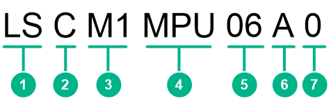
Table2-1 MPU naming conventions
|
No. |
Description |
|
1 |
Product line. LS represents the switch product line. |
|
2 |
Product series. C represents the S7500X-G switch series. |
|
3 |
Distinguisher. |
|
4 |
Module type. Values include MPU, SRP, or SUP. |
|
5 |
Applicable switch models. 06 represents that the MPU is applicable to the S7506X-G and S7506X-G-PoE switches. |
|
6 |
MPU type. |
|
7 |
Extended attributes. |
Service module naming conventions
Figure2-2 Service module naming conventions
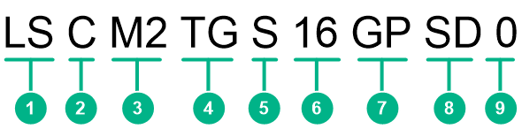
Table2-2 Service module naming conventions
|
No. |
Description |
|
1 |
Product line. LS represents the switch product line. |
|
2 |
Product series. C represents the S7500X-G switch series. |
|
3 |
Distinguisher. |
|
4 |
Primary interface rate of the service module. |
|
5 |
Primary interface type of the service module. |
|
6 |
Primary interface quantity of the service module. |
|
7 |
Optional. Secondary interface type of the service module. |
|
8 |
Service module type. |
|
9 |
Extended attributes. |
MPUs
You can install one MPU, or two MPUs for redundancy on the switch. When you install two MPUs on the switch (except for the S7503X-M-G), make sure the two MPUs are the same model.
For the S7503X-M-G switch, only the following MPUs can be installed together:
· LSCM2CGP24TSSC0 and LSCM2CGT24TSSC0.
· LSCM2CTGS12GPSC0 and LSCM2CTGS12GTSC0.
|
|
NOTE: · Among the management Ethernet ports on an LSCM1SUP03A0, LSCM3SUP03A0, LSCM2SUP03B0, LSCM1MPUS06A0, LSCM2MPUS06AS0, LSCM3MPUS06A0, LSCM3MPUS10B0, LSCM3MPUS10C0, LSCM2SRP6C4Y06A0, or LSCM3SRP6C4Y06A0 MPU, only network management port 0 is available during the startup of the switch. · To connect an SFP management Ethernet port on the MPUs, make sure the peer port operates at 1000 Mbps in full-duplex mode. · The USB ports on the MPUs do not support USB extension cables. · For the S7503X-M-G switch, you can install an MPU or service module in slot 1. |
LSCM1MPUS06A0/LSCM3MPUS06A0
View
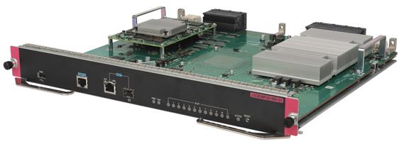
Figure2-3 MPU view (LSCM1MPUS06A0 as an example)
Technical specifications
Table2-3 Technical specifications
|
Item |
LSCM1MPUS06A0 |
LSCM3MPUS06A0 |
|
Net weight |
3.40 kg (7.50 lb) |
3.45 kg (7.61 lb) |
|
Dimensions (H × W × D) |
45 × 399 × 355 mm (1.77 × 15.71 × 13.98 in) |
|
|
Power consumption |
· Minimum: 64 W · Typical: 76 W · Maximum: 92 W |
· Minimum: 68 W · Typical: 80 W · Maximum: 98 W |
|
SDRAM |
2 GB |
4 GB |
|
Flash |
1 GB |
2 GB |
|
NVRAM |
1 MB |
|
|
Connector type |
· RJ-45 · LC · USB (Type A) |
|
|
Ports |
· 1 × console port · 1 × USB console port · 2 × network management ports (one RJ-45 port and one SFP port) · 1 × primary USB port |
|
|
Port transmission speed |
· Console port: 9600 bps (default) to 115200 bps · USB console port: ≤ 115200 bps (default: 9600 bps) · RJ-45 management port: 10/100/1000 Mbps, half/full duplex · SFP management port: 1000 Mbps |
|
|
Hot swapping |
Supported |
|
|
Applicable switch models |
LSCM1MPUS06A0: S7506X-G/S7506X-G-PoE LSCM3MPUS06A0: S7506X-G/S7506X-G-PoE/S7506X-G-MF |
|
Ports and LEDs
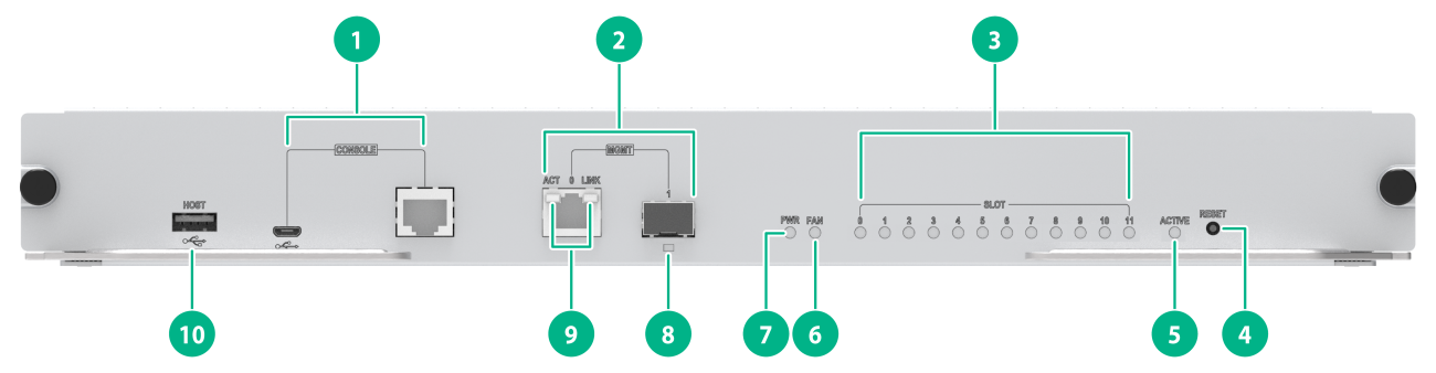
Figure2-4 Front panel
|
(1) Console ports |
(2) Network management ports |
|
(3) Card status LEDs (SLOT) |
(4) Reset button (RESET) |
|
(5) MPU active/standby status LED (ACTIVE) |
(6) Fan tray status LED (FAN) |
|
(7) Power module status LED (PWR) |
(8) SFP fiber management Ethernet port LED (LINK/ACT) |
|
(9) 10/100/1000BASE-T copper management Ethernet port LEDs (LINK and ACT) |
(10) USB port |
|
LED |
Status |
Description |
|
10/100/1000BASE-T copper management Ethernet port LEDs |
LINK: Steady on ACT: Flashing |
A link is present, and the port is receiving or sending data. |
|
LINK: Steady on ACT: Off |
A link is present. |
|
|
LINK: Off ACT: Off |
No link is present. |
|
|
SFP fiber management Ethernet port LED |
Flashing |
A link is present, and the port is receiving or sending data. |
|
Steady on |
A link is present. |
|
|
Off |
No link is present. |
|
|
Power module status LED |
Steady green |
All power modules are operating correctly. |
|
Steady red |
A power module is not outputting power because one of the following conditions exists: · The power module is faulty or switched off. · The power cord is disconnected. · The external power supply system has a power outage. |
|
|
Off |
· No power modules are installed in the chassis. · No power modules are outputting power because one of the following conditions exists: ¡ The power modules are faulty or switched off. ¡ The power cords are disconnected. ¡ The external power supply system has a power outage. |
|
|
Fan tray status LED |
Steady green |
The fan tray is operating correctly. |
|
Steady red |
A fan problem has occurred or the fan tray is not in position. |
|
|
Off |
The switch is not powered on. |
|
|
Card status LED |
Flashing green |
The card is operating correctly. |
|
Flashing green (four times per second) |
The card is loading software. If the LED keeps in this state, the software version running on the switch is not compatible with the card. |
|
|
Steady red |
The card is starting up or faulty. |
|
|
Flashing red |
The temperature of the card has exceeded the upper warning threshold or has dropped below the lower warning threshold. |
|
|
Off |
No card is present. |
|
|
MPU active/standby state LED |
On |
The MPU is in active state. |
|
Off |
· The MPU is in standby state. · The MPU is faulty. To further determine the MPU status, see the card status LED. |
|
|
NOTE: Before the active MPU starts up, all card LEDs are off. The table describes the card LED status after the active MPU starts up. |
Table2-5 Button description
|
Button mark |
Name |
Description |
|
RESET |
Reset button |
To reset the MPU, press the reset button. In a single MPU configuration, pressing the reset button on the MPU triggers not only a reset of the MPU but also a restart of the entire device. In a dual-MPU configuration, pressing the reset button on the active MPU triggers an active/standby MPU switchover. If you press the reset button on the standby MPU, only the standby MPU will be reset without causing the entire device to restart. |
LSCM3MPUS06A0-G3
View
Figure2-5 MPU view
Technical specifications
Table2-6 Technical specifications
|
Item |
LSCM3MPUS06A0-G3 |
|
Net weight |
3.25 kg (7.16 lb) |
|
Dimensions (H × W × D) |
45 × 399 × 355 mm (1.77 × 15.71 × 13.98 in) |
|
Power consumption |
· Minimum: 64 W · Typical: 68 W · Maximum: 81 W |
|
SDRAM |
4 GB |
|
Flash |
8 GB |
|
NVRAM |
1 MB |
|
Connector type |
· RJ-45 · LC · USB (Type A) |
|
Ports |
· 1 × console port · 2 × network management ports (one RJ-45 port and one SFP port) · 1 × primary USB port |
|
Port transmission speed |
· Console port: 9600 bps (default) to 115200 bps · RJ-45 management port: 10/100/1000 Mbps, half/full duplex · SFP management port: 1000 Mbps |
|
Hot swapping |
Supported |
|
Applicable switch models |
S7506X-G, S7506X-G-PoE, S7506X-G-MF |
Ports and LEDs
Figure2-6 Front panel
|
(1) Console port |
(2) Network management ports |
|
(3) Card status LEDs (SLOT) |
(4) Reset button (RESET) |
|
(5) MPU active/standby status LED (ACTIVE) |
(6) Fan tray status LED (FAN) |
|
(7) Power module status LED (PWR) |
(8) SFP fiber management Ethernet port LED (LINK/ACT) |
|
(9) 10/100/1000BASE-T copper management Ethernet port LEDs (LINK and ACT) |
(10) USB port |
Table2-7 LED description
|
LED |
Status |
Description |
|
10/100/1000BASE-T copper management Ethernet port LEDs |
LINK: Steady on ACT: Flashing |
A link is present, and the port is receiving or sending data. |
|
LINK: Steady on ACT: Off |
A link is present. |
|
|
LINK: Off ACT: Off |
No link is present. |
|
|
SFP fiber management Ethernet port LED |
Flashing |
A link is present, and the port is receiving or sending data. |
|
Steady on |
A link is present. |
|
|
Off |
No link is present. |
|
|
Power module status LED |
Steady green |
All power modules are operating correctly. |
|
Steady red |
A power module is not outputting power because one of the following conditions exists: · The power module is faulty or switched off. · The power cord is disconnected. · The external power supply system has a power outage. |
|
|
Off |
· No power modules are installed in the chassis. · No power modules are outputting power because one of the following conditions exists: ¡ The power modules are faulty or switched off. ¡ The power cords are disconnected. ¡ The external power supply system has a power outage. |
|
|
Fan tray status LED |
Steady green |
The fan tray is operating correctly. |
|
Steady red |
A fan problem has occurred or the fan tray is not in position. |
|
|
Off |
The switch is not powered on. |
|
|
Card status LED |
Flashing green |
The card is operating correctly. |
|
Flashing green (four times per second) |
The card is loading software. If the LED keeps in this state, the software version running on the switch is not compatible with the card. |
|
|
Steady red |
The card is starting up or faulty. |
|
|
Flashing red |
The temperature of the card has exceeded the upper warning threshold or has dropped below the lower warning threshold. |
|
|
Off |
No card is present. |
|
|
MPU active/standby state LED |
On |
The MPU is in active state. |
|
Off |
· The MPU is in standby state. · The MPU is faulty. To further determine the MPU status, see the card status LED. |
|
|
NOTE: Before the active MPU starts up, all card LEDs are off. The table describes the card LED status after the active MPU starts up. |
Table2-8 Button description
|
Button mark |
Name |
Description |
|
RESET |
Reset button |
To reset the MPU, press the reset button. In a single MPU configuration, pressing the reset button on the MPU triggers not only a reset of the MPU but also a restart of the entire device. In a dual-MPU configuration, pressing the reset button on the active MPU triggers an active/standby MPU switchover. If you press the reset button on the standby MPU, only the standby MPU will be reset without causing the entire device to restart. |
LSCM1SUP03A0/LSCM3SUP03A0
View
Figure2-7 MPU view (LSCM1SUP03A0 as an example)
Technical specifications
Table2-9 Technical specifications
|
Item |
LSCM1SUP03A0 |
LSCM3SUP03A0 |
|
Net weight |
1.50 kg (3.31 lb) |
1.55 kg (3.42 lb) |
|
Dimensions (H × W × D) |
45 × 199 × 355 mm (1.77 × 7.83 × 13.98 in) |
|
|
Power consumption |
· Minimum: 19 W · Typical: 20 W · Maximum: 23 W |
· Minimum: 23 W · Typical: 24 W · Maximum: 29 W |
|
SDRAM |
2 GB |
4 GB |
|
Flash |
1 GB |
2 GB |
|
NVRAM |
1 MB |
|
|
Connector type |
· RJ-45 · LC · USB (Type A) |
|
|
Ports |
· 1 × console port · 1 × USB console port · 2 × network management ports (one RJ-45 port and one SFP port) · 1 × primary USB port |
|
|
Port transmission speed |
· Console port: 9600 bps (default) to 115200 bps · USB console port: ≤ 115200 bps (default: 9600 bps) · RJ-45 management port: 10/100/1000 Mbps, half/full duplex · SFP management port: 1000 Mbps |
|
|
Hot swapping |
Supported |
|
|
Applicable switch models |
S7503X-G |
|
Ports and LEDs
Figure2-8 Front panel
|
(1) Console ports |
(2) Network management ports |
|
(3) Card status LEDs (SLOT) |
(4) Reset button (RESET) |
|
(5) MPU active/standby status LED (ACTIVE) |
(6) Fan tray status LED (FAN) |
|
(7) Power module status LED (PWR) |
(8) SFP fiber management Ethernet port LED (LINK/ACT) |
|
(9) 10/100/1000BASE-T copper management Ethernet port LEDs (LINK and ACT) |
(10) USB port |
Table2-10 LED description
|
LED |
Status |
Description |
|
10/100/1000BASE-T copper management Ethernet port LEDs |
LINK: Steady on ACT: Flashing |
A link is present, and the port is receiving or sending data. |
|
LINK: Steady on ACT: Off |
A link is present. |
|
|
LINK: Off ACT: Off |
No link is present. |
|
|
SFP fiber management Ethernet port LED |
Flashing |
A link is present, and the port is receiving or sending data. |
|
Steady on |
A link is present. |
|
|
Off |
No link is present. |
|
|
Power module status LED |
Steady green |
All power modules are operating correctly. |
|
Steady red |
A power module is not outputting power because one of the following conditions exists: · The power module is faulty or switched off. · The power cord is disconnected. · The external power supply system has a power outage. |
|
|
Off |
· No power modules are installed in the chassis. · No power modules are outputting power because one of the following conditions exists: ¡ The power modules are faulty or switched off. ¡ The power cords are disconnected. ¡ The external power supply system has a power outage. |
|
|
Fan tray status LED |
Steady green |
The fan tray is operating correctly. |
|
Steady red |
A fan problem has occurred or the fan tray is not in position. |
|
|
Off |
The switch is not powered on. |
|
|
Card status LED |
Flashing green |
The card is operating correctly. |
|
Flashing green (four times per second) |
The card is loading software. If the LED keeps in this state, the software version running on the switch is not compatible with the card. |
|
|
Steady red |
The card is starting up or faulty. |
|
|
Flashing red |
The temperature of the card has exceeded the upper warning threshold or has dropped below the lower warning threshold. |
|
|
Off |
No card is present. |
|
|
MPU active/standby state LED |
On |
The MPU is in active state. |
|
Off |
· The MPU is in standby state. · The MPU is faulty. To further determine the MPU status, see the card status LED. |
|
|
NOTE: Before the active MPU starts up, all card LEDs are off. The table describes the card LED status after the active MPU starts up. |
Table2-11 Button description
|
Button mark |
Name |
Description |
|
RESET |
Reset button |
To reset the MPU, press the reset button. In a single MPU configuration, pressing the reset button on the MPU triggers not only a reset of the MPU but also a restart of the entire device. In a dual-MPU configuration, pressing the reset button on the active MPU triggers an active/standby MPU switchover. If you press the reset button on the standby MPU, only the standby MPU will be reset without causing the entire device to restart. |
LSCM2SUP03B0
View
Figure2-9 MPU view
Technical specifications
Table2-12 Technical specifications
|
Item |
Specification |
|
Net weight |
1.50 kg (3.31 lb) |
|
Dimensions (H × W × D) |
45 × 199 × 355 mm (1.77 × 7.83 × 13.98 in) |
|
Power consumption |
· Minimum: 9 W · Typical: 10 W · Maximum: 16 W |
|
SDRAM |
4 GB |
|
Flash |
4 GB |
|
NVRAM |
1 MB |
|
Connector type |
· RJ-45 · LC · USB (Type A) |
|
Ports |
· 1 × console port · 1 × USB console port · 2 × network management ports (one RJ-45 port and one SFP port) · 1 × primary USB port |
|
Port transmission speed |
· Console port: 9600 bps (default) to 115200 bps · USB console port: ≤ 115200 bps (default: 9600 bps) · RJ-45 management port: 10/100/1000 Mbps, half/full duplex · SFP management port: 1000 Mbps |
|
Hot swapping |
Supported |
|
Applicable switch models |
S7503X-G |
Ports and LEDs
Figure2-10 Front panel
|
(1) Network management ports |
(2) Card status LEDs (SLOT) |
|
(3) Reset button (RESET) |
(4) MPU active/standby status LED (ACTIVE) |
|
(5) Fan tray status LED (FAN) |
(6) Power module status LED (PWR) |
|
(7) 10/100/1000BASE-T copper management Ethernet port LED |
(8) Console ports |
|
(9) SFP fiber management Ethernet port LED |
(10) USB port |
Table2-13 LED description
|
LED |
Status |
Description |
|
Management Ethernet port LED |
Flashing |
A link is present, and the port is receiving or sending data. |
|
Steady on |
A link is present. |
|
|
Off |
No link is present. |
|
|
Power module status LED |
Steady green |
All power modules are operating correctly. |
|
Steady red |
A power module is not outputting power because one of the following conditions exists: · The power module is faulty or switched off. · The power cord is disconnected. · The external power supply system has a power outage. |
|
|
Off |
· No power modules are installed in the chassis. · No power modules are outputting power because one of the following conditions exists: ¡ The power modules are faulty or switched off. ¡ The power cords are disconnected. ¡ The external power supply system has a power outage. |
|
|
Fan tray status LED |
Steady green |
The fan tray is operating correctly. |
|
Steady red |
A fan problem has occurred or the fan tray is not in position. |
|
|
Off |
The switch is not powered on. |
|
|
Card status LED |
Flashing green |
The card is operating correctly. |
|
Flashing green (four times per second) |
The card is loading software. If the LED keeps in this state, the software version running on the switch is not compatible with the card. |
|
|
Steady red |
The card is starting up or faulty. |
|
|
Flashing red |
The temperature of the card has exceeded the upper warning threshold or has dropped below the lower warning threshold. |
|
|
Off |
No card is present. |
|
|
MPU active/standby state LED |
On |
The MPU is in active state. |
|
Off |
· The MPU is in standby state. · The MPU is faulty. To further determine the MPU status, see the card status LED. |
|
|
NOTE: Before the active MPU starts up, all card LEDs are off. The table describes the card LED status after the active MPU starts up. |
Table2-14 Button description
|
Button mark |
Name |
Description |
|
RESET |
Reset button |
To reset the MPU, press the reset button. In a single MPU configuration, pressing the reset button on the MPU triggers not only a reset of the MPU but also a restart of the entire device. In a dual-MPU configuration, pressing the reset button on the active MPU triggers an active/standby MPU switchover. If you press the reset button on the standby MPU, only the standby MPU will be reset without causing the entire device to restart. |
LSCM2CGP24TSSC0
View
Figure2-11 MPU view
Technical specifications
Table2-15 Technical specifications
|
Item |
Specification |
|
Net weight |
3.35 kg (7.39 lb) |
|
Dimensions (H × W × D) |
40 × 399 × 355 mm (1.57 × 15.71 × 13.98 in) |
|
Power consumption |
· Minimum: 23 W · Typical: 30 W · Maximum: 45 W |
|
SDRAM |
2 GB |
|
Flash |
4 GB |
|
NVRAM |
1 MB |
|
Connector type |
· RJ-45 · LC · USB (Type A) |
|
Ports |
· 1 × console port · 1 × USB console port · 1 × network management port · 1 × primary USB port · 4 × SFP+ ports · 24 × SFP ports |
|
Port transmission speed |
· Console port: 9600 bps (default) to 115200 bps · USB console port: ≤ 115200 bps (default: 9600 bps) · Network management port: 10/100/1000 Mbps, half/full duplex · SFP+ port: 10 Gbps, 2.5 Gbps, 1 Gbps · SFP port: 2.5 Gbps, 1 Gbps, 100 Mbps |
|
Hot swapping |
Supported |
|
Applicable switch models |
S7503X-M-G |
Ports and LEDs
Figure2-12 Front panel
|
(1) 1000BASE-X-SFP fiber ports |
(2) 10GBASE-R-SFP+ fiber ports |
|
(3) Copper management Ethernet port LEDs |
(4) Card status LEDs (SLOT) |
|
(5) Reset button (RESET) |
(6) MPU active/standby status LED (ACTIVE) |
|
(7) Power module status LED (PWR) |
(8) Fan tray status LED (FAN) |
|
(9) Network management port |
(10) Console ports |
|
(11) USB port |
(12) 10GBASE-R-SFP+ fiber port LED |
|
(13) 1000BASE-X-SFP fiber port LED |
|
Table2-16 LED description
|
LED |
Status |
Description |
|
Management Ethernet port LEDs |
LINK: Steady on ACT: Flashing |
A link is present, and the port is receiving or sending data. |
|
LINK: Steady on ACT: Off |
A link is present. |
|
|
LINK: Off ACT: Off |
No link is present. |
|
|
Power module status LED |
Steady green |
All power modules are operating correctly. |
|
Steady red |
A power module is not outputting power because one of the following conditions exists: · The power module is faulty or switched off. · The power cord is disconnected. · The external power supply system has a power outage. |
|
|
Off |
· No power modules are installed in the chassis. · No power modules are outputting power because one of the following conditions exists: ¡ The power modules are faulty or switched off. ¡ The power cords are disconnected. ¡ The external power supply system has a power outage. |
|
|
Fan tray status LED |
Steady green |
The fan tray is operating correctly. |
|
Steady red |
A fan problem has occurred or the fan tray is not in position. |
|
|
Off |
The switch is not powered on. |
|
|
Card status LED |
Flashing green |
The card is operating correctly. |
|
Flashing green (four times per second) |
The card is loading software. If the LED keeps in this state, the software version running on the switch is not compatible with the card. |
|
|
Steady red |
The card is starting up or faulty. |
|
|
Flashing red |
The temperature of the card has exceeded the upper warning threshold or has dropped below the lower warning threshold. |
|
|
Off |
No card is present. |
|
|
MPU active/standby state LED |
On |
The MPU is in active state. |
|
Off |
· The MPU is in standby state. · The MPU is faulty. To further determine the MPU status, see the card status LED. |
|
|
SFP+ port LED |
Flashing |
The port is receiving or sending data. |
|
On |
A link is present. |
|
|
Off |
No link is present. |
|
|
SFP port LED |
Flashing |
The port is receiving or sending data. |
|
On |
A link is present. |
|
|
Off |
No link is present. |
|
|
NOTE: Before the active MPU starts up, all card LEDs are off. The table describes the card LED status after the active MPU starts up. |
Table2-17 Button description
|
Button mark |
Name |
Description |
|
RESET |
Reset button |
To reset the MPU, press the reset button. In a single MPU configuration, pressing the reset button on the MPU triggers not only a reset of the MPU but also a restart of the entire device. In a dual-MPU configuration, pressing the reset button on the active MPU triggers an active/standby MPU switchover. If you press the reset button on the standby MPU, only the standby MPU will be reset without causing the entire device to restart. |
LSCM2CGT24TSSC0
View
Figure2-13 MPU view
Technical specifications
Table2-18 Technical specifications
|
Item |
Specification |
|
Net weight |
3.40 kg (7.50 lb) |
|
Dimensions (H × W × D) |
40 × 399 × 355 mm (1.57 × 15.71 × 13.98 in) |
|
Power consumption |
· Minimum: 23 W · Typical: 27 W · Maximum: 41 W |
|
SDRAM |
2 GB |
|
Flash |
4 GB |
|
NVRAM |
1 MB |
|
Connector type |
· RJ-45 · LC · USB (Type A) |
|
Ports |
· 1 × console port · 1 × USB console port · 1 × network management port · 1 × primary USB port · 4 × SFP+ ports · 24 × RJ-45 copper ports |
|
Port transmission speed |
· Console port: 9600 bps (default) to 115200 bps · USB console port: ≤ 115200 bps (default: 9600 bps) · Network management port: 10/100/1000 Mbps, half/full duplex · SFP+ port: 10 Gbps, 2.5 Gbps, 1 Gbps · RJ-45 port: 10/100/1000Mbps |
|
Hot swapping |
Supported |
|
Applicable switch models |
S7503X-M-G |
Ports and LEDs
Figure2-14 Front panel
|
(1) 10/100/1000BASE-T ports |
(2) 10GBASE-R-SFP+ fiber ports |
|
(3) Copper management Ethernet port LEDs |
(4) Card status LEDs (SLOT) |
|
(5) Reset button (RESET) |
(6) MPU active/standby status LED (ACTIVE) |
|
(7) Power module status LED (PWR) |
(8) Fan tray status LED (FAN) |
|
(9) Network management port |
(10) Console ports |
|
(11) USB port |
(12) 10GBASE-R-SFP+ fiber port LED |
|
(13) 10/100/1000BASE-T port LED |
|
Table2-19 LED description
|
LED |
Status |
Description |
|
Management Ethernet port LEDs |
LINK: Steady on ACT: Flashing |
A link is present, and the port is receiving or sending data. |
|
LINK: Steady on ACT: Off |
A link is present. |
|
|
LINK: Off ACT: Off |
No link is present. |
|
|
Power module status LED |
Steady green |
All power modules are operating correctly. |
|
Steady red |
A power module is not outputting power because one of the following conditions exists: · The power module is faulty or switched off. · The power cord is disconnected. · The external power supply system has a power outage. |
|
|
Off |
· No power modules are installed in the chassis. · No power modules are outputting power because one of the following conditions exists: ¡ The power modules are faulty or switched off. ¡ The power cords are disconnected. ¡ The external power supply system has a power outage. |
|
|
Fan tray status LED |
Steady green |
The fan tray is operating correctly. |
|
Steady red |
A fan problem has occurred or the fan tray is not in position. |
|
|
Off |
The switch is not powered on. |
|
|
Card status LED |
Flashing green |
The card is operating correctly. |
|
Flashing green (four times per second) |
The card is loading software. If the LED keeps in this state, the software version running on the switch is not compatible with the card. |
|
|
Steady red |
The card is starting up or faulty. |
|
|
Flashing red |
The temperature of the card has exceeded the upper warning threshold or has dropped below the lower warning threshold. |
|
|
Off |
No card is present. |
|
|
MPU active/standby state LED |
On |
The MPU is in active state. |
|
Off |
· The MPU is in standby state. · The MPU is faulty. To further determine the MPU status, see the card status LED. |
|
|
RJ-45 port LED |
Flashing |
The port is receiving or sending data. |
|
On |
A link is present. |
|
|
Off |
No link is present. |
|
|
SFP+ port LED |
Flashing |
The port is receiving or sending data. |
|
On |
A link is present. |
|
|
Off |
No link is present. |
|
|
NOTE: Before the active MPU starts up, all card LEDs are off. The table describes the card LED status after the active MPU starts up. |
Table2-20 Button description
|
Button mark |
Name |
Description |
|
RESET |
Reset button |
To reset the MPU, press the reset button. In a single MPU configuration, pressing the reset button on the MPU triggers not only a reset of the MPU but also a restart of the entire device. In a dual-MPU configuration, pressing the reset button on the active MPU triggers an active/standby MPU switchover. If you press the reset button on the standby MPU, only the standby MPU will be reset without causing the entire device to restart. |
LSCM2CTGS12GPSC0
View
Figure2-15 MPU view
Technical specifications
Table2-21 Technical specifications
|
Item |
Specification |
|
Net weight |
3.35 kg (7.39 lb) |
|
Dimensions (H × W × D) |
40 × 399 × 355 mm (1.57 × 15.71 × 13.98 in) |
|
Power consumption |
· Minimum: 25 W · Typical: 36 W · Maximum: 53 W |
|
SDRAM |
2 GB |
|
Flash |
4 GB |
|
NVRAM |
1 MB |
|
Connector type |
· RJ-45 · LC · USB (Type A) |
|
Ports |
· 1 × console port · 1 × USB console port · 1 × network management port · 1 × primary USB port · 16 × SFP ports · 12 × SFP+ ports |
|
Port transmission speed |
· Console port: 9600 bps (default) to 115200 bps · USB console port: ≤ 115200 bps (default: 9600 bps) · Network management port: 10/100/1000 Mbps, half/full duplex · SFP+ port: 10 Gbps, 2.5 Gbps, 1 Gbps · SFP port: 1 Gbps, 100 Mbps |
|
Hot swapping |
Supported |
|
Applicable switch models |
S7503X-M-G |
Ports and LEDs
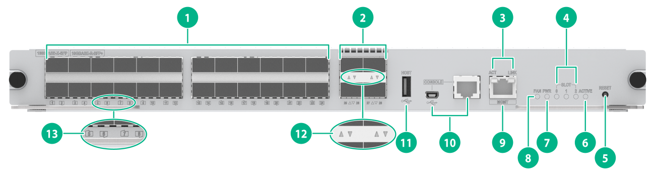
Figure2-16 Front panel
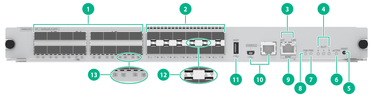
|
(1) 1000BASE-X-SFP fiber ports |
(2) 10GBASE-R-SFP+ fiber ports |
|
(3) Copper management Ethernet port LEDs |
(4) Card status LEDs (SLOT) |
|
(5) Reset button (RESET) |
(6) MPU active/standby status LED (ACTIVE) |
|
(7) Power module status LED (PWR) |
(8) Fan tray status LED (FAN) |
|
(9) Network management port |
(10) Console ports |
|
(11) USB port |
(12) 10GBASE-R-SFP+ fiber port LED |
|
(13) 1000BASE-X-SFP fiber port LED |
|
Table2-22 LED description
|
LED |
Status |
Description |
|
Management Ethernet port LEDs |
LINK: Steady on ACT: Flashing |
A link is present, and the port is receiving or sending data. |
|
LINK: Steady on ACT: Off |
A link is present. |
|
|
LINK: Off ACT: Off |
No link is present. |
|
|
Power module status LED |
Steady green |
All power modules are operating correctly. |
|
Steady red |
A power module is not outputting power because one of the following conditions exists: · The power module is faulty or switched off. · The power cord is disconnected. · The external power supply system has a power outage. |
|
|
Off |
· No power modules are installed in the chassis. · No power modules are outputting power because one of the following conditions exists: ¡ The power modules are faulty or switched off. ¡ The power cords are disconnected. ¡ The external power supply system has a power outage. |
|
|
Fan tray status LED |
Steady green |
The fan tray is operating correctly. |
|
Steady red |
A fan problem has occurred or the fan tray is not in position. |
|
|
Off |
The switch is not powered on. |
|
|
Card status LED |
Flashing green |
The card is operating correctly. |
|
Flashing green (four times per second) |
The card is loading software. If the LED keeps in this state, the software version running on the switch is not compatible with the card. |
|
|
Steady red |
The card is starting up or faulty. |
|
|
Flashing red |
The temperature of the card has exceeded the upper warning threshold or has dropped below the lower warning threshold. |
|
|
Off |
No card is present. |
|
|
MPU active/standby state LED |
On |
The MPU is in active state. |
|
Off |
· The MPU is in standby state. · The MPU is faulty. To further determine the MPU status, see the card status LED. |
|
|
SFP+ port LED |
Flashing |
The port is receiving or sending data. |
|
On |
A link is present. |
|
|
Off |
No link is present. |
|
|
SFP port LED |
Flashing |
The port is receiving or sending data. |
|
On |
A link is present. |
|
|
Off |
No link is present. |
|
|
NOTE: Before the active MPU starts up, all card LEDs are off. The table describes the card LED status after the active MPU starts up. |
Table2-23 Button description
|
Button mark |
Name |
Description |
|
RESET |
Reset button |
To reset the MPU, press the reset button. In a single MPU configuration, pressing the reset button on the MPU triggers not only a reset of the MPU but also a restart of the entire device. In a dual-MPU configuration, pressing the reset button on the active MPU triggers an active/standby MPU switchover. If you press the reset button on the standby MPU, only the standby MPU will be reset without causing the entire device to restart. |
LSCM2CTGS12GTSC0
View
Figure2-17 MPU view
Technical specifications
Table2-24 Technical specifications
|
Item |
Specification |
|
Net weight |
3.40 kg (7.50 lb) |
|
Dimensions (H × W × D) |
40 × 399 × 355 mm (1.57 × 15.71 × 13.98 in) |
|
Power consumption |
· Minimum: 24 W · Typical: 35 W · Maximum: 49 W |
|
SDRAM |
2 GB |
|
Flash |
4 GB |
|
NVRAM |
1 MB |
|
Connector type |
· RJ-45 · LC · USB (Type A) |
|
Ports |
· 1 × console port · 1 × USB console port · 1 × network management port · 1 × primary USB port · 12 × SFP+ ports · 16 × RJ-45 ports |
|
Port transmission speed |
· Console port: 9600 bps (default) to 115200 bps · USB console port: ≤ 115200 bps (default: 9600 bps) · Network management port: 10/100/1000 Mbps, half/full duplex · SFP+ port: 10 Gbps, 2.5 Gbps, 1 Gbps · RJ-45 port: 10/100/1000 Mbps |
|
Hot swapping |
Supported |
|
Applicable switch models |
S7503X-M-G |
Ports and LEDs
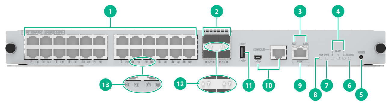
Figure2-18 Front panel
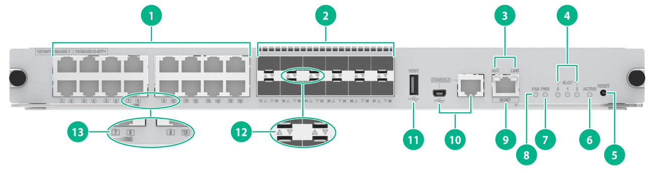
|
(1) 10/100/1000BASE-T ports |
(2) 10GBASE-R-SFP+ fiber ports |
|
(3) Copper management Ethernet port LEDs |
(4) Card status LEDs (SLOT) |
|
(5) Reset button (RESET) |
(6) MPU active/standby status LED (ACTIVE) |
|
(7) Power module status LED (PWR) |
(8) Fan tray status LED (FAN) |
|
(9) Network management port |
(10) Console ports |
|
(11) USB port |
(12) 10GBASE-R-SFP+ fiber port LED |
|
(13) 10/100/1000BASE-T port LED |
|
Table2-25 LED description
|
LED |
Status |
Description |
|
Management Ethernet port LEDs |
LINK: Steady on ACT: Flashing |
A link is present, and the port is receiving or sending data. |
|
LINK: Steady on ACT: Off |
A link is present. |
|
|
LINK: Off ACT: Off |
No link is present. |
|
|
Power module status LED |
Steady green |
All power modules are operating correctly. |
|
Steady red |
A power module is not outputting power because one of the following conditions exists: · The power module is faulty or switched off. · The power cord is disconnected. · The external power supply system has a power outage. |
|
|
Off |
· No power modules are installed in the chassis. · No power modules are outputting power because one of the following conditions exists: ¡ The power modules are faulty or switched off. ¡ The power cords are disconnected. ¡ The external power supply system has a power outage. |
|
|
Fan tray status LED |
Steady green |
The fan tray is operating correctly. |
|
Steady red |
A fan problem has occurred or the fan tray is not in position. |
|
|
Off |
The switch is not powered on. |
|
|
Card status LED |
Flashing green |
The card is operating correctly. |
|
Flashing green (four times per second) |
The card is loading software. If the LED keeps in this state, the software version running on the switch is not compatible with the card. |
|
|
Steady red |
The card is starting up or faulty. |
|
|
Flashing red |
The temperature of the card has exceeded the upper warning threshold or has dropped below the lower warning threshold. |
|
|
Off |
No card is present. |
|
|
MPU active/standby state LED |
On |
The MPU is in active state. |
|
Off |
· The MPU is in standby state. · The MPU is faulty. To further determine the MPU status, see the card status LED. |
|
|
RJ-45 port LED |
Flashing |
The port is receiving or sending data. |
|
On |
A link is present. |
|
|
Off |
No link is present. |
|
|
SFP+ port LED |
Flashing |
The port is receiving or sending data. |
|
On |
A link is present. |
|
|
Off |
No link is present. |
|
|
NOTE: Before the active MPU starts up, all card LEDs are off. The table describes the card LED status after the active MPU starts up. |
Table2-26 Button description
|
Button mark |
Name |
Description |
|
RESET |
Reset button |
To reset the MPU, press the reset button. In a single MPU configuration, pressing the reset button on the MPU triggers not only a reset of the MPU but also a restart of the entire device. In a dual-MPU configuration, pressing the reset button on the active MPU triggers an active/standby MPU switchover. If you press the reset button on the standby MPU, only the standby MPU will be reset without causing the entire device to restart. |
LSCM2MPUS06AS0
View
Figure2-19 MPU view
Technical specifications
Table2-27 Technical specifications
|
Item |
Specification |
|
Net weight |
3.20 kg (7.05 lb) |
|
Dimensions (H × W × D) |
45 × 399 × 355 mm (1.77 × 15.71 × 13.98 in) |
|
Power consumption |
· Minimum: 23 W · Typical: 25 W · Maximum: 31 W |
|
SDRAM |
2 GB |
|
Flash |
4 GB |
|
NVRAM |
1 MB |
|
Connector type |
· RJ-45 · LC · USB (Type A) |
|
Ports |
· 1 × console port · 1 × USB console port · 2 × network management ports (one RJ-45 port and one SFP port) · 1 × primary USB port |
|
Port transmission speed |
· Console port: 9600 bps (default) to 115200 bps · USB console port: ≤ 115200 bps (default: 9600 bps) · RJ-45 management port: 10/100/1000 Mbps, half/full duplex · SFP management port: 1000 Mbps |
|
Hot swapping |
Supported |
|
Applicable switch models |
S7506X-G, S7506X-G-PoE, S7506X-G-MF |
Ports and LEDs
Figure2-20 Front panel

|
(1) Console ports |
(2) Network management ports |
|
(3) Card status LEDs (SLOT) |
(4) Reset button (RESET) |
|
(5) MPU active/standby status LED (ACTIVE) |
(6) Fan tray status LED (FAN) |
|
(7) Power module status LED (PWR) |
(8) SFP fiber management Ethernet port LED (LINK/ACT) |
|
(9) 10/100/1000BASE-T copper management Ethernet port LEDs (LINK and ACT) |
(10) USB port |
Table2-28 LED description
|
LED |
Status |
Description |
|
10/100/1000BASE-T copper management Ethernet port LEDs |
LINK: Steady on ACT: Flashing |
A link is present, and the port is receiving or sending data. |
|
LINK: Steady on ACT: Off |
A link is present. |
|
|
LINK: Off ACT: Off |
No link is present. |
|
|
SFP fiber management Ethernet port LED |
Flashing |
A link is present, and the port is receiving or sending data. |
|
Steady on |
A link is present. |
|
|
Off |
No link is present. |
|
|
Power module status LED |
Steady green |
All power modules are operating correctly. |
|
Steady red |
A power module is not outputting power because one of the following conditions exists: · The power module is faulty or switched off. · The power cord is disconnected. · The external power supply system has a power outage. |
|
|
Off |
· No power modules are installed in the chassis. · No power modules are outputting power because one of the following conditions exists: ¡ The power modules are faulty or switched off. ¡ The power cords are disconnected. ¡ The external power supply system has a power outage. |
|
|
Fan tray status LED |
Steady green |
The fan tray is operating correctly. |
|
Steady red |
A fan problem has occurred or the fan tray is not in position. |
|
|
Off |
The switch is not powered on. |
|
|
Card status LED |
Flashing green |
The card is operating correctly. |
|
Flashing green (four times per second) |
The card is loading software. If the LED keeps in this state, the software version running on the switch is not compatible with the card. |
|
|
Steady red |
The card is starting up or faulty. |
|
|
Flashing red |
The temperature of the card has exceeded the upper warning threshold or has dropped below the lower warning threshold. |
|
|
Off |
No card is present. |
|
|
MPU active/standby state LED |
On |
The MPU is in active state. |
|
Off |
· The MPU is in standby state. · The MPU is faulty. To further determine the MPU status, see the card status LED. |
|
|
NOTE: Before the active MPU starts up, all card LEDs are off. The table describes the card LED status after the active MPU starts up. |
Table2-29 Button description
|
Button mark |
Name |
Description |
|
RESET |
Reset button |
To reset the MPU, press the reset button. In a single MPU configuration, pressing the reset button on the MPU triggers not only a reset of the MPU but also a restart of the entire device. In a dual-MPU configuration, pressing the reset button on the active MPU triggers an active/standby MPU switchover. If you press the reset button on the standby MPU, only the standby MPU will be reset without causing the entire device to restart. |
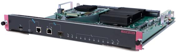
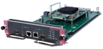
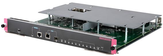
LSCM2SRP6C4Y06A0/LSCM3SRP6C4Y06A0
View
Figure2-21 MPU view (LSCM2SRP6C4Y06A0 as an example)
Technical specifications
Table2-30 Technical specifications
|
Item |
LSCM2SRP6C4Y06A0 |
LSCM3SRP6C4Y06A0 |
|
Net weight |
3.35 kg (7.39 lb) |
3.40 kg (7.50 lb) |
|
Dimensions (H × W × D) |
45 × 399 × 355 mm (1.77 × 15.71 × 13.98 in) |
|
|
Power consumption |
· Minimum: 77 W · Typical: 90 W · Maximum: 137 W |
· Minimum: 77 W · Typical: 90 W · Maximum: 140 W |
|
SDRAM |
8 GB |
8 GB |
|
Flash |
8 GB |
2 GB |
|
NVRAM |
1 MB |
|
|
Connector type |
· RJ-45 · LC · USB (Type A) |
|
|
Ports |
· 1 × console port · 1 × USB console port · 2 × network management ports (one RJ-45 port and one SFP port) · 4 × SFP28 ports · 6 × QSFP28 ports |
|
|
Port transmission speed |
· Console port: 9600 bps (default) to 115200 bps · RJ-45 management port: 10/100/1000 Mbps, half/full duplex · SFP management port: 1000 Mbps · SFP28 port: 25 Gbps · QSFP28 port: 100 Gbps |
|
|
Hot swapping |
Supported |
|
|
Applicable switch models |
S7506X-G, S7506X-G-PoE, S7506X-G-MF |
|
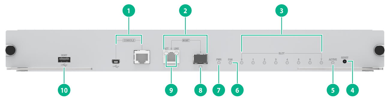
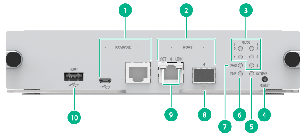
Ports and LEDs
Figure2-22 Front panel
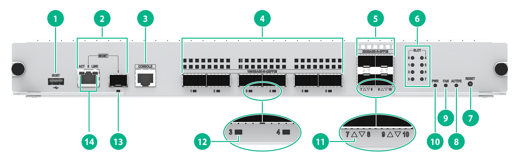
|
(1) USB port |
(2) Network management ports |
|
(3) Console port |
(4) 100GBASE-R-QSFP28 fiber ports |
|
(5) 25GBASE-R-SFP28 fiber ports |
(6) Card status LEDs (SLOT) |
|
(7) Reset button (RESET) |
(8) MPU active/standby status LED (ACTIVE) |
|
(9) Fan tray status LED (FAN) |
(10) Power module status LED (PWR) |
|
(11) 25GBASE-R-SFP28 fiber port LED |
(12) 100GBASE-R-QSFP28 fiber port LED |
|
(13) SFP fiber management Ethernet port LED |
(14) Copper management Ethernet port LEDs |
Table2-31 LED description
|
LED |
Status |
Description |
|
Management Ethernet port LED |
Flashing |
A link is present, and the port is receiving or sending data. |
|
Steady on |
A link is present. |
|
|
Off |
No link is present. |
|
|
Power module status LED |
Steady green |
All power modules are operating correctly. |
|
Steady red |
A power module is not outputting power because one of the following conditions exists: · The power module is faulty or switched off. · The power cord is disconnected. · The external power supply system has a power outage. |
|
|
Off |
· No power modules are installed in the chassis. · No power modules are outputting power because one of the following conditions exists: ¡ The power modules are faulty or switched off. ¡ The power cords are disconnected. ¡ The external power supply system has a power outage. |
|
|
Fan tray status LED |
Steady green |
The fan tray is operating correctly. |
|
Steady red |
A fan problem has occurred or the fan tray is not in position. |
|
|
Off |
The switch is not powered on. |
|
|
Card status LED |
Flashing green |
The card is operating correctly. |
|
Flashing green (four times per second) |
The card is loading software. If the LED keeps in this state, the software version running on the switch is not compatible with the card. |
|
|
Steady red |
The card is starting up or faulty. |
|
|
Flashing red |
The temperature of the card has exceeded the upper warning threshold or has dropped below the lower warning threshold. |
|
|
Off |
No card is present. |
|
|
MPU active/standby state LED |
On |
The MPU is in active state. |
|
Off |
· The MPU is in standby state. · The MPU is faulty. To further determine the MPU status, see the card status LED. |
|
|
SFP28 port LED |
Flashing |
The port is receiving or sending data. |
|
On |
A link is present. |
|
|
Off |
No link is present. |
|
|
QSFP28 port LED |
Flashing |
The port is receiving or sending data. |
|
On |
A link is present. |
|
|
Off |
No link is present. |
|
|
NOTE: Before the active MPU starts up, all card LEDs are off. The table describes the card LED status after the active MPU starts up. |
Table2-32 Button description
|
Button mark |
Name |
Description |
|
RESET |
Reset button |
To reset the MPU, press the reset button. In a single MPU configuration, pressing the reset button on the MPU triggers not only a reset of the MPU but also a restart of the entire device. In a dual-MPU configuration, pressing the reset button on the active MPU triggers an active/standby MPU switchover. If you press the reset button on the standby MPU, only the standby MPU will be reset without causing the entire device to restart. |
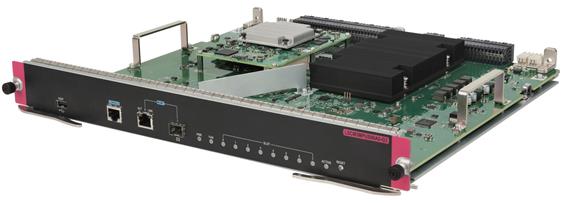
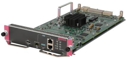
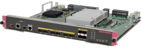
LSCM3MPUS10B0/LSCM3MPUS10C0
View
Figure2-23 MPU view (LSCM3MPUS10B0 as an example)
Technical specifications
Table2-33 Technical specifications
|
Item |
LSCM3MPUS10B0 |
LSCM3MPUS10C0 |
|
Net weight |
3.40 kg (7.50 lb) |
3.90 kg (8.60 lb) |
|
Dimensions (H × W × D) |
45 × 399 × 355 mm (1.77 × 15.71 × 13.98 in) |
|
|
Power consumption |
· Minimum: 71 W · Typical: 80 W · Maximum: 99 W |
· Minimum: 116 W · Typical: 126 W · Maximum: 173 W |
|
SDRAM |
4 GB |
|
|
Flash |
2 GB |
|
|
NVRAM |
1 MB |
|
|
Connector type |
· RJ-45 · LC · USB (Type A) |
|
|
Ports |
· 1 × console port · 1 × USB console port · 2 × network management ports (one RJ-45 port and one SFP port) · 1 × primary USB port |
|
|
Port transmission speed |
· Console port: 9600 bps (default) to 115200 bps · USB console port: ≤ 115200 bps (default: 9600 bps) · RJ-45 management port: 10/100/1000 Mbps, half/full duplex · SFP management port: 1000 Mbps |
|
|
Hot swapping |
Supported |
|
|
Applicable switch models |
S7510X-G, S7510X-G-PoE |
|
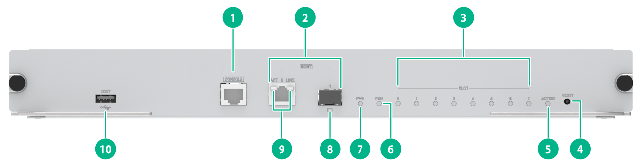
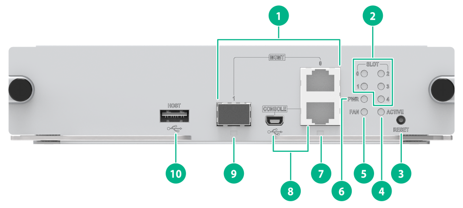
Ports and LEDs
Figure2-24 Front panel
|
(1) Console ports |
(2) Network management ports |
|
(3) Card status LEDs (SLOT) |
(4) Reset button (RESET) |
|
(5) MPU active/standby status LED (ACTIVE) |
(6) Fan tray status LED (FAN) |
|
(7) Power module status LED (PWR) |
(8) SFP fiber management Ethernet port LED (LINK/ACT) |
|
(9) 10/100/1000BASE-T copper management Ethernet port LEDs (LINK and ACT) |
(10) USB port |
Table2-34 LED description
|
LED |
Status |
Description |
|
10/100/1000BASE-T copper management Ethernet port LEDs |
LINK: Steady on ACT: Flashing |
A link is present, and the port is receiving or sending data. |
|
LINK: Steady on ACT: Off |
A link is present. |
|
|
LINK: Off ACT: Off |
No link is present. |
|
|
SFP fiber management Ethernet port LED |
Flashing |
A link is present, and the port is receiving or sending data. |
|
Steady on |
A link is present. |
|
|
Off |
No link is present. |
|
|
Power module status LED |
Steady green |
All power modules are operating correctly. |
|
Steady red |
A power module is not outputting power because one of the following conditions exists: · The power module is faulty or switched off. · The power cord is disconnected. · The external power supply system has a power outage. |
|
|
Off |
· No power modules are installed in the chassis. · No power modules are outputting power because one of the following conditions exists: ¡ The power modules are faulty or switched off. ¡ The power cords are disconnected. ¡ The external power supply system has a power outage. |
|
|
Fan tray status LED |
Steady green |
The fan tray is operating correctly. |
|
Steady red |
A fan problem has occurred or the fan tray is not in position. |
|
|
Off |
The switch is not powered on. |
|
|
Card status LED |
Flashing green |
The card is operating correctly. |
|
Flashing green (four times per second) |
The card is loading software. If the LED keeps in this state, the software version running on the switch is not compatible with the card. |
|
|
Steady red |
The card is starting up or faulty. |
|
|
Flashing red |
The temperature of the card has exceeded the upper warning threshold or has dropped below the lower warning threshold. |
|
|
Off |
No card is present. |
|
|
MPU active/standby state LED |
On |
The MPU is in active state. |
|
Off |
· The MPU is in standby state. · The MPU is faulty. To further determine the MPU status, see the card status LED. |
|
|
NOTE: Before the active MPU starts up, all card LEDs are off. The table describes the card LED status after the active MPU starts up. |
Table2-35 Button description
|
Button mark |
Name |
Description |
|
RESET |
Reset button |
To reset the MPU, press the reset button. In a single MPU configuration, pressing the reset button on the MPU triggers not only a reset of the MPU but also a restart of the entire device. In a dual-MPU configuration, pressing the reset button on the active MPU triggers an active/standby MPU switchover. If you press the reset button on the standby MPU, only the standby MPU will be reset without causing the entire device to restart. |
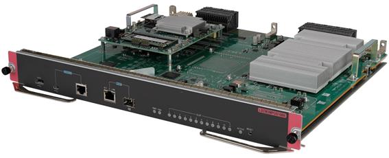
LSCM3MPUS10B0-G3
View
Figure2-25 MPU view
Technical specifications
Table2-36 Technical specifications
|
Item |
LSCM3MPUS10B0-G3 |
|
Net weight |
3.25 kg (7.16 lb) |
|
Dimensions (H × W × D) |
45 × 399 × 355 mm (1.77 × 15.71 × 13.98 in) |
|
Power consumption |
· Minimum: 70 W · Typical: 75 W · Maximum: 92 W |
|
SDRAM |
4 GB |
|
Flash |
8 GB |
|
NVRAM |
1 MB |
|
Connector type |
· RJ-45 · LC · USB (Type A) |
|
Ports |
· 1 × console port · 2 × network management ports (one RJ-45 port and one SFP port) · 1 × primary USB port |
|
Port transmission speed |
· Console port: 9600 bps (default) to 115200 bps · RJ-45 management port: 10/100/1000 Mbps, half/full duplex · SFP management port: 1000 Mbps |
|
Hot swapping |
Supported |
|
Applicable switch models |
S7510X-G, S7510X-G-PoE |
Ports and LEDs
Figure2-26 Front panel

|
(1) Console port |
(2) Network management ports |
|
(3) Card status LEDs (SLOT) |
(4) Reset button (RESET) |
|
(5) MPU active/standby status LED (ACTIVE) |
(6) Fan tray status LED (FAN) |
|
(7) Power module status LED (PWR) |
(8) SFP fiber management Ethernet port LED (LINK/ACT) |
|
(9) 10/100/1000BASE-T copper management Ethernet port LEDs (LINK and ACT) |
(10) USB port |
Table2-37 LED description
|
LED |
Status |
Description |
|
10/100/1000BASE-T copper management Ethernet port LEDs |
LINK: Steady on ACT: Flashing |
A link is present, and the port is receiving or sending data. |
|
LINK: Steady on ACT: Off |
A link is present. |
|
|
LINK: Off ACT: Off |
No link is present. |
|
|
SFP fiber management Ethernet port LED |
Flashing |
A link is present, and the port is receiving or sending data. |
|
Steady on |
A link is present. |
|
|
Off |
No link is present. |
|
|
Power module status LED |
Steady green |
All power modules are operating correctly. |
|
Steady red |
A power module is not outputting power because one of the following conditions exists: · The power module is faulty or switched off. · The power cord is disconnected. · The external power supply system has a power outage. |
|
|
Off |
· No power modules are installed in the chassis. · No power modules are outputting power because one of the following conditions exists: ¡ The power modules are faulty or switched off. ¡ The power cords are disconnected. ¡ The external power supply system has a power outage. |
|
|
Fan tray status LED |
Steady green |
The fan tray is operating correctly. |
|
Steady red |
A fan problem has occurred or the fan tray is not in position. |
|
|
Off |
The switch is not powered on. |
|
|
Card status LED |
Flashing green |
The card is operating correctly. |
|
Flashing green (four times per second) |
The card is loading software. If the LED keeps in this state, the software version running on the switch is not compatible with the card. |
|
|
Steady red |
The card is starting up or faulty. |
|
|
Flashing red |
The temperature of the card has exceeded the upper warning threshold or has dropped below the lower warning threshold. |
|
|
Off |
No card is present. |
|
|
MPU active/standby state LED |
On |
The MPU is in active state. |
|
Off |
· The MPU is in standby state. · The MPU is faulty. To further determine the MPU status, see the card status LED. |
|
|
NOTE: Before the active MPU starts up, all card LEDs are off. The table describes the card LED status after the active MPU starts up. |
Table2-38 Button description
|
Button mark |
Name |
Description |
|
RESET |
Reset button |
To reset the MPU, press the reset button. In a single MPU configuration, pressing the reset button on the MPU triggers not only a reset of the MPU but also a restart of the entire device. In a dual-MPU configuration, pressing the reset button on the active MPU triggers an active/standby MPU switchover. If you press the reset button on the standby MPU, only the standby MPU will be reset without causing the entire device to restart. |
Restrictions and guidelines for service modules
Do not install an LSCM1GT48SC0 interface module together with the following types of cards on the same switch:
· SC card prefixed with LSCM2.
· SD card.
· SF card.
Do not install a card prefixed with LSCM1 and a card prefixed with LSCM3 on the same switch.
For the S7503X-M-G switch, you can install an MPU or service module in slot 1.
100G interface modules
LSCM2CGS8QS8SF0/LSCM3CGS8QS8SF0/LSCM3CGS8QS8SF0-G3
View
Figure2-27 Interface module view (LSCM2CGS8QS8SF0 as an example)
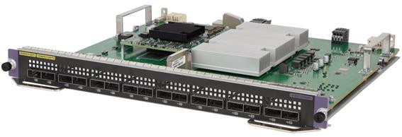
Technical specifications
Table2-39 Technical specifications
|
Item |
LSCM2CGS8QS8SF0 |
LSCM3CGS8QS8SF0 |
LSCM3CGS8QS8SF0-G3 |
|
Net weight |
3.35 kg (7.39 lb) |
3.30 kg (7.28 lb) |
|
|
Dimensions (H × W × D) |
40 × 399 × 355 mm (1.57 × 15.71 × 13.98 in) |
||
|
Power consumption |
· Minimum: 75 W · Typical: 97 W · Maximum: 175 W |
· Minimum: 75 W · Typical: 97 W · Maximum: 178 W |
· Minimum: 66 W · Typical: 88 W · Maximum: 170 W |
|
Port quantity |
16 |
||
|
Port type |
· 100GBASE-R-QSFP28 fiber port · 40GBASE-R-QSFP+ port |
||
|
Available transceiver modules and cables |
· QSFP+ transceiver modules · QSFP+ DAC cables · QSFP+ to SFP+ DAC cables · QSFP+ fiber cables · QSFP28 transceiver modules · QSFP28 fiber cables |
||
|
Services |
The card provides data access and forwarding with eight 100G Ethernet fiber ports and eight 40G Ethernet fiber ports |
||
|
Hot swapping |
Supported |
||
Ports and LEDs
Figure2-28 Front panel
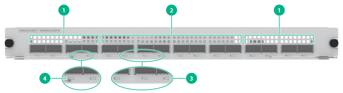
|
(1) 40GBASE-R-QSFP+ fiber ports |
(2) 100GBASE-R-QSFP28 fiber ports |
|
(3) 100GBASE-R-QSFP28 fiber port LED |
(4) 40GBASE-R-QSFP+ fiber port LED |
Table2-40 LED description
|
LED |
Status |
Description |
|
QSFP+ port LED |
Flashing |
The QSFP+ port is sending or receiving data. |
|
On |
A link is present on the QSFP+ port. |
|
|
Off |
No link is present on the QSFP+ port. |
|
|
QSFP28 port LED |
Flashing |
The QSFP28 port is sending or receiving data. |
|
On |
A link is present on the QSFP28 port. |
|
|
Off |
No link is present on the QSFP28 port. |
|
|
NOTE: You can check the QSFP28 port speed by observing the color of the QSFP28 port LED. Green indicates a speed of 100 Gbps, and yellow indicates a speed of less than 100 Gbps. |
40G interface modules
LSCM1QGS8CSSE0/LSCM3QGS8CSSE0
View
Figure2-29 Interface module view (LSCM1QGS8CSSE0 as an example)
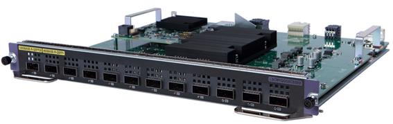
Technical specifications
Table2-41 Technical specifications
|
Item |
LSCM1QGS8CSSE0 |
LSCM3QGS8CSSE0 |
|
Net weight |
3.40 kg (7.50 lb) |
3.50 kg (7.72 lb) |
|
Dimensions (H × W × D) |
40 × 399 × 355 mm (1.57 × 15.71 × 13.98 in) |
|
|
Power consumption |
· Minimum: 66 W · Typical: 86 W · Maximum: 118 W |
· Minimum: 70 W · Typical: 90 W · Maximum: 124 W |
|
Port quantity |
12 |
|
|
Port type |
· 100GBASE-R-QSFP28 fiber port · 40GBASE-R-QSFP+ port |
|
|
Available transceiver modules and cables |
· QSFP+ transceiver modules · QSFP+ DAC cables · QSFP+ to SFP+ DAC cables · QSFP+ fiber cables · QSFP28 transceiver modules · QSFP28 fiber cables |
|
|
Services |
The card provides data access and forwarding with four 100G Ethernet fiber ports and eight 40G Ethernet fiber ports |
|
|
Hot swapping |
Supported |
|
Ports and LEDs
Figure2-30 Front panel
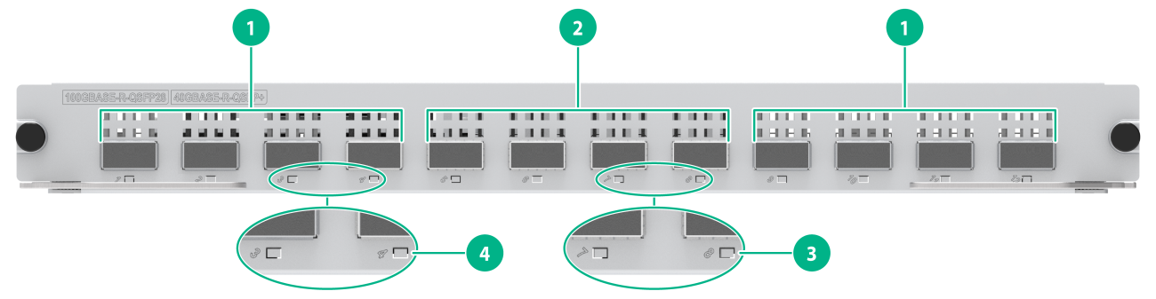
|
(1) 40GBASE-R-QSFP+ fiber ports |
(2) 100GBASE-R-QSFP28 fiber ports |
|
(3) 100GBASE-R-QSFP28 fiber port LED |
(4) 40GBASE-R-QSFP+ fiber port LED |
Table2-42 LED description
|
LED |
Status |
Description |
|
QSFP+ port LED |
Flashing |
The QSFP+ port is sending or receiving data. |
|
On |
A link is present on the QSFP+ port. |
|
|
Off |
No link is present on the QSFP+ port. |
|
|
QSFP28 port LED |
Flashing |
The QSFP28 port is sending or receiving data. |
|
On |
A link is present on the QSFP28 port. |
|
|
Off |
No link is present on the QSFP28 port. |
|
|
NOTE: You can check the QSFP28 port speed by observing the color of the QSFP28 port LED. Green indicates a speed of 100 Gbps, and yellow indicates a speed of less than 100 Gbps. |
25G interface modules
LSCM2YGS16TS8SF0
View
Figure2-31 Interface module view
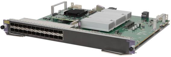
Technical specifications
Table2-43 Technical specifications
|
Item |
Specification |
|
Net weight |
3.35 kg (7.39 lb) |
|
Dimensions (H × W × D) |
40 × 399 × 355 mm (1.57 × 15.71 × 13.98 in) |
|
Power consumption |
· Minimum: 61 W · Typical: 69 W · Maximum: 115 W |
|
Port quantity |
24 |
|
Port type |
· 25GBASE-R-SFP28 fiber port · 10GBASE-R-SFP+ fiber port |
|
Available transceiver modules and cables |
· SFP28 transceiver modules · SFP28 DAC cables · SFP28 AOC cables · 10G SFP+ transceiver modules · 10G SFP+ DAC cables · 2.5G SFP transceiver modules · 1G SFP transceiver modules |
|
Services |
The card provides data access and forwarding with sixteen 25G Ethernet fiber ports and eight 10G Ethernet fiber ports |
|
Hot swapping |
Supported |
Ports and LEDs
Figure2-32 Front panel
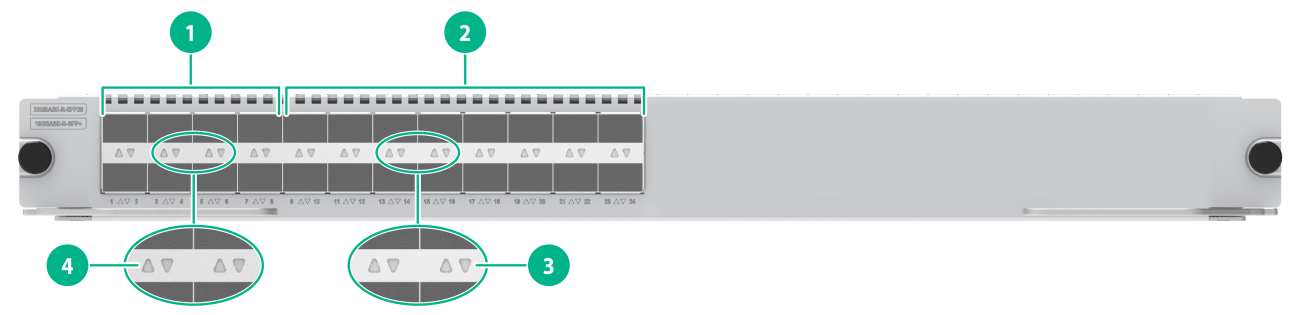
|
(1) 25GBASE-R-SFP28 fiber ports |
(2) 10GBASE-R-SFP+ fiber ports |
|
(3) 10GBASE-R-SFP+ fiber port LED |
(4) 25GBASE-R-SFP28 fiber port LED |
Table2-44 LED description
|
LED |
Status |
Description |
|
SFP+ port LED |
Flashing |
The SFP+ port is sending or receiving data. |
|
On |
A link is present on the SFP+ port. |
|
|
Off |
No link is present on the SFP+ port. |
|
|
SFP28 port LED |
Flashing |
The SFP28 port is sending or receiving data. |
|
On |
A link is present on the SFP28 port. |
|
|
Off |
No link is present on the SFP28 port. |
|
|
NOTE: You can check the SFP+ port speed by observing the color of the SFP+ port LED. Green indicates a speed of 10 Gbps, and yellow indicates a speed of 1000 Mbps. |
LSCM2YGS32TS16SF0
View
Figure2-33 Interface module view
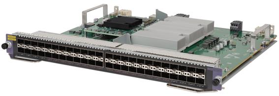
Technical specifications
Table2-45 Technical specifications
|
Item |
Specification |
|
Net weight |
3.55 kg (7.83 lb) |
|
Dimensions (H × W × D) |
40 × 399 × 355 mm (1.57 × 15.71 × 13.98 in) |
|
Power consumption |
· Minimum: 74 W · Typical: 87 W · Maximum: 168 W |
|
Port quantity |
48 |
|
Port type |
· 25GBASE-R-SFP28 fiber port · 10GBASE-R-SFP+ fiber port |
|
Available transceiver modules and cables |
· SFP28 transceiver modules · SFP28 DAC cables · SFP28 AOC cables · 10G SFP+ transceiver modules · 10G SFP+ DAC cables · 2.5G SFP transceiver modules · 1G SFP transceiver modules |
|
Services |
The card provides data access and forwarding with thirty-two 25G Ethernet fiber ports and sixteen 10G Ethernet fiber ports |
|
Hot swapping |
Supported |
Ports and LEDs
Figure2-34 Front panel
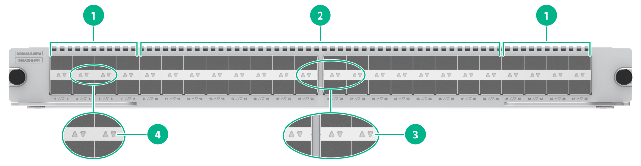
|
(1) 10GBASE-R-SFP+ fiber ports |
(2) 25GBASE-R-SFP28 fiber ports |
|
(3) 25GBASE-R-SFP28 fiber port LED |
(4) 10GBASE-R-SFP+ fiber port LED |
Table2-46 LED description
|
LED |
Status |
Description |
|
SFP+ port LED |
Flashing |
The SFP+ port is sending or receiving data. |
|
On |
A link is present on the SFP+ port. |
|
|
Off |
No link is present on the SFP+ port. |
|
|
SFP28 port LED |
Flashing |
The SFP28 port is sending or receiving data. |
|
On |
A link is present on the SFP28 port. |
|
|
Off |
No link is present on the SFP28 port. |
|
|
NOTE: You can check the SFP+ port speed by observing the color of the SFP+ port LED. Green indicates a speed of 10 Gbps, and yellow indicates a speed of 1000 Mbps. |
LSCM2YSV16TSV32SD0
When you install an LSCM2YSV16TSV32SD0 interface module, order a power module that can be used for setting up a PoE system. The requirements for setting up a PoE system vary by switch model. Make sure the maximum PoE power provided by the power module is greater than the PoE power consumption.
View
Figure2-35 Interface module view
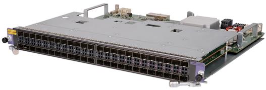
Technical specifications
Table2-47 Technical specifications
|
Item |
Specification |
|
Net weight |
4.15 kg (9.15 lb) |
|
Dimensions (H × W × D) |
40 × 399 × 355 mm (1.57 × 15.71 × 13.98 in) |
|
Power consumption (without PoE power supply) |
· Minimum: 59 W · Typical: 101 W · Maximum: 140 W |
|
Port quantity |
48 |
|
Port type |
· 25GBASE-R-SFP28-PoE++ fiber port · 10GBASE-R-SFP+-PoE++ fiber port |
|
Available transceiver modules and cables |
· SFP28 transceiver modules · SFP28 DAC cables · SFP28 AOC cables · 10G SFP+ transceiver modules · 10G SFP+ DAC cables · 1G SFP transceiver modules |
|
Maximum PoE power per port |
Each port provides a maximum power of 90 W for the connected device |
|
Maximum PoE power per card |
Each card provides a maximum power of 1900 W · Odd-numbered ports (upper row of ports on the panel) provide a maximum power of 950 W · Even-numbered ports (lower row of ports on the panel) provide a maximum power of 950 W |
|
Services |
The card provides data access and forwarding with sixteen 25G Ethernet fiber ports and thirty-two 10G Ethernet fiber ports |
|
Hot swapping |
Supported |
Ports and LEDs
Figure2-36 Front panel
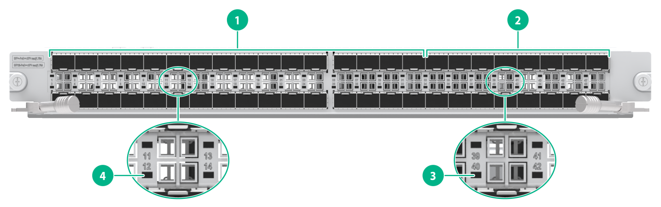
|
(1) 10GBASE-R-SFP+-PoE++ fiber ports |
(2) 25GBASE-R-SFP28-PoE++ fiber ports |
|
(3) 25GBASE-R-SFP28-PoE++ fiber port LED |
(4) 10GBASE-R-SFP+-PoE++ fiber port LED |
Table2-48 LED description
|
LED |
Status |
Description |
|
SFP+ port LED |
Flashing |
The SFP+ port is sending or receiving data. |
|
On |
A link is present on the SFP+ port. |
|
|
Off |
No link is present on the SFP+ port. |
|
|
SFP28 port LED |
Flashing |
The SFP28 port is sending or receiving data. |
|
On |
A link is present on the SFP28 port. |
|
|
Off |
No link is present on the SFP28 port. |
|
|
NOTE: You can check the SFP+ port speed by observing the color of the SFP+ port LED. Green indicates a speed of 10 Gbps, and yellow indicates a speed of 1000 Mbps. |
10G interface modules
LSCM1TGS48SE0/LSCM3TGS48SE0
View
Figure2-37 Interface module view (LSCM1TGS48SE0 as an example)
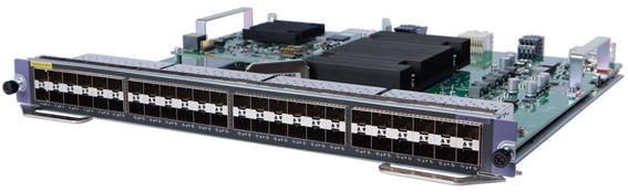
Technical specifications
Table2-49 Technical specifications
|
Item |
LSCM1TGS48SE0 |
LSCM3TGS48SE0 |
|
Net weight |
3.60 kg (7.94 lb) |
3.65 kg (8.05 lb) |
|
Dimensions (H × W × D) |
40 × 399 × 355 mm (1.57 × 15.71 × 13.98 in) |
|
|
Power consumption |
· Minimum: 60 W · Typical: 85 W · Maximum: 115 W |
· Minimum: 64 W · Typical: 89 W · Maximum: 121 W |
|
Port quantity |
48 |
|
|
Port type |
10GBASE-R-SFP+ fiber port |
|
|
Available transceiver modules and cables |
· 10G SFP+ transceiver modules · 10G SFP+ DAC cables · 2.5G SFP transceiver modules · 1G SFP transceiver modules |
|
|
Services |
The card provides data access and forwarding with forty-eight 10GBASE-R-SFP+ fiber ports |
|
|
Hot swapping |
Supported |
|
Ports and LEDs
Figure2-38 Front panel
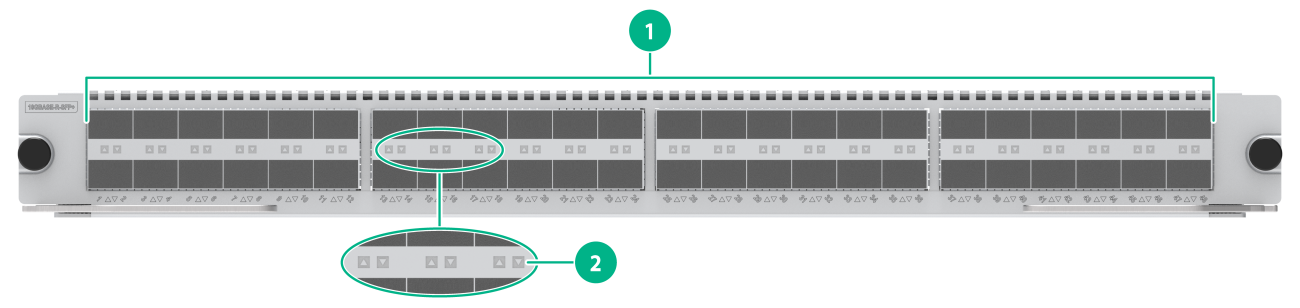
|
(1) 10GBASE-R-SFP+ fiber ports |
(2) 10GBASE-R-SFP+ fiber port LED |
Table2-50 LED description
|
LED |
Status |
Description |
|
SFP+ port LED |
Flashing |
The SFP+ port is sending or receiving data. |
|
On |
A link is present on the SFP+ port. |
|
|
Off |
No link is present on the SFP+ port. |
|
|
NOTE: You can check the SFP+ port speed by observing the color of the SFP+ port LED. Green indicates a speed of 10 Gbps, and yellow indicates a speed of 1000 Mbps. |
LSCM2TGS16SD0-G3
View
Figure2-39 Interface module view
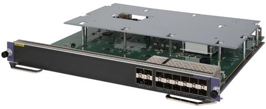
Technical specifications
Table2-51 Technical specifications
|
Item |
Specification |
|
Net weight |
3.25 kg (7.16 lb) |
|
Dimensions (H × W × D) |
40 × 399 × 355 mm (1.57 × 15.71 × 13.98 in) |
|
Power consumption |
· Minimum: 18 W · Typical: 26 W · Maximum: 40 W |
|
Port quantity |
16 |
|
Port type |
10GBASE-R-SFP+ fiber port |
|
Available transceiver modules and cables |
· 10G SFP+ transceiver modules · 10G SFP+ DAC cables · 2.5G SFP transceiver modules · 1G SFP transceiver modules |
|
Services |
The card provides data access and forwarding with sixteen 10GBASE-R-SFP+ fiber ports. |
|
Hot swapping |
Supported |
Ports and LEDs
Figure2-40 Front panel
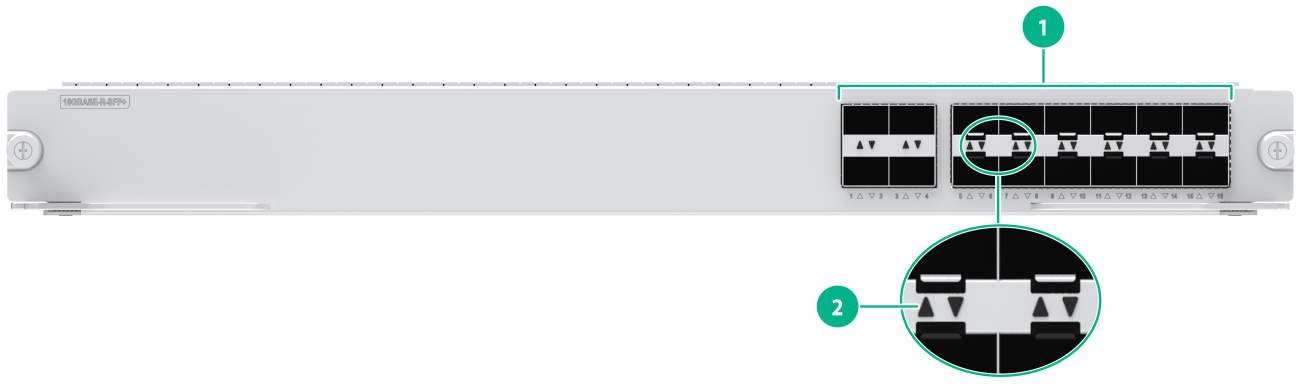
|
(1) 1000BASE-X-SFP+ fiber ports |
(2) 10GBASE-R-SFP+ fiber port LED |
Table2-52 LED description
|
LED |
Status |
Description |
|
SFP+ port LED |
Flashing |
The SFP+ port is sending or receiving data. |
|
On |
A link is present on the SFP+ port. |
|
|
Off |
No link is present on the SFP+ port. |
|
|
NOTE: You can check the SFP+ port speed by observing the color of the SFP+ port LED. Green indicates a speed of 10 Gbps, and yellow indicates a speed of 1000 Mbps. |
LSCM2TGS16GPSC0/LSCM2TGS16GPSD0
View
Figure2-41 Interface module view (LSCM2TGS16GPSC0 as an example)
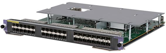
Technical specifications
Table2-53 Technical specifications
|
Item |
LSCM2TGS16GPSC0 |
LSCM2TGS16GPSD0 |
|
Net weight |
3.50 kg (7.72 lb) |
3.45 kg (7.61 lb) |
|
Dimensions (H × W × D) |
40 × 399 × 355 mm (1.57 × 15.71 × 13.98 in) |
|
|
Power consumption |
· Minimum: 26 W · Typical: 37 W · Maximum: 58 W |
|
|
Port quantity |
40 |
|
|
Port type |
· 10GBASE-R-SFP+ fiber port · 1000BASE-X-SFP fiber port |
|
|
Available transceiver modules and cables |
· 10G SFP+ transceiver modules · 10G SFP+ DAC cables · 2.5G SFP transceiver modules · 100M/1G SFP transceiver modules |
|
|
Services |
The card provides data access and forwarding with sixteen 10GBASE-R-SFP+ fiber ports and twenty-four 1000BASE-X-SFP fiber ports |
|
|
Hot swapping |
Supported |
|
Ports and LEDs
Figure2-42 Front panel
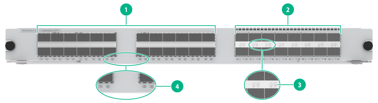
|
(1) 1000BASE-X-SFP fiber ports |
(2) 10GBASE-R-SFP+ fiber ports |
|
(3) 10GBASE-R-SFP+ fiber port LED |
(4) 1000BASE-X-SFP fiber port LED |
Table2-54 LED description
|
LED |
Status |
Description |
|
SFP+ port LED |
Flashing |
The SFP+ port is sending or receiving data. |
|
On |
A link is present on the SFP+ port. |
|
|
Off |
No link is present on the SFP+ port. |
|
|
SFP port LED |
Flashing |
The SFP port is sending or receiving data. |
|
On |
A link is present on the SFP port. |
|
|
Off |
No link is present on the SFP port. |
|
|
NOTE: You can check the SFP+ port speed by observing the color of the SFP+ port LED. Green indicates a speed of 10 Gbps, and yellow indicates a speed of 1000 Mbps. |
LSCM2TGS16GP32SD0/LSCM2TGS16GP32SD0-G3
View
Figure2-43 Interface module view

Technical specifications
Table2-55 Technical specifications
|
Item |
LSCM2TGS16GP32SD0 |
LSCM2TGS16GP32SD0-G3 |
|
Net weight |
3.45 kg (7.61 lb) |
3.60 kg (7.94 lb) |
|
Dimensions (H × W × D) |
40 × 399 × 355 mm (1.57 × 15.71 × 13.98 in) |
|
|
Power consumption |
· Minimum: 31 W · Typical: 41 W · Maximum: 69 W |
· Maximum: 22 W · Maximum: 40 W · Maximum: 63 W |
|
Port quantity |
48 |
|
|
Port type |
· 10GBASE-R-SFP+ fiber port · 1000BASE-X-SFP fiber port |
|
|
Available transceiver modules and cables |
· 10G SFP+ transceiver modules · 10G SFP+ DAC cables · 2.5G SFP transceiver modules · 100M/1G SFP transceiver modules |
|
|
Services |
The card provides data access and forwarding with sixteen 10GBASE-R-SFP+ fiber ports and thirty-two 1000BASE-X-SFP fiber ports |
|
|
Hot swapping |
Supported |
|
Ports and LEDs
Figure2-44 Front panel
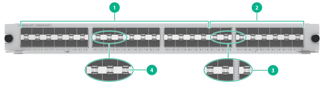
|
(1) 1000BASE-X-SFP fiber ports |
(2) 10GBASE-R-SFP+ fiber ports |
|
(3) 10GBASE-R-SFP+ fiber port LED |
(4) 1000BASE-X-SFP fiber port LED |
Table2-56 LED description
|
LED |
Status |
Description |
|
SFP+ port LED |
Flashing |
The SFP+ port is sending or receiving data. |
|
On |
A link is present on the SFP+ port. |
|
|
Off |
No link is present on the SFP+ port. |
|
|
SFP port LED |
Flashing |
The SFP port is sending or receiving data. |
|
On |
A link is present on the SFP port. |
|
|
Off |
No link is present on the SFP port. |
|
|
NOTE: You can check the SFP+ port speed by observing the color of the SFP+ port LED. Green indicates a speed of 10 Gbps, and yellow indicates a speed of 1000 Mbps. |
LSCM2TGS48SF0/LSCM3TGS48SF0
View
Figure2-45 Interface module view (LSCM2TGS48SF0 as an example)
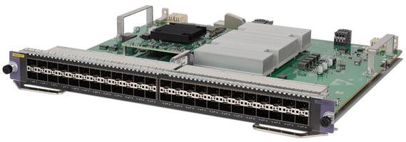
Technical specifications
Table2-57 Technical specifications
|
Item |
LSCM2TGS48SF0 |
LSCM3TGS48SF0 |
|
Net weight |
3.60 kg (7.94 lb) |
|
|
Dimensions (H × W × D) |
40 × 399 × 355 mm (1.57 × 15.71 × 13.98 in) |
|
|
Power consumption |
· Minimum: 73 W · Typical: 81 W · Maximum: 149 W |
· Minimum: 73 W · Typical: 81 W · Maximum: 152 W |
|
Port quantity |
48 |
|
|
Port type |
10GBASE-R-SFP+ fiber port |
|
|
Available transceiver modules and cables |
· 10G SFP+ transceiver modules · 10G SFP+ DAC cables · 2.5G SFP transceiver modules · 1G SFP transceiver modules |
|
|
Services |
The card provides data access and forwarding with forty-eight 10GBASE-R-SFP+ fiber ports |
|
|
Hot swapping |
Supported |
|
Ports and LEDs
Figure2-46 Front panel
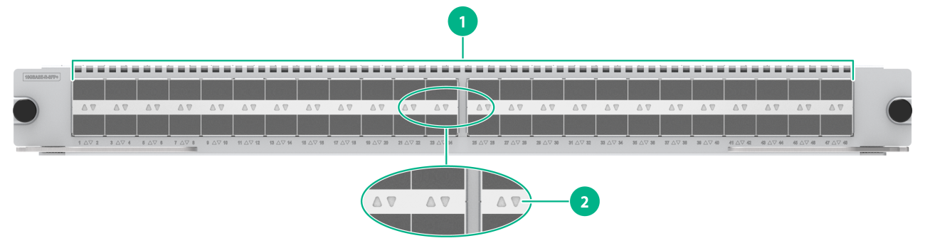
|
(1) 10GBASE-R-SFP+ fiber ports |
(2) 10GBASE-R-SFP+ fiber port LED |
Table2-58 LED description
|
LED |
Status |
Description |
|
SFP+ port LED |
Flashing |
The SFP+ port is sending or receiving data. |
|
On |
A link is present on the SFP+ port. |
|
|
Off |
No link is present on the SFP+ port. |
|
|
NOTE: You can check the SFP+ port speed by observing the color of the SFP+ port LED. Green indicates a speed of 10 Gbps, and yellow indicates a speed of 1000 Mbps. |
LSCM3TGS48SF0-G3
View
Figure2-47 Interface module view
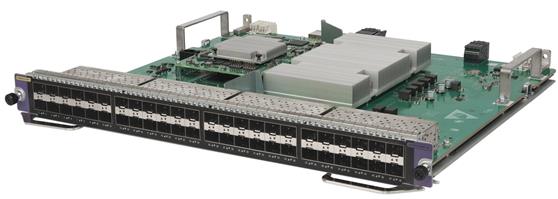
Technical specifications
Table2-59 Technical specifications
|
Item |
Specification |
|
Net weight |
3.55 kg (7.83 lb) |
|
Dimensions (H × W × D) |
40 × 399 × 355 mm (1.57 × 15.71 × 13.98 in) |
|
Power consumption |
· Minimum: 59 W · Typical: 72 W · Maximum: 144 W |
|
Port quantity |
48 |
|
Port type |
10GBASE-R-SFP+ fiber port |
|
Available transceiver modules and cables |
· 10G SFP+ transceiver modules · 10G SFP+ DAC cables · 2.5G SFP transceiver modules · 1G SFP transceiver modules |
|
Services |
The card provides data access and forwarding with forty-eight 10GBASE-R-SFP+ fiber ports |
|
Hot swapping |
Supported |
Ports and LEDs
Figure2-48 Front panel
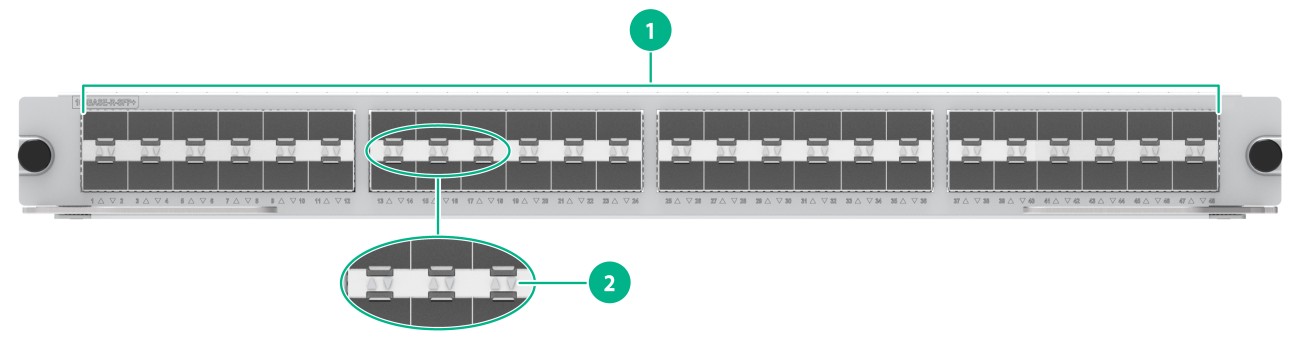
|
(1) 10GBASE-R-SFP+ fiber ports |
(2) 10GBASE-R-SFP+ fiber port LED |
Table2-60 LED description
|
LED |
Status |
Description |
|
SFP+ port LED |
Flashing |
The SFP+ port is sending or receiving data. |
|
On |
A link is present on the SFP+ port. |
|
|
Off |
No link is present on the SFP+ port. |
|
|
NOTE: You can check the SFP+ port speed by observing the color of the SFP+ port LED. Green indicates a speed of 10 Gbps, and yellow indicates a speed of 1000 Mbps. |
LSCM3TGS32GP16SF0
View
Figure2-49 Interface module view
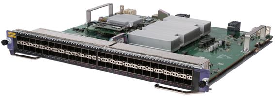
Technical specifications
Table2-61 Technical specifications
|
Item |
Specification |
|
Net weight |
3.50 kg (7.72 lb) |
|
Dimensions (H × W × D) |
40 × 399 × 355 mm (1.57 × 15.71 × 13.98 in) |
|
Power consumption |
· Minimum: 73 W · Typical: 80 W · Maximum: 146 W |
|
Port quantity |
48 |
|
Port type |
· 10GBASE-R-SFP+ fiber port · 1000BASE-X-SFP fiber port |
|
Available transceiver modules and cables |
· 10G SFP+ transceiver modules · 10G SFP+ DAC cables · 2.5G SFP transceiver modules · 100M/1G SFP transceiver modules |
|
Services |
The card provides data access and forwarding with thirty-two 10GBASE-R-SFP+ fiber ports and sixteen 1000BASE-X-SFP fiber ports |
|
Hot swapping |
Supported |
Ports and LEDs
Figure2-50 Front panel
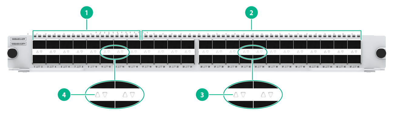
|
(1) 1000BASE-X-SFP fiber ports |
(2) 10GBASE-R-SFP+ fiber ports |
|
(3) 10GBASE-R-SFP+ fiber port LED |
(4) 1000BASE-X-SFP fiber port LED |
Table2-62 LED description
|
LED |
Status |
Description |
|
SFP+ port LED |
Flashing |
The SFP+ port is sending or receiving data. |
|
On |
A link is present on the SFP+ port. |
|
|
Off |
No link is present on the SFP+ port. |
|
|
SFP port LED |
Flashing |
The SFP port is sending or receiving data. |
|
On |
A link is present on the SFP port. |
|
|
Off |
No link is present on the SFP port. |
|
|
NOTE: You can check the SFP+ port speed by observing the color of the SFP+ port LED. Green indicates a speed of 10 Gbps, and yellow indicates a speed of 1000 Mbps. |
1G interface modules
LSCM1GT48SC0
View
Figure2-51 Interface module view
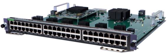
Technical specifications
Table2-63 Technical specifications
|
Item |
Specification |
|
Net weight |
2.90 kg (6.39 lb) |
|
Dimensions (H × W × D) |
40 × 399 × 355 mm (1.57 × 15.71 × 13.98 in) |
|
Power consumption |
· Minimum: 44 W · Typical: 45 W · Maximum: 48 W |
|
Port quantity |
48 |
|
Port type |
10/100/1000BASE-T port |
|
Available transceiver modules and cables |
Category 5 twisted pair cables |
|
Services |
The card provides data access and forwarding with forty-eight 10/100/1000BASE-T ports |
|
Hot swapping |
Supported |
Ports and LEDs
Figure2-52 Front panel
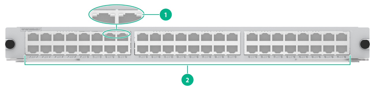
|
(1) 10/100/1000BASE-T port LED |
(2) 10/100/1000BASE-T ports |
Table2-64 LED description
|
LED |
Status |
Description |
|
RJ-45 Ethernet port LED |
Flashing |
The RJ-45 Ethernet port is receiving or sending data. |
|
On |
A link is present on the RJ-45 Ethernet port. |
|
|
Off |
No link is present on the RJ-45 Ethernet port. |
LSCM2GT48SC0/LSCM2GT48SD0/LSCM2GT48SD0-G3
View
Figure2-53 Interface module view (LSCM2GT48SC0 as an example)
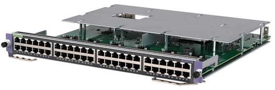
Technical specifications
Table2-65 Technical specifications
|
Item |
LSCM2GT48SC0 |
LSCM2GT48SD0 |
LSCM2GT48SD0-G3 |
|
Net weight |
3.65 kg (8.05 lb) |
3.60 kg (7.94 lb) |
3.55 kg (7.83 lb) |
|
Dimensions (H × W × D) |
40 × 399 × 355 mm (1.57 × 15.71 × 13.98 in) |
||
|
Power consumption |
· Minimum: 24 W · Typical: 33 W · Maximum: 44 W |
· Minimum: 24 W · Typical: 35 W · Maximum: 48 W |
|
|
Port quantity |
48 |
||
|
Port type |
10/100/1000BASE-T port |
||
|
Available transceiver modules and cables |
Category 5 twisted pair cables |
||
|
Services |
The card provides data access and forwarding with forty-eight 10/100/1000BASE-T ports |
||
|
Hot swapping |
Supported |
||
Ports and LEDs
Figure2-54 Front panel
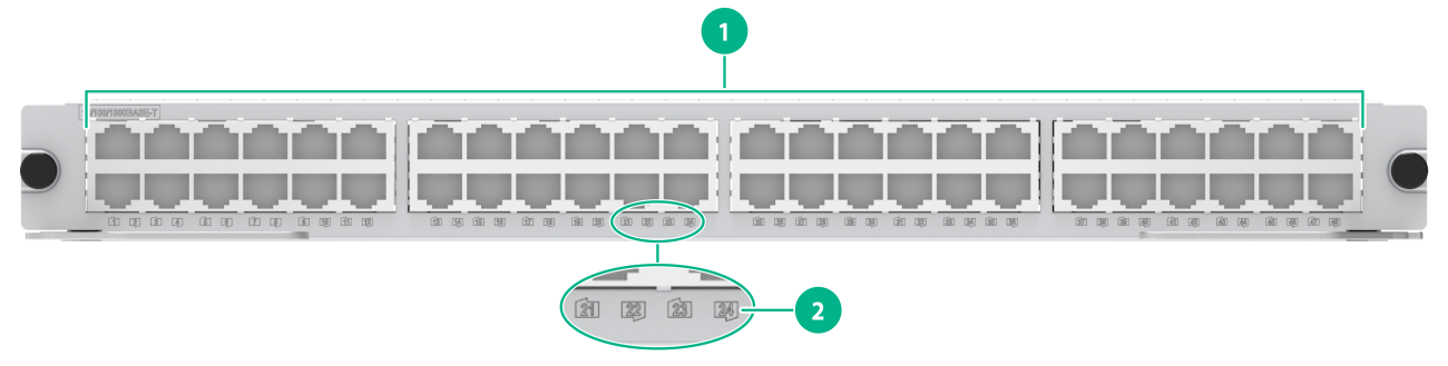
|
(1) 10/100/1000BASE-T ports |
(2) 10/100/1000BASE-T port LED |
Table2-66 LED description
|
LED |
Status |
Description |
|
RJ-45 Ethernet port LED |
Flashing |
The RJ-45 Ethernet port is receiving or sending data. |
|
On |
A link is present on the RJ-45 Ethernet port. |
|
|
Off |
No link is present on the RJ-45 Ethernet port. |
LSCM2GP24GTSC0/LSCM2GP24GTSD0
View
Figure2-55 Interface module view (LSCM2GP24GTSC0 as an example)
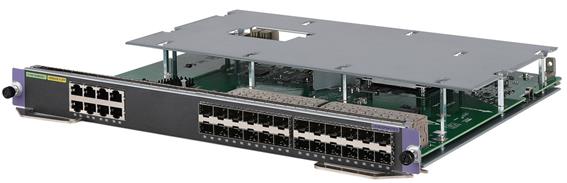
Technical specifications
Table2-67 Technical specifications
|
Item |
LSCM2GP24GTSC0 |
LSCM2GP24GTSD0 |
|
Net weight |
3.40 kg (7.50 lb) |
|
|
Dimensions (H × W × D) |
40 × 399 × 355 mm (1.57 × 15.71 × 13.98 in) |
|
|
Power consumption |
· Minimum: 24 W · Typical: 31 W · Maximum: 40 W |
|
|
Port quantity |
32 |
|
|
Port type |
· 1000BASE-X-SFP fiber port · 10/100/1000BASE-T port |
|
|
Available transceiver modules and cables |
· 2.5G SFP transceiver modules · 100M/1G SFP transceiver modules · Category 5 twisted pair cables |
|
|
Services |
The card provides data access and forwarding with twenty-four 1000BASE-X-SFP fiber ports and eight 10/100/1000BASE-T ports |
|
|
Hot swapping |
Supported |
|
Ports and LEDs
Figure2-56 Front panel
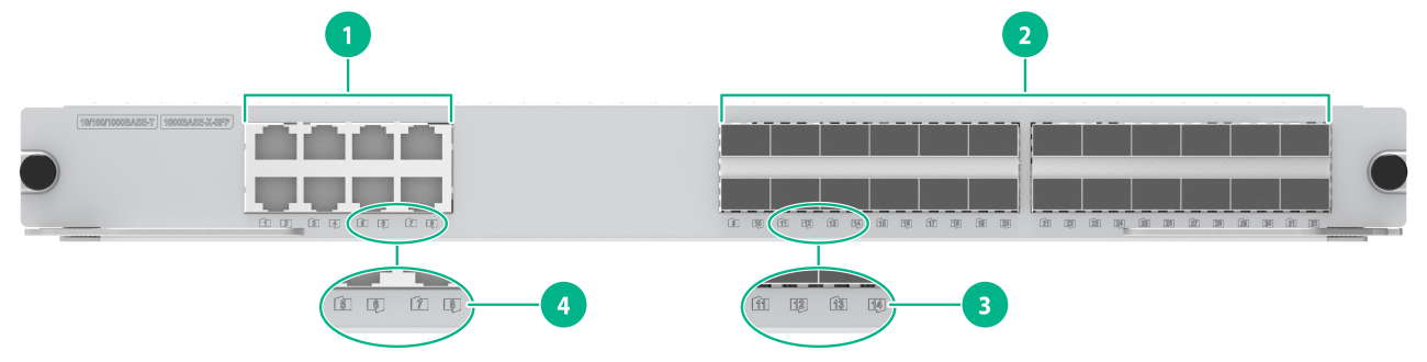
|
(1) 10/100/1000BASE-T ports |
(2) 1000BASE-X-SFP fiber ports |
|
(4) 1000BASE-X-SFP fiber port LED |
(3) 10/100/1000BASE-T port LED |
Table2-68 LED description
|
LED |
Status |
Description |
|
SFP port LED |
Flashing |
The SFP port is receiving or sending data. |
|
On |
A link is present on the SFP port. |
|
|
Off |
No link is present on the SFP port. |
|
|
RJ-45 Ethernet port LED |
Flashing |
The RJ-45 Ethernet port is receiving or sending data. |
|
On |
A link is present on the RJ-45 Ethernet port. |
|
|
Off |
No link is present on the RJ-45 Ethernet port. |
LSCM2GP48SC0/LSCM2GP48SD0/LSCM2GP48SD0-G3
View
Figure2-57 Interface module view (LSCM2GP48SC0 as an example)
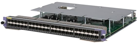
Technical specifications
Table2-69 Technical specifications
|
Item |
LSCM2GP48SC0 |
LSCM2GP48SD0 |
LSCM2GP48SD0-G3 |
|
Net weight |
3.50 kg (7.72 lb) |
3.55 kg (7.83 lb) |
|
|
Dimensions (H × W × D) |
40 × 399 × 355 mm (1.57 × 15.71 × 13.98 in) |
||
|
Power consumption |
· Minimum: 26 W · Typical: 37 W · Maximum: 52 W |
· Minimum: 21 W · Typical: 41 W · Maximum: 52 W |
|
|
Port quantity |
48 |
||
|
Port type |
1000BASE-X-SFP fiber port |
||
|
Available transceiver modules and cables |
· 2.5G SFP transceiver modules · 100M/1G SFP transceiver modules |
||
|
Services |
The card provides data access and forwarding with forty-eight 1000BASE-X-SFP fiber ports |
||
|
Hot swapping |
Supported |
||
Ports and LEDs
Figure2-58 Front panel
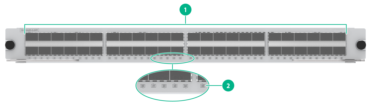
|
(1) 1000BASE-X-SFP fiber ports |
(2) 1000BASE-X-SFP fiber port LED |
Table2-70 LED description
|
LED |
Status |
Description |
|
SFP port LED |
Flashing |
The SFP port is receiving or sending data. |
|
On |
A link is present on the SFP port. |
|
|
Off |
No link is present on the SFP port. |
LSCM2GP40TS8SD0
View
Figure2-59 Interface module view
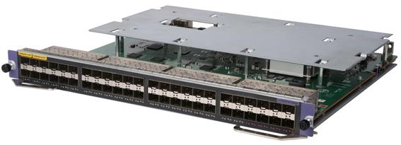
Technical specifications
Table2-71 Technical specifications
|
Item |
Specification |
|
Net weight |
3.50 kg (7.72 lb) |
|
Dimensions (H × W × D) |
40 × 399 × 355 mm (1.57 × 15.71 × 13.98 in) |
|
Power consumption |
· Minimum: 31 W · Typical: 41 W · Maximum: 66 W |
|
Port quantity |
48 |
|
Port type |
· 10GBASE-R-SFP+ fiber port · 1000BASE-X-SFP fiber port |
|
Available transceiver modules and cables |
· 10G SFP+ transceiver modules · 10G SFP+ DAC cables · 2.5G SFP transceiver modules · 100M/1G SFP transceiver modules |
|
Services |
The card provides data access and forwarding with eight 10GBASE-R-SFP+ fiber ports and forty 1000BASE-X-SFP fiber ports |
|
Hot swapping |
Supported |
Ports and LEDs
Figure2-60 Front panel
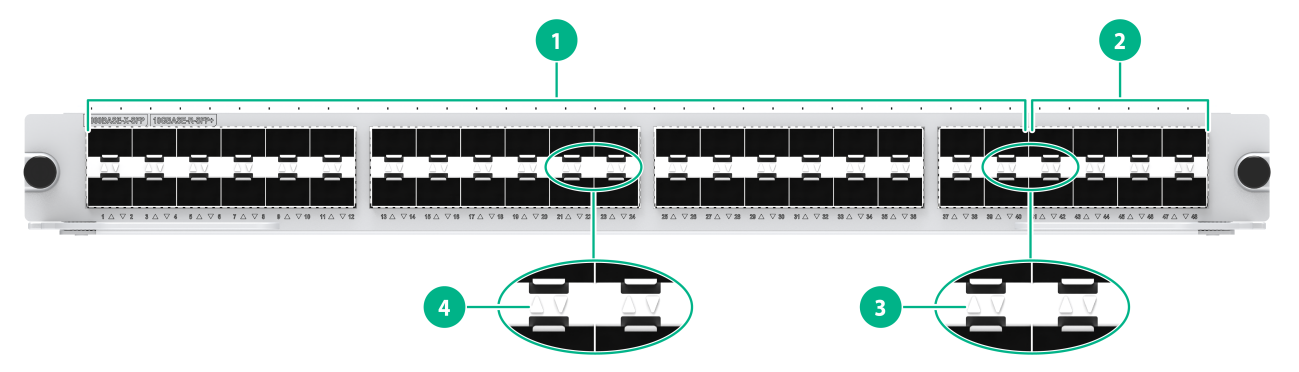
|
(1) 1000BASE-X-SFP fiber ports |
(2) 10GBASE-R-SFP+ fiber ports |
|
(3) 10GBASE-R-SFP+ fiber port LED |
(4) 1000BASE-X-SFP fiber port LED |
Table2-72 LED description
|
LED |
Status |
Description |
|
SFP+ port LED |
Flashing |
The SFP+ port is receiving or sending data. |
|
On |
A link is present on the SFP+ port. |
|
|
Off |
No link is present on the SFP+ port. |
|
|
SFP port LED |
Flashing |
The SFP port is receiving or sending data. |
|
On |
A link is present on the SFP port. |
|
|
Off |
No link is present on the SFP port. |
|
|
NOTE: You can check the SFP+ port speed by observing the color of the SFP+ port LED. Green indicates a speed of 10 Gbps, and yellow indicates a speed of 1000 Mbps. |
LSCM2GT24GPSC0/LSCM2GT24GPSD0
View
Figure2-61 Interface module view (LSCM2GT24GPSC0 as an example)
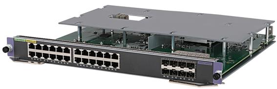
Technical specifications
Table2-73 Technical specifications
|
Item |
LSCM2GT24GPSC0 |
LSCM2GT24GPSD0 |
|
Net weight |
3.45 kg (7.61 lb) |
|
|
Dimensions (H × W × D) |
40 × 399 × 355 mm (1.57 × 15.71 × 13.98 in) |
|
|
Power consumption |
· Minimum: 22 W · Typical: 27 W · Maximum: 36 W |
|
|
Port quantity |
32 |
|
|
Port type |
· 1000BASE-X-SFP fiber port · 10/100/1000BASE-T port |
|
|
Available transceiver modules and cables |
· 2.5G SFP transceiver modules · 100M/1G SFP transceiver modules · Category 5 twisted pair cables |
|
|
Services |
The card provides data access and forwarding with eight 1000BASE-X-SFP fiber ports and twenty-four 10/100/1000BASE-T ports |
|
|
Hot swapping |
Supported |
|
Ports and LEDs
Figure2-62 Front panel
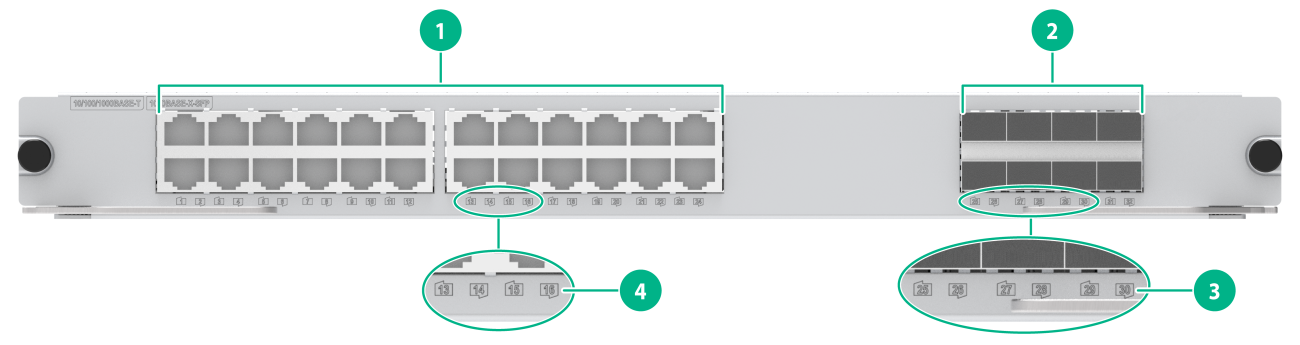
|
(1) 10/100/1000BASE-T ports |
(2) 1000BASE-X-SFP fiber ports |
|
(3) 1000BASE-X-SFP fiber port LED |
(4) 10/100/1000BASE-T port LED |
Table2-74 LED description
|
LED |
Status |
Description |
|
SFP port LED |
Flashing |
The SFP port is receiving or sending data. |
|
On |
A link is present on the SFP port. |
|
|
Off |
No link is present on the SFP port. |
|
|
RJ-45 Ethernet port LED |
Flashing |
The RJ-45 Ethernet port is receiving or sending data. |
|
On |
A link is present on the RJ-45 Ethernet port. |
|
|
Off |
No link is present on the RJ-45 Ethernet port. |
LSCM2GT24GPTSSC0/LSCM2GT24GPTSSD0
View
Figure2-63 Interface module view (LSCM2GT24GPTSSC0 as an example)
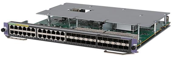
Technical specifications
Table2-75 Technical specifications
|
Item |
LSCM2GT24GPTSSC0 |
LSCM2GT24GPTSSD0 |
|
Net weight |
3.45 kg (7.61 lb) |
3.55 kg (7.83 lb) |
|
Dimensions (H × W × D) |
40 × 399 × 355 mm (1.57 × 15.71 × 13.98 in) |
|
|
Power consumption |
· Minimum: 25 W · Typical: 34 W · Maximum: 49 W |
|
|
Port quantity |
48 |
|
|
Port type |
· 10GBASE-R-SFP+ fiber port · 1000BASE-X-SFP fiber port · 10/100/1000BASE-T port |
|
|
Available transceiver modules and cables |
· 10G SFP+ transceiver modules · 10G SFP+ DAC cables · 2.5G SFP transceiver modules · 100M/1G SFP transceiver modules · Category 5 twisted pair cables |
|
|
Services |
The card provides data access and forwarding with four 10GBASE-R-SFP+ fiber ports, twenty 1000BASE-X-SFP fiber ports, and twenty-four 10/100/1000BASE-T ports |
|
|
Hot swapping |
Supported |
|
Ports and LEDs
Figure2-64 Front panel
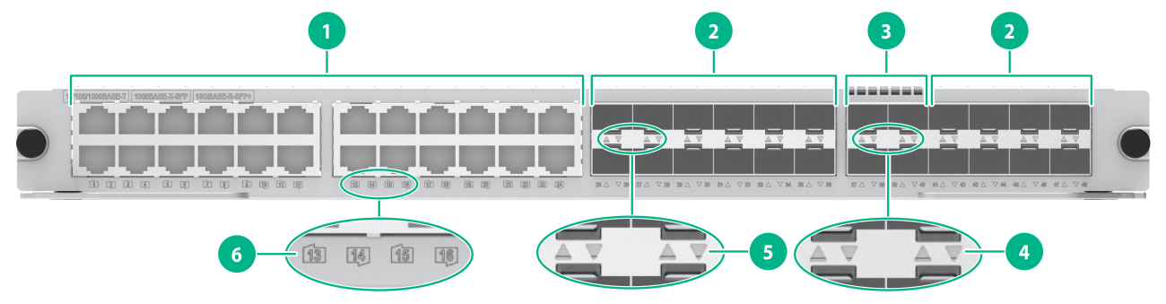
|
(1) 10/100/1000BASE-T ports |
(2) 1000BASE-X-SFP fiber ports |
|
(3) 10GBASE-R-SFP+ fiber ports |
(4) 10GBASE-R-SFP+ fiber port LED |
|
(5) 1000BASE-X-SFP fiber port LED |
(6) 10/100/1000BASE-T port LED |
Table2-76 LED description
|
LED |
Status |
Description |
|
SFP+ port LED |
Flashing |
The SFP+ port is receiving or sending data. |
|
On |
A link is present on the SFP+ port. |
|
|
Off |
No link is present on the SFP+ port. |
|
|
SFP port LED |
Flashing |
The SFP port is receiving or sending data. |
|
On |
A link is present on the SFP port. |
|
|
Off |
No link is present on the SFP port. |
|
|
RJ-45 Ethernet port LED |
Flashing |
The RJ-45 Ethernet port is receiving or sending data. |
|
On |
A link is present on the RJ-45 Ethernet port. |
|
|
Off |
No link is present on the RJ-45 Ethernet port. |
|
|
NOTE: You can check the SFP+ port speed by observing the color of the SFP+ port LED. Green indicates a speed of 10 Gbps, and yellow indicates a speed of 1000 Mbps. |
LSCM2GT24TSSD0
View
Figure2-65 Interface module view
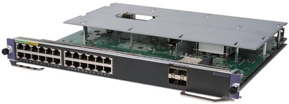
Technical specifications
Table2-77 Technical specifications
|
Item |
Specification |
|
Net weight |
3.40 kg (7.50 lb) |
|
Dimensions (H × W × D) |
40 × 399 × 355 mm (1.57 × 15.71 × 13.98 in) |
|
Power consumption |
· Minimum: 25 W · Typical: 30 W · Maximum: 40 W |
|
Port quantity |
28 |
|
Port type |
· 10GBASE-R-SFP+ fiber port · 10/100/1000BASE-T port |
|
Available transceiver modules and cables |
· 10G SFP+ transceiver modules · 10G SFP+ DAC cables · Category 5 twisted pair cables |
|
Services |
The card provides data access and forwarding with four 10GBASE-R-SFP+ fiber ports and twenty-four 10/100/1000BASE-T ports |
|
Hot swapping |
Supported |
Ports and LEDs
Figure2-66 Front panel
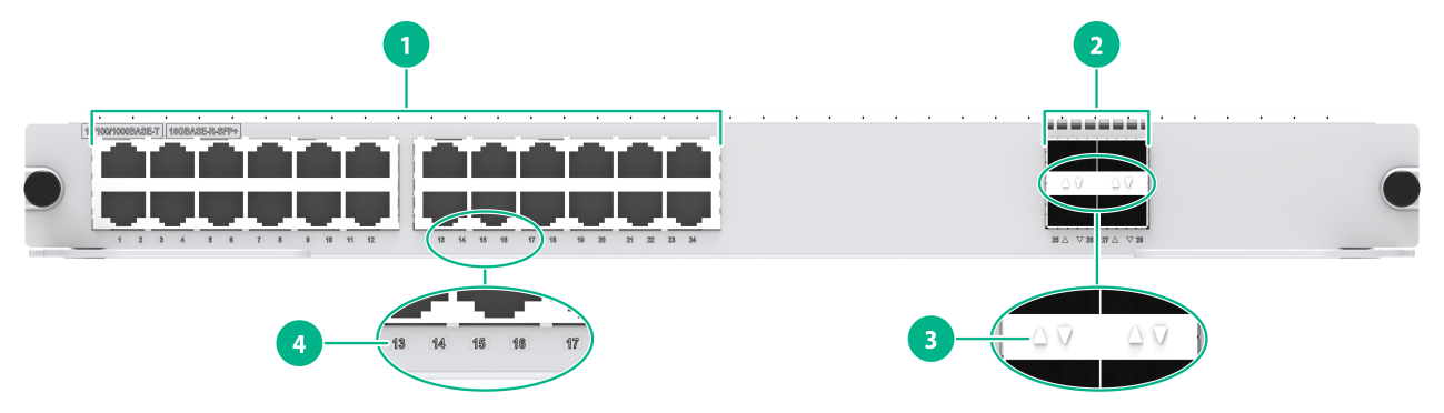
|
(1) 10/100/1000BASE-T ports |
(2) 10GBASE-R-SFP+ fiber ports |
|
(3) 10GBASE-R-SFP+ fiber port LED |
(4) 110/100/1000BASE-T LED |
Table2-78 LED description
|
LED |
Status |
Description |
|
SFP+ Ethernet port LED |
Flashing |
The SFP+ port is receiving or sending data. |
|
On |
A link is present on the SFP+ port. |
|
|
Off |
No link is present on the SFP+ port. |
|
|
RJ-45 Ethernet port LED |
Flashing |
The RJ-45 Ethernet port is receiving or sending data. |
|
On |
A link is present on the RJ-45 Ethernet port. |
|
|
Off |
No link is present on the RJ-45 Ethernet port. |
|
|
NOTE: You can check the SFP+ port speed by observing the color of the SFP+ port LED. Green indicates a speed of 10 Gbps, and yellow indicates a speed of 1000 Mbps. |
LSCM2GV48SC0/LSCM2GV48SD0
When you install an LSCM2GV48SC0 or LSCM2GV48SD0 interface module, order a power module that can be used for setting up a PoE system. The requirements for setting up a PoE system vary by switch model. Make sure the maximum PoE power provided by the power module is greater than the PoE power consumption.
View
Figure2-67 Interface module view (LSCM2GV48SC0 as an example)
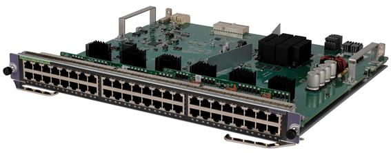
Technical specifications
Table2-79 Technical specifications
|
Item |
LSCM2GV48SC0 |
LSCM2GV48SD0 |
|
Net weight |
2.95 kg (6.50 lb) |
3.00 kg (6.61 lb) |
|
Dimensions (H × W × D) |
40 × 399 × 355 mm (1.57 × 15.71 × 13.98 in) |
|
|
Power consumption |
· Minimum: 27 W · Typical: 37 W · Maximum: 51 W |
|
|
Port quantity |
48 |
|
|
Port type |
10/100/1000BASE-T-PoE+ port |
|
|
Maximum PoE power per port |
Each port provides a maximum power of 30 W for the connected device |
|
|
Maximum PoE power per card |
1440 W |
|
|
Available transceiver modules and cables |
Category 5 twisted pair cables |
|
|
Services |
The card provides data access and forwarding with forty-eight 10/100/1000BASE-T-PoE+ ports |
|
|
Hot swapping |
Supported |
|
Ports and LEDs
Figure2-68 Front panel
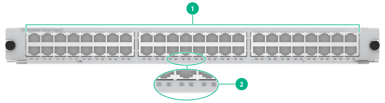
|
(1) 10/100/1000BASE-T-PoE+ ports |
(2) 10/100/1000BASE-T-PoE+ port LED |
Table2-80 LED description
|
LED |
Status |
Description |
|
RJ-45 Ethernet port LED |
Flashing |
The RJ-45 Ethernet port is receiving or sending data. |
|
On |
A link is present on the RJ-45 Ethernet port. |
|
|
Off |
No link is present on the RJ-45 Ethernet port. |
OAA cards
LSCM1FWDSD0
View
Figure2-69 OAA card view
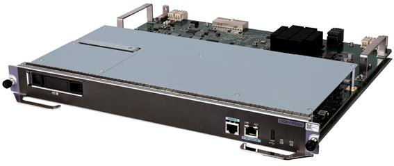
Technical specifications
Table2-81 Technical specifications
|
Item |
Specification |
|
Net weight |
4.20 kg (9.26 lb) |
|
Dimensions (H × W × D) |
40 × 399 × 355 mm (1.57 × 15.71 × 13.98 in) |
|
Power consumption |
· Minimum: 102 W · Typical: 116 W · Maximum: 133 W |
|
Flash |
8MB Nor Flash |
|
Memory |
Standard configuration: 16 GB (two 8GB VLP RDIMMs) |
|
Micro SD card |
One built-in Micro SD card slot Standard configuration: 8 GB |
|
Connector |
· RJ-45 · USB (Type A) |
|
Ports |
· 1 × console port · 1 × USB port · 1 × GE copper port · 1 × hard disk slot |
|
Port transmission speed |
· Console port: 9600 bps (default) to 115200 bps · RJ-45 port: 10/100/1000 Mbps, half/full duplex |
|
Available transceiver modules and cables |
Category 5 twisted pair cables |
|
Hot swapping |
Supported |
Ports and LEDs
Figure2-70 Front panel
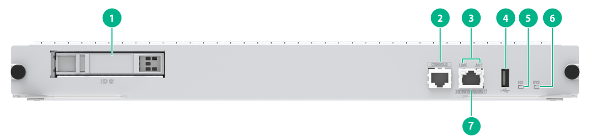
|
(1) Hard disk slot |
(2) Console port |
|
(3) 10/100/1000BASE-T port LEDs |
(4) USB port |
|
(5) Hard disk LED |
(6) System status LED (SYS) |
|
(7) 10/100/1000BASE-T port |
|
Table2-82 LED description
|
LED |
Status |
Description |
|
RJ-45 Ethernet port LEDs |
LINK: Steady on ACT: Flashing |
A link is present, and the port is receiving or sending data. |
|
LINK: Steady on ACT: Off |
A link is present. |
|
|
LINK: Off ACT: Off |
No link is present. |
|
|
Hard disk LED |
Flashing |
The hard disk is reading and writing data. |
|
On |
The hard disk is operating correctly. |
|
|
System status LED |
Off |
No power input or the card is faulty. |
LSCM2FWDSD0
View
Figure2-71 OAA card view
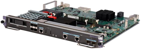
Technical specifications
Table2-83 Technical specifications
|
Item |
Specification |
|
Net weight |
3.40 kg (7.50 lb) |
|
Dimensions (H × W × D) |
40 × 399 × 355 mm (1.57 × 15.71 × 13.98 in) |
|
Power consumption |
· Minimum: 55 W · Typical: 60 W · Maximum: 63 W |
|
Flash |
· 8MB Nor Flash · 1GB Nand Flash |
|
Memory |
Four memory slots Standard configuration: 16 GB (two 8GB VLP RDIMMs) You must install the VLP RDIMMs in pairs and each pair must have the same specifications. |
|
Connector |
· RJ-45 · LC · USB (Type A) |
|
Ports |
· 1 × console port · 2 × USB ports · 2 × combo interfaces. Each combo interface includes: ¡ 1 × 10/100/1000BASE-T copper port ¡ 1 × 1000BASE-X-SFP fiber port · 4 × 10GBASE-R-SFP+ fiber ports · 1 × hard disk slot |
|
Port transmission speed |
· Console port: 9600 bps (default) to 115200 bps · RJ-45 port: 10/100/1000 Mbps, half/full duplex · SFP port: 1 Gbps, 100 Mbps · SFP+ port: 10 Gbps, 1 Gbps |
|
Available transceiver modules and cables |
· 10G SFP+ transceiver modules · 10G SFP+ DAC cables · 100M/1G SFP transceiver modules · Category 5 twisted pair cables |
|
Hot swapping |
Supported |
|
|
NOTE: The two ports of a combo interface cannot operate simultaneously. By default, the copper combo port is activated. You can use the combo enable { copper | fiber } command to activate the copper or fiber combo port. |
Ports and LEDs
Figure2-72 Front panel
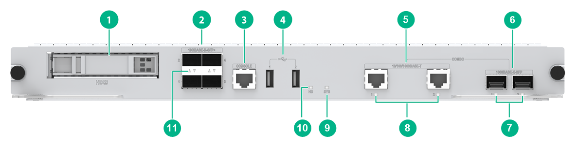
|
(1) Hard disk slot |
(2) 10GBASE-R-SFP+ fiber ports |
|
(3) Console port |
(4) USB ports |
|
(5) Combo interface (10/100/1000BASE-T) |
(6) Combo interface (1000BASE-X-SFP) |
|
(7) Combo interface (1000BASE-X-SFP) LEDs |
(8) Combo interface (10/100/1000BASE-T) LEDs |
|
(9) System status LED (SYS) |
(10) Hard disk LED |
|
(11) 10GBASE-R-SFP+ fiber port LED |
|
Table2-84 LED description
|
LED |
Status |
Description |
|
Combo interface LED |
Flashing |
The port is receiving or sending data. |
|
On |
A link is present. |
|
|
Off |
No link is present. |
|
|
Hard disk LED |
Flashing |
The hard disk is reading and writing data. |
|
On |
The hard disk is operating correctly. |
|
|
System status LED |
Off |
No power input or the card is faulty. |
|
SFP+ port LED |
Flashing |
The SFP+ port is receiving or sending data. |
|
On |
A link is present on the SFP+ port. |
|
|
Off |
No link is present on the SFP+ port. |
OLT interface modules
LSCM2XPG24SF0
View
Figure2-73 Interface module view
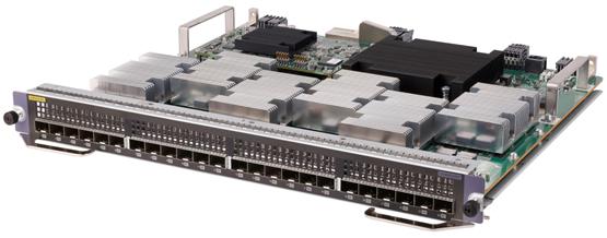
Technical specifications
Table2-85 Technical specifications
|
Item |
Specification |
|
Net weight |
4.10 kg (9.04 lb) |
|
Dimensions (H × W × D) |
40 × 399 × 355 mm (1.57 × 15.71 × 13.98 in) |
|
Power consumption |
· Minimum: 245 W · Typical: 278 W · Maximum: 429 W |
|
Port quantity |
24 |
|
Port type |
XGSPON-D-SFP+ fiber port |
|
Available transceiver modules and cables |
10G XGSPON OLT transceiver modules |
|
Services |
The card provides data access and forwarding with twenty-four XGSPON-D-SFP+ fiber ports |
|
Hot swapping |
Supported |
Ports and LEDs
Figure2-74 Front panel
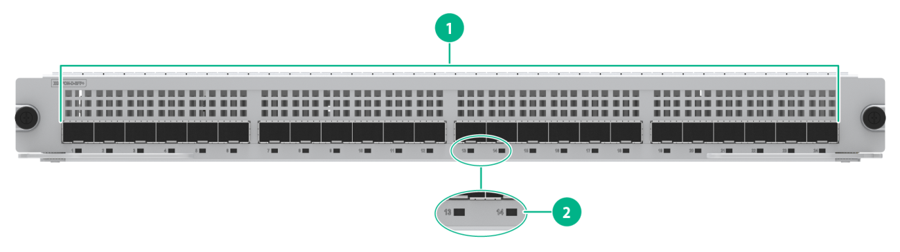
|
(1) XGSPON-D-SFP+ fiber ports |
(2) XGSPON-D-SFP+ fiber port LED |
Table2-86 LED description
|
LED |
Status |
Description |
|
OLT port LED |
On |
An ONU link is present on the OLT port. |
|
Off |
No ONU link is present on the OLT port. |
LSCM2XPT24SF0
View
Figure2-75 Interface module view
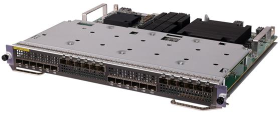
Technical specifications
Table2-87 Technical specifications
|
Item |
Specification |
|
Net weight |
4.45 kg (9.81 lb) |
|
Dimensions (H × W × D) |
40 × 399 × 355 mm (1.57 × 15.71 × 13.98 in) |
|
Power consumption |
· Minimum: 213 W · Typical: 239 W · Maximum: 384 W |
|
Port quantity |
24 |
|
Port type |
10G/1GBASE-PR/PRX-D-SFP+ fiber port |
|
Available transceiver modules and cables |
10G EPON OLT transceiver modules |
|
Services |
The card provides data access and forwarding with twenty-four 10G/1GBASE-PR/PRX-D-SFP+ fiber ports |
|
Hot swapping |
Supported |
Ports and LEDs
Figure2-76 Front panel
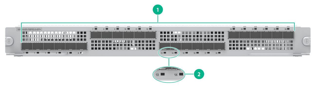
|
(1) 10G/1GBASE-PR/PRX-D-SFP+ fiber ports |
(2) 10G/1GBASE-PR/PRX-D-SFP+ fiber port LED |
Table2-88 LED description
|
LED |
Status |
Description |
|
OLT port LED |
On |
An ONU link is present on the OLT port. |
|
Off |
No ONU link is present on the OLT port. |
3 Power modules
Follow these restrictions and guidelines to configure and use power modules for the switch:
· A chassis must be configured with a minimum of one power module. To improve power supply availability, you can configure a chassis with two power modules for redundancy.
· The power modules installed on the switch must be the same type (AC or DC) and model.
· Make sure the maximum output power of a power module is greater than the total power consumption of the switch. As a best practice, reserve 20% of the maximum output power.
PSR320-A/PSR650-A
View
Figure3-1 Power module view (PSR320-A as an example)
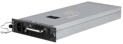
Technical specifications
Table3-1 Technical specifications
|
Item |
PSR320-A |
PSR650-A |
|
Net weight |
2.00 kg (4.41 lb) |
1.90 kg (4.19 lb) |
|
Dimensions (H × W × D) |
40 × 140 × 350 mm (1.57 × 5.51 × 13.78 in, 1 RU) |
|
|
Rated input voltage |
100 to 240 VAC @ 50 or 60 Hz |
100 to 240 VAC @ 50 or 60 Hz |
|
Maximum input current |
5 A |
10 A |
|
Rated output voltage |
12.0 V |
12 V/3.3 V |
|
Maximum output current |
25 A |
54 A (12 V) 4 A (3.3 V) |
|
Maximum output power |
300 W |
650 W |
|
Maximum PoE output power |
N/A |
|
|
Heat dissipation |
Equipped with fans, front-to-rear airflow |
|
|
Hot swapping |
Supported |
|
|
Operating temperature |
–5°C to +55°C (23°F to 131°F) |
0°C to 55°C (32°F to 131°F) |
|
Storage temperature |
–40°C to +70°C (–40°F to +158°F) |
|
|
Applicable switch models |
S7503X-G, S7503X-M-G |
All S7500X-G switch models |
|
|
NOTE: To install a PSR650-A power module on an S7506X-G, S7506X-G-PoE, S7510X-G, or S7510X-G-PoE switch, first insert a power module adapter into the chassis, and then insert the power module into the adapter. |
LEDs
Figure3-2 Front panel (PSR320-A as an example)
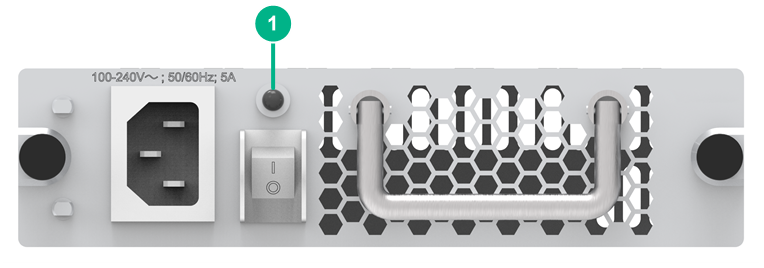
|
(1) Status LED |
Table3-2 LED description
|
LED |
Status |
Description |
|
Status LED |
Green |
The power module is operating correctly. |
|
Red |
Abnormal operation. Possible reasons include: · The power module has an input undervoltage, output shortcircuit, output overcurrent, output overvoltage, or overtemperature alarm and has entered self-protection state. · A power module fan failure has occurred. |
|
|
Off |
Abnormal power input. Possible reasons include: · The power module is faulty. · The power cord is disconnected. · The external power supply system has a power outage. · The power module is switched off. |
PSR650-D
View
Figure3-3 Power module view
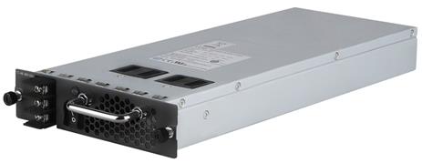
Technical specifications
Table3-3 Technical specifications
|
Item |
Specification |
|
Net weight |
2.30 kg (5.07 lb) |
|
Dimensions (H × W × D) |
40 × 140 × 350 mm (1.57 × 5.51 × 13.78 in, 1 RU) |
|
Rated input voltage |
–48 to –60 VDC |
|
Maximum input current |
25 A |
|
Rated output voltage |
12 V/3.3 V |
|
Maximum output current |
54 A (12 V) 4 A (3.3 V) |
|
Maximum output power |
650 W |
|
Maximum PoE output power |
N/A |
|
Heat dissipation |
Equipped with fans, front-to-rear airflow |
|
Hot swapping |
Supported |
|
Operating temperature |
0°C to 55°C (32°F to 131°F) |
|
Storage temperature |
–40°C to +70°C (–40°F to +158°F) |
|
Applicable switch models |
All S7500X-G switch models |
|
|
NOTE: To install a PSR650-D power module on an S7506X-G, S7506X-G-PoE, S7510X-G, or S7510X-G-PoE switch, first insert a power module adapter into the chassis, and then insert the power module into the adapter. |
LEDs
Figure3-4 Front panel
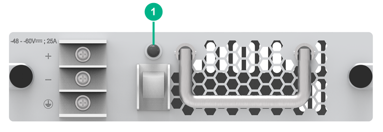
|
(1) Status LED |
Table3-4 LED description
|
LED |
Status |
Description |
|
Status LED |
Green |
The power module is operating correctly. |
|
Red |
Abnormal operation. Possible reasons include: · The power module has an input undervoltage, output shortcircuit, output overcurrent, output overvoltage, or overtemperature alarm and has entered self-protection state. · A power module fan failure has occurred. |
|
|
Off |
Abnormal power input. Possible reasons include: · The power module is faulty. · The power cord is disconnected. · The external power supply system has a power outage. · The power module is switched off. |
PSR650C-12A
View
Figure3-5 Power module view
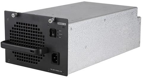
Technical specifications
Table3-5 Technical specifications
|
Item |
Specification |
|
Net weight |
5.15 kg (11.35 lb) |
|
Dimensions (H × W × D) |
128 × 196 × 382 mm (5.04 × 7.72 × 15.04 in, 3 RUs) |
|
Rated input voltage |
100 to 240 VAC @ 50 or 60 Hz |
|
Maximum input current |
10 A |
|
Rated output voltage |
12 V |
|
Maximum output current |
54 A |
|
Maximum output power |
650 W |
|
Maximum PoE output power |
N/A |
|
Heat dissipation |
Equipped with fans, front-to-rear airflow |
|
Hot swapping |
Supported |
|
Operating temperature |
–10°C to +55°C (14°F to 131°F) |
|
Storage temperature |
–40°C to +70°C (–40°F to +158°F) |
|
Applicable switch models |
S7506X-G, S7506X-G-PoE, S7510X-G, S7510X-G-PoE |
LEDs
Figure3-6 Front panel
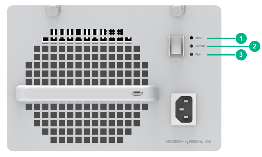
|
(1) Input status LED (INPUT) |
(2) Output status LED (OUTPUT) |
|
(3) Fan status LED (FAN) |
|
Table3-6 LED description
|
LED |
Status |
Description |
|
INPUT |
Green |
Normal power input. |
|
Red |
Abnormal power input. The input voltage is out of the rated voltage range. |
|
|
Off |
No power input. Possible reasons include: · The power module is faulty. · The power cord is disconnected. · The external power supply system has a power outage. |
|
|
OUTPUT |
Green |
Normal power output. |
|
Red |
Abnormal power output. Possible reasons include: · The power module has an input undervoltage, output shortcircuit, output overcurrent, output overvoltage, or overtemperature alarm and has entered self-protection state. · The power module is switched off. |
|
|
Off |
No power output. Possible reasons include: · The power module is faulty. · The power cord is disconnected. · The external power supply system has a power outage. |
|
|
FAN |
Green |
The fan in the power module is operating correctly. |
|
Red |
The fan in the power module is operating incorrectly. Possible reasons include: · A power module fan failure has occurred. · The power module is switched off. |
|
|
Off |
The fan in the power module is not operating. Possible reasons include: · The power module is faulty. · The power cord is disconnected. · The external power supply system has a power outage. |
PSR650C-12D
View
Figure3-7 Power module view
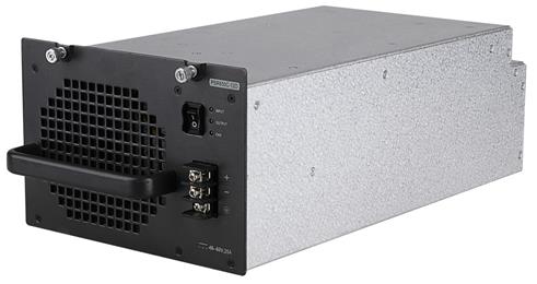
Technical specifications
Table3-7 Technical specifications
|
Item |
Specification |
|
Net weight |
4.20 kg (9.26 lb) |
|
Dimensions (H × W × D) |
128 × 196 × 382 mm (5.04 × 7.72 × 15.04 in, 3 RUs) |
|
Rated input voltage |
–48 to –60 VDC |
|
Maximum input current |
25 A |
|
Rated output voltage |
12 V |
|
Maximum output current |
54 A |
|
Maximum output power |
650 W |
|
Maximum PoE output power |
N/A |
|
Heat dissipation |
Equipped with fans, front-to-rear airflow |
|
Hot swapping |
Supported |
|
Operating temperature |
–10°C to +55°C (14°F to 131°F) |
|
Storage temperature |
–40°C to +70°C (–40°F to +158°F) |
|
Applicable switch models |
S7506X-G, S7506X-G-PoE, S7510X-G, S7510X-G-PoE |
LEDs
Figure3-8 Front panel
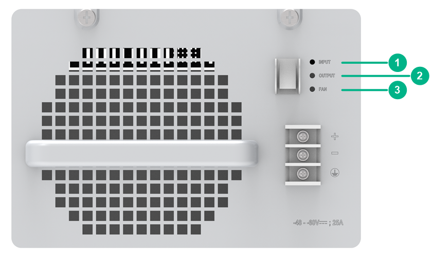
|
(1) Input status LED (INPUT) |
(2) Output status LED (OUTPUT) |
|
(3) Fan status LED (FAN) |
|
Table3-8 LED description
|
LED |
Status |
Description |
|
INPUT |
Green |
Normal power input. |
|
Red |
Abnormal power input. The input voltage is out of the rated voltage range. |
|
|
Off |
No power input. Possible reasons include: · The power module is faulty. · The power cord is disconnected. · The external power supply system has a power outage. |
|
|
OUTPUT |
Green |
Normal power output. |
|
Red |
Abnormal power output. Possible reasons include: · The power module has an input undervoltage, output shortcircuit, output overcurrent, output overvoltage, or overtemperature alarm and has entered self-protection state. · The power module is switched off. |
|
|
Off |
No power output. Possible reasons include: · The power module is faulty. · The power cord is disconnected. · The external power supply system has a power outage. |
|
|
FAN |
Green |
The fan in the power module is operating correctly. |
|
Red |
The fan in the power module is operating incorrectly. Possible reasons include: · A power module fan failure has occurred. · The power module is switched off. |
|
|
Off |
The fan in the power module is not operating. Possible reasons include: · The power module is faulty. · The power cord is disconnected. · The external power supply system has a power outage. |
PSR1200-A
View
Figure3-9 Power module view
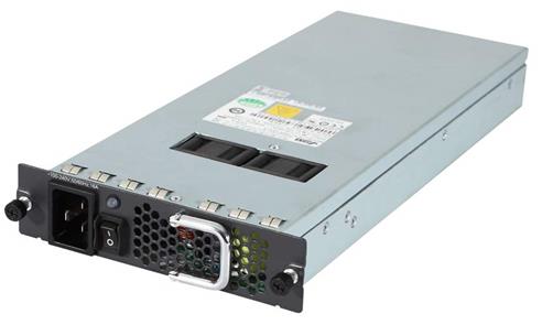
Technical specifications
Table3-9 Technical specifications
|
Item |
Specification |
|
Net weight |
2.56 kg (5.64 lb) |
|
Dimensions (H × W × D) |
40 × 140 × 350 mm (1.57 × 5.51 × 13.78 in, 1 RU) |
|
Rated input voltage |
100 to 240 VAC @ 50 or 60 Hz |
|
Maximum input current |
16 A |
|
Rated output voltage |
12 V/3.3 V |
|
Maximum output current |
100 A (12 V) 4 A (3.3 V) |
|
Maximum output power |
1213 W |
|
Maximum PoE output power |
N/A |
|
Heat dissipation |
Equipped with fans, front-to-rear airflow |
|
Hot swapping |
Supported |
|
Operating temperature |
–10°C to +55°C (14°F to 131°F) |
|
Storage temperature |
–40°C to +70°C (–40°F to +158°F) |
|
Applicable switch models |
S7506X-G, S7506X-G-PoE, S7510X-G, S7510X-G-PoE |
|
|
NOTE: To install a PSR1200-A power module on an S7506X-G, S7506X-G-PoE, S7510X-G, or S7510X-G-PoE switch, first insert a power module adapter into the chassis, and then insert the power module into the adapter. |
LEDs
Figure3-10 Front panel
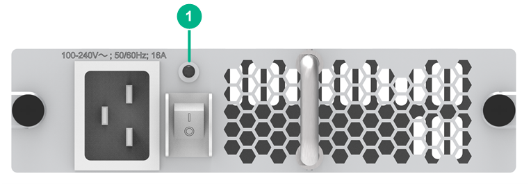
|
(1) Status LED |
Table3-10 LED description
|
LED |
Status |
Description |
|
Status LED |
Green |
The power module is operating correctly. |
|
Red |
Abnormal operation. Possible reasons include: · The power module has an input undervoltage, output shortcircuit, output overcurrent, output overvoltage, or overtemperature alarm and has entered self-protection state. · A power module fan failure has occurred. |
|
|
Off |
Abnormal power input. Possible reasons include: · The power module is faulty. · The power cord is disconnected. · The external power supply system has a power outage. · The power module is switched off. |
PSR1200-D
View
Figure3-11 Power module view
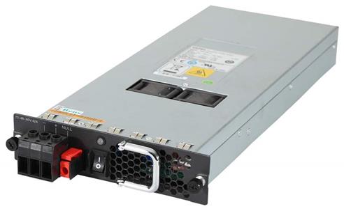
Technical specifications
Table3-11 Technical specifications
|
Item |
Specification |
|
Net weight |
2.51 kg (5.53 lb) |
|
Dimensions (H × W × D) |
40 × 140 × 350 mm (1.57 × 5.51 × 13.78 in, 1 RU) |
|
Rated input voltage |
–48 to –60 VDC |
|
Maximum input current |
42 A |
|
Rated output voltage |
12 V/3.3 V |
|
Maximum output current |
100 A (12 V) 4 A (3.3 V) |
|
Maximum output power |
1213 W |
|
Maximum PoE output power |
N/A |
|
Heat dissipation |
Equipped with fans, front-to-rear airflow |
|
Hot swapping |
Supported |
|
Operating temperature |
–10°C to +55°C (14°F to 131°F) |
|
Storage temperature |
–40°C to +70°C (–40°F to +158°F) |
|
Applicable switch models |
S7506X-G, S7506X-G-PoE, S7510X-G, S7510X-G-PoE |
|
|
NOTE: To install a PSR1200-D power module on an S7506X-G, S7506X-G-PoE, S7510X-G, or S7510X-G-PoE switch, first insert a power module adapter into the chassis, and then insert the power module into the adapter. |
LEDs
Figure3-12 Front panel
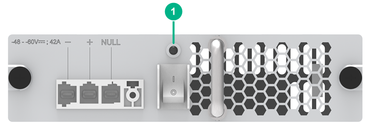
|
(1) Status LED |
Table3-12 LED description
|
LED |
Status |
Description |
|
Status LED |
Green |
The power module is operating correctly. |
|
Red |
Abnormal operation. Possible reasons include: · The power module has an input undervoltage, output shortcircuit, output overcurrent, output overvoltage, or overtemperature alarm and has entered self-protection state. · A power module fan failure has occurred. |
|
|
Off |
Abnormal power input. Possible reasons include: · The power module is faulty. · The power cord is disconnected. · The external power supply system has a power outage. · The power module is switched off. |
PSR1400-A/PSR1400-12A1-F
View
Figure3-13 Power module view (PSR1400-A as an example)
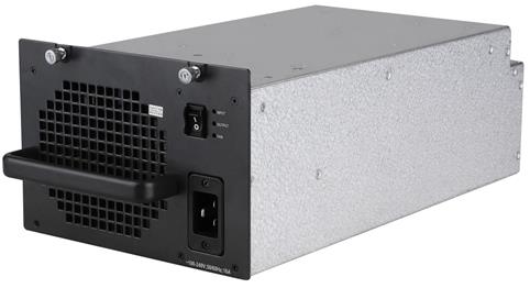
Technical specifications
Table3-13 Technical specifications
|
Item |
PSR1400-A |
PSR1400-12A1-F |
|
Net weight |
8.30 kg (18.30 lb) |
4.30 kg (9.48 lb) |
|
Dimensions (H × W × D) |
128 × 196 × 382 mm (5.04 × 7.72 × 15.04 in, 3 RUs) |
|
|
Rated input voltage |
100 to 240 VAC @ 50 or 60 Hz |
|
|
Maximum input current |
16 A |
16 A |
|
Rated output voltage |
12 V |
|
|
Maximum output current |
117 A |
|
|
Maximum output power |
1150 W (110 VAC) 1400 W (220 VAC) |
1150 W (110 VAC) 1400 W (220 VAC, 270 VDC) |
|
Maximum PoE output power |
N/A |
|
|
Heat dissipation |
Equipped with fans, front-to-rear airflow |
|
|
Hot swapping |
Supported |
|
|
Operating temperature |
–5°C to +55°C (23°F to 131°F) |
|
|
Storage temperature |
–40°C to +70°C (–40°F to +158°F) |
|
|
Applicable switch models |
S7506X-G, S7506X-G-PoE, S7510X-G, S7510X-G-PoE |
|
LEDs
Figure3-14 Front panel
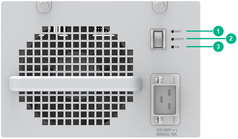
|
(1) Input status LED (INPUT) |
(2) Output status LED (OUTPUT) |
|
(3) Fan status LED (FAN) |
|
Table3-14 LED description
|
LED |
Status |
Description |
|
INPUT |
Green |
Normal power input. |
|
Red |
Abnormal power input. The input voltage is out of the rated voltage range. |
|
|
Off |
No power input. Possible reasons include: · The power module is faulty. · The power cord is disconnected. · The external power supply system has a power outage. |
|
|
OUTPUT |
Green |
Normal power output. |
|
Red |
Abnormal power output. Possible reasons include: · The power module has an input undervoltage, output shortcircuit, output overcurrent, output overvoltage, or overtemperature alarm and has entered self-protection state. · The power module is switched off. |
|
|
Off |
No power output. Possible reasons include: · The power module is faulty. · The power cord is disconnected. · The external power supply system has a power outage. |
|
|
FAN |
Green |
The fan in the power module is operating correctly. |
|
Red |
The fan in the power module is operating incorrectly. Possible reasons include: · A power module fan failure has occurred. · The power module is switched off. |
|
|
Off |
The fan in the power module is not operating. Possible reasons include: · The power module is faulty. · The power cord is disconnected. · The external power supply system has a power outage. |
PSR1400-12D1
View
Figure3-15 Power module view
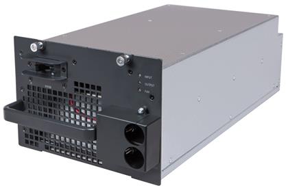
Technical specifications
Table3-15 Technical specifications
|
Item |
Specification |
|
Net weight |
4.20 kg (9.26 lb) |
|
Dimensions (H × W × D) |
128 × 196 × 382 mm (5.04 × 7.72 × 15.04 in, 3 RUs) |
|
Rated input voltage |
–48 to –60 VDC |
|
Maximum input current |
50 A |
|
Rated output voltage |
12 V |
|
Maximum output current |
117 A |
|
Maximum output power |
1400 W |
|
Maximum PoE output power |
N/A |
|
Heat dissipation |
Equipped with fans, front-to-rear airflow |
|
Hot swapping |
Supported |
|
Operating temperature |
–5°C to +55°C (23°F to 131°F) |
|
Storage temperature |
–40°C to +70°C (–40°F to +158°F) |
|
Applicable switch models |
S7506X-G, S7506X-G-PoE, S7510X-G, S7510X-G-PoE |
LEDs
Figure3-16 Front panel
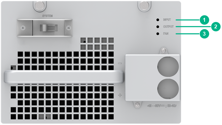
|
(1) Input status LED (INPUT) |
(2) Output status LED (OUTPUT) |
|
(3) Fan status LED (FAN) |
|
Table3-16 LED description
|
LED |
Status |
Description |
|
INPUT |
Green |
Normal power input. |
|
Red |
Abnormal power input. The input voltage is out of the rated voltage range. |
|
|
Off |
No power input. Possible reasons include: · The power module is faulty. · The power cord is disconnected. · The external power supply system has a power outage. · The system power output switch is turned off. |
|
|
OUTPUT |
Green |
Normal power output. |
|
Red |
Abnormal power output. The power module has an output shortcircuit, output overcurrent, output overvoltage, or overtemperature alarm and has entered self-protection state. |
|
|
Off |
No power output. Possible reasons include: · The power module is faulty. · The power cord is disconnected. · The external power supply system has a power outage. · The system power output switch is turned off. |
|
|
FAN |
Green |
The fan in the power module is operating correctly. |
|
Red |
The fan in the power module is operating incorrectly. A power module fan failure has occurred. |
|
|
Off |
The fan in the power module is not operating. Possible reasons include: · The power module is faulty. · The power cord is disconnected. · The external power supply system has a power outage. · The system power output switch is turned off. |
PSR2500-12D
View
Figure3-17 Power module view
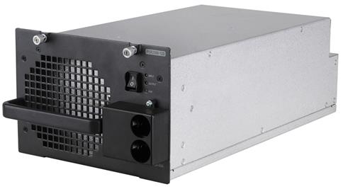
Technical specifications
Table3-17 Technical specifications
|
Item |
Specification |
|
Net weight |
5.55 kg (12.24 lb) |
|
Dimensions (H × W × D) |
128 × 196 × 382 mm (5.04 × 7.72 × 15.04 in, 3 RUs) |
|
Rated input voltage |
–48 to –60 VDC |
|
Maximum input current |
85 A |
|
Rated output voltage |
12 V |
|
Maximum output current |
208 A |
|
Maximum output power |
2500 W |
|
Maximum PoE output power |
N/A |
|
Heat dissipation |
Equipped with fans, front-to-rear airflow |
|
Hot swapping |
Supported |
|
Operating temperature |
–10°C to +55°C (14°F to 131°F) |
|
Storage temperature |
–40°C to +70°C (–40°F to +158°F) |
|
Applicable switch models |
S7506X-G, S7506X-G-PoE, S7510X-G, S7510X-G-PoE |
LEDs
Figure3-18 Front panel
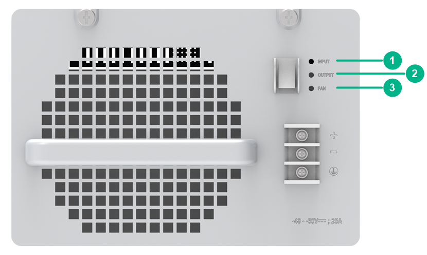
|
(1) Input status LED (INPUT) |
(2) Output status LED (OUTPUT) |
|
(3) Fan status LED (FAN) |
|
Table3-18 LED description
|
LED |
Status |
Description |
|
INPUT |
Green |
Normal power input. |
|
Red |
Abnormal power input. The input voltage is out of the rated voltage range. |
|
|
Off |
No power input. Possible reasons include: · The power module is faulty. · The power cord is disconnected. · The external power supply system has a power outage. |
|
|
OUTPUT |
Green |
Normal power output. |
|
Red |
Abnormal power output. Possible reasons include: · The power module has an input undervoltage, output shortcircuit, output overcurrent, output overvoltage, or overtemperature alarm and has entered self-protection state. · The power module is switched off. |
|
|
Off |
No power output. Possible reasons include: · The power module is faulty. · The power cord is disconnected. · The external power supply system has a power outage. |
|
|
FAN |
Green |
The fan in the power module is operating correctly. |
|
Red |
The fan in the power module is operating incorrectly. Possible reasons include: · A power module fan failure has occurred. · The power module is switched off. |
|
|
Off |
The fan in the power module is not operating. Possible reasons include: · The power module is faulty. · The power cord is disconnected. · The external power supply system has a power outage. |
PSR2500-12AHD
View
Figure3-19 Power module view
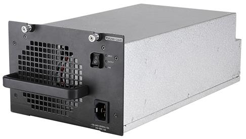
Technical specifications
Table3-19 Technical specifications
|
Item |
Specification |
|
Net weight |
5.45 kg (12.02 lb) |
|
Dimensions (H × W × D) |
128 × 196 × 382 mm (5.04 × 7.72 × 15.04 in, 3 RUs) |
|
Rated input voltage |
100 to 240 VAC @ 50 or 60 Hz 240 to 380 VDC |
|
Maximum input current |
16 A |
|
Rated output voltage |
12 V |
|
Maximum output current |
100 A (100 to 180 VAC) 208 A (180 to 290 VAC, 180 to 400 VDC) |
|
Maximum output power |
2500 W |
|
Maximum PoE output power |
N/A |
|
Heat dissipation |
Equipped with fans, front-to-rear airflow |
|
Hot swapping |
Supported |
|
Operating temperature |
–10°C to +55°C (14°F to 131°F) |
|
Storage temperature |
–40°C to +70°C (–40°F to +158°F) |
|
Applicable switch models |
S7506X-G, S7506X-G-PoE, S7510X-G, S7510X-G-PoE |
LEDs
Figure3-20 Front panel
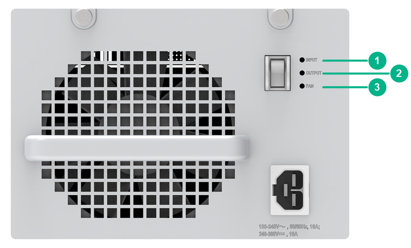
|
(1) Input status LED (INPUT) |
(2) Output status LED (OUTPUT) |
|
(3) Fan status LED (FAN) |
|
Table3-20 LED description
|
LED |
Status |
Description |
|
INPUT |
Green |
Normal power input. |
|
Red |
Abnormal power input. The input voltage is out of the rated voltage range. |
|
|
Off |
No power input. Possible reasons include: · The power module is faulty. · The power cord is disconnected. · The external power supply system has a power outage. |
|
|
OUTPUT |
Green |
Normal power output. |
|
Red |
Abnormal power output. Possible reasons include: · The power module has an input undervoltage, output shortcircuit, output overcurrent, output overvoltage, or overtemperature alarm and has entered self-protection state. · The power module is switched off. |
|
|
Off |
No power output. Possible reasons include: · The power module is faulty. · The power cord is disconnected. · The external power supply system has a power outage. |
|
|
FAN |
Green |
The fan in the power module is operating correctly. |
|
Red |
The fan in the power module is operating incorrectly. Possible reasons include: · A power module fan failure has occurred. · The power module is switched off. |
|
|
Off |
The fan in the power module is not operating. Possible reasons include: · The power module is faulty. · The power cord is disconnected. · The external power supply system has a power outage. |
PSR2800-ACV/PSR2800-A1-F
View
Figure3-21 Power module view (PSR2800-ACV as an example)
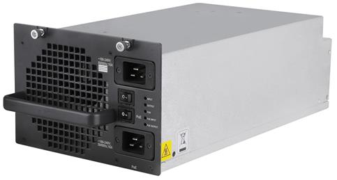
Technical specifications
Table3-21 Technical specifications
|
Item |
PSR2800-ACV |
PSR2800-A1-F |
|
Net weight |
8.00 kg (17.64 lb) |
5.45 kg (12.02 lb) |
|
Dimensions (H × W × D) |
128 × 196 × 382 mm (5.04 × 7.72 × 15.04 in, 3 RUs) |
|
|
Rated input voltage |
100 to 240 VAC @ 50 or 60 Hz |
AC input: 100 to 240 VAC @ 50 or 60 Hz HVDC input: 270 VDC |
|
Maximum input current |
16 A |
|
|
Rated output voltage |
· 12 V · PoE: –50 V |
|
|
Maximum output current |
· 117 A · PoE: 28 A |
|
|
Maximum output power |
1150 W (110 VAC) 1400 W (220 VAC) |
1150 W (110 VAC) 1400 W (220 VAC, 270 VDC) |
|
Maximum PoE output power |
1150 W (110 VAC) 1400 W (220 VAC) |
1150 W (110 VAC) 1400 W (220 VAC, 270 VDC) |
|
Heat dissipation |
Equipped with fans, front-to-rear airflow |
|
|
Hot swapping |
Supported |
|
|
Operating temperature |
–10°C to +55°C (14°F to 131°F) |
|
|
Storage temperature |
–40°C to +70°C (–40°F to +158°F) |
|
|
Applicable switch models |
S7506X-G-PoE, S7510X-G-PoE |
|
LEDs
Figure3-22 Front panel
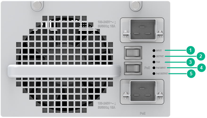
|
(1) Input status LED (INPUT) |
(2) Output status LED (OUTPUT) |
|
(3) Fan status LED (FAN) |
(4) PoE input status LED (PoE INPUT) |
|
(4) PoE output status LED (PoE OUTPUT) |
|
Table3-22 LED description
|
LED |
Status |
Description |
|
INPUT |
Green |
Normal power input. |
|
Red |
Abnormal power input. The input voltage is out of the rated voltage range. |
|
|
Off |
· The power module is faulty. · No power input. Possible reasons include: ¡ The power cord is disconnected. ¡ The external power supply system has a power outage. |
|
|
OUTPUT |
Green |
Normal power output. |
|
Red |
Abnormal power output. Possible reasons include: · The power module has an input undervoltage, output shortcircuit, output overcurrent, output overvoltage, or overtemperature alarm and has entered self-protection state. · The power module is switched off. |
|
|
Off |
· The power module is faulty. · No power input. Possible reasons include: ¡ The power cord is disconnected. ¡ The external power supply system has a power outage. |
|
|
FAN |
Green |
The fan in the power module is operating correctly. |
|
Red |
The fan in the power module is operating incorrectly. Possible reasons include: · A power module fan failure has occurred. · The system power switch is turned off. |
|
|
Off |
· The power module is faulty. · The power module does have power input. Possible reasons include: ¡ The power cord is disconnected. ¡ The external power supply system has a power outage. |
|
|
PoE INPUT |
Green |
Normal PoE power input. |
|
Red |
Abnormal PoE power input. The PoE input voltage is out of the rated voltage range. |
|
|
Off |
No PoE power input. Possible reasons include: · The power module is faulty. · The power cord is disconnected. · The external power supply system has a power outage. |
|
|
PoE OUTPUT |
Green |
Normal PoE power output. |
|
Red |
Abnormal PoE power output. Possible reasons include: · The PoE output voltage is out of the rated voltage range. · The PoE power switch is turned off. |
|
|
Off |
No PoE power output. Possible reasons include: · The power module is faulty. · The PoE input power cord is disconnected. · The external power supply system has a power outage. |
PSR6000-ACV
View
Figure3-23 Power module view
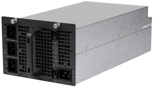
Technical specifications
Table3-23 Technical specifications
|
Item |
Specification |
|
Net weight |
12.16 kg (26.81 lb) |
|
Dimensions (H × W × D) |
128 × 196 × 382 mm (5.04 × 7.72 × 15.04 in, 3 RUs) |
|
Rated input voltage |
100 to 240 VAC @ 50 or 60 Hz |
|
Maximum input current |
16 A |
|
Rated output voltage |
· 12 V · PoE: 48 VDC |
|
Maximum output current |
110 V input: · 12 V output: 96 A · PoE1: 23 A · PoE2: 46 A · PoE3: 69 A 220 V input: · 12 V output: 117 A · PoE1: 34 A · PoE2: 68 A · PoE3: 100 A |
|
Maximum output power |
1150 W (110 VAC) 1400 W (220 VAC) |
|
Maximum PoE output power |
110 V input: · PoE1: 1200 W · PoE2: 2400 W · PoE3: 3600 W 220 V input: · PoE1: 1800 W · PoE2: 3600 W · PoE3: 5400 W |
|
Heat dissipation |
Equipped with fans, front-to-rear airflow |
|
Hot swapping |
Supported |
|
Operating temperature |
0°C to 45°C (32°F to 113°F) |
|
Storage temperature |
–40°C to +70°C (–40°F to +158°F) |
|
Applicable switch models |
S7506X-G-PoE, S7510X-G-PoE |
LEDs
Figure3-24 Front panel
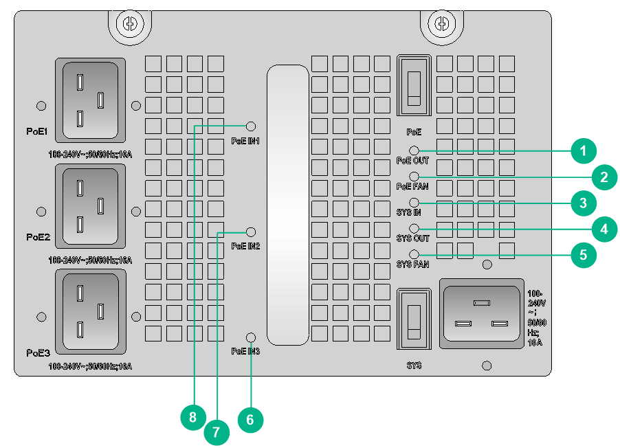
|
(1) PoE output status LED (PoE OUT) |
(2) PoE fan status LED (PoE FAN) |
|
(3) System power input status LED (SYS IN) |
(4) System power output status LED (SYS OUT) |
|
(5) System fan status LED (SYS FAN) |
(6) PoE input status LED (PoE IN1) |
|
(7) PoE input status LED (PoE IN2) |
(8) PoE input status LED (PoE IN3) |
Table3-24 LED description
|
LED mark |
Status |
Description |
|
SYS IN |
Green |
Normal system power input. |
|
Red |
Abnormal system power input. The input voltage is out of the rated voltage range. |
|
|
Off |
· The power module is faulty. · No power input. Possible reasons include: ¡ The power cord is disconnected. ¡ The external power supply system has a power outage. |
|
|
SYS OUT |
Green |
Normal system power output. |
|
Red |
Abnormal system power output. Possible reasons include: · The power module has an input undervoltage, output shortcircuit, output overcurrent, output overvoltage, or overtemperature alarm and has entered self-protection state. · The power module is switched off. |
|
|
Off |
· The power module is faulty. · No power input. Possible reasons include: ¡ The power cord is disconnected. ¡ The external power supply system has a power outage. |
|
|
SYS FAN |
Green |
The fan in the power module is operating correctly. |
|
Red |
The fan in the power module is operating incorrectly. Possible reasons include: · A power module fan failure has occurred. · The system power switch is turned off. |
|
|
Off |
· The power module is faulty. · The power module does have power input. Possible reasons include: ¡ The power cord is disconnected. ¡ The external power supply system has a power outage. |
|
|
PoE IN1 |
Green |
Normal PoE1 power input. |
|
Red |
Abnormal PoE1 power input. The PoE1 input voltage is out of the rated voltage range. |
|
|
Off |
No PoE1 power input. Possible reasons include: · The power module is faulty. · The power cord is disconnected. · The external power supply system has a power outage. |
|
|
PoE IN2 |
Green |
Normal PoE2 power input. |
|
Red |
Abnormal PoE2 power input. The PoE2 input voltage is out of the rated voltage range. |
|
|
Off |
No PoE2 power input. Possible reasons include: · The power module is faulty. · The power cord is disconnected. · The external power supply system has a power outage. |
|
|
PoE IN3 |
Green |
Normal PoE3 power input. |
|
Red |
Abnormal PoE3 power input. The PoE3 input voltage is out of the rated voltage range. |
|
|
Off |
No PoE3 power input. Possible reasons include: · The power module is faulty. · The power cord is disconnected. · The external power supply system has a power outage. |
|
|
PoE OUT |
Green |
Normal PoE power output. |
|
Red |
Abnormal PoE power output. Possible reasons include: · The power module has an output shortcircuit, output overcurrent, output overvoltage, or overtemperature alarm and has entered self-protection state. · The PoE power switch is turned off. |
|
|
Off |
No PoE power output. Possible reasons include: · The power module is faulty. · The PoE1, PoE2, and PoE3 input power cords are disconnected. · The external power supply system has a power outage. |
|
|
PoE FAN |
Green |
The PoE fan in the power module is operating correctly. |
|
Red |
The PoE fan in the power module is operating incorrectly. Possible reasons include: · A power module fan failure has occurred. · The system power switch is turned off. |
|
|
Off |
· The power module is faulty. · The power module does have power input. Possible reasons include: ¡ The PoE1, PoE2, and PoE3 input power cords are disconnected. ¡ The external power supply system has a power outage. |
LSQM1PWRSPB power module adapter
View
Figure3-25 Power module adapter view
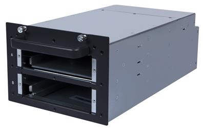
Technical specifications
Table3-25 Technical specifications
|
Item |
Specification |
|
Net weight |
4.95 kg (10.91 lb) |
|
Dimensions (H × W × D) |
128 × 196 × 382 mm (5.04 × 7.72 × 15.04 in) |
|
Applicable switch models |
S7506X-G, S7506X-G-PoE, S7510X-G, S7510X-G-PoE |
4 Fan trays
The switch came with the fan tray installed. To replace the fan tray, make sure the new fan tray is compatible with the switch.
The switch uses fan trays that can automatically adjust the fan speed based on the heat dissipation condition of the switch. The power consumed by a fan tray varies by fan speed.
LSQM103MFAN
View
Figure4-1 Fan tray view
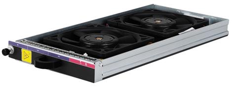
Technical specifications
Table4-1 Technical specifications
|
Item |
Specification |
|
Net weight |
1.00 kg (2.20 lb) |
|
Dimensions (H × W × D) |
29 × 167 × 377 mm (1.14 × 6.57 × 14.84 in) |
|
Power consumption |
· Minimum: 7 W · Maximum: 11 W |
|
Number of fans |
2 |
|
Fan diameter |
120 mm (4.72 in) |
|
Maximum air flow rate |
150 CFM (4.25 m3/min) |
|
Airflow direction |
Left-to-right |
|
Hot swapping |
Supported |
|
Auto speed adjustment |
Supported |
|
Alarm detection |
Supported |
|
Applicable switch models |
S7503X-G |
FAN-92-3-A
View
Figure4-2 Fan tray view
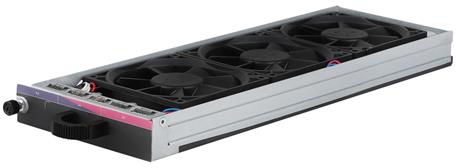
Technical specifications
Table4-2 Technical specifications
|
Item |
Specification |
|
Net weight |
0.80 kg (1.76 lb) |
|
Dimensions (H × W × D) |
30 × 127 × 351 mm (1.18 × 5.00 × 13.82 in) |
|
Power consumption |
· Minimum: 7.5 W · Maximum: 14.5 W |
|
Number of fans |
3 |
|
Fan diameter |
92 mm (3.62 in) |
|
Maximum air flow rate |
165 CFM (4.67 m3/min) |
|
Airflow direction |
Left-to-right |
|
Hot swapping |
Supported |
|
Auto speed adjustment |
Supported |
|
Alarm detection |
Supported |
|
Applicable switch models |
S7503X-M-G |
FAN-80/92-3-A (with two types of fans)
View
Figure4-3 Fan tray view
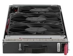
Technical specifications
Table4-3 Technical specifications
|
Item |
Specification |
|
Net weight |
0.70 kg (1.54 lb) |
|
Dimensions (H × W × D) |
30 × 127 × 351 mm (1.18 × 5.00 × 13.82 in) |
|
Power consumption |
· Minimum: 7 W · Maximum: 14 W |
|
Number of fans |
3 |
|
Fan diameter |
· 80 mm (3.15 in) · 92 mm (3.62 in) |
|
Maximum air flow rate |
130 CFM (3.68 m3/min) |
|
Airflow direction |
Left-to-right |
|
Hot swapping |
Supported |
|
Auto speed adjustment |
Supported |
|
Alarm detection |
Supported |
|
Applicable switch models |
S7506X-G-MF |
LSQM106HFAN/LSQM106HFAN-G3
View
Figure4-4 Fan tray view (LSQM106HFAN as an example)
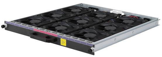
Technical specifications
Table4-4 Technical specifications
|
Item |
LSQM106HFAN |
LSQM106HFAN-G3 |
|
Net weight |
2.20 kg (4.85 lb) |
2.10 kg (4.63 lb) |
|
Dimensions (H × W × D) |
29 × 347 × 367 mm (1.14 × 13.66 × 14.45 in) |
|
|
Power consumption |
· Minimum: 24.5 W · Maximum: 42.5 W |
|
|
Number of fans |
9 |
|
|
Fan diameter |
92 mm (3.62 in) |
|
|
Maximum air flow rate |
495 CFM (14.02 m3/min) |
|
|
Airflow direction |
Left-to-right |
|
|
Hot swapping |
Supported |
|
|
Auto speed adjustment |
Supported |
|
|
Alarm detection |
Supported |
|
|
Applicable switch models |
S7506X-G, S7506X-G-PoE |
|
LSQM17510EFAN/LSQM17510EFAN-G3
View
Figure4-5 Fan tray view (LSQM17510EFAN as an example)
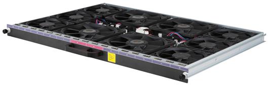
Technical specifications
Table4-5 Technical specifications
|
Item |
LSQM17510EFAN |
LSQM17510EFAN-G3 |
|
Net weight |
2.90 kg (6.39 lb) |
2.70 kg (5.95 lb) |
|
Dimensions (H × W × D) |
287 × 497 × 351 mm (11.30 × 19.57 × 13.82 in) |
|
|
Power consumption |
· Minimum: 28 W · Maximum: 48.5 W |
|
|
Number of fans |
6+4 |
|
|
Fan diameter |
· Small fan: 92 mm (3.62 in) · Large fan: 120 mm (4.72 in) |
|
|
Maximum air flow rate |
662 CFM (18.75 m3/min) |
|
|
Airflow direction |
Left-to-right |
|
|
Hot swapping |
Supported |
|
|
Auto speed adjustment |
Supported |
|
|
Alarm detection |
Supported |
|
|
Applicable switch models |
S75010X-G, S75010X-G-PoE |
|
5 Cables
This chapter describes the cables used for connecting network ports.
Table5-1 Cable description
|
Cable |
Port type |
Application |
|
Console cable |
Console port at one end and 9-pin serial port at the other end |
Enables users to perform debugging, configuration, maintenance, management, and software loading on the device. For more information, see H3C S7500X-G Switch Series Installation Guide. |
|
USB console cable |
USB console port at one end and USB port at the other end |
|
|
N/A |
Connects a DC power module to an external DC power source. |
|
|
N/A |
Connects an AC power module to an external AC power source. |
|
|
RJ-45 Ethernet ports |
Connects RJ-45 Ethernet ports to transmit data. |
|
|
SFP/SFP+/SFP28/QSFP+/QSFP28 ports |
Connects the fiber ports to transmit data. |
|
|
SFP+ ports |
Connects SFP+ ports to transmit data. |
|
|
SFP28 ports |
Connects SFP28 ports to transmit data. |
|
|
SFP28 ports |
Connects SFP28 ports to transmit data. |
|
|
QSFP+ ports |
Connects QSFP+ ports to transmit data. |
|
|
QSFP+ ports |
Connects QSFP+ ports to transmit data. |
|
|
QSFP28 ports |
Connects QSFP28 ports to transmit data. |
|
|
QSFP28 ports |
Connects QSFP28 ports to transmit data. |
|
|
QSFP+ port at one end, and SFP+ port at the other end |
Connects a QSFP+ port to an SFP+ port. |
|
|
QSFP28 port at one end, and SFP28 port at the other end |
Connects a QSFP28 port to an SFP28 port. |
DC power cord
A DC power cord connects a DC power module to an external DC power source.
Table5-2 DC power cords available for the power modules
|
DC power module |
DC power cord code |
DC power cord length |
|
PSR650-D/PSR650C-12D |
0404A06T |
3 m (9.84 ft) (provided) |
|
0404A01N |
5 m (16.40 ft) |
|
|
0404A01P |
10 m (32.81 ft) |
|
|
0404A073 |
20 m (65.62 ft) |
|
|
PSR1400-12D1/PSR2500-12D |
0404A07G |
3 m (9.84 ft) (provided) |
|
0404A08T |
10 m (32.81 ft) |
|
|
0404A08U |
20 m (65.62 ft) |
|
|
0404A072 |
25 m (82.02 ft) |
|
|
PSR1200-D |
0404A0DU |
3 m (9.84 ft) |
|
PSR2500-12AHD |
0404A0RL |
3 m (9.84 ft) |
AC power cord
An AC power cord connects an AC power module to an external AC power source.
· Select an AC power cord with a current-carrying capacity that meets the power supply requirement.
· For the PSR2500-12AHD power module, select the 0404A0RP or 0404A0RQ AC power cord.
· For the PSR650-A, PSR320-A, and PSR650C-12A power modules, select 10A AC power cords. For the PSR1200-A, PSR1400-A, PSR1400-12A1-F, PSR2800-ACV, and PSR2800-A1-F power modules, select 16A AC power cords.
· The type of the connector (connected to the power source) varies by country or region. Select a compliant connector type as needed. For the connector types of different countries or regions and the power cord codes, see H3C Power Cords & Cables User Guide.
Ethernet twisted pair cable
An Ethernet twisted pair cable consists of four pairs of insulated wires twisted together. It mainly transmits analog signals and is advantageous in transmitting data over shorter distances. The maximum transmission distance is 100 m (328.08 ft).
RJ-45 connector
An Ethernet twisted pair cable connects network devices through the RJ-45 connectors at the two ends. Figure5-1 shows the pinouts of an RJ-45 connector.
Figure5-1 RJ-45 connector pinout diagram
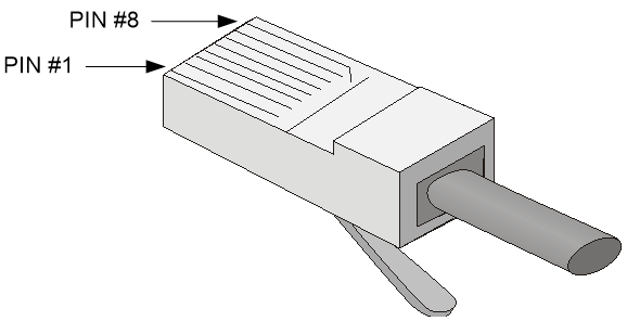
Cable pinouts
EIA/TIA cabling specifications define two standards: 568A and 568B for cable pinouts.
· Standard 568A—Pin 1: white/green stripe, pin 2: green solid, pin 3: white/orange stripe, pin 4: blue solid, pin 5: white/blue stripe, pin 6: orange solid, pin 7: white/brown stripe, pin 8: brown solid.
· Standard 568B—Pin 1: white/orange stripe, pin 2: orange solid, pin 3: white/green stripe, pin 4: blue solid, pin 5: white/blue stripe, pin 6: green solid, pin 7: white/brown stripe, pin 8: brown solid.
Cable type
Based on performance
Table5-3 Ethernet cable description
|
Type |
Description |
|
Category 5 |
Transmits data at a maximum speed of 100 Mbps, with a bandwidth of 100 MHz. |
|
Category 5e |
Transmits data at a maximum speed of 1000 Mbps, with a bandwidth of 100 MHz. |
|
Category 6 |
Transmits data at a maximum speed of 10 Gbps, with a bandwidth of 250 MHz. |
|
|
NOTE: The RJ-45 Ethernet ports use category 5 or higher Ethernet twisted pair cables for connection. |
Based on pinouts
Ethernet twisted pair cables can be classified into straight through and crossover cables based on their pinouts.
· Straight-through—The pinouts at both ends comply with standard 568B, as shown in Figure5-2.
· Crossover—The pinouts at one end comply with standard 568B, and those at the other end comply with standard 568A, as shown in Figure5-3.
Figure5-2 Straight-through cable

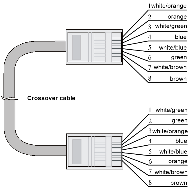
Pin assignments
Select an Ethernet twisted pair cable according to the RJ-45 Ethernet port type on your device. An RJ-45 Ethernet port can be MDI (for routers and PCs) or MDIX (for switches). For the pinouts of RJ-45 Ethernet ports, see Table5-4 and Table5-5.
Table5-4 RJ-45 MDI port pinouts
|
10BASE-T/100BASE-TX |
1000BASE-T |
|||
|
Signal |
Function |
Signal |
Function |
|
|
1 |
Tx+ |
Send data |
BIDA+ |
Bi-directional data cable A+ |
|
2 |
Tx- |
Send data |
BIDA- |
Bi-directional data cable A- |
|
3 |
Rx+ |
Receive data |
BIDB+ |
Bi-directional data cable B+ |
|
4 |
Reserved |
— |
BIDC+ |
Bi-directional data cable C+ |
|
5 |
Reserved |
— |
BIDC- |
Bi-directional data cable C |
|
6 |
Rx- |
Receive data |
BIDB- |
Bi-directional data cable B- |
|
7 |
Reserved |
— |
BIDD+ |
Bi-directional data cable D+ |
|
8 |
Reserved |
— |
BIDD- |
Bi-directional data cable D- |
Table5-5 RJ-45 MDI-X port pinouts
|
Pin |
10BASE-T/100BASE-TX |
1000BASE-T |
||
|
Signal |
Function |
Signal |
Function |
|
|
1 |
Rx+ |
Receive data |
BIDB+ |
Bi-directional data cable B+ |
|
2 |
Rx- |
Receive data |
BIDB- |
Bi-directional data cable B- |
|
3 |
Tx+ |
Send data |
BIDA+ |
Bi-directional data cable A+ |
|
4 |
Reserved |
— |
BIDD+ |
Bi-directional data cable D+ |
|
5 |
Reserved |
— |
BIDD- |
Bi-directional data cable D- |
|
6 |
Tx- |
Send data |
BIDA- |
Bi-directional data cable A- |
|
7 |
Reserved |
— |
BIDC+ |
Bi-directional data cable C+ |
|
8 |
Reserved |
— |
BIDC- |
Bi-directional data cable C- |
To ensure normal communication, the pins for sending data on one port should correspond to the pins for receiving data on the peer port. When both of the ports on the two devices are MDI or MDIX, a crossover Ethernet cable is needed. A cross-over cable connects devices of the same type. When one port is MDI and the other is MDIX, a straight-through Ethernet cable is needed. A straight-through cable connects devices of different types.
If an RJ-45 Ethernet port with MDI/MDIX autosensing enabled can automatically negotiate pin roles. The RJ-45 Ethernet ports on the switch support MDI/MDIX. By default, MDI/MDIX is enabled on a port.
Making an Ethernet twisted pair cable
1. Cut the cable to length with the crimping pliers.
2. Strip off an appropriate length of the cable sheath. The length is typically that of the RJ-45 connector.
3. Untwist the pairs so that they can lie flat, and arrange the colored wires based on the wiring specifications.
4. Cut the top of the wires even with one another. Insert the wires into the RJ-45 end and make sure the wires extend to the front of the RJ-45 end and make good contact with the metal contacts in the RJ-45 end and in the correct order.
5. Crimp the RJ-45 connector with the crimping plier until you hear a click.
6. Repeat the above steps with the other end of the cable.
7. Use a cable tester to verify the connectivity of the cable.
Optical fiber
|
|
CAUTION: Use the same types of transceiver modules, pigtail cords, patch cords, and fiber cables. If you use single-mode optical fibers, the transceiver modules, pigtail cords, patch cords, and fiber cables must be single-mode. |
Optical fiber
Optical fibers are widely used in fiber-optic communications, which are advantageous for long-distance communications.
Optical fibers can be classified into the following types:
· Single mode fiber—It has a core size of 10 µm, and has a lower modal dispersion. It carries only a single ray of light. It is mostly used for communication over longer distances.
· Multi-mode fiber—It has a core size of 50 µm or 62.5 µm or higher, and has a higher modal dispersion than single-mode optical fiber. It is mostly used for communication over shorter distances.
Table5-6 Allowed maximum tensile force and crush load
|
Period of force |
Tensile load (N) |
Crush load (N/mm) |
|
Short period |
150 |
500 |
|
Long term |
80 |
100 |
Fiber cable
A fiber cable is a cable containing one or more optical fibers. The optical fiber elements are typically individually coated with plastic layers and contained in a protective tube. Fiber cables fall into single-mode and multi-mode.
Patch cord
A fiber that has connectors at both ends is called a patch cord. A patch cord connects one optical device to another for signal routing. Patch cords fall into single-mode and multi-mode patch cords.
· Single-mode patch cord—The jacket is yellow. It permits transmission over longer distances.
· Multi-mode patch cord—The jacket is orange. It permits transmission over shorter distances.
The length of a patch cord can be 0.5 m (1.64 ft), 1 m (3.28 ft), 2 m (6.56 ft), 3 m (9.84 ft), 5 m (16.40 ft), and 10 m (32.81 ft).
Pigtail cord
A pigtail cord is an optical fiber that has an optical connector on one end and a length of exposed fiber on the other. The end of the pigtail is fusion spliced to a fiber, connecting the fiber cable and transceiver.
Pigtail cords fall into single-mode (yellow) and multi-mode (orange).
Fiber connector
Fiber connectors are indispensable passive components in an optical fiber communication system. They allow the removable connection between optical channels, which makes the optical system debugging and maintenance more convenient and the transit dispatching of the system more flexible. Figure5-4 shows an LC connector. For more information about fiber connectors, see H3C Transceiver Modules User Guide.

SFP+ DAC cable
You can use SFP+ DAC cables to connect SFP+ ports. SFP+ DAC cables support the SFP+ standard and use 10-GE SFP+ Cu standard cables.
Figure5-5 SFP+ DAC cable

|
(1) Connector |
(2) Pull latch |
SFP28 DAC cable
You can use SFP28 DAC cables to connect SFP28 ports.
Figure5-6 SFP28 DAC cable
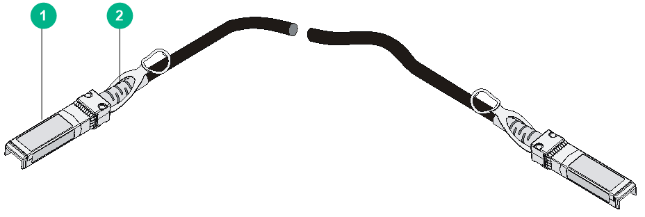
|
(1) Connector |
(2) Pull latch |
SFP28 AOC cable
You can use SFP28 AOC cables to connect SFP28 ports.
Figure5-7 SFP28 AOC cable

|
(1) Connector |
(2) Pull latch |
QSFP+ DAC cable
You can use QSFP+ DAC cables to connect QSFP+ ports.
Figure5-8 QSFP+ DAC cable

|
(1) Connector |
(2) Pull latch |
QSFP+ AOC cable
You can use QSFP+ AOC cables to connect QSFP+ ports.
Figure5-9 QSFP+ AOC cable
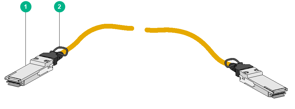
|
(1) Connector |
(2) Pull latch |
QSFP28 DAC cable
You can use QSFP28 DAC cables to connect QSFP28 ports.
Figure5-10 QSFP28 DAC cable
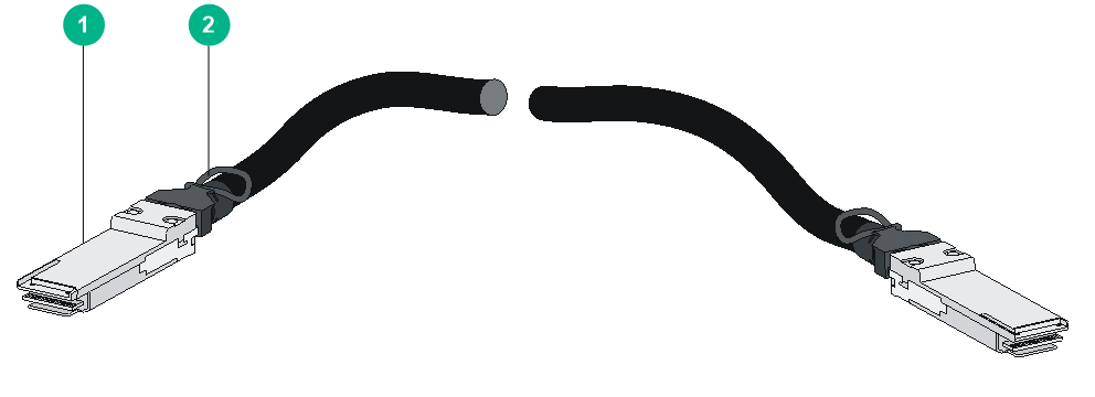
|
(1) Connector |
(2) Pull latch |
QSFP28 AOC cable
You can use QSFP28 AOC cables to connect QSFP28 ports.
Figure5-11 QSFP28 AOC cable

|
(1) Connector |
(2) Pull latch |
QSFP+ to SFP+ DAC cable
A QSFP+ to SFP+ DAC cable provides one QSFP+ connector at one end and four SFP+ connectors at the other end.
Figure5-12 QSFP+ to SFP+ DAC cable
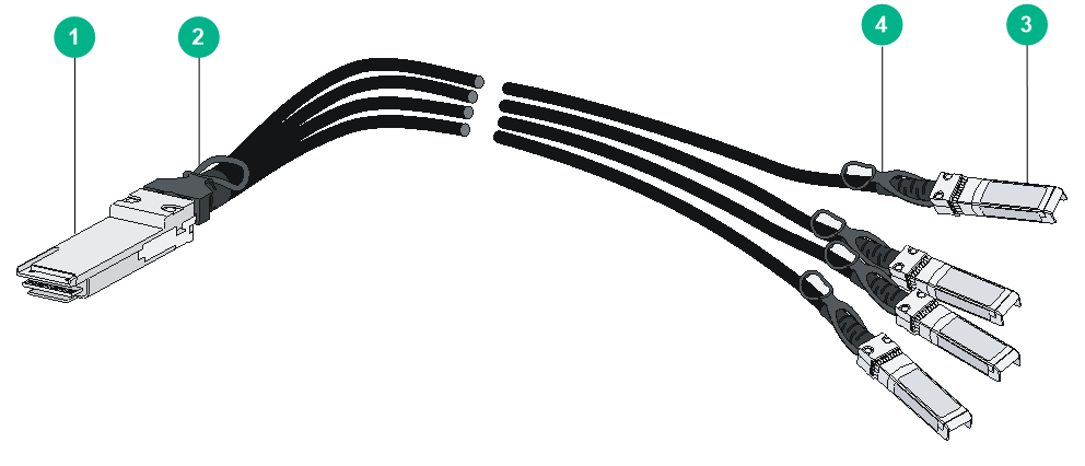
|
(1) QSFP+ connector |
(2) QSFP+ pull latch |
|
(3) SFP+ connector |
(4) SFP+ pull latch |
QSFP28 to SFP28 DAC cable
A QSFP28 to SFP28 DAC cable provides one QSFP28 connector at one end and four SFP28 connectors at the other end.
Figure5-13 QSFP28 to SFP28 DAC cable
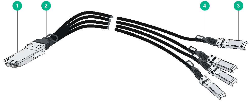
|
(1) QSFP28 connector |
(2) QSFP28 pull latch |
|
(3) SFP28 connector |
(4) SFP28 pull latch |
