- Table of Contents
- Related Documents
-
| Title | Size | Download |
|---|---|---|
| 01-Installation Guide | 964.74 KB |
Examining the installation environment
Examining the installation site
Checking power distribution or power supply environment
Installing the switch in a 19-inch rack
Mounting the switch on a workbench
Grounding the switch by using a grounding strip
Verifying the connection after grounding the switch
Preparing for installation
This document is applicable to the S1600V2 switch series. Table 1 describes the S1600V2 switch series models.
|
Product series |
Product codes |
Product models |
|
|
S1600V2 series |
Non-PoE models |
LS-1600V2-6P-GL |
S1600V2-6P |
|
LS-1600V2-10P-GL |
S1600V2-10P |
||
|
LS-1600V2-18P-GL |
S1600V2-18P |
||
|
LS-1600V2-26P-GL |
S1600V2-26P |
||
|
LS-1600V2-26S-GL |
S1600V2-26S |
||
|
PoE models |
LS-1600V2-6P-HPWR-GL |
S1600V2-6P-HPWR |
|
|
LS-1600V2-10P-HPWR-GL |
S1600V2-10P-HPWR |
||
|
LS-1600V2-18P-HPWR-GL |
S1600V2-18P-HPWR |
||
|
LS-1600V2-26P-HPWR-GL |
S1600V2-26P-HPWR |
||
|
LS-1600V2-26S-HPWR-GL |
S1600V2-26S-HPWR |
||
|
|
NOTE: · For product selection and purchasing, see the switch datasheet at: https://www.h3c.com/en/Products_and_Solutions/InterConnect/Switches/. · For the compatibility between the product models and software versions, see the release notes. |
Safety recommendations
|
|
CAUTION: Only qualified professionals can install and remove the device and its attachments. Before installation and operation, carefully read the provided security instructions. |
To avoid possible environmental pollution and bodily injury, read the following safety precautions before installing the device. Note that the precautions do not cover every possible hazardous condition.
· Before cleaning the switch, remove all power cords from the switch. Do not clean the switch with wet cloth or liquid.
· Do not place the switch near water or in a damp environment. Prevent water or moisture from entering the switch chassis.
· Do not place the switch on an unstable case or desk.
· Ensure good ventilation at the installation site and keep the air inlet and outlet vents of the switch free of obstruction.
· Make sure the power source voltage meets the requirements of the switch.
· To avoid electrical shocks, do not open the chassis while the switch is operating. As a best practice, do not open the chassis even if the switch is powered off.
Examining the installation environment
Before installing this switch series, check if the environment meets the requirements to ensure that the switch operates properly. For information about site check items, see Table 2.
Table 2 Checking list for the installation environment
|
Item |
Requirements |
|
Ventilation and heat dissipation |
Ensure a minimum clearance of 10 cm (3.94 in) around the chassis.
To ensure correct operation of your device, make sure the installation environment is adequately ventilated to prevent the switch from overheating. · Do not install the device near a heat source, for example, a stove or heater. · Ensure air ventilation in the installation environment. · Do not block the ventilation holes in the device or power adapter. |
|
Anti-moisture |
Do not place the device near water or in a damp environment.
Water or moisture might damage the circuits of the device. · Install the switch in a clean, dry, and ventilated place where temperature is controlled in a stable range. · Make sure the installation environment is free from water leakage or condensation. If required, install a dehumidification device (such as an air conditioner with a dehumidification function or a dedicated dehumidifier). · Do not operate the device under or near the water source, such as the wash basin, laundry room, or areas with high humidity. · Do not touch the device with wet hands. |
|
Hot surface |
Use caution when working near the hot
surface. If the switch has a hot surface sign |
|
Temperature/humidity |
For correct operation and long service
life of your switch, maintain the temperature and humidity in the equipment
room at acceptable ranges. Lasting high relative humidity can cause poor
insulation, electricity leakage, mechanical property change of materials, and
metal corrosion. For the temperature and humidity requirements of the switch, see the hardware information and specifications for the switch. |
|
Lightning protection |
· If a grounding strip is available, make sure the grounding resistance of the device grounding connection to the equipment room's grounding strip must be less than 1 ohm. · If no grounding strip is available and a grounding body (such as an angel iron) is buried into the earth, make sure the grounding resistance of the buried grounding body is less than 10 ohms. Properly ground the switch and check the grounding effectiveness. · Route the signal cables along indoor walls, bury the cables in the earth ground, or thread the cables through steel tubes. Install a signal lightning arrester with a nominal discharge current for a corresponding network interface. · Keep the signal cables far from power cords and lightning rod down conductors. · As a best practice, route power cords indoors. If an AC power cord is routed from outdoors, connect the AC power cord first to a power lightning arrester before leading it to the AC power port on the switch. Make sure the power lightning arrester has a nominal discharge current and the total length of the power cord from the power lighting arrester to the power port on the switch is less than 5 m (16.40 ft). · Ground the switch, rack, independent power supplies, and lightning arresters separately. · You must ground optical fibers with reinforcing metal stiffener from outdoors on an optical distribution frame (ODF) or fiber splice enclosure. |
|
Cable routing |
· Route different types of cables separately. · Keep power cords a minimum of 5 cm (1.97 in) away from other cables.
Do not run an Ethernet cable and power cord in parallel. |
|
ESD prevention |
· Ground the switch correctly. · To avoid ESD damage to the device or components, always wear an ESD wrist strap when you install or remove the device or components. · Make sure the wrist strap has good skin contact and is reliably grounded. |
|
Cleanliness |
For more information, see "Cleanliness." |
|
Corrosive gas prevention |
The installation site must be free from corrosive gases such as acid gases and alkaline gases. For more information, see "Corrosive gas limit." |
|
EMI |
· If AC power is used, use a single-phase three-wire power receptacle with protection earth (PE) to filter interference from the power grid. · Keep the device far away from radio transmitting stations, radar stations, and high-frequency devices. · Use electromagnetic shielding, for example, shielded interface cables, when necessary. |
Cleanliness
Dust buildup on the chassis might cause electrostatic adsorption and dust corrosion, resulting in poor contact of metal connectors and contact points. This might shorten the device's lifetime and even cause device failure in the worst case. Table 3 describes the switch requirement for cleanliness.
Table 3 Switch requirement for cleanliness
|
Substance |
Particle diameter |
Concentration limit |
|
Dust particles |
≥ 0.5 μm |
≤ 1.8 × 10⁷ particles/m3 |
To maintain cleanliness in the equipment room, follow these guidelines:
· Keep the equipment room away from pollution sources. Do not smoke, eat, or drink in the equipment room.
· Use double-layer glass in windows and seal doors and windows with dust-proof rubber strips. Use screen doors and window screens for doors and windows open to the outside and make sure the external windows are air tight.
· Use dustproof materials for floors, walls, and ceilings and use wallpaper or matt paint that does not produce powders.
· Clean the equipment room regularly and clean the air filters of the rack each month.
· Wear ESD clothing and shoe covers before entering the equipment room, keep the ESD clothing and shoe covers clean, and change them frequently.
Corrosive gas limit
Corrosive gases can accelerate corrosion and aging of metal components. Make sure the corrosive gases in the equipment room do not exceed the concentration limits as shown in Table 4.
Table 4 Corrosive gas concentration limits
|
Gas |
Average concentration (mg/m3) |
Maximum concentration (mg/m3) |
|
SO2 |
0.3 |
1.0 |
|
H2S |
0.1 |
0.5 |
|
Cl2 |
0.1 |
0.3 |
|
HCI |
0.1 |
0.5 |
|
HF |
0.01 |
0.03 |
|
NH3 |
1.0 |
3.0 |
|
O3 |
0.05 |
0.1 |
|
NOx |
0.5 |
1.0 |
|
As a best practice, control the corrosive gas concentrations in the equipment room at their average values. Make sure the corrosive gas concentrations do not exceed 30 minutes per day at their maximum values. |
||
To maintain cleanliness in the equipment room, follow these guidelines:
· As a best practice, do not build the equipment room in a place with a high concentration of corrosive gases.
· Make sure the equipment room is not connected to sewer, vertical shaft, or septic tank pipelines and keep it far away from these pipelines. The air inlet of the equipment room must be away from such pollution sources.
· Use environmentally friendly materials to decorate the equipment room. Avoid using organic materials that contains harmful gases, such as sulfur or chlorine-containing insulation cottons, rubber mats, sound-proof cottons, and avoid using plasterboards with high sulfur concentration.
· Place fuel (diesel or gasoline) engines separately. Do not place them in the same equipment room with the device. Make sure the exhausted air of the engines will not flow into the equipment room or towards the air inlet of the air conditioners.
· Place batteries separately. Do not place them in the same room with the device.
· Employ a professional company to monitor and control corrosive gases in the equipment room regularly.
Examining the installation site
Before you install the switch, verify that the installation site meets the installation requirements. The switch can operate correctly in an A1 or A2 installation site. Availability issues might occur if you install the switch in an A3, B1, B2, or C installation site.
|
Category |
Definition |
Example |
|
A1: indoor controlled environment |
· Indoor environments where temperature and humidity are controlled. · Completely enclosed or shielded indoor environments. |
Central equipment rooms, IDC equipment rooms, mobile cabins with air conditioners, outdoor air conditioner cabinets, and heat exchanger cabinets. |
|
A2: indoor partially controlled environment |
· Indoor environments where temperature and humidity are partially controlled. · Incompletely enclosed or shielded places. · Places far from pollution sources. |
Simple equipment rooms, ordinary houses, garages, corridors, and direct ventilation cabinets far from pollution sources, houses without direct exposure to sunlight or rain, railway station platforms, and stadiums. |
|
A3: indoor uncontrolled environment |
· Indoor environments where temperature and humidity are uncontrolled. · Incompletely enclosed or shielded places. · Places near pollution sources. |
Simple equipment rooms, ordinary houses, garages, corridors, and direct ventilation cabinets near pollution sources, houses without direct exposure to sunlight or rain, railway station platforms, stadiums, uncleaned rooms after decoration, and rooms under decoration. |
|
B1: outdoor general environment |
· Unshielded places where the temperature and humidity are not controlled. · Places far from pollution sources. |
Completely exposed outdoor places far from pollution sources. |
|
B2: harsh environment |
· Unshielded places where the temperature and humidity are not controlled. · Sea environments or outdoor land environments near pollution sources. |
Islands, ships, and completely exposed outdoor places near pollution sources. |
|
C: special environments |
Special application environments |
Buried, underwater, or undersea environments and manholes. |
Table 6 Pollution sources
|
Category |
Radius range |
|
Saline water areas such as oceans and saline lakes |
≤ 3.7 km (2.30 miles) |
|
Serious pollution sources such as metallurgic plants, coal mines, and heat and power plants |
≤ 3 km (1.86 miles) |
|
Medium pollution sources such as chemical factories, rubber plants, and electroplating factories |
≤ 2 km (1.24 miles) |
|
Light pollution sources, such as food factories, tanneries, and heating boilers |
≤ 1 km (0.62 miles) |
Checking power distribution or power supply environment
Table 7 Requirements for power distribution or power supply environment
|
Item |
Requirements |
|
Preparation |
The power supply must be available before you install the switch. |
|
Voltage |
The voltage provided to the switch must be within the operating voltage range. For the operating voltage range, see the hardware information and specifications for the switch. |
|
Power receptacle and cables |
· If the external power supply system provides an AC power outlet, use a country-specific AC power cord. Make sure the PE wire of the AC power supply is grounded reliably. · Do not use the power cord provided with the switch on other devices. |
Installation tools
No installation tools are provided with the switch. Prepare the following tools yourself:
· Phillips screwdriver
· Hammer drill
· Rubber hammer
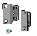
Installation accessories
Before installation, make sure you have all the required installation accessories. If an installation accessory is damaged or lost, purchase a new one by using the BOM code in Table 8.
Table 8 Installation accessories
|
Code |
Description |
Quantity |
Applicable device models |
|
2150A0F4 |
Type A front mounting bracket kit, including a pair of front mounting brackets and four M4 screws
|
1 pair, provided |
S1600V2-18P S1600V2-26P S1600V2-18P-HPWR S1600V2-26P-HPWR |
|
2150A03X |
Type B front mounting bracket kit, including a pair of front mounting brackets and eight M4 screws
|
1 kit, provided |
S1600V2-26S S1600V2-26S-HPWR |
|
N/A |
M6 screw and cage nut
|
User supplied |
S1600V2-18P S1600V2-26P S1600V2-18P-HPWR S1600V2-26P-HPWR |
|
N/A |
Grounding cable
|
1, provided |
S1600V2-18P S1600V2-26P S1600V2-18P-HPWR S1600V2-26P-HPWR |
|
N/A |
Grounding screw
|
1, provided |
S1600V2-18P S1600V2-26P S1600V2-18P-HPWR S1600V2-26P-HPWR |
|
N/A |
AC power cord
The appearance and parameters for power cords vary depending on countries and regions. The power cord in this table is a standard power cord in China. |
1, provided |
S1600V2-18P S1600V2-26P S1600V2-18P-HPWR S1600V2-26P-HPWR |
|
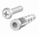
N/A |
Wall anchor kit (expansion anchor and screw)
|
2 pairs, provided |
S1600V2-6P S1600V2-10P S1600V2-6P-HPWR S1600V2-10P-HPWR |


Installing the switch
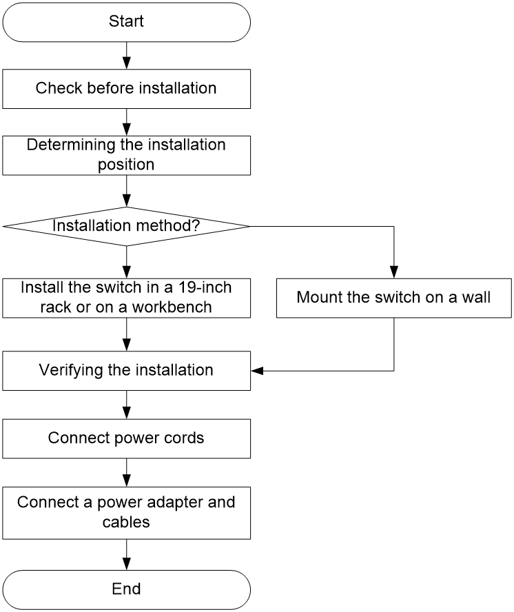
Installation flowchart
Figure 1 Installation flowchart
Installing the device
The H3C S1600V2 series switches are suitable only for indoor installation and the installation methods vary by device model as shown in Table 9.
Table 9 Installation methods for the S1600V2 switch series
|
Product models |
Available installation methods |
Installation procedure |
|
S1600V2-18P S1600V2-26P S1600V2-18P-HPWR S1600V2-26P-HPWR S1600V2-26S S1600V2-26S-HPWR |
Install the switch in a 19-inch rack |
|
|
S1600V2-6P S1600V2-10P S1600V2-6P-HPWR S1600V2-10P-HPWR |
Mount the switch on a wall |
|
|
All models |
Mount the switch on a workbench |
Installing the switch in a 19-inch rack
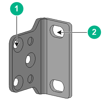
About mounting brackets
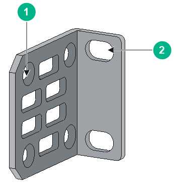
Figure 2 Type A mounting bracket
|
(1) Screw hole for attaching the bracket to the switch |
(2) Screw hole for attaching the bracket to the rack |
Figure 3 Type B mounting bracket
|
(1) Screw hole for attaching the bracket to the switch |
(2) Screw hole for attaching the bracket to the rack |
Attaching the mounting brackets to the switch
|
|
IMPORTANT: M4 screws are used for attaching the mounting brackets to the switch. As a best practice, use a torque of 12 kgf-cm (1.18 Nm) to fasten the M4 screws.. |
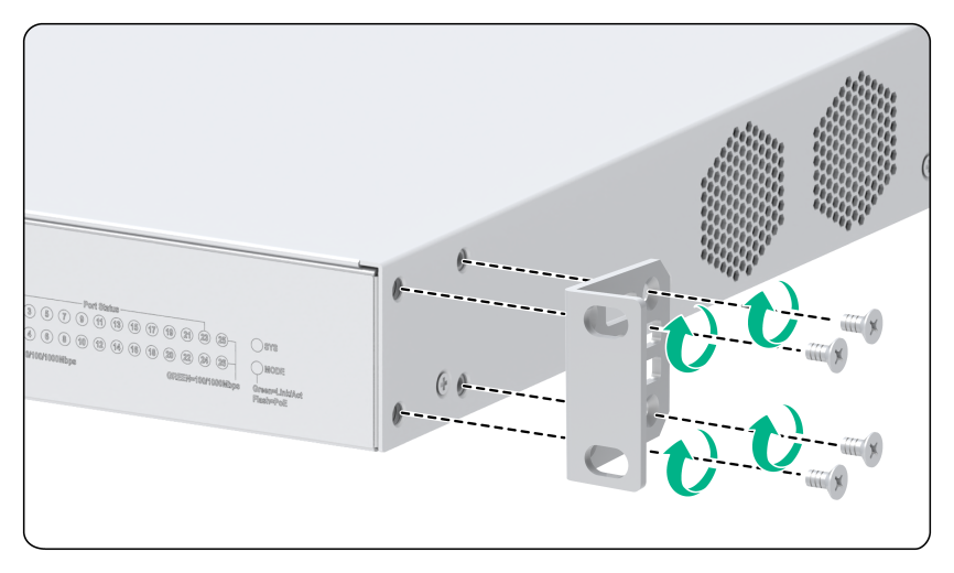
To attach the mounting brackets to the switch:
1. Align the mounting bracket installation holes with the screw holes in the chassis.
2. Fasten the M4 screws (provided) to secure the mounting bracket to the switch, as shown in Figure 5 and Figure 4
|
|
NOTE: The attachment methods for the mounting bracket are similar. This example attaches only one mounting bracket to one side of the switch. |
Figure 4 Attaching the type A mounting brackets to the switch
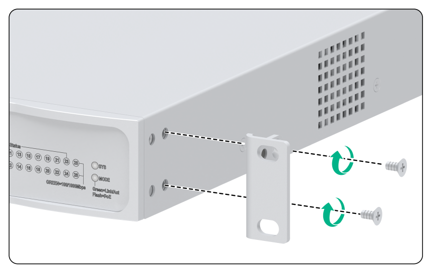
Figure 5 Attaching the type B mounting brackets to the switch
Mounting the switch in the rack
This task requires two people.
To mount the switch in the rack:
1. Wear an ESD wrist strap and make sure it makes good skin contact and is reliably grounded.
2. Verify that the mounting brackets have been securely attached to the switch chassis.
3. Attach cage nuts to the front rack posts.
4. One person supports the bottom of the switch, and moves the switch to an appropriate position based on the installation positions of the mounting brackets.
5. Another person uses user-supplied M6 screws and cage nuts to attach the mounting brackets to the rack and verifies that the brackets are level and secure. As a best practice, use a torque of 30 kgf-cm (2.94 Nm) to fasten the M6 screws.
Figure 6 Rack-mounting the switch (using type A mounting brackets)
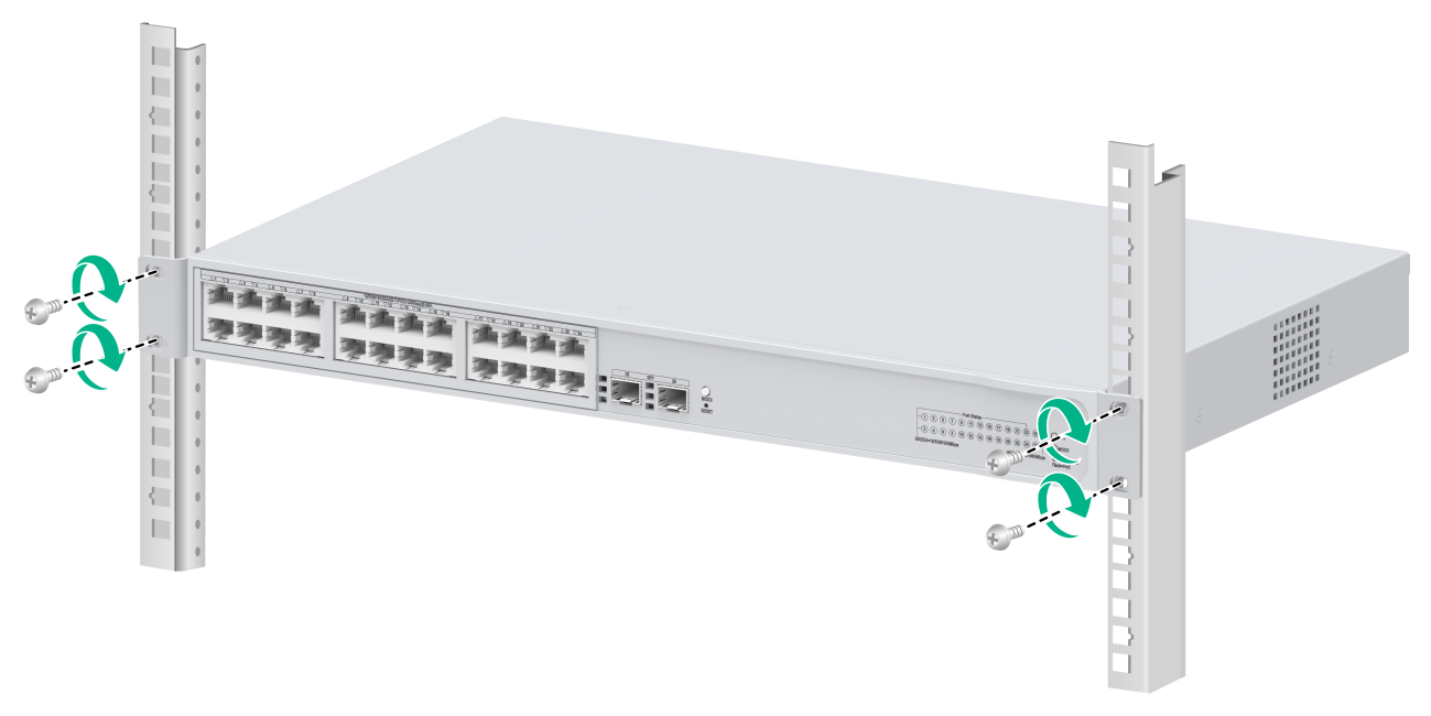
Figure 7 Rack-mounting the switch (using type B mounting brackets)

Mounting the switch on a wall
1. Affix the installation positioning sticker horizontally to the wall with the arrow on it facing downwards.
Figure 8 Installation positioning sticker
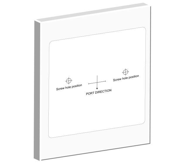
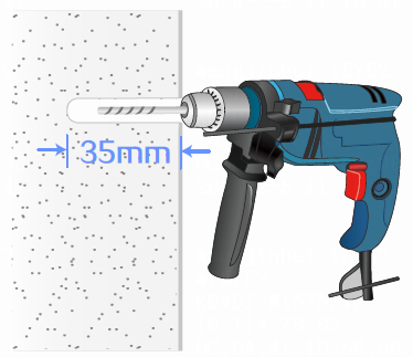
2. Drill two holes with a diameter of 6 mm (0.24 in) and a depth of 35 mm (1.38 in) at the screw hole locations on the positioning sticker, and then remove the positioning sticker.
Figure 9 Drilling holes on the wall
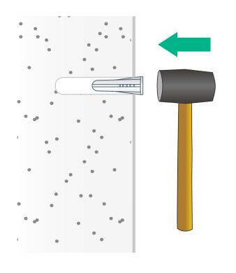
3. Insert a screw anchor into each hole, and tap the screw anchor with a rubber hammer until it is all flush with the wall surface.
Figure 10 Securing the screw anchors
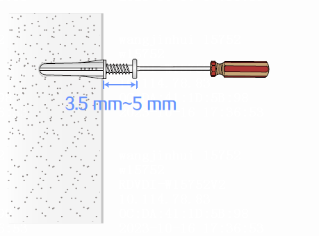
4. Fasten a screw into each screw anchor. Leave 3.5 to 5 mm (0.14 to 0.20 in) between the screw head and the wall for hanging the switch.
Figure 11 Fastening a screw into a screw anchor
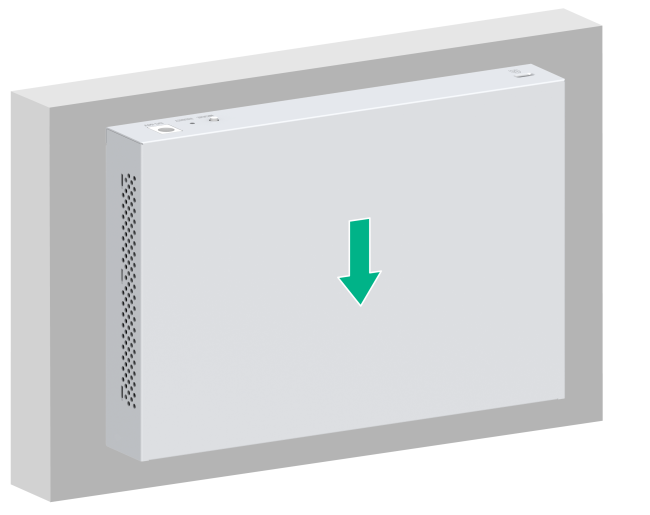
5. Align the installation holes in the switch with the screws on the wall. Make sure the port side faces downwards. Hang the switch on the screws and slide the switch down until the screws seat securely in the installation holes.
Figure 12 Wall-mounting the switch (1)
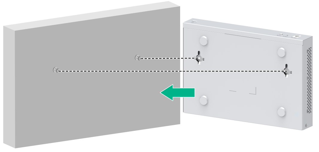
Figure 13 Wall-mounting the switch (2)
Mounting the switch on a workbench
If you do not have a 19-inch standard rack or do not need to mount a switch on a wall. In this case, you can mount the switch on a clean workbench, which is a simple operation.
1. Place the switch with bottom up, and clean the round holes in the chassis bottom with dry cloth.
2. Attach the rubber feet to the four round holes in the chassis bottom. This step is required for a switch model with the rubber feet.
3. Attach the rubber feet to the four round holes in the chassis bottom.
4. Place the switch with upside up on the workbench.
Follow these restrictions and guidelines during operation:
· Keep the workbench stable.
· Reserve a minimum clearance of 10 cm (3.94 in) around the chassis for heat dissipation.
· Do not place heavy objects on the switch.
Grounding the switch
|
|
NOTE: This task is required only for the models that come with a grounding cable. |
|
|
WARNING! · Correctly connecting the grounding cable is crucial to lightning protection and ESD and EMI protection. You must connect the grounding cable correctly and reliably for the switch. · For information about lightning protection for the switch, see H3C Network Devices Lightning Protection Guide. |
To ensure correct operation of electrical devices and personal safety, you must ground electrical devices reliably. Use a grounding cable to connect the device to the earthing facility at the installation site.
Reliable grounding of devices brings the following benefits:
· Protects human body from electric shocks.
· Protects devices and power and data lines from damages.
· Prevents electrical fires, lightning strokes, electromagnetic coupling interferences, ESD damages, and ensures correct operation of the power system.
Select a grounding method based on the installation environment.
|
|
NOTE: The power and grounding terminals in this section are for illustration only. |
Grounding the switch by using a grounding strip
|
|
CAUTION: · Connect the grounding cable to the grounding strip in the equipment room. Do not connect it to a fire main or lightning rod. · To guarantee the grounding effect and avoid switch damage, use the grounding cable provided with the switch to connect the switch to a grounding strip in the equipment room. |
If a grounding strip is available at the installation site, use the grounding cable provided with the switch to connect the switch to the grounding strip.
Connecting the grounding cable to the chassis
1. Remove the grounding screw in the rear panel of the chassis.
2. Use the grounding screw to attach the ring terminal of the grounding cable to the grounding screw hole. Fasten the screw. As a best practice, use a torque of 16 kgf-cm (1.57 Nm) to fasten the grounding screw.
|
|
IMPORTANT: Orient the grounding cable as shown in Figure 14 so that you can easily install or remove the expansion cards. |
Figure 14 Connecting the grounding cable to the chassis

|
(1) Grounding screw |
(2) Ring terminal |
|
(3) Grounding sign |
(4) Grounding hole |
|
(5) Grounding cable |
|
Connecting the grounding cable to a grounding strip
1. Use needle-nose pliers to bend the bare metal part to the shape as shown in Figure 15. Make sure the bended part can securely attached to the grounding post on the grounding strip.
2. Attach the bended part of the grounding cable to the grounding post and use the hex nut to fasten the bended part to the post.
Figure 15 Connecting the grounding cable to a grounding strip
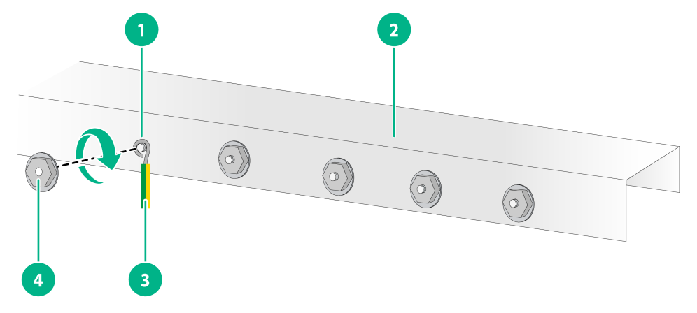
|
(1) Grounding post |
(2) Grounding strip |
|
(3) Grounding cable |
(4) Hex nut |
Verifying the connection after grounding the switch
· If you ground the switch by using a grounding strip, perform the following tasks:
a. Use a multimeter to measure the resistance between the switch grounding terminal and grounding point, and make sure the resistance is less than 0.1 ohms.
b. Use a grounding resistance tester to measure the grounding resistance of the grounding strip, and make sure the grounding resistance is less than 1 ohm.
· If you ground the switch by using a grounding conductor buried in the earth ground, perform the following tasks:
a. Use a multimeter to measure the resistance between the switch grounding terminal and grounding point, and make sure the resistance is less than 0.1 ohms.
b. Use a grounding resistance tester to measure the grounding resistance of the angle iron in the ground, and make sure the grounding resistance is less than 10 ohms. For locations with high soil resistivity, sprinkle some resistance reducer to reduce soil resistivity or replace soil around the grounding strip with soil with lower resistance.
For information about resistance measurement, see H3C Network Devices Lightning Protection Guide.
Connecting power cords
|
CAUTION: · Provide a circuit breaker for each power cord. · Before connecting the power cord, make sure the circuit breaker on the power cord is turned off. |
Table 10 displays the power supply methods supported by the switch.
Table 10 Power supply methods supported by the switch
|
Power supply method |
Switch model |
Power cord connection procedure |
|
Local power supply (using an AC power cord) |
S1600V2-18P S1600V2-26P S1600V2-26S S1600V2-18P-HPWR S1600V2-26S-HPWR S1600V2-26P-HPWR |
|
|
Local power supply (using a power adapter) |
S1600V2-6P S1600V2-6P-HPWR S1600V2-10P S1600V2-10P-HPWR |
Connecting the AC power cord
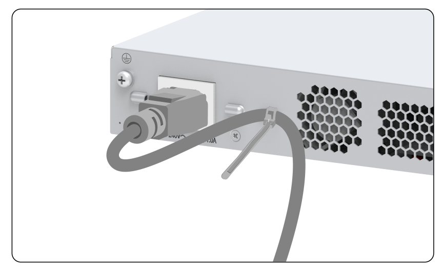
1. Connect the female connector of the AC power cord to the AC-input power receptacle on the switch, as shown in Figure 16.
2. Use a cable tie to secure the power cord to the handle near the AC-input power receptacle, as shown in Figure 17.
3. Connect the other end of the AC power cord to an AC power source.
Figure 16 Connecting the AC power cord (1)
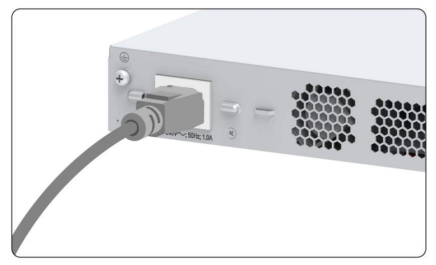
Figure 17 Connecting the AC power cord (2)
Connect a power adapter
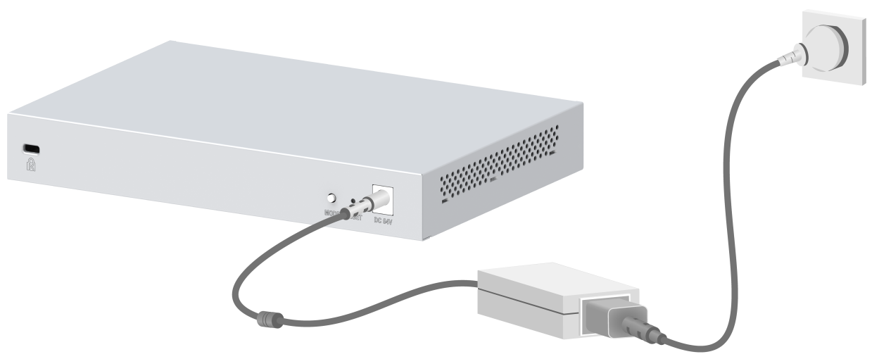
|
|
NOTE: The figure in this section is for your reference only. The power adapter appearance varies by country or region. |
The switch supports the following types of power adapters and the supported power adapter varies by switch model:
· Type-1 power adapter: A type-1 power adapter can meet the power supply requirements.
· Type-2 power adapter: A type-2 power adapter must be connected to an AC power cord to supply power.
To connecting a power adapter:
1. Connect the power adapter to an AC power cord. (This step is only applicable to a type-2 power adapter.)
2. Insert the circular plug of the power adapter into the power adapter receptacle on the switch.
3. Connect the other end of the power adapter to an external AC power source.
Figure 18 Connecting a type-1 power adapter

Figure 19 Connecting a type-2 power adapter
Verifying the installation
After you complete the installation, verify the following information:
· There is enough space around the switch for heat
dissipation.
The rack or workbench is stable.
· The grounding cable is connected correctly.
· The power source is as required by the switch.
· The power cords are correctly connected.
· If part of the network cable for a port is routed outdoors, verify that a network port lightning protector is used for the port. If a power line is routed from outdoors, verify that a surge protected power strip is used for the switch.
Check after power-on
Examine the LEDs on the switch after you power on the switch to verify that the switch is operating correctly.
