- Table of Contents
- Related Documents
-
| Title | Size | Download |
|---|---|---|
| 01-Hardware Information and Specifications | 1.17 MB |
Product models and technical specifications
10/100/1000BASE-T Ethernet port
10/100/1000BASE-T auto-sensing Ethernet port LEDs
Product models and technical specifications
Product models
|
Product series |
Product codes |
Product models |
|
|
S1600V2 series |
Non-PoE models |
LS-1600V2-6P-GL |
S1600V2-6P |
|
LS-1600V2-10P-GL |
S1600V2-10P |
||
|
LS-1600V2-18P-GL |
S1600V2-18P |
||
|
LS-1600V2-26P-GL |
S1600V2-26P |
||
|
LS-1600V2-26S-GL |
S1600V2-26S |
||
|
PoE models |
LS-1600V2-6P-HPWR-GL |
S1600V2-6P-HPWR |
|
|
LS-1600V2-10P-HPWR-GL |
S1600V2-10P-HPWR |
||
|
LS-1600V2-18P-HPWR-GL |
S1600V2-18P-HPWR |
||
|
LS-1600V2-26P-HPWR-GL |
S1600V2-26P-HPWR |
||
|
LS-1600V2-26S-HPWR-GL |
S1600V2-26S-HPWR |
||
|
|
NOTE: · For product selection and purchasing, see the switch datasheet at: https://www.h3c.com/en/Products_and_Solutions/InterConnect/Switches/. · For the compatibility between the product models and software versions, see the release notes. |
Technical specifications
Non-PoE switch models
Table 2 Product specifications (non-PoE models)
|
Item |
S1600V2-6P |
S1600V2-10P |
S1600V2-18P |
S1600V2-26P |
|
Physical specifications |
||||
|
Dimensions (H × W × D) |
27 × 130 × 124 mm (1.06 × 5.12 × 4.88 in) |
27 × 185 × 125 mm (1.06 × 7.28 × 4.92 in) |
44 × 440 × 160 mm (1.73 × 17.32 × 6.30 in) |
44 × 440 × 160 mm (1.73 × 17.32 × 6.30 in) |
|
Dimensions (including packaging) (H × W × D) |
61 × 239 × 161 mm (2.40 × 9.41 × 6.34 in) |
55 × 239 × 186 mm (2.17 × 9.41× 9.32 in) |
106 × 525 × 302 mm (4.17 × 20.67 × 11.89 in) |
106 × 525 × 302 mm (4.17 × 20.67 × 11.89 in) |
|
Weight |
≤ 0.6 kg (1.32 lb) |
≤ 0.6 kg (1.32 lb) |
≤ 2.1 kg (4.63 lb) |
≤ 2.2 kg (4.85 lb) |
|
Technical specifications |
||||
|
Memory (RAM) |
N/A |
N/A |
N/A |
N/A |
|
Flash |
4 MB |
4 MB |
4 MB |
4 MB |
|
Interface type and quantity |
|
|||
|
10/100/1000BASE-T auto-sensing Ethernet port |
5 |
9 |
16 |
24 |
|
SFP |
1 |
1 |
2 |
2 |
|
Power supply specifications |
||||
|
Power input |
Adapter input |
AC input |
||
|
Power supply specifications |
· Rated voltage range: 100V to 240V AC, 50/60Hz · Maximum voltage range: 90V to 264V AC, 47 to 63Hz |
· Rated voltage range: 100V to 240V AC, 50/60Hz · Maximum voltage range: 90V to 264V AC, 47 to 63Hz |
||
|
Overall system power consumption |
||||
|
Power consumption (static) Collection standard: No load |
2 W |
3 W |
3.5 W |
4.3 W |
|
Power consumption (typical) Collection standard: Fully configured with power cables or network cables, 30% load |
4 W |
5 W |
9.9 W |
13.6 W |
|
Power consumption (full load) Collection standard: fully configured with transceiver modules or network cables, 100% load |
4 W |
6 W |
11.2 W |
16 W |
|
System thermal consumption |
||||
|
Thermal consumption (static) Collection standard: No load |
6.9 BTU/h |
10.3 BTU/h |
12 BTU/h |
15 BTU/h |
|
Thermal consumption (typical) Collection standard: Fully configured with power cables or network cables, 30% load |
13.7 BTU/h |
17.1 BTU/h |
34 BTU/h |
47 BTU/h |
|
Thermal consumption (full load) Collection standard: fully configured with transceiver modules or network cables, 100% load |
13.7 BTU/h |
20.5 BTU/h |
39 BTU/h |
55 BTU/h |
|
Heat dissipation |
||||
|
Cooling method |
Fanless, passive cooling |
|||
|
Reliability and availability |
||||
|
Mean time between failure (MTBF) (year) |
114.0041 |
100.7564 |
84.3551 |
84.3551 |
|
Mean time to repair (MTTR) (hour) |
1 |
|||
|
Availability |
99.9998999% |
99.9998867% |
99.9998647% |
99.9998647% |
|
Environment specifications |
||||
|
Operating temperature |
–5°C to +45°C (23°F to 113°F) NOTE: The maximum acceptable temperature decreases by 0.33°C (32.59°F) for every 100 m (328.08 ft) increase in altitude from 0 m (0 ft). |
|||
|
Storage temperature |
–40°C to +70°C (–40°F to +158°F) |
|||
|
Relative humidity |
5% RH to 95% RH, noncondensing |
|||
|
Compliance |
||||
|
Product compliance |
· Safety standards · EMC standards · Environmental and eco-friendly standards |
|||
|
Product lightning protection |
||||
|
Connector lightning protection |
N/A |
N/A |
6 KV |
6 KV |
|
Power lightning protection |
N/A |
N/A |
6 KV |
6 KV |
|
Item |
S1600V2-26S |
|
Physical specifications |
|
|
Dimensions (H × W × D) |
43.6 × 440 × 160 mm (1.72 × 17.32 × 6.30 in) |
|
Dimensions (including packaging) (H × W × D) |
106 × 525 × 296 mm (4.17 × 20.67 × 11.65 in) |
|
Weight |
≤ 2.5 kg (5.51 lb) |
|
Technical specifications |
|
|
Memory (RAM) |
128 MB |
|
Flash |
16 MB |
|
Interface type and quantity |
|
|
10/100/1000BASE-T autosensing Ethernet ports |
24 |
|
SFP+ ports |
2 |
|
Power supply specifications |
|
|
Power input type |
AC input |
|
Power supply specifications |
· Rated voltage range: 100 VAC to 240 VAC @ 50/60 Hz · Max voltage range: 90 VAC to 264 VAC @ 47 to 63 Hz |
|
Melting current of power supply fuse |
10A/250V |
|
Overall system power consumption |
|
|
Power consumption (static) Collection standard: No load |
8 W |
|
Power consumption (typical) Collection standard: Fully configured with power cables or network cables, 30% load |
18 W |
|
Power consumption (full load) Collection standard: fully configured with transceiver modules or network cables, 100% load |
22 W |
|
Thermal consumption |
|
|
Thermal consumption (static) Collection standard: No load |
27 BTU/h |
|
Thermal consumption (typical) Collection standard: Fully configured with power cables or network cables, 30% load |
61 BTU/h |
|
Thermal consumption (full load) Collection standard: fully configured with transceiver modules or network cables, 100% load |
75 BTU/h |
|
Heat dissipation |
|
|
Cooling method |
Fanless, passive cooling |
|
Reliability and availability |
|
|
Mean time between failure (MTBF) (year) |
59.2 |
|
Mean time to repair (MTTR) (hour) |
1 |
|
Availability |
99.9998072% |
|
Environment specifications |
|
|
Altitude |
–60 to +5000 m (–196.85 to +16404.20 ft) |
|
Operating temperature |
–5°C to +45°C (23°F to 113°F) NOTE: The maximum acceptable temperature decreases by 0.33°C (32.59°F) for every 100 m (328.08 ft) increase in altitude from 0 m (0 ft). |
|
Storage temperature |
–40°C to +70°C (–40°F to +158°F) |
|
Relative humidity |
5% RH to 95% RH, noncondensing |
|
Compliance |
|
|
Product compliance |
· Safety standards · EMC standards · Environmental and eco-friendly standards |
|
Product lightning protection |
|
|
Connector lightning protection |
6 KV |
|
Power lightning protection |
6 KV |
PoE switch models
Table 3 Product specifications (PoE models) (1)
|
Item |
S1600V2-6P-HPWR |
S1600V2-10P-HPWR |
|
Physical specifications |
||
|
Dimensions (H × W × D) |
27 × 130 × 124 mm (1.06 × 5.12 × 4.88 in) |
27 × 185 × 125 mm (1.06 × 7.28 × 4.92 in) |
|
Dimensions (including packaging) (H × W × D) |
73 × 228 × 222 mm (2.87 × 8.98 × 8.74 in) |
76 × 243 × 245 mm (2.99 × 9.57× 9.65 in) |
|
Weight |
≤ 0.5 kg (1.32 lb) |
≤ 0.6 kg (1.32 lb) |
|
Technical specifications |
||
|
Memory (RAM) |
N/A |
N/A |
|
Flash |
4 MB |
4 MB |
|
Interface type and quantity |
||
|
10/100/1000BASE-T auto-sensing Ethernet port |
5 NOTE: Ports 1 to 4 support PoE. |
9 NOTE: Ports 1 to 8 support PoE. |
|
SFP port |
1 |
1 |
|
Power supply specifications |
||
|
Power input |
Adapter input terminal |
|
|
Power supply specifications |
· Rated voltage range: 100V to 240V AC, 50/60Hz · Maximum voltage range: 90V to 264V AC, 47 to 63Hz |
|
|
PoE power capacity |
||
|
Maximum PoE power per port |
30 W |
30 W |
|
Total PoE power |
73 W |
125 W |
|
System power consumption |
||
|
Power consumption (static) Collection standard: No load |
3 W |
4 W |
|
Power consumption (typical) Collection standard: Fully configured with power cables or network cables, 30% load |
5 W |
6 W |
|
Power consumption (full load) Collection standard: fully configured with transceiver modules or network cables, 100% load |
86 W |
132W |
|
System thermal consumption |
||
|
Thermal consumption (static) Collection standard: No load |
10.3 BTU/h |
13.7 BTU/h |
|
Thermal consumption (typical) Collection standard: Fully configured with power cables or network cables, 30% load |
17.1 BTU/h |
20.5 BTU/h |
|
Thermal consumption (full load) Collection standard: fully configured with transceiver modules or network cables, 100% load |
294.3 BTU/h |
450.2 BTU/h |
|
Heat dissipation |
||
|
Cooling method |
Fanless, passive cooling |
|
|
Reliability and availability |
||
|
Mean time between failure (MTBF) (year) |
88.59625 |
78.47745 |
|
Mean time to repair (MTTR) (hour) |
1 |
|
|
Availability |
99.9998712% |
99.9998545% |
|
Environment specifications |
||
|
Operating temperature |
–5°C to +45°C (23°F to 113°F) NOTE: The maximum acceptable temperature decreases by 0.33°C (32.59°F) for every 100 m (328.08 ft) increase in altitude from 0 m (0 ft). |
|
|
Storage temperature |
–40°C to +70°C (–40°F to +158°F) |
|
|
Relative humidity |
5% RH to 95% RH, noncondensing |
|
|
Compliance |
||
|
Product compliance |
· Safety standards · EMC standards · Environmental and eco-friendly standards |
|
|
Product lightning protectionA |
||
|
Connector lightning protection |
N/A |
|
|
Power lightning protection |
N/A |
|
Table 4 Product specifications (PoE models) (2)
|
Item |
S1600V2-18P-HPWR |
S1600V2-26P-HPWR |
|
Physical specifications |
||
|
Dimensions (H × W × D) |
44 × 440 × 260 mm (1.73 × 17.32 × 10.24 in) |
44 × 440 × 260 mm (1.73 × 17.32 × 10.24 in) |
|
Dimensions (including packaging) (H × W × D) |
145 × 538 × 404 mm (5.71 × 21.18 × 15.91 in) |
145 × 538 × 404 mm (5.71 × 21.18 × 15.91 in) |
|
Weight |
≤ 3.5 kg (7.72 lb) |
≤ 3.7 kg (8.16 lb) |
|
Technical specifications |
||
|
Memory (RAM) |
N/A |
N/A |
|
Flash |
4 MB |
4 MB |
|
Interface type and quantity |
||
|
10/100/1000BASE-T auto-sensing Ethernet port |
16 |
24 |
|
SFP port |
2 |
2 |
|
Power supply specifications |
||
|
Power input |
AC power input |
|
|
Power supply specifications |
· Rated voltage range: 100V to 240V AC, 50/60Hz · Maximum voltage range: 90V to 264V AC, 47 to 63Hz |
|
|
Melting current of power supply fuse |
8 A/250 V |
10 A/250 V |
|
PoE power capacity |
||
|
Maximum PoE power per port |
35 W |
35 W |
|
Total PoE power |
240 W |
370 W |
|
Overall system power consumption |
||
|
Power consumption (static) Collection standard: No load |
8.2 W |
10.6 W |
|
Power consumption (typical) Collection standard: Fully configured with power cables or network cables, 30% load |
15 W |
20.5 W |
|
Power consumption (full load) Collection standard: fully configured with transceiver modules or network cables, 100% load |
279.3 W |
439.2 W |
|
System thermal consumption |
||
|
Thermal consumption (static) Collection standard: No load |
28 BTU/h |
37 BTU/h |
|
Thermal consumption (typical) Collection standard: Fully configured with power cables or network cables, 30% load |
52 BTU/h |
70 BTU/h |
|
Thermal consumption (full load) Collection standard: fully configured with transceiver modules or network cables, 100% load |
954 BTU/h |
1499 BTU/h |
|
Heat dissipation |
||
|
Cooling method |
Air-cooled heat dissipation |
|
|
Heat dissipation air duct |
Left-and-right air duct |
|
|
Reliability and availability |
||
|
Mean time between failure (MTBF) (year) |
79.35 |
88.24763 |
|
Mean time to repair (MTTR) (hour) |
1 |
|
|
Availability |
99.99998% |
99.99998% |
|
Environment specifications |
||
|
Operating temperature |
–5°C to +45°C (23°F to 113°F) NOTE: The maximum acceptable temperature decreases by 0.33°C (32.59°F) for every 100 m (328.08 ft) increase in altitude from 0 m (0 ft). |
|
|
Storage temperature |
–40°C to +70°C (–40°F to +158°F) |
|
|
Relative humidity |
5% RH to 95% RH, noncondensing |
|
|
Compliance |
||
|
Product compliance |
· Safety standards · EMC standards · Environmental and eco-friendly standards |
|
|
Product lightning protection |
||
|
Connector lightning protection |
6 KV |
6 KV |
|
Power lightning protection |
6 KV |
6 KV |
|
Item |
S1600V2-26S-HPWR |
|
Physical specifications |
|
|
Dimensions (H × W × D) |
43.6 × 440 × 260 mm (1.72 × 17.32 × 10.24 in) |
|
Dimensions (including packaging) (H × W × D) |
135 × 558 × 384 mm (5.32 × 21.97 × 15.12 in) |
|
Weight |
≤ 3.8 kg (8.38 lb) |
|
Technical specifications |
|
|
Memory (RAM) |
128 MB |
|
Flash |
16 MB |
|
Interface type and quantity |
|
|
10/100/1000BASE-T autosensing Ethernet ports |
24 |
|
SFP+ ports |
2 |
|
Power supply specifications |
|
|
Power input type |
AC input |
|
Power supply specifications |
· Rated voltage range: 100 VAC to 240 VAC @ 50/60 Hz · Max voltage range: 90 VAC to 264 VAC @ 47 to 63 Hz |
|
Melting current of power supply fuse |
10A/250V |
|
Overall system power consumption |
|
|
Power consumption (static) Collection standard: No load |
13 W |
|
Power consumption (typical) Collection standard: Fully configured with power cables or network cables, 30% load |
24 W |
|
Power consumption (full load) Collection standard: fully configured with transceiver modules or network cables, 100% load |
447 W |
|
Thermal consumption |
|
|
Thermal consumption (static) Collection standard: No load |
44 BTU/h |
|
Thermal consumption (typical) Collection standard: Fully configured with power cables or network cables, 30% load |
82 BTU/h |
|
Thermal consumption (full load) Collection standard: fully configured with transceiver modules or network cables, 100% load |
1628 BTU/h |
|
PoE power supply capability |
|
|
Max PoE power per port |
35 W |
|
Total PoE power |
400 W |
|
Heat dissipation |
|
|
Heat dissipation method |
Fixed fans |
|
Ventilation aisles |
Left-to-right |
|
Reliability and availability |
|
|
Mean time between failure (MTBF) (year) |
48.3 |
|
Mean time to repair (MTTR) (hour) |
1 |
|
Availability |
99.9997635% |
|
Environment specifications |
|
|
Altitude |
–60 to +5000 m (–196.85 to +16404.20 ft) |
|
Operating temperature |
–5°C to +45°C (23°F to 113°F) NOTE: The maximum acceptable temperature decreases by 0.33°C (32.59°F) for every 100 m (328.08 ft) increase in altitude from 0 m (0 ft). |
|
Storage temperature |
–40°C to +70°C (–40°F to +158°F) |
|
Relative humidity |
5% RH to 95% RH, noncondensing |
|
Compliance |
|
|
Product compliance |
· Safety standards · EMC standards · Environmental and eco-friendly standards |
|
Product lightning protection |
|
|
Connector lightning protection |
6 KV |
|
Power lightning protection |
6 KV |
Chassis views
S1600V2-6P switch
Figure 1 S1600V2-6P front panel
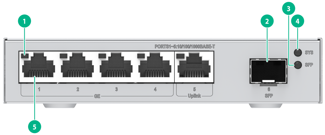
|
(1) 10/100/1000BASE-T autosensing Ethernet port LED |
(2) SFP port |
|
(3) SFP port LED |
(4) System status LED (SYS) |
|
(5) 10/100/1000BASE-T auto-sensing Ethernet port |
|
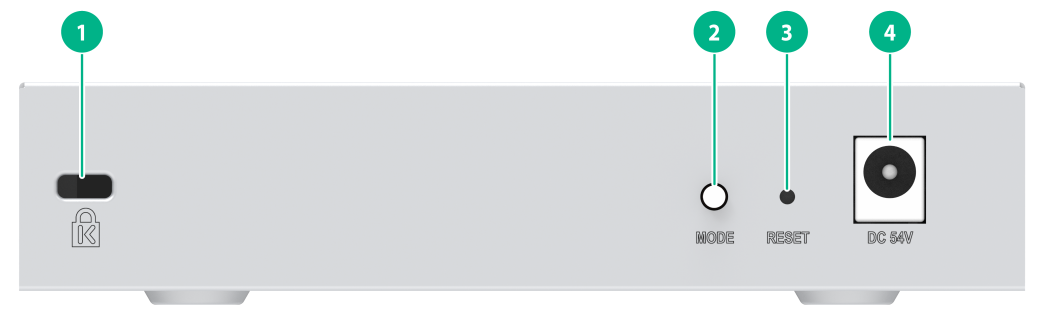
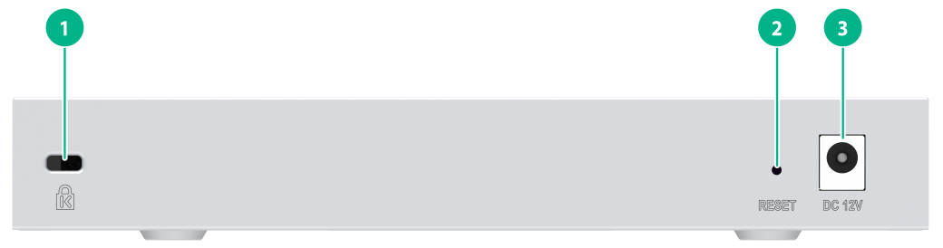
Figure 2 S1600V2-6P rear panel

|
(1) Anti-theft lock |
(2) RESET button |
|
(3) Adapter input terminal |
|
|
|
NOTE: Use the RESET button as follows: · Hold down the button for less than one second. When the SYS LED stays solid green, release the button, and the device will restart. · Hold down the button for one to five seconds until the SYS LED flashes red slowly (1 Hz). Release the key, and the device will restore the default Web login password. · Hold down button for five to 10 seconds until the SYS LED flashes red rapidly (8 Hz). Release the button, and the device will restore to the factory defaults and restart. · Hold down the button for more than 10 seconds. Release the button when the SYS LED restores to steady green; the device will not perform any restoration actions. |
S1600V2-6P-HPWR switch
Figure 3 S1600V2-6P-HPWR front panel
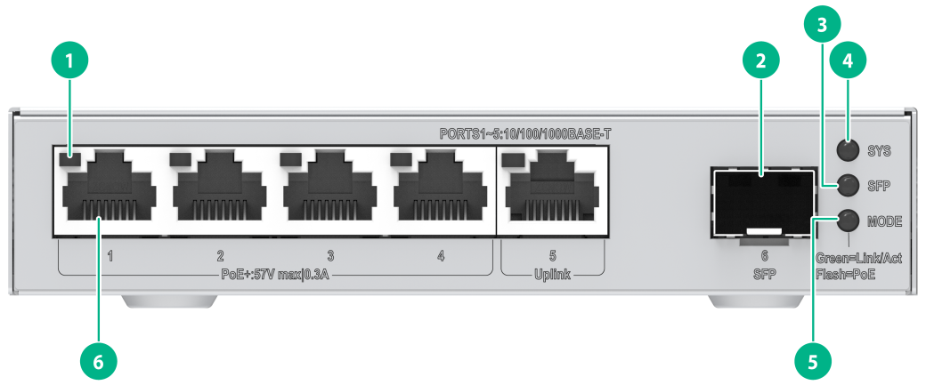
|
(1) 10/100/1000BASE-T autosensing Ethernet port LED |
(2) SFP port |
|
(3) SFP port LED |
(4) System status LED (SYS) |
|
(5) Mode LED (MODE) |
(6) 10/100/1000BASE-T autosensing Ethernet port |
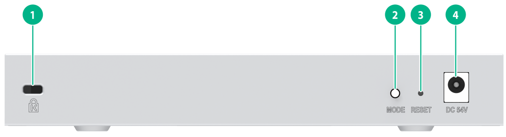
Figure 4 S1600V2-6P-HPWR rear panel
|
(1) Anti-theft lock |
(2) Mode LED (MODE) |
|
(3) RESET button |
(4) Adapter input terminal |
|
|
NOTE: Use the RESET button as follows: · Hold down the button for less than one second. When the SYS LED stays solid green, release the button, and the device will restart. · Hold down the button for one to five seconds until the SYS LED flashes red slowly (1 Hz). Release the key, and the device will restore the default Web login password. · Hold down button for five to 10 seconds until the SYS LED flashes red rapidly (8 Hz). Release the button, and the device will restore to the factory defaults and restart. · Hold down the button for more than 10 seconds. Release the button when the SYS LED restores to steady green; the device will not perform any restoration actions. |
S1600V2-10P switch
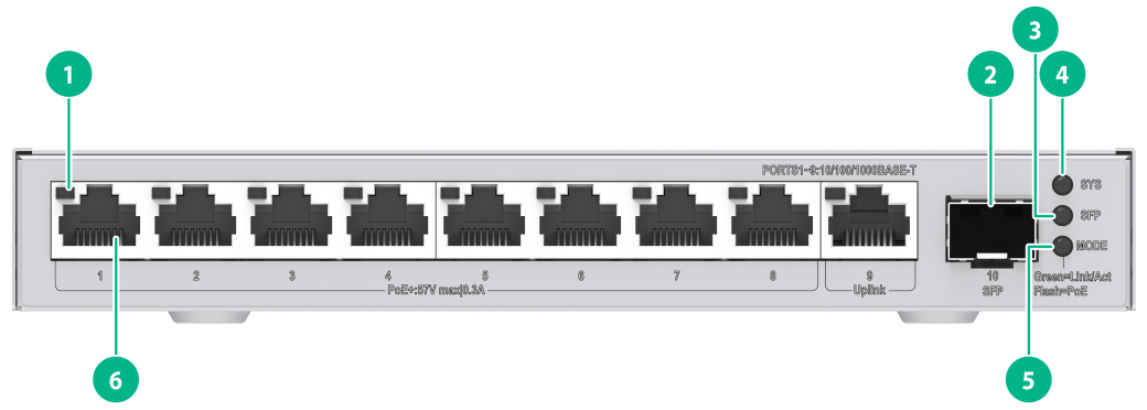
Figure 5 S1600V2-10P front panel
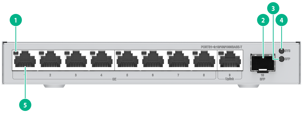
|
(1) 10/100/1000BASE-T autosensing Ethernet port LED |
(2) SFP port |
|
(3) SFP port LED |
(4) System status LED (SYS) |
|
(5) 10/100/1000BASE-T auto-sensing Ethernet port |
|
Figure 6 S1600V2-10P rear panel
|
(1) Anti-theft lock |
(2) RESET button |
|
(3) Adapter input terminal |
|
|
|
NOTE: Use the RESET button as follows: · Hold down the button for less than one second. When the SYS LED stays solid green, release the button, and the device will restart. · Hold down the button for one to five seconds until the SYS LED flashes red slowly (1 Hz). Release the key, and the device will restore the default Web login password. · Hold down button for five to 10 seconds until the SYS LED flashes red rapidly (8 Hz). Release the button, and the device will restore to the factory defaults and restart. · Hold down the button for more than 10 seconds. Release the button when the SYS LED restores to steady green; the device will not perform any restoration actions. |
S1600V2-10P-HPWR
Figure 7 Front Panel Diagram of S1600V2-10P-HPWR
|
(1) 10/100/1000BASE-T autosensing Ethernet port LED |
(2) SFP port |
|
(3) SFP port LED |
(4) System status LED (SYS) |
|
(5) Mode LED (MODE) |
(6) 10/100/1000BASE-T auto-sensing Ethernet port |
Figure 8 S1600V2-10P-HPWR front panel
|
(1) Anti-theft lock |
(2) Mode LED (MODE) |
|
(3) RESET button |
(4) Adapter input terminal |
|
|
NOTE: Use the RESET button as follows: · Hold down the button for less than one second. When the SYS LED stays solid green, release the button, and the device will restart. · Hold down the button for one to five seconds until the SYS LED flashes red slowly (1 Hz). Release the key, and the device will restore the default Web login password. · Hold down button for five to 10 seconds until the SYS LED flashes red rapidly (8 Hz). Release the button, and the device will restore to the factory defaults and restart. · Hold down the button for more than 10 seconds. Release the button when the SYS LED restores to steady green; the device will not perform any restoration actions. |
S1600V2-18P switch
Figure 9 S1600V2-18P front panel
|
(1) 10/100/1000BASE-T auto-sensing Ethernet port |
(2) SFP port |
|
(3) RESET button |
(4) 10/100/1000BASE-T auto-sensing Ethernet port LED |
|
(5) SFP port LED |
(6) System status LED (SYS) |
|
|
NOTE: Use the RESET button as follows: · Hold down the button for less than one second. When the SYS LED stays solid green, release the button, and the device will restart. · Hold down the button for one to five seconds until the SYS LED flashes red slowly (1 Hz). Release the key, and the device will restore the default Web login password. · Hold down button for five to 10 seconds until the SYS LED flashes red rapidly (8 Hz). Release the button, and the device will restore to the factory defaults and restart. · Hold down the button for more than 10 seconds. Release the button when the SYS LED restores to steady green; the device will not perform any restoration actions. |
Figure 10 S1600V2-18P rear panel
|
(1) Grounding screw |
(2) AC-input power receptacle |
S1600V2-18P-HPWR switch
Figure 11 S1600V2-18P-HPWR front panel
|
(1) 10/100/1000BASE-T auto-sensing Ethernet port |
(2) SFP port |
|
(3) Mode LED (MODE) |
(4) RESET button |
|
(5) 10/100/1000BASE-T auto-sensing Ethernet port LED |
(6) SFP port LED |
|
(7) System status LED (SYS) |
(8) Mode switch button for the port mode LED |
|
|
NOTE: Use the RESET button as follows: · Hold down the button for less than one second. When the SYS LED stays solid green, release the button, and the device will restart. · Hold down the button for one to five seconds until the SYS LED flashes red slowly (1 Hz). Release the key, and the device will restore the default Web login password. · Hold down button for five to 10 seconds until the SYS LED flashes red rapidly (8 Hz). Release the button, and the device will restore to the factory defaults and restart. · Hold down the button for more than 10 seconds. Release the button when the SYS LED restores to steady green; the device will not perform any restoration actions. |
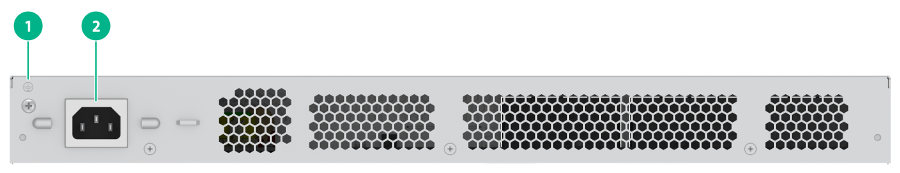
Figure 12 S1600V2-18P-HPWR rear panel
|
(1) Grounding screw |
(2) AC-input power receptacle |
S1600V2-26P switch
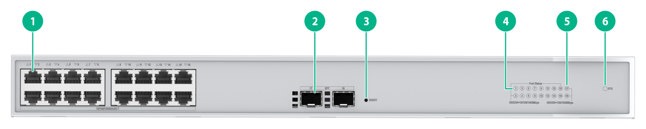
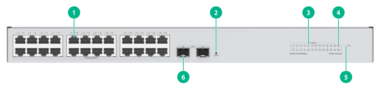
Figure 13 S1600V2-26P front panel
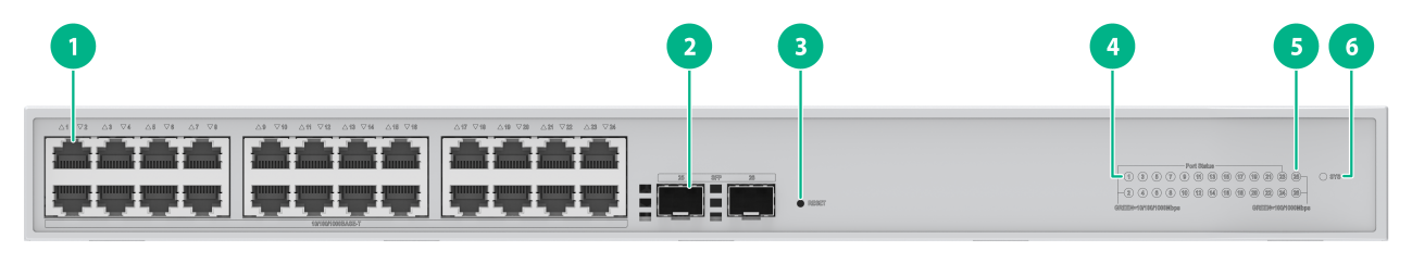
|
(1) 10/100/1000BASE-T auto-sensing Ethernet port |
(2) SFP port |
|
(3) RESET button |
(4) 10/100/1000BASE-T auto-sensing Ethernet port LED |
|
(5) SFP port LED |
(6) System status LED (SYS) |
|
|
NOTE: Use the RESET button as follows: · Hold down the button for less than one second. When the SYS LED stays solid green, release the button, and the device will restart. · Hold down the button for one to five seconds until the SYS LED flashes red slowly (1 Hz). Release the key, and the device will restore the default Web login password. · Hold down button for five to 10 seconds until the SYS LED flashes red rapidly (8 Hz). Release the button, and the device will restore to the factory defaults and restart. · Hold down the button for more than 10 seconds. Release the button when the SYS LED restores to steady green; the device will not perform any restoration actions. |
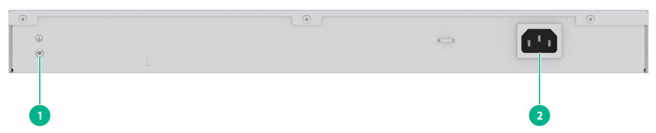
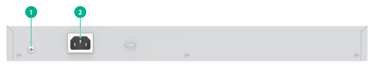
Figure 14 S1600V2-26P rear panel
|
(1) Grounding screw |
(2) AC-input power receptacle |
S1600V2-26P-HPWR switch
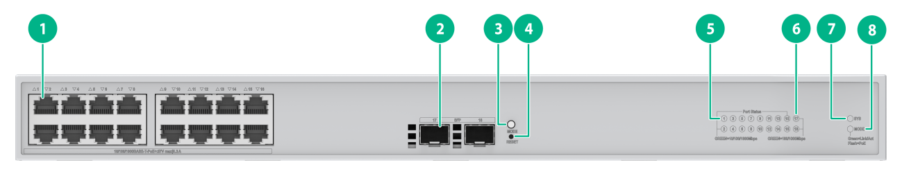
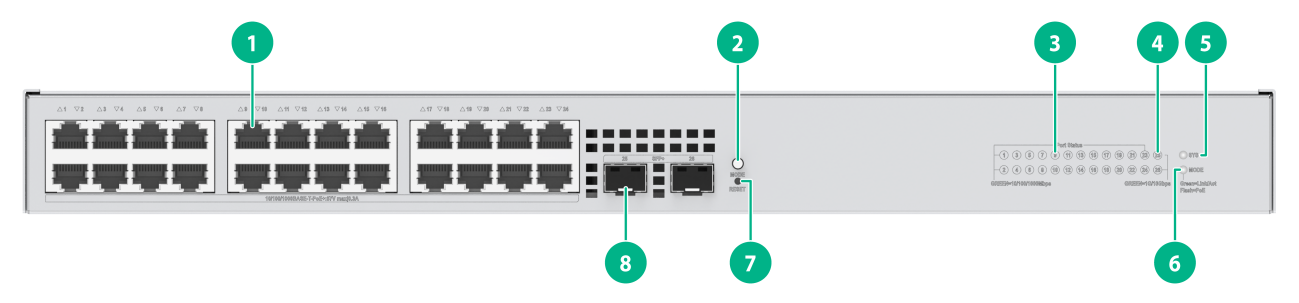
Figure 15 S1600V2-26P-HPWR front panel
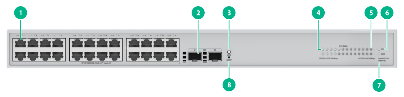
|
(1) 10/100/1000BASE-T auto-sensing Ethernet port |
(2) SFP port |
|
(3) Mode switch button for the port mode LED |
(4) 10/100/1000BASE-T auto-sensing Ethernet port LED |
|
(5) SFP port LED |
(6) System status LED (SYS) |
|
(7) Mode LED (MODE) |
(8) RESET button |
|
|
NOTE: Use the RESET button as follows: · Hold down the button for less than one second. When the SYS LED stays solid green, release the button, and the device will restart. · Hold down the button for one to five seconds until the SYS LED flashes red slowly (1 Hz). Release the key, and the device will restore the default Web login password. · Hold down button for five to 10 seconds until the SYS LED flashes red rapidly (8 Hz). Release the button, and the device will restore to the factory defaults and restart. · Hold down the button for more than 10 seconds. Release the button when the SYS LED restores to steady green; the device will not perform any restoration actions. |
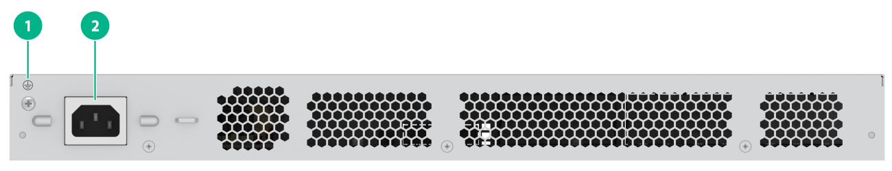
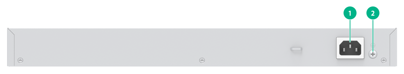
Figure 16 S1600V2-26P-HPWR rear panel

|
(1) Grounding screw |
(2) AC-input power receptacle |
S1600V2-26S
Figure 17 S1600V2-26S front panel
|
(1) 10/100/1000BASE-T autosensing Ethernet port |
(2) RESET button |
|
(3) 10/100/1000BASE-T autosensing Ethernet port LED |
(4) SFP+ port LED |
|
(5) System LED (SYS) |
(6) SFP+ port |
|
|
NOTE: The methods for using the RESET button are as follows: · To restart the device, press the button and release the button when the SYS LED turns steady green. · To restore the default Web login password, press and hold the button for 1 to 5 seconds and release the button when the SYS LED flashes red slowly (1 Hz). · To restore the factory default and restart the device, press and hold the button for 5 to 10 seconds and release the button when the SYS LED flashes red rapidly (8 Hz). · If you press and hold the button for over 10 seconds and release the button when the SYS LED turns steady green, no action is performed. |
Figure 18 S1600V2-26S rear panel
|
(1) Grounding screw |
(2) AC power receptacle |
S1600V2-26S-HPWR
Figure 19 S1600V2-26S-HPWR front panel
|
(1) 10/100/1000BASE-T autosensing Ethernet port |
(2) Switch button for the port mode LED |
|
(3) 10/100/1000BASE-T autosensing Ethernet port LED |
(4) SFP+ port LED |
|
(5) System LED (SYS) |
(6) Port mode LED (MODE) |
|
(7) RESET button |
(8) SFP+ port |
|
|
NOTE: The methods for using the RESET button are as follows: · To restart the device, press the button and release the button when the SYS LED turns steady green. · To restore the default Web login password, press and hold the button for 1 to 5 seconds and release the button when the SYS LED flashes red slowly (1 Hz). · To restore the factory default and restart the device, press and hold the button for 5 to 10 seconds and release the button when the SYS LED flashes red rapidly (8 Hz). · If you press and hold the button for over 10 seconds and release the button when the SYS LED turns steady green, no action is performed. |
Figure 20 S1600V2-26S-HPWR rear panel
|
(1) AC power receptacle |
(2) Grounding screw |
Ports and LEDs
Ports
10/100/1000BASE-T Ethernet port
Table 5 10/100/1000BASE-T Ethernet port attributes
|
Item |
Description |
|
Connector type |
RJ-45 |
|
Rate and duplex mode |
· 10Mbit/s full duplex/half duplex · 100Mbit/s full duplex/half duplex · 1000Mbit/s full duplex · MDI/MDI-X, auto-sensing |
|
Max transmission distance |
100 m (328.08 ft) |
|
Transmission medium |
Category 5 and above twisted pair cable |
|
Compliant standard |
IEEE 802.3i, 802.3u, 802.3ab |
|
Supported models |
All switch models |
SFP ports
Table 6 SFP port attributes (1)
|
Item |
Description |
|
Interface type |
SFP ports |
|
Rate and duplex mode |
Supports all GE SFP transceiver modules and cables described in Table 9. |
|
Supported models |
S1600V2-10P and S1600V2-10P-HPWR |
Table 7 SFP port attributes (2)
|
Item |
Description |
|
Interface type |
SFP |
|
Rate and duplex mode |
Supports GE SFP transceiver modules and cables described in Table 9. Supports all 2.5G SFP transceiver modules Table 11. |
|
Supported models |
S1600V2-6P and S1600V2-6P-HPWR |
|
Restrictions and guidelines |
In versions earlier than R8811, SFP port supports speed switching between 1 Gbps and 2.5 Gbps. For the change to take effect, switch the port speed on the Web interface and restart the device. In R8811 and later versions, SFP port is speed-autosensing. After you change the transceiver module to a 1G or 2.5G one for a port, the device automatically restarts for speed autosensing. |
Table 8 SFP port attributes (3)
|
Item |
Description |
|
Interface type |
SFP |
|
Rate and duplex mode |
Supports all GE SFP transceiver modules and cables described in Table 10. |
|
Supported models |
S1600V2-18P, S1600V2-26P, S1600V2-18P-HPWR, and S1600V2-26P-HPWR |
Table 9 GE SFP transceiver modules and cables (1)
|
Transceiver module/cable model |
Transceiver module/cable model |
Central wavelength |
Connector type |
Interface cable specifications |
Modal bandwidth (MHz*km) |
Max transmission distance |
|
|
SFP module |
SFP-GE-SX-MM850-A |
850 nm |
LC |
50/125 µm, MMF |
500 |
550 m (1804.46 ft) |
|
|
400 |
500 m (1640.42 ft) |
||||||
|
62.5/125 µm, MMF |
200 |
275 m (902.23 ft) |
|||||
|
160 |
200 m (656.17 ft) |
||||||
|
160 |
200 m (656.17 ft) |
||||||
|
SFP-GE-LX-SM1310-A |
1310 nm |
LC |
9/125 µm, SMF |
N/A |
10 km (32808.40 ft) |
||
|
50/125 µm, MMF |
500/400 |
550 m (1804.46 ft) |
|||||
|
62.5/125 µm, MMF |
500 |
550 m (1804.46 ft) |
|||||
|
SFP-GE-LX-SM1310-BIDI |
Note: The modules of these two models must be used in pairs. |
RX: 1310 nm RX: 1490 nm |
LC |
9/125 µm, SMF |
N/A |
10 km (32808.40 ft) |
|
|
SFP-GE-LX-SM1490-BIDI |
TX: 1490 nm RX: 1310 nm |
N/A |
|||||
|
SFP-GE-LX-SM1310-BIDI-I |
Note: The modules of these two models must be used in pairs. |
RX: 1310 nm RX: 1490 nm |
LC |
9/125 µm, SMF |
N/A |
10 km (32808.40 ft) |
|
|
SFP-GE-LX-SM1490-BIDI-I |
TX: 1490 nm RX: 1310 nm |
N/A |
|||||
|
SFP cables |
SFP-STACK-Kit |
N/A |
N/A |
SFP cables |
N/A |
1.5 m (32808.40 ft) |
|
Table 10 GE SFP transceiver modules and cables (2)
|
Transceiver module/cable model |
Transceiver module/cable model |
Central wavelength |
Connector type |
Interface cable specifications |
Modal bandwidth (MHz*km) |
Max transmission distance |
||
|
SFP copper transceiver module |
SFP-GE-T |
N/A |
RJ-45 |
Twisted pair |
N/A |
100 m (328.08 ft) |
||
|
SFP-GE-T-D |
N/A |
RJ-45 |
Twisted pair |
N/A |
100 m (328.08 ft) |
|||
|
All-optical 3.0 dedicated transceiver module |
SFP-GE-LX-SM1310-F |
1310 nm |
PoDLC |
Hybrid copper-fiber cable |
N/A |
10 km (32808.40 ft) |
||
|
SFP module |
SFP-GE-SX-MM850-A |
850 nm |
LC |
50/125 µm, MMF |
500 |
550 m (1804.46 ft) |
||
|
400 |
500 m |
|||||||
|
62.5/125 µm, MMF |
200 |
275 m (902.23 ft) |
||||||
|
160 |
200 m (656.17 ft) |
|||||||
|
160 |
200 m (656.17 ft) |
|||||||
|
SFP-GE-LX-SM1310-A |
1310 nm |
LC |
9/125 µm, SMF |
N/A |
10 km (32808.40 ft) |
|||
|
50/125 µm, MMF |
500/400 |
550 m (1804.46 ft) |
||||||
|
62.5/125 µm, MMF |
500 |
550 m (1804.46 ft) |
||||||
|
SFP-GE-LX-SM1310-BIDI |
Note: The modules of these two models must be used in pairs. |
TX: 1310 nm RX: 1490 nm |
LC |
9/125 µm, SMF |
N/A |
10 km (32808.40 ft) |
||
|
SFP-GE-LX-SM1490-BIDI |
TX: 1490 nm RX: 1310 nm |
N/A |
||||||
|
SFP-GE-LX-SM1310-BIDI-I |
Note: The modules of these two models must be used in pairs. |
TX: 1310 nm RX: 1490 nm |
LC |
9/125 µm, SMF |
N/A |
10 km (32808.40 ft) |
||
|
SFP-GE-LX-SM1490-BIDI-I |
TX: 1490 nm RX: 1310 nm |
N/A |
||||||
|
SFP-GE-LX10-SM1310 |
1310 nm |
LC |
9/125 µm, SMF |
N/A |
10 km (32808.40 ft) |
|||
|
SFP cable |
SFP-STACK-Kit |
N/A |
N/A |
SFP cables |
N/A |
1.5 m (4.92 ft) |
||
|
|
NOTE: All-optical 3.0 dedicated transceiver modules supports data transfer and power supply/reception only when they are used with the combined copper-fiber pigtail and hybrid copper-fiber cable. |
Table 11 2.5G SFP transceiver modules
|
Transceiver module/cable model |
Transceiver module/cable model |
Central wavelength |
Connector type |
Interface cable specifications |
Modal bandwidth (MHz*km) |
Max transmission distance |
|
2.5G SFP all-optical 3.0 dedicate transceiver module |
SFP-2.5G-LX10-SM1310-DR-I |
1310 nm |
PoDLC |
Photoelectric hybrid cable |
N/A |
10 km (32808.40 ft) |
|
|
NOTE: · As a best practice, use H3C transceiver modules and cables for the switch. · The H3C transceiver modules and cables are subject to change over time. For the most recent list of H3C transceiver modules and cables, contact your H3C Support or marketing staff. · For more information about H3C transceiver modules and cables, see H3C Transceiver Modules User Guide. |
SFP+ ports
Table 12 SFP+ port specifications (3)
|
Item |
Specification |
|
Port type |
SFP+ ports |
|
Port attributes |
Supports the 10-Gigabit SFP+ transceiver modules and cables listed inTable 13. Supports the Gigabit SFP transceiver modules and cables listed in Table 14. Supports the 2.5G SFP transceiver modules listed in Table 15. |
|
Compatible switch models |
S1600V2-26S S1600V2-26S-HPWR |
Table 13 10-Gigabit SFP+ transceiver modules/cables supported by the SFP+ port (3)
|
Transceiver module/cable type |
Transceiver module/cable name |
Central wavelength |
Connector |
Cable specifications |
Mode bandwidth (MHz*km) |
Maximum transmission distance |
|
SFP+ copper transceiver module |
SFP-10GE-T |
N/A |
RJ-45 |
Category 6e STP or category 7 twisted pair cable |
N/A |
30 m (98.43 ft) |
|
Category 5e twisted pair cable |
N/A |
100 m (328.08 ft) |
||||
|
SFP+ optical transceiver module |
SFP-XG-LH40-SM1550 |
1550 nm |
LC |
9/125 µm, SMF |
N/A |
40 km (24.86 miles) |
|
SFP-XG-LH40-SM1550-D |
1550 nm |
LC |
9/125 µm, SMF |
N/A |
40 km (24.86 miles) |
|
|
SFP-XG-LH40-SM1550-S |
1550 nm |
LC |
9/125 µm, SMF |
N/A |
40 km (24.86 miles) |
|
|
SFP-XG-LX-SM1310-D |
1310 nm |
LC |
9/125 µm, SMF |
N/A |
10 km (6.21 miles) |
|
|
SFP-XG-LX-SM1310 |
1310 nm |
LC |
9/125 µm, SMF |
N/A |
10 km (6.21 miles) |
|
|
SFP-XG-SX-MM850-D |
850 nm |
LC |
50/125 µm, MMF |
4700 |
400 m (1312.34 ft) |
|
|
2000 |
300 m (984.25 ft) |
|||||
|
500 |
82 m (269.03 ft) |
|||||
|
400 |
66 m (216.54 ft) |
|||||
|
62.5/125 µm, MMF |
200 |
33 m (108.27 ft) |
||||
|
160 |
26 m (85.30 ft) |
|||||
|
SFP+ copper cable |
LSWM1STK |
N/A |
N/A |
SFP+ copper cable |
N/A |
0.65 m (2.13 ft) |
|
LSWM2STK |
1.2 m (3.94 ft) |
|||||
|
LSWM3STK |
3 m (9.84 ft) |
|||||
|
LSTM1STK |
5 m (16.40 ft) |
|||||
|
SFP+ fiber cable |
SFP-XG-D-AOC-7M |
N/A |
N/A |
SFP+ fiber cable |
N/A |
7 m (22.97 ft) |
|
SFP-XG-D-AOC-10M |
10 m (32.81 ft) |
|||||
|
SFP-XG-D-AOC-20M |
20 m (65.62 ft) |
H3C provides users with SFP+ cables of different lengths. For more information, see _Ref205870732. For the cable appearance, see Figure 21.
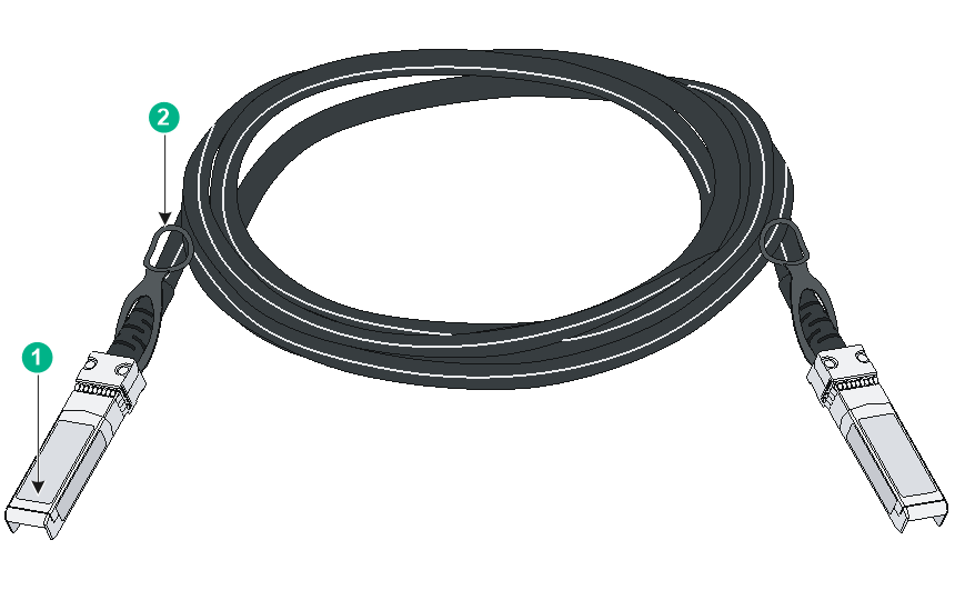
|
(1) Connector |
(2) Latch |
Table 14 GE SFP transceiver modules and cables (4)
|
Transceiver module/cable type |
Transceiver module/cable name |
Central wavelength |
Connector |
Cable specifications |
Mode bandwidth (MHz*km) |
Maximum transmission distance |
|
SFP copper transceiver module |
SFP-GE-T |
N/A |
RJ-45 |
Twisted pair cable |
N/A |
100 m (328.08 ft) |
|
SFP-GE-T-D |
N/A |
RJ-45 |
Twisted pair cable |
N/A |
100 m (328.08 ft) |
|
|
SFP module |
SFP-GE-SX-MM850-A |
850 nm |
LC |
50/125 µm, MMF |
500 |
550 m (1804.46 ft) |
|
400 |
500 m (1640.42 ft) |
|||||
|
62.5/125 µm, MMF |
200 |
275 m (902.23 ft) |
||||
|
160 |
200 m (656.17 ft) |
|||||
|
SFP-GE-SX-MM850-D |
850 nm |
LC |
50/125 µm, MMF |
500 |
550 m (1804.46 ft) |
|
|
400 |
500 m (1640.42 ft) |
|||||
|
62.5/125 µm, MMF |
200 |
275 m (902.23 ft) |
||||
|
160 |
220 m (721.78 ft) |
|||||
|
SFP-GE-LX-SM1310-A |
1310 nm |
LC |
9/125 µm, SMF |
N/A |
10 km (6.21 miles) |
|
|
50/125 µm, MMF |
500/400 |
550 m (1804.46 ft) |
||||
|
62.5/125 µm, MMF |
500 |
550 m (1804.46 ft) |
||||
|
SFP-GE-LX-SM1310-D |
1310 nm |
LC |
9/125 µm, SMF |
N/A |
10 km (6.21 miles) |
|
|
50/125 µm, MMF |
500/400 |
550 m (1804.46 ft) |
||||
|
62.5/125 µm, MMF |
500 |
550 m (1804.46 ft) |
||||
|
SFP-GE-LH40-SM1310 |
1310 nm |
LC |
9/125 µm, SMF |
N/A |
40 km (24.86 miles) |
|
|
SFP-GE-LH40-SM1310-D |
1310 nm |
LC |
9/125 µm, SMF |
N/A |
40 km (24.86 miles) |
|
|
SFP-GE-LH40-SM1550 |
1550 nm |
LC |
9/125 µm, SMF |
N/A |
40 km (24.86 miles) |
|
|
SFP-GE-LX-SM1310-BIDI |
TX: 1310 nm RX: 1490 nm |
LC |
9/125 µm, SMF |
N/A |
10 km (6.21 miles) |
|
|
SFP-GE-LX-SM1490-BIDI |
TX: 1490 nm RX: 1310 nm |
LC |
9/125 µm, SMF |
N/A |
10 km (6.21 miles) |
|
|
SFP-GE-LX-SM1310-BIDI-I |
TX: 1310 nm RX: 1490 nm |
LC |
9/125 µm, SMF |
N/A |
10 km (6.21 miles) |
|
|
SFP-GE-LX-SM1490-BIDI-I |
TX: 1490 nm RX: 1310 nm |
LC |
9/125 µm, SMF |
N/A |
10 km (6.21 miles) |
|
|
SFP cable |
SFP-STACK-Kit |
N/A |
N/A |
SFP cable |
N/A |
1.5 m (4.92 ft) |
|
|
IMPORTANT: Use the following transceiver modules in pairs: · SFP-GE-LX-SM1310-BIDI and SFP-GE-LX-SM1490-BIDI transceiver modules. · SFP-GE-LX-SM1310-BIDI-I and SFP-GE-LX-SM1490-BIDI-I transceiver modules. For example, if one end uses the SFP-GE-LX-SM1310-BIDI transceiver module, the other end must use the SFP-GE-LX-SM1490-BIDI transceiver module. |
Table 15 2.5G SFP transceiver modules (3)
|
Transceiver module/cable type |
Transceiver module/cable name |
Central wavelength |
Connector |
Cable specifications |
Mode bandwidth (MHz*km) |
Maximum transmission distance |
|
2.5G SFP iOptic 3.0 dedicated transceiver module |
SFP-2.5G-LX10-SM1310-DR-I-F |
1310 nm |
PoDLC |
Hybrid copper-fiber cable |
N/A |
10 km (6.21 miles) |
LEDs
System status LED
The system status LED shows the operating status of the switch, as shown in Table 16.
Table 16 System status LED description
|
LED mark |
LED status |
Description |
|
SYS |
Flashing green |
The switch has started up correctly. |
|
Flashing red |
The system is being powered on. |
|
|
Off |
The switch is powered off or has not started up correctly. |
Port mode LED
For models providing a mode switch button for the port mode LED, you can use the button and the port status LEDs to view the port operational status from various angles and obtain more device information.
· The port mode LED informs users about the specific type of information displayed by the port status LEDs for various types of ports.
· You can press the mode switch button for the port mode LED to adjust the display state of the LED, ultimately controlling the information displayed by the port status LEDs.
Table 17 Port mode LED description
|
LED mark |
LED status |
Description |
|
MODE |
Steady green |
The port status LEDs indicate the Link/Active status of ports |
|
Flashing green (only for PoE models) |
The port status LEDs indicate the PoE power supply status of the ports |
10/100/1000BASE-T auto-sensing Ethernet port LEDs
For models providing a mode switch button for the port mode LED, you can use the button and the Ethernet port LEDs to view the port operational status from various angels. For more information, see Table 18.
For models not providing a mode switch button for the port mode LED, see Table 19 to view the Ethernet port LED description.
Table 18 Description for 10/100/1000BASE-T auto-sensing Ethernet port status LED (1)
|
LED status |
Description |
|
|
Port mode LED (MODE) |
Ethernet port LED status |
|
|
Steady green (Link/Active mode) |
Steady green |
A link is present on the port |
|
Flashing green |
The port is receiving or sending data |
|
|
Off |
No link is present on the port. |
|
|
Flashing green (only for PoE models) |
Steady green |
The PoE power supply is normal |
|
Off |
The port is not connected to a PD or PoE is not enabled on the port |
|
Table 19 Description for 10/100/1000BASE-T auto-sensing Ethernet port status LED (2)
|
LED mark |
LED status |
Description |
|
SYS |
Flashing green |
The switch has started up correctly |
|
Steady red |
The system is being powered on |
|
|
Off |
The switch is powered off or has not started up correctly |
SFP port LED description
Table 20 SFP port LED description
|
SFP port LED status |
Description |
|
Steady green |
A link is present on the port. |
|
Flashing green |
The port is receiving or sending data |
|
Off |
· No link is present on the port. · The mode LED is operating in PoE mode (only for PoE models) |