- Table of Contents
- Related Documents
-
| Title | Size | Download |
|---|---|---|
| 02-INT configuration | 202.58 KB |
Contents
Restrictions and guidelines: INT configuration
Enabling global INT packet dropping
Example: Configuring common INT
Example: Configuring flexible INT
Configuring INT
About INT
The Inband Network Telemetry (INT) feature is a network monitoring technology designed to collect data from the device. The device sends data to a collector in real time for device performance monitoring and network monitoring.
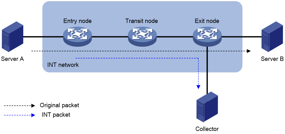
INT network components
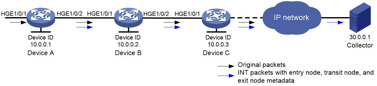
As shown in Figure 1, an INT network contains the following INT-enabled devices: one entry node, one transit node, and one exit node.
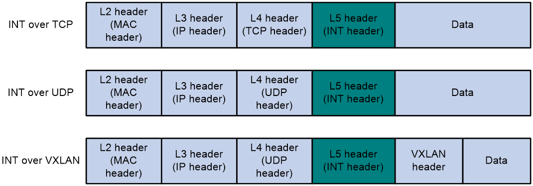
INT packet formats
INT generates INT packets by mirroring original packets, inserting INT headers, and collecting data. The INT header and collected data are in the original IP header. Therefore, an INT packet and its original packet have the same IP header and forwarding path.
The device supports generating INT packets from TCP packets, UDP packets, and VXLAN packets. The protocol number in INT packets is 253.
How INT works
INT supports common INT and flexible INT. The two types of INT have the following differences:
· Common INT—Each node needs to be configured with an INT role on its input interface: ingress, transit, and egress. Traffic flows are defined on the entry node by using a QoS policy. INT flows are automatically identified on the transit node and exit node and processed according to configured actions. On each input interface in the path, you can perform INT processing only on the flows defined on the entry node.
· Flexible INT—No device role needs to be configured on each node. On each node, an ACL can be used to define a flow and an action used to take on the defined flow. For the same flow, the original packets are matched on the entry node, and the INT packets are matched on the transit node and exit node. You can define multiple flows on an interface and take different actions on different flows.
Common INT is easy to configure and is recommended. Use flexible INT only when you need to process multiple flows on an interface.
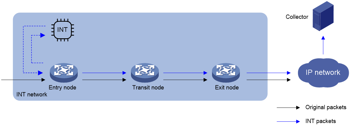
Common INT
As shown in Figure 3, the nodes in common INT perform the following functions:
1. On the entry node, the ingress port uses a QoS policy to sample matching packets, and mirrors sampled packets to the INT processor. Then, the INT processor adds an INT header to the INT packet and loops it back to the ingress port. The ingress port identifies the looped-back INT packet according to the INT mark, adds collected data to it, and forwards it to the egress port. The egress port adds collected data to the INT packet and sends it to the transit node.
2. On the transit node, the ingress port identifies the INT packet according to the INT mark, adds collected data to it, and forwards it to the egress port. The egress port adds collected data to the INT packet, and sends it to the exit node.
3. On the exit node, the ingress port identifies the INT packet according to the INT mark, adds collected data to the INT packet, encapsulates the INT packet with the configured parameters, and sends it to the collector.
Flexible INT
As shown in Figure 3, the nodes in flexible INT perform the following functions:
1. On the entry node, the ingress port uses an ACL to sample matching packets, and mirrors sampled packets to the INT processor. Then, the INT processor adds an INT header to the INT packet and loops it back to the ingress port. The ingress port identifies the looped-back INT packet according to an ACL and adds collected data to it, and forwards it. The egress port adds collected data to the INT packet and sends it to the transit node.
2. On the transit node, the ingress port uses an ACL to identify INT packets, adds collected data to INT packets, and forwards them to the egress port. The egress port adds collected data to INT packets and sends them to the exit node.
3. On the exit node, the ingress port uses an ACL to identify INT packets, encapsulates the INT packets and sends them to the collector.
Figure 3 INT network diagram
Restrictions and guidelines: INT configuration
As a best practice, configure the transit node and exit node before configuring the entry node.
To prevent repeated data sampling, configure only one entry node in an INT network.
The S9825 switch series can only act as a transit node and does not support INT in a VXLAN network.
For an S9825 switch, bit23:21 of the MMU stats field in an INT packet is fixed at 3.
The S9825 and S9855 switch series do not support the queue transmit bytes count field.
The S9825 switch series does not support the egress port speed field.
For an S9825 or S9855 switch, the rx timestamp sec field supports displaying only the device startup time.
In the INT header added on the entry node, the input interface information is padded as 0xFF.
When an S9855 switch acts as an exit node and generates INT packets from VXLAN packets:
· The inbound information in metadata is inaccurate.
· If INT packets are rate limited by the CPU or an ACL, not all INT packets can be sent to the collector.
Configuring common INT
Configuring the exit node
1. Specify a device ID.
a. Enter system view.
system-view
b. Specify a device ID for the exit node.
telemetry ifa device-id numeral
By default, the exit node does not have a device ID.
2. Configure the egress interface.
a. Enter interface view.
interface interface-type interface-number
b. Specify the interface as the egress interface.
telemetry ifa role egress
By default, an interface is not used as the egress interface.
c. Return to system view
quit
3. Configure addressing parameters to encapsulate in INT packets sent to the collector.
telemetry ifa collector source source-address destination dest-address source-port port destination-port port [ vlan vlan-id ]
By default, no addressing parameters are configured for INT packets.
4. Enable INT globally.
telemetry ifa global enable
By default, INT is enabled globally.
Configuring the transit node
1. Specify a device ID.
a. Enter system view.
system-view
b. Specify a device ID for the transit node.
telemetry ifa device-id numeral
By default, the transit node does not have a device ID.
2. Configure the transit interface.
a. Enter interface view.
interface interface-type interface-number
b. Specify the interface as the transit interface.
telemetry ifa role transit
By default, an interface is not used as the transit interface.
c. Return to system view
quit
3. Enable INT globally.
telemetry ifa global enable
By default, INT is enabled globally.
Configuring the entry node
1. Specify a device ID.
a. Enter system view.
system-view
b. Specify a device ID for the entry node.
telemetry ifa device-id numeral
By default, the entry node does not have a device ID.
2. Configure the ingress interface.
a. Enter interface view.
interface interface-type interface-number
b. Specify the interface as the ingress interface.
telemetry ifa role ingress
By default, an interface is not used as the ingress interface.
c. Return to system view
quit
3. Mirror packets to the INT processor.
a. Execute the following commands in sequence to define a traffic class:
traffic classifier classifier-name [ operator { and | or } ]
if-match match-criteria
quit
For more information about the if-match command, see QoS commands in ACL and QoS Command Reference.
b. Execute the following commands in sequence to define a traffic behavior:
traffic behavior behavior-name
mirror-to ifa-processor [ sampler sampler-name ]
mirror-to ifa-processor [ sampler sampler-name ] vxlan
quit
For more information about the mirror-to command, see mirroring commands in Network Management and Monitoring Command Reference.
c. Execute the following commands in sequence to define a QoS policy:
qos [ mirroring ] policy policy-name
classifier classifier-name behavior behavior-name
quit
d. Execute the following commands in sequence to apply the QoS policy to the inbound direction of an interface:
interface interface-type interface-number
qos apply [ mirroring ] policy policy-name inbound
quit
4. Enable INT globally.
telemetry ifa global enable
By default, INT is enabled globally.
Configuring flexible INT
Configuring the exit node
1. Specify a device ID.
a. Enter system view.
system-view
b. Specify a device ID for the exit node.
telemetry ifa device-id numeral
By default, the exit node does not have a device ID.
2. Mirror incoming INT packets on the ingress port to the INT processor and drop the original INT packets.
a. Create an IPv4, IPv6, Layer 2, or user-defined ACL and enter ACL view.
For information about the acl configuration command, see ACL commands in ACL and QoS Command Reference.
b. Configure a rule for the user-defined ACL.
For information about the rule (user-defined ACL view) configuration command, see ACL commands in ACL and QoS Command Reference.
If the entry node uses an ACL when mirroring packets to the INT processor, the ACLs used for any other action on any node must have the same identification attributes plus an attribute to identify the INT flag. The identification attributes and the attribute to identify the INT flag must be in the same rule. For example, the rule in the ACL used on the entry node is rule permit tcp source 10.0.0.3 0, the rule in the ACL used for any other action must be rule permit tcp source 10.0.0.3 0.
c. Return to system view.
quit
d. Enter interface view.
interface interface-type interface-number
e. Configure the action of adding collected data to incoming INT packets on the ingress port and dropping the original INT packets.
telemetry ifa ifa-id [ acl [ ipv6 | mac | user-defined ] { acl-number | name acl-name } ] action add-metadata drop
By default, no action is configured.
f. Return to system view.
quit
3. Configure addressing parameters to encapsulate in INT packets sent to the collector.
telemetry ifa collector source source-address destination dest-address source-port port destination-port port [ vlan vlan-id ]
By default, no addressing parameters are configured for INT packets.
4. Enable INT globally.
telemetry ifa global enable
By default, INT is enabled globally.
Configuring the transit node
1. Specify a device ID.
a. Enter system view.
system-view
b. Specify a device ID for the transit node.
telemetry ifa device-id numeral
By default, the transit node does not have a device ID.
2. Add collected data to INT packets on the ingress port.
a. Create an IPv4, IPv6, Layer 2, or user-defined ACL and enter ACL view.
For information about the acl configuration command, see ACL commands in ACL and QoS Command Reference.
b. Configure a rule for the user-defined ACL.
For information about the rule (user-defined ACL view) configuration command, see ACL commands in ACL and QoS Command Reference.
If the entry node uses an ACL when mirroring packets to the INT processor, the ACLs used for any other action on any node must have the same identification attributes plus an attribute to identify the INT flag. The identification attributes and the attribute to identify the INT flag must be in the same rule. For example, the rule in the ACL used on the entry node is rule permit tcp source 10.0.0.3 0, the rule in the ACL used for any other action must be rule permit tcp source 10.0.0.3 0.
c. Return to system view.
quit
d. Enter interface view.
interface interface-type interface-number
e. Configure the action of adding collected data to INT packets.
telemetry ifa ifa-id [ acl [ ipv6 | mac | user-defined ] { acl-number | name acl-name } ] action add-metadata
By default, no action is configured.
f. Return to system view.
quit
3. Enable INT globally.
telemetry ifa global enable
By default, INT is enabled globally.
Configuring the entry node
1. Specify a device ID.
a. Enter system view.
system-view
b. Specify a device ID for the entry node.
telemetry ifa device-id numeral
By default, the entry node does not have a device ID.
2. Mirror original packets on the ingress port to the INT processor.
a. Create an IPv4, IPv6, Layer 2, or user-defined ACL and enter ACL view.
For information about the acl configuration command, see ACL commands in ACL and QoS Command Reference.
b. Configure a rule for the ACL.
For information about the rule configuration command, see ACL commands in ACL and QoS Command Reference.
c. Return to system view.
quit
d. Enter interface view.
interface interface-type interface-number
e. Configure the action of mirroring original packets on the ingress port to the INT processor.
telemetry ifa ifa-id [ acl [ ipv6 | mac | user-defined ] { acl-number | name acl-name } ] action mirror-to-processor [ sampler sampler-name ]
By default, no action is configured.
f. Return to system view.
quit
3. Enable INT globally.
telemetry ifa global enable
By default, INT is enabled globally.
Enabling global INT packet dropping
About this task
Perform this task if you do not want to send INT packets to the downstream node.
Procedure
1. Enter system view.
system-view
2. Enable global INT packet dropping.
telemetry ifa global packet-drop
By default, global INT packet dropping is disabled.
Verifying and maintaining INT
Perform display tasks in any view.
· Display information about QoS policies applied to interfaces.
display qos [ mirroring ] policy interface [ interface-type interface-number ] [ slot slot-number ] inbound
· Display INT configuration.
display telemetry ifa
INT configuration examples
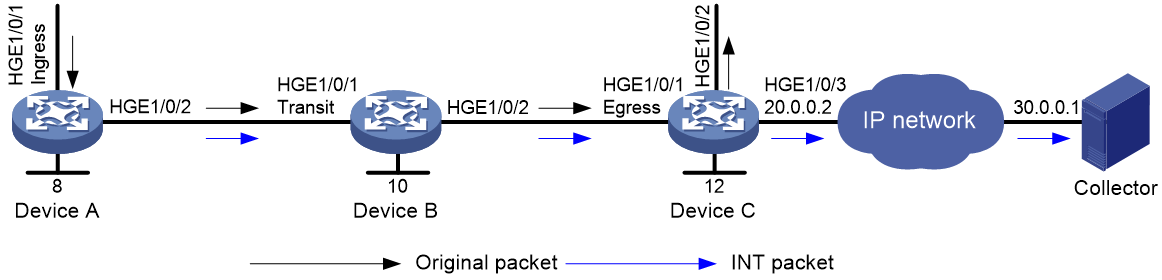
Example: Configuring common INT
Network configuration
As shown in Figure 4, configure common INT to send INT packets to the collector.
Procedure
1. Assign IP addresses to interfaces and configure routes. Make sure the network connections are available. (Details not shown.)
2. Configure Device C:
# Specify 11 as the device ID of the exit node.
<DeviceC> system-view
[DeviceC] telemetry ifa device-id 11
# Specify HundredGigE 1/0/1 as the egress interface.
[DeviceC] interface hundredgige 1/0/1
[DeviceC-HundredGigE1/0/1] telemetry ifa role egress
[DeviceC-HundredGigE1/0/1] quit
# Configure addressing parameters to encapsulate in INT packets sent to the collector.
[DeviceC] telemetry ifa collector source 20.0.0.2 destination 30.0.0.1 source-port 12 destination-port 14
# Enable INT globally.
[DeviceC] telemetry ifa global enable
3. Configure Device B:
# Specify 10 as the device ID of the transit node.
<DeviceB> system-view
[DeviceB] telemetry ifa device-id 10
# Specify HundredGigE 1/0/1 as the transit interface.
[DeviceB] interface hundredgige 1/0/1
[DeviceB-HundredGigE1/0/1] telemetry ifa role transit
[DeviceB-HundredGigE1/0/1] quit
# Enable INT globally.
[DeviceB] telemetry ifa global enable
4. Configure Device A:
# Specify 9 as the device ID of the entry node.
<DeviceA> system-view
[DeviceA] telemetry ifa device-id 9
# Specify HundredGigE 1/0/1 as the ingress interface.
[DeviceA] interface hundredgige 1/0/1
[DeviceA-HundredGigE1/0/1] telemetry ifa role ingress
[DeviceA-HundredGigE1/0/1] quit
# Create a sampler named samp in random sampling mode, and set the sampling rate to 8. One packet from 256 packets is selected.
[DeviceA] sampler samp mode random packet-interval n-power 8
# Create a traffic class named classifier1, and use destination MAC address a08c-fdd7-fd99 as the match criterion in the traffic class.
[DeviceA] traffic classifier classifier1
[DeviceA-classifier-classifier1] if-match destination-mac a08c-fdd7-fd99
[DeviceA-classifier-classifier1] quit
# Create a traffic behavior named behavior1, and configure the action of mirroring traffic to the INT processor.
[DeviceA] traffic behavior behavior1
[DeviceA-behavior-behavior1] mirror-to ifa-processor sampler samp
[DeviceA-behavior-behavior 1] quit
# Create a QoS policy named ifa1, and associate traffic class classifier1 with traffic behavior behavior1 in the QoS policy.
[DeviceA] qos policy ifa1
[DeviceA-qospolicy-ifa1] classifier classifier1 behavior behavior1
[DeviceA-qospolicy-ifa1] quit
# Apply QoS policy ifa1 to the incoming traffic of HundredGigE 1/0/1.
[DeviceA] interface hundredgige 1/0/1
[DeviceA-HundredGigE1/0/1] qos apply policy ifa1 inbound
[DeviceA-HundredGigE1/0/1] quit
# Enable INT globally.
[DeviceA] telemetry ifa global enable
Verify the configuration
# Verify the configuration on Device A.
[DeviceA] display qos policy interface hundredgige 1/0/1 inbound
Interface: HundredGigE1/0/1
Direction: Inbound
Policy: ifa1
Classifier: classifier1
Operator: AND
Rule(s) :
If-match destination-mac a08c-fdd7-fd99
Behavior: behavior1
Mirroring:
Mirror to the ifa-processor sampler samp
[DeviceA] display telemetry ifa
Telemetry ifa status : Enabled
Telemetry ifa packet-drop : Disabled
Telemetry ifa device-id: 9
Telemetry ifa role:
HundredGigE1/0/1: Ingress
# Verify the configuration on Device B.
[DeviceB] display telemetry ifa
Telemetry ifa status : Enabled
Telemetry ifa packet-drop : Disabled
Telemetry ifa device-id: 10
Telemetry ifa role:
HundredGigE1/0/1: Transit
# Verify the configuration on Device C.
[DeviceC] display telemetry ifa
Telemetry ifa status : Enabled
Telemetry ifa packet-drop : Disabled
Telemetry ifa device-id: 11
Telemetry ifa role:
HundredGigE1/0/1: Egress
Telemetry ifa collector:
Source IP: 20.0.0.2
Destination IP: 30.0.0.1
Source-port: 12
Destination-port: 14
Example: Configuring flexible INT
Network configuration
As shown in Figure 5, configure flexible INT to send INT packets to the collector.
Procedure
1. Assign IP addresses to interfaces and configure routes. Make sure the network connections are available. (Details not shown.)
2. Configure Device C:
# Specify 11 as the device ID of the exit node.
<DeviceC> system-view
[DeviceC] telemetry ifa device-id 11
# Create user-defined ACL 5000, and configure a rule to match INT packets with source IP address 192.168.1.2.
[DeviceC] acl user-defined 5000
[DeviceC-acl-user-5000] rule permit 253 source 192.168.1.2 0
[DeviceC-acl-user-5000] rule permit 253 source 192.168.1.2 0
[DeviceC-acl-user-5000] quit
# Configure the action of adding collected data to incoming INT packets and dropping the original INT packets on HundredGigE 1/0/1.
[DeviceC] interface hundredgige 1/0/1
[DeviceC-HundredGigE1/0/1] telemetry ifa 1 acl user-defined 5000 action add-metadata drop
[DeviceC-HundredGigE1/0/1] quit
# Configure addressing parameters to encapsulate in INT packets sent to the collector.
[DeviceC] telemetry ifa collector source 20.0.0.2 destination 30.0.0.1 source-port 12 destination-port 14
# Enable INT globally.
[DeviceC] telemetry ifa global enable
3. Configure Device B:
# Specify 10 as the device ID of the transit node.
<DeviceB> system-view
[DeviceB] telemetry ifa device-id 10
# Create user-defined ACL 5000, and configure a rule to match INT packets with source IP address 192.168.1.2.
[DeviceB] acl user-defined 5000
[DeviceB-acl-user-5000] rule permit 253 source 192.168.1.2 0
[DeviceB-acl-user-5000] rule permit 253 source 192.168.1.2 0
[DeviceB-acl-user-5000] quit
# Configure the action of mirroring INT packets on HundredGigE 1/0/1 to the INT processor.
[DeviceB] interface hundredgige 1/0/1
[DeviceB-HundredGigE1/0/1] telemetry ifa 1 acl user-defined 5000 action add-metadata
[DeviceB-HundredGigE1/0/1] quit
# Enable INT globally.
[DeviceB] telemetry ifa global enable
4. Configure Device A:
# Specify 9 as the device ID of the entry node.
<DeviceA> system-view
[DeviceA] telemetry ifa device-id 9
# Create a sampler named samp in random sampling mode, and set the sampling rate to 8. One packet from 256 packets is selected.
[DeviceA] sampler samp mode random packet-interval n-power 8
# Create IPv4 basic ACL 2000, and configure a rule to match packets with source IP address 192.168.1.2.
[DeviceA] acl basic 2000
[DeviceA-acl-ipv4-basic-2000] rule permit source 192.168.1.2 0
[DeviceA-acl-ipv4-basic-2000] quit
# Configure the action of mirroring original packets on HundredGigE 1/0/1 to the INT processor.
[DeviceA] interface hundredgige 1/0/1
[DeviceA-HundredGigE1/0/1] telemetry ifa 2 acl 2000 action mirror-to-processor sampler samp
[DeviceA-HundredGigE1/0/1] quit
# Enable INT globally.
[DeviceA] telemetry ifa global enable
Verify the configuration
# Verify the configuration on Device A.
[DeviceA] display telemetry ifa
Telemetry ifa status : Enabled
Telemetry ifa packet-drop : Disabled
Telemetry ifa device-id: 9
Telemetry ifa action:
HundredGigE1/0/1:
Telemetry ifa 1 acl 2000 action mirror-to-processor sampler samp
# Verify the configuration on Device B.
[DeviceB] display telemetry ifa
Telemetry ifa status : Enabled
Telemetry ifa packet-drop : Disabled
Telemetry ifa device-id: 10
Telemetry ifa action:
HundredGigE1/0/1:
Telemetry ifa 1 acl user-defined 5000 action add-metadata
# Verify the configuration on Device C.
[DeviceC] display telemetry ifa
Telemetry ifa status : Enabled
Telemetry ifa packet-drop : Disabled
Telemetry ifa device-id: 11
Telemetry ifa action:
HundredGigE1/0/1:
Telemetry ifa 1 acl user-defined 5000 action add-metadata drop
Telemetry ifa collector:
Source IP: 20.0.0.2
Destination IP: 30.0.0.1
Source-port: 12
Destination-port: 14