- Table of Contents
- Related Documents
-
| Title | Size | Download |
|---|---|---|
| 01-Hardware Information and Specifications | 2.97 MB |
1 Product models and technical specifications
1600W AC power supply (PSR1600B-12A-B)
2000W DC power supply (PSR2000-12D-B)
7 Cable routing recommendations
1 Product models and technical specifications
Product models
H3C S9820-8C and S9820-8C-SAN switches are high-density intelligent 100G/400G switches developed for data centers, providing powerful hardware forwarding capacity and abundant data center features.
This document is applicable to the following switch models:
|
Product model |
Product code |
|
S9820-8C |
LS-9820-8C |
|
S9820-8C-SAN |
LS-9820-8C-SAN |
|
|
NOTE: · To obtain the purchase information, see the product data sheet at https://www.h3c.com/en/Products_and_Solutions/InterConnect/Switches/ and pay attention to the switch product lifecycle management announcement at https://www.h3c.com/en/Support/Policy_Dynamics/Management_Strategy/Products_End_of_Life_Announcement/Switches/. · For information about product and software compatibility, see the release notes. |
Technical specifications
Table1-1 Technical specifications
|
Item |
S9820-8C/S9820-8C-SAN |
|
Physical specifications |
|
|
Dimensions (H × W × D) |
130.5 × 440 × 760 mm (5.14 × 17.32 × 29.92 in) |
|
Dimensions (H × W × D, with package materials) |
310 × 575 × 975 mm (12.20 × 22.64 × 38.39 in) |
|
Weight (fully configured with fan modules, power supplies, and interface modules, excluding transceiver modules and cables) |
≤ 45 kg (99.21 lb) |
|
Technical specifications |
|
|
Processor |
· S9820-8C: 4 cores, 2.2 GHz · S9820-8C-SAN: 8 cores, 2.2 GHz |
|
DRAM memory |
8 GB |
|
NOR flash |
32 MB *2 (primary and backup) |
|
NAND flash |
8GB eMMC |
|
Interface types and quantity |
|
|
Console port |
· 1 × mini USB console port · 1 × serial console port |
|
Management Ethernet port |
· 1 × 10/100/1000BASE-T copper port · 1 × SFP port |
|
USB port |
1 |
|
IRF physical ports |
Not supported |
|
Fan modules, power supplies, and interface modules |
|
|
Power supply slot |
4 |
|
Interface module slot |
8 |
|
Fan module slot |
5 |
|
Power supply specifications |
|
|
Power input |
AC input and HVDC input |
|
Power specifications |
See "Power supplies" |
|
Power consumption |
|
|
Typical power consumption (Fully configured with copper cables, at 50% load) |
· Configured with LSWM116H interface modules: 921 W · Configured with LSWM116HC interface modules: 1132 W · Configured with LSWM1M4CD interface modules: 820 W |
|
Maximum power consumption (Fully configured with transceiver modules, at 100% load) |
· Configured with LSWM116H interface modules: 1818 W · Configured with LSWM116HC interface modules: 2030 W · Configured with LSWM1M4CD interface modules: 1655 W |
|
Thermal consumption |
|
|
Typical thermal consumption |
· Configured with LSWM116H interface modules: 3143 BTU/hr · Configured with LSWM116HC interface modules: 3862 BTU/hr · Configured with LSWM1M4CD interface modules: 2798 BTU/hr |
|
Maximum thermal consumption |
· Configured with LSWM116H interface modules: 6203 BTU/hr · Configured with LSWM116HC interface modules: 6927 BTU/hr · Configured with LSWM1M4CD interface modules: 5647 BTU/hr |
|
Heat dissipation |
|
|
Heat dissipation method |
Air cooling |
|
Ventilation aisles |
Front-to-rear (from the port side to the power supply side) |
|
Reliability and availability |
|
|
Power supply redundancy |
2+1 or 2+2 redundancy |
|
Fan module redundancy |
4+1 redundancy |
|
Hot swapping |
Power supplies and fan modules support hot swapping Interface modules support hot swapping, but do not hot swap an interface module when the switch is starting up |
|
Mean time between failure (MTBF) (year) |
· S9820-8C: 38.8 · S9820-8C-SAN: 40.3 |
|
Mean time to repair (MTTR) (hour) |
· S9820-8C: 1 · S9820-8C-SAN: 0.5 |
|
Availability |
· S9820-8C: 99.999709% · S9820-8C-SAN: 99.999858% |
|
Environment specifications |
|
|
Sound pressure level at 27°C (80.6°F) |
65.6 dB(A) |
|
Altitude |
–60 m to +5000 m (–196.85 ft to +16404.20 ft) |
|
Operating temperature |
0°C to 45°C (32°F to 113°F) Note: The allowed maximum temperature decreases by 0.33 °C (32.59°F) as the altitude increases by 100 m (328.08 ft) from 0 m (0 ft). If you use a QSFP-100G-ZR4-WDM1300 transceiver module, the operating temperature must be in the range of 0°C to 40°C (32°F to 104°F). |
|
Storage temperature |
–40°C to +70°C (–40°F to +158°F) |
|
Humidity |
5% RH to 95% RH, noncondensing |
|
Compliance |
|
|
Product compliance |
· Safety standards · EMC standards · Environmental and eco-friendly standards |
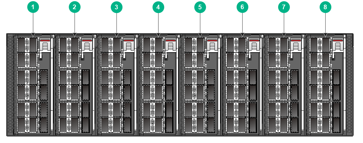
2 Chassis views
|
(1) Interface module 1 |
(2) Interface module 2 |
|
(3) Interface module 3 |
(4) Interface module 4 |
|
(5) Interface module 5 |
(6) Interface module 6 |
|
(7) Interface module 7 |
(8) Interface module 8 |
|
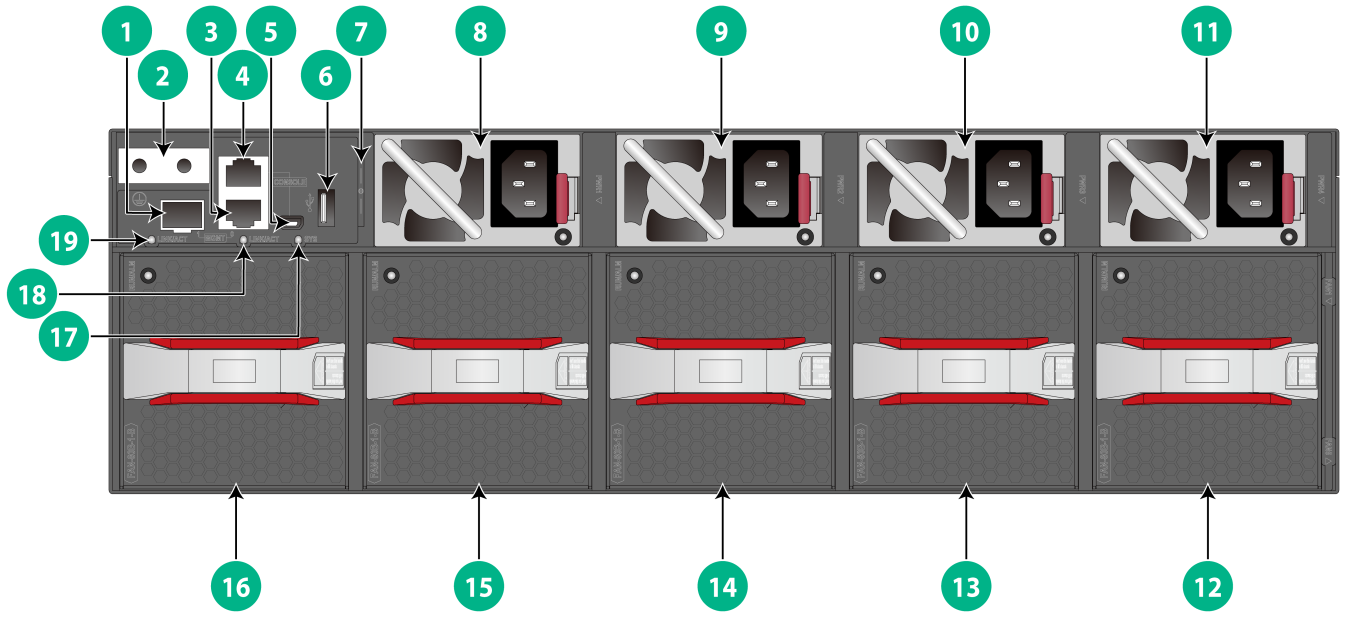
(1) Fiber management Ethernet port (numbered 1) |
(2) Grounding point |
|
(3) Copper management Ethernet port (numbered 0) |
(4) Serial console port |
|
(5) Mini USB console port |
(6) USB port |
|
(7) Serial label pull tab |
(8) Power supply 1 |
|
(9) Power supply 2 |
(10) Power supply 3 |
|
(11) Power supply 4 |
(12) Fan module 5 |
|
(13) Fan module 4 |
(14) Fan module 3 |
|
(15) Fan module 2 |
(16) Fan module 1 |
|
(17) System status LED (SYS) |
(18) Copper management Ethernet port LED (LINK/ACT) |
|
(19) Fiber management Ethernet port LED (LINK/ACT) |
|
The ESN serial number and MAC address of the switch can be found on the serial label pull tab.
The switch came with power supply slots PWR1 and PWR2 empty and power supply slots PWR3 and PWR4 each installed with a filler panel. You can install two to four power supplies for the switch as needed. In Figure2-2, PSR1600B-12A-B power supplies are installed in the four power supply slots.
The switch came with the five fan module slots empty. You must install five fan modules of the same model for the switch. In Figure2-2, FAN-80B-1-B fan modules are installed in the five fan module slots.
The switch came with the eight interface module slots each installed with a filler panel. You can install one to eight interface modules for the switch as needed. In Figure2-1, LSWM116H interface modules are installed in the eight interface module slots.
The switch supports shipping with fan modules and power supplies installed. To purchase a switch preinstalled with fans modules and power supplies, contact marketing staff.
3 FRUs
The switch uses modular design. Table3-1 describes the FRUs available for the switch.
Table3-1 FRUs available for the switch
|
FRUs |
S9820-8C/S9820-8C-SAN |
|
Power supplies |
|
|
PSR1600B-12A-B |
Yes |
|
PSR2000B-12D-B |
Yes, in R6715P01 and later versions |
|
Fan modules |
|
|
FAN-80B-1-B |
Yes |
|
Interface modules |
|
|
LSWM116H |
Yes |
|
LSWM116HC |
Yes, in Release 6635 and later versions |
|
LSWM1M4CD |
Yes, in Release 6635 and later versions |
The switch can operate correctly with two power supplies. You can install three power supplies for 2+1 redundancy or four power supplies for 2+2 redundancy.
To ensure heat dissipation, make sure all fan module slots are installed with fan modules and install fan modules of the same model on the switch as a best practice.
Power supplies
|
|
WARNING! When the switch has power supplies in redundancy, you can replace a power supply without powering off the switch. To avoid device damage and personal injury, make sure the power supply is powered off before you replace it. |
The switch uses removable power supplies.
1600W AC power supply (PSR1600B-12A-B)
View
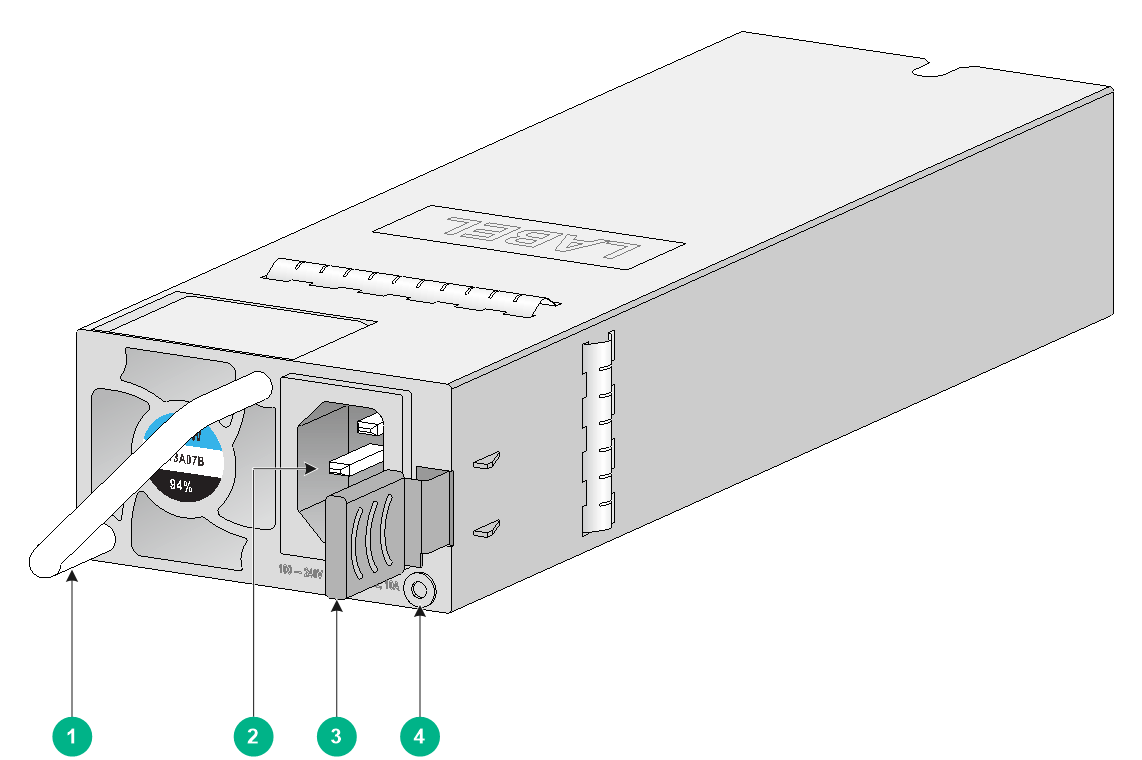
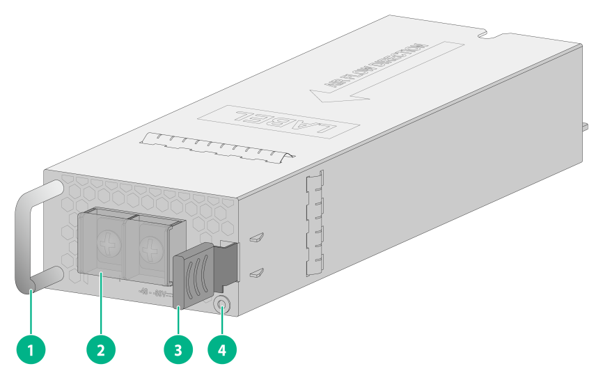
Figure3-1 PSR1600B-12A-B power supply
|
(1) Handle |
(2) AC power receptacle |
|
(3) Latch |
(4) Power supply alarm LED |
For information about the power supply alarm LED, see "Power supply alarm LED."
Features
PSR1600B-12A-B is a power supply with AC input and DC output. It can provide up to 1600 W of output. Table3-2 describes the features provided by the PSR1600B-12A-B power supply.
Table3-2 Features provided by the PSR1600B-12A-B power supply
|
Feature |
Description |
|
Protection function |
Protection for input overcurrent, input undervoltage, output overcurrent, output overvoltage, output shortcircuit, and overtemperature. |
|
Support for redundancy |
The power supplies can be connected in parallel to achieve N+1 or N+N redundancy and load balancing. |
|
Support for hot swapping |
You can install or remove a power supply when the switch is operating correctly. |
Technical specifications
Table3-3 Technical specifications
|
Item |
Specification |
|
Dimensions (H × W × D) |
40.2 × 73.5 × 253.8 mm (1.58 × 2.89 × 9.99 in), including the handle |
|
Weight |
1.09 kg (2.40 lb) |
|
Rated AC input voltage range |
100 VAC to 240 VAC @ 50 or 60 Hz |
|
Max AC input voltage range |
90 VAC to 290 VAC @ 47 to 63 Hz |
|
Rated HVDC input voltage |
240 VDC |
|
Max HVDC input voltage range |
180 VDC to 320 VDC |
|
Rated input current |
10.5 A |
|
Rated output current |
131 A |
|
Rated output voltage |
12 V |
|
Rated output power |
1600 W |
|
Melting current of power supply fuse |
10 A/ 250 V |
2000W DC power supply (PSR2000-12D-B)
View
Figure3-2 PSR2000-12D-B power supply
|
(1) Handle |
(2) Protection cover |
|
(3) Latch |
(4) Power supply alarm LED |
For information about the power supply alarm LED, see "Power supply alarm LED."
Features
PSR2000-12D-B is a power supply with DC input and DC output. It can provide up to 2000 W of output. Table3-4 describes the features provided by the PSR2000-12D-B power supply.
Table3-4 Features provided by the PSR2000-12D-B power supply
|
Feature |
Description |
|
Protection function |
Protection for input undervoltage, output undervoltage, output overvoltage, shortcircuit, output overcurrent, and overtemperature. |
|
Support for redundancy |
The power supplies can be connected in parallel to achieve M+N redundancy and load balancing. |
|
Support for hot swapping |
You can install or remove a power supply when the switch is operating correctly. |
Technical specifications
Table3-5 Technical specifications
|
Item |
Specification |
|
Dimensions (H × W × D) |
40.2 × 73.5 × 225 mm (1.58 × 2.89 × 8.86 in), including the handle |
|
Weight |
1.07 kg (2.36 lb) |
|
Rated input voltage range |
–48 VDC to –60 VDC |
|
Max input voltage range |
–40 VDC to –72 VDC |
|
Rated input current |
60 A |
|
Rated output current |
12 V/167 A, 12 VSB/2 A |
|
Rated output voltage |
12 V |
|
Rated output power |
2000 W |
|
Melting current of power supply fuse |
80 A |
Fan modules
|
|
CAUTION: The switch has five fan module slots. To ensure good ventilation of the switch, follow these guidelines to install and remove fan modules: · The switch comes with the fan module slots empty. As a best practice to ensure adequate heat dissipation, install fan modules of the same model on the switch. Before powering on the switch, make sure the number of installed fan modules meets the minimum requirement. · Make sure all slots have a module or filler panel installed when the switch is operating. · If multiple fan modules fail on an operating switch, do not remove the fan modules at the same time. Replace the fan modules one after another and finish replacing each fan module within 3 minutes. |
FAN-80B-1-B
View
Figure3-3 FAN-80B-1-B fan module
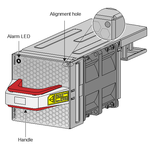
For information about the alarm LED, see "Fan module alarm LED."
Features
The FAN-80B-1-B fan module draws air from the port side to the power supply side. The fan module is small, hot swappable, and can automatically adjust the fan speed according to the device temperature.
Technical specifications
Table3-6 Technical specifications
|
Item |
Specification |
|
Dimensions (H × W × D) |
84 × 81 × 240 mm (3.31 × 3.19 × 9.45 in), including the handle |
|
Fans |
1 |
|
Weight |
0.9 kg (1.98 lb) |
|
Airflow direction |
Air exhausted from the fan module faceplate |
|
Max fan speed |
12800 R.P.M |
|
Max airflow |
130 CFM (3.68 m3/min) |
|
Operating voltage |
12 V |
|
Max power consumption |
102 W |
Interface modules
The switch provides eight interface module slots. Table3-7 describes the interface modules available for the switch.
You can install an interface module in any interface module slot on the switch.
You can install or remove an interface module when the switch is operating correctly. Do not install or remove an interface module on a starting switch.
Table3-7 Available interface modules
|
Model |
Description |
Port type and number |
|
LSWM116H |
16-port QSFP28 Ethernet optical interface module |
16 × QSFP28 ports |
|
LSWM116HC |
16-port QSFP28 Ethernet optical interface module |
16 × QSFP28 ports |
|
LSWM1M4CD |
4-port 400GBASE Ethernet optical interface module(QSFP-DD) |
4 × QSFP-DD ports |
LSWM116H
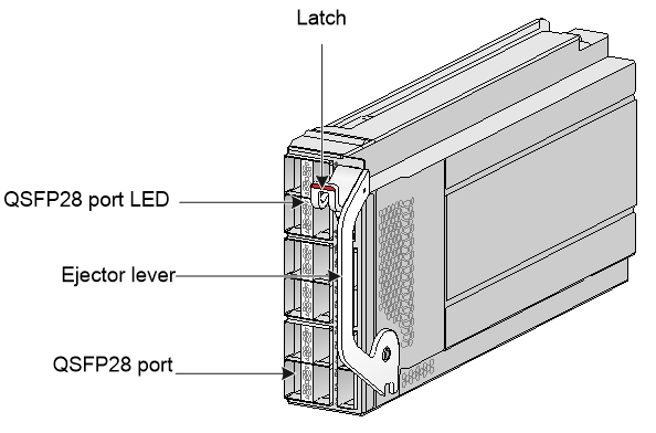
The LSWM116H interface module provides 16 QSFP28 ports.
Figure3-4 LSWM116H front panel

Ports and LEDs
For information about the QSFP28 port and modules and cables available for the port, see "QSFP28 port."
For information about the QSFP28 port LED, see "QSFP28 port LED."
Technical specifications
Table3-8 Technical specifications
|
Item |
Specifications |
|
Dimensions (H × W × D) |
50 × 127.3 × 262.2 mm (1.97 × 5.01 × 10.32 in), including the connector but excluding the ejector lever |
|
Weight |
1.4 kg (3.09 lb) |
|
Power consumption (typical) |
52 W |
|
Power consumption (fully loaded) |
87 W |
LSWM116HC
The LSWM116HC interface module provides 16 QSFP28 ports.
Figure3-5 LSWM116HC front panel
Ports and LEDs
For information about the QSFP28 port and modules and cables available for the port, see "QSFP28 port."
For information about the QSFP28 port LED, see "QSFP28 port LED."
Technical specifications
Table3-9 Technical specifications
|
Item |
Specifications |
|
Dimensions (H × W × D) |
50 × 127.3 × 262.2 mm (1.97 × 5.01 × 10.32 in), including the connector but excluding the ejector lever |
|
Weight |
1.5 kg (3.31 lb) |
|
Power consumption (typical) |
78 W |
|
Power consumption (fully loaded) |
113 W |
LSWM1M4CD
The LSWM1M4CD interface module provides 4 QSFP-DD ports.
Figure3-6 LSWM1M4CD front panel
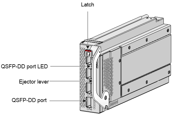
Ports and LEDs
For information about the QSFP-DD port and modules and cables available for the port, see "QSFP-DD port."
For information about the QSFP-DD port LED, see "QSFP-DD port LED."
Technical specifications
Table3-10 Technical specifications
|
Item |
Specifications |
|
Dimensions (H × W × D) |
50 × 127.3 × 262.2 mm (1.97 × 5.01 × 10.32 in), including the connector but excluding the ejector lever |
|
Weight |
1.3 kg (2.87 lb) |
|
Power consumption (typical) |
39 W |
|
Power consumption (fully loaded) |
87 W |
4 Ports
As a best practice, use H3C transceiver modules and cables for the switch. H3C transceiver modules and cables are subject to change over time. For the most up-to-date list of H3C transceiver modules and cables, contact H3C Support or marketing staff.
For information about the specifications of H3C transceiver modules and cables, see H3C Transceiver Modules User Guide.
The switch uses high-power ports in high density. Bringing up the ports simultaneously takes a comparatively long time. To reduce the time to bring up a port, the system does not turn off the laser transmitter on the transceiver module when shutting down the port.
Console port
The switch has a serial console port and a mini USB console port.
Table4-1 Console port specifications
|
Item |
Serial console port |
Mini USB console port |
|
Connector type |
RJ-45 |
USB mini-Type B |
|
Compliant standard |
EIA/TIA-232 |
USB 2.0 |
|
Operating mode |
Duplex Universal Asynchronous Receiver/Transmitter (duplex UART) |
Mini USB interface Universal Asynchronous Receiver/Transmitter (UART) |
|
Transmission baud rate |
9600 bps (default) to 115200 bps |
|
|
Services |
· Provides connection to an ASCII terminal. · Provides connection to the serial port of a local terminal (a PC for example) or remote terminal (through a pair of modems) running a terminal emulation program. |
· Provides connection to an ASCII terminal. · Provides connection to the USB port of a local terminal (a PC for example) running a terminal emulation program. |
A console port and a mini USB console port cannot be connected simultaneously. If both ports are connected, only the mini USB console port takes effect.
Management Ethernet port
The switch has two management Ethernet ports: a copper management port and an SFP management port. You can connect the ports to a local PC for software loading and debugging or to a remote management station for remote management.
Table4-2 Management Ethernet port specifications
|
Item |
Specification |
|
Connector type |
· 10/100/1000BASE-T management port: RJ-45. · SFP management port: LC. |
|
Compliant standard |
· 10/100/1000BASE-T management port: IEEE802.3ab. · SFP management port: IEEE802.3z. |
|
Port transmission rate, duplex mode, and auto MDI/MDI-X |
· 10/100/1000BASE-T management port: ¡ 10/100 Mbps, half/full duplex, auto MDI/MDI-X. ¡ 1000 Mbps, full duplex, auto MDI/MDI-X. · SFP management port: 1000/100 Mbps, full duplex. |
|
Transmission medium and max transmission distance |
· 10/100/1000BASE-T management port: 100 m (328.08 ft) over category-5 UTP cable. · SFP management port: See FE SFP transceiver modules in Table4-3 and GE SFP transceiver modules in Table4-4. |
|
Functions and services |
Software upgrade and network management. |
Table4-3 FE SFP transceiver modules available for the SFP management port
|
FE SFP transceiver module |
Central wavelength (nm) |
Connector |
Fiber type and diameter (µm) |
Max transmission distance |
|
SFP-FE-SX-MM1310-A |
1310 |
LC |
Multi-mode, 50/125 |
2 km (1.24 miles) |
|
Multi-mode, 62.5/125 |
||||
|
SFP-FE-LX-SM1310-A |
1310 |
LC |
Single-mode, 9/125 |
15 km (9.32 miles) |
Table4-4 GE SFP transceiver modules available for the SFP management port
|
GE SFP transceiver module |
Central wavelength (nm) |
Connector |
Cable/Fiber type and diameter (µm) |
Modal bandwidth (MHz × km) |
Max transmission distance |
|
SFP-GE-T SFP-GE-T-D |
N/A |
RJ-45 |
Twisted pair cable |
N/A |
100 m (328.08 ft) |
|
SFP-GE-SX-MM850-A SFP-GE-SX-MM850-D |
850 |
LC |
Multi-mode, 50/125 |
500 |
550 m (1804.46 ft) |
|
400 |
500 m (1640.42 ft) |
||||
|
Multi-mode, 62.5/125 |
200 |
275 m (902.23 ft) |
|||
|
160 |
200 m (656.17 ft) |
||||
|
SFP-GE-LX-SM1310-A |
1310 |
LC |
Single-mode, 9/125 |
N/A |
10 km (6.21 miles) |
|
Multi-mode, 50/125 |
500 or 400 |
550 m (1804.46 ft) |
|||
|
Multi-mode, 62.5/125 |
500 |
550 m (1804.46 ft) |
|||
|
SFP-GE-LX-SM1310-D |
1310 |
LC |
Single-mode, 9/125 |
N/A |
10 km (6.21 miles) |
USB port
The switch has one OHCI-compliant USB 2.0 port that can upload and download data at a rate up to 480 Mbps. You can use this USB port to access the file system on the flash of the switch, for example, to upload or download application and configuration files.
The USB port supplies power as per USB 2.0 specifications. Use only USB 2.0-compliant USB devices for the USB port. The port might not identify USB devices that are not compliant with USB 2.0.
|
|
NOTE: USB devices from different vendors vary in compatibilities and drivers. H3C does not guarantee correct operation of USB devices of all vendors on the switch. If a USB device fails to operate on the switch, replace it with one from another vendor. |
QSFP28 port
Table4-5 QSFP28 port specifications
|
Item |
Specification |
|
Interface name |
40 GE/100 GE QSFP28 Ethernet optical interface |
|
Product compatibility |
· LSWM116H interface module: 16 QSFP28 ports · LSWM116HC interface module: 16 QSFP28 ports |
|
Connector |
LC/MPO |
|
Description |
The 40 GE/100 GE QSFP28 Ethernet optical interfaces are mainly used for transmitting and receiving 40 GE/100 GE Ethernet optical interface services |
|
Compliant standard |
IEEE802.3ba |
|
Optical interface attribute |
Depends on transceiver modules and cables |
|
Operating mode |
Full duplex |
|
Transceiver modules and cables |
· 100G QSFP28 modules · 100G QSFP28 copper cables · 100G QSFP28 fiber cables (AOC) · 100G QSFP28 to 4*25G SFP28 copper cables · 40G QSFP+ modules · 40G QSFP+ copper cables · 40G QSFP+ fiber cables (AOC) · 40G QSFP+ to 4*10G SFP+ copper cables NOTE: For information about support for transceiver modules and cables of a QSFP28 port, see H3C S9820-64H & S9820-8C & S9820-8C-SAN Switches Transceiver Module Compatibility Matrix. |
|
Support for interface splitting |
· LSWM116H: Interface splitting is not supported in the current software version. For the most recent support information, see the most up-to-date release notes (software feature changes). For more information, contact H3C Support or marketing staff. · LSWM116HC: Interface splitting is not supported. |
|
Other restrictions |
A 100G port on the device might fail to come up when a 100G DAC cable is used to connect the port to an Intel network card, for example, Intel (rainbow) Eth E810-CQDA2. As a best practice, use an AOC cable or transceiver module for connection to the Intel network card. |
QSFP-DD port
Table4-6 QSFP-DD port specifications
|
Item |
Specification |
|
Interface name |
400 GE QSFP-DD Ethernet optical interface |
|
Product compatibility |
LSWM1M4CD interface module: 4 QSFP-DD ports |
|
Connector |
LC/MPO |
|
Description |
The 400 GE QSFP-DD Ethernet optical interfaces are mainly used for transmitting and receiving 400 GE Ethernet optical interface services |
|
Compliant standard |
IEEE 802.3bs |
|
Optical interface attribute |
Depends on transceiver modules and cables |
|
Operating mode |
Full duplex |
|
Transceiver modules and cables |
· 400G QSFP-DD modules · 400G QSFP-DD copper cables · 400G 1-to-2 cables (being developed) NOTE: For information about support for transceiver modules and cables of a QSFP-DD port, see H3C S9820-64H & S9820-8C & S9820-8C-SAN Switches Transceiver Module Compatibility Matrix. |
|
Support for splitting |
A 400G QSFP-DD port can be split into two 200G ports. |
5 LEDs
System status LED
The system status LED shows the operating status of the switch.
Table5-1 System status LED description
|
LED mark |
Status |
Description |
|
SYS |
Steady green |
The switch is operating correctly. |
|
Flashing green |
The switch is performing power-on self-test (POST). |
|
|
Steady red |
The system has failed to pass POST or a fault has occurred. |
|
|
Flashing blue (3 Hz) |
Helps identifying the switch. To identify the switch location, execute the locator blink blink-time command. This LED will flash blue at 3 Hz. |
|
|
Off |
The switch is powered off or has failed to start up. |
QSFP28 port LED
Table5-2 QSFP28 port LED description
|
LED status |
Description |
|
Steady green |
A transceiver module or cable has been correctly installed in the port. The port has a link and is operating at 100 Gbps. |
|
Flashing green |
The port is sending or receiving data at 100 Gbps. |
|
Steady yellow |
A transceiver module or cable has been correctly installed in the port. The port has a link and is operating at 40 Gbps. |
|
Flashing yellow (3 Hz) |
The port is sending or receiving data at 40 Gbps. |
|
Off |
No transceiver module or cable has been installed in the port, or no link is present on the port. |
QSFP-DD port LED
Table5-3 QSFP-DD port LED description
|
LED status |
Description |
|
Steady green |
A transceiver module is installed in the port. The port is operating at its maximum speed of 400 Gbps, and a link is present on the port. |
|
Flashing green |
The port is sending or receiving data at its maximum speed of 400 Gbps. |
|
Steady yellow |
A transceiver module is installed in the port. The port is operating at a speed lower than the maximum speed. |
|
Flashing yellow (3 Hz) |
The port is sending or receiving data at a speed lower than the maximum speed. |
|
Off |
No transceiver module is installed in the port, or no link is present on the port. |
Management Ethernet port LEDs
The switch provides a LINK/ACT LED for each management Ethernet port to indicate their operating status.
Table5-4 Management Ethernet port LED description
|
LED mark |
Status |
Description |
|
LINK/ACT |
Off |
No link is present on the port. |
|
Steady green |
The port is operating at 1000 Mbps. |
|
|
Flashing green |
The port is receiving or sending data at 1000 Mbps. |
|
|
Steady yellow |
The port is operating at 100 Mbps. |
|
|
Flashing yellow |
The port is receiving or sending data at 100 Mbps. |
Power supply alarm LED
Table5-5 Description for the alarm LED on a PSR1600B-12A-B power supply
|
Status |
Description |
|
Steady green |
The power supply is operating correctly and in active state. |
|
Flashing green at 1 Hz |
The power supply is operating correctly and in standby state. |
|
Flashing green at 2 Hz |
The power supply software is being upgraded. |
|
Steady amber |
The power supply is faulty or has entered self-protection mode. |
|
Flashing amber at 1 Hz |
An alarm has occurred on the power supply when one of the following conditions exists on the power supply but the power supply does not enter protection state: · Output overvoltage. · Output undervoltage. · Output overcurrent. · Output power overload. · Overtemperature. |
|
Flashing amber at 2 Hz |
The power supply does not have input power but the power supplies working in parallel with it have input power. |
|
Off |
Neither this power supply nor power supplies working in parallel with it have input power. |
Table5-6 Description for the alarm LED on a PSR2000-12D-B power supply
|
Status |
Description |
|
Steady green |
The power supply is operating correctly. |
|
Flashing green (once per second) |
The power supply is updating software. |
|
Flashing green (once every two seconds) |
The power supply has correct power input and is in standby state with 12 V standby output and without 12 V main output. |
|
Steady yellow |
The power supply is faulty. |
|
Flashing yellow (once per second) |
The power supply does not have power input, but other power supplies have correct power input. |
|
Flashing yellow (once every two seconds) |
The power supply is operating correctly, but an alarm has occurred (such as input undervoltage, output overcurrent, and overtemperature). |
|
Off |
No power input. |
Fan module alarm LED
A FAN-80B-1-B fan module provides an alarm LED.
Table5-7 Description for the alarm LED on a FAN-80B-1-B fan module
|
Status |
Description |
|
Steady green |
The fan module is operating correctly. |
|
Steady red |
The fan module is faulty. |
|
Off |
The fan module is not installed securely or no power is present. |
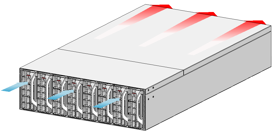
6 Cooling system
|
|
CAUTION: The chassis and power supplies use separate air aisles. Make sure the two aisles are not blocked when the switch is operating. |
The switch uses a highly efficient front-rear air aisle cooling system to ensure adequate heat dissipation and improve system reliability. Consider the ventilation design at the installation site when you plan the installation location for the switch.
Table6-1 Fan module options for the switch
|
Available fan module |
Airflow direction of the chassis |
|
FAN-80B-1-B |
From the port side to the power supply side |
Figure6-1 Airflow from the port side to the power supply side (with FAN-80B-1-B fan modules)
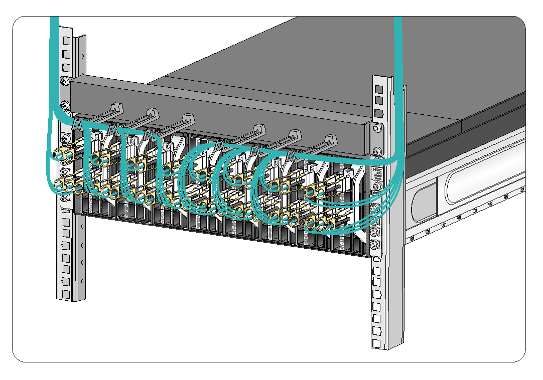
7 Cable routing recommendations
You can purchase one cable management frame for the switch and install it on the rack posts immediately above or below the switch as required. For more organized cabling, you can purchase two cable management frames so that the switch has a cable management frame installed both above and below it.
Route the signal cables along the left or right side of the cable management frame as required. Cable routing in Figure7-1 is for your reference.