- Table of Contents
- Related Documents
-
| Title | Size | Download |
|---|---|---|
| 01-Text | 13.60 MB |
Preventing electrostatic discharge
Grounding methods to prevent electrostatic discharge
Server models and chassis view
Front 8SFF SAS/SATA drive backplane
Front 8SFF UniBay drive backplane
Front 8LFF SAS/SATA drive backplane
Front 12LFF SAS/SATA drive backplane
Front 8SAS/SATA+4UniBay drive backplane
Front 4SAS/SATA+8UniBay drive backplane
Front 12LFF UniBay drive backplane
Front 17SAS/SATA+8UniBay drive backplane
Rear 2LFF SAS/SATA drive backplane
Rear 4LFF SAS/SATA drive backplane
Rear 2SFF SAS/SATA drive backplane
Rear 2SFF UniBay drive backplane
Rear 4SFF SAS/SATA drive backplane
Rear 4SFF UniBay drive backplane
Riser 4 assembly module (accommodating two FHFL PCIe modules)
Riser 3 assembly module (accommodating two HHHL PCIe modules)
Component installation guidelines
Storage controllers and power fail safeguard modules
Installing or removing the server
Airflow direction of the server
Temperature and humidity requirements
Equipment room height requirements
Corrosive gas concentration requirements
Installing cable management brackets
Connecting a mouse, keyboard, and monitor
Removing the server from a rack
Powering on and powering off the server
Configuring basic BIOS settings
Installing the operating system and hardware drivers
Installing the operating system
Replacing the server management module
Replacing riser cards and PCIe modules
Installing PCIe modules and a riser card on PCIe riser bay 3
Installing PCIe modules and a riser card on PCIe riser bay 4
Replacing a storage controller and a power fail safeguard module
Replacing a standard PCIe network adapter
Replacing an OCP network adapter
Replacing a SATA M.2 SSD and the front M.2 SSD expander module
Replacing a serial & DSD module
Replacing a chassis air baffle
Adding an LCD smart management module
Replacing an LCD smart management module
Installing and setting up a TCM or TPM
Installation and setup flowchart
Enabling the TCM or TPM in the BIOS
Configuring encryption in the operating system
Removing and installing a blank
12LFF (8 SAS/SATA + 4 UniBay) drives at the front
12LFF drives at the front + 2SFF UniBay drives at the rear
12LFF (4 SAS/SATA + 8 UniBay, LSI Expander) drives at the front
8SFF UniBay+8SFF UniBay+8SFF UniBay drives at the front
25SFF (17 SAS/SATA + 8 UniBay) drives at the front
Connecting the LCD smart management module cable
Connecting cables for the front M.2 SSD expander module
Connecting cables for OCP 3.0 network adapter 1
Connecting cables for riser cards
Connecting the supercapacitor cable
Monitoring the temperature and humidity in the equipment room
Updating firmware for the server
Security
Safety information
To avoid bodily injury or damage to the server, read the following information carefully before you operate the server.
General operating safety
To avoid bodily injury or damage to the server, follow these guidelines when you operate the server:
· Only H3C authorized or professional server engineers are allowed to install, service, repair, operate, or upgrade the server.
· Place the server on a clean, stable table or floor for servicing.
· Make sure all cables are correctly connected before you power on the server.
· To ensure good ventilation and proper airflow, follow these guidelines:
¡ Do not block the ventilation openings in the server chassis.
¡ Install blanks if the following module slots are empty:
- Drive bays.
- Fan bays.
- PCIe slots.
- Power supply slots.
¡ Do not operate the server in any of the following conditions:
- Access panel open or uninstalled.
- Air baffles uninstalled.
- PCIe slots, drive bays, fan bays, or power supply slots empty without blanks.
¡ Minimize the period for removing the access panel when operating hot-swappable components.
· To avoid being burnt, allow the server and its internal modules to cool before touching them.
· To avoid server damage caused by improper cooling, do not block the ventilation openings in the server chassis. When stacking the server with other devices in the cabinet, you must reserve a vertical gap of at least 2 mm (0.08 in) between the devices.
Electrical safety
|
|
WARNING! If you put the server in standby mode (system power LED in amber) with the power on/standby button on the front panel, the power supplies continue to supply power to some circuits in the server. To remove all power for servicing safety, you must first press the button, wait for the system to enter standby mode, and then remove the power cords from the server. |
To avoid bodily injury or damage to the server, follow these guidelines:
· Always use the power cords that came with the server.
· Do not use the power cords that came with the server for any other devices.
· Power off the server when installing or removing any components that are not hot swappable.
Battery safety
The server's system board contains a system battery, which is designed with a lifespan of 3 to 5 years.
If the server no longer automatically displays the correct date and time, you might need to replace the battery. When you replace the battery, follow these safety guidelines:
· Do not attempt to recharge the battery.
· Do not expose the battery to a temperature higher than 60°C (140°F).
· Do not disassemble, crush, puncture, short external contacts, or dispose of the battery in fire or water.
· Dispose of the battery at a designated facility. Do not throw the battery away together with other wastes.
Safety precautions
|
|
NOTE: Power instability or outage might cause data loss, service disruption, or damage to the server in the worst case. To protect the server from unstable power or power outage, use uninterrupted power supplies (UPSs) to provide power for the server. |
To avoid bodily injury or damage to the equipment, follow these guidelines when you rack mount a server:
· Mount the server in a standard 19-inch rack.
· Make sure the leveling jacks are extended to the floor and the full weight of the rack rests on the leveling jacks.
· Couple the racks together in multi-rack installations.
· Load the rack from the bottom to the top, with the heaviest hardware unit at the bottom of the rack.
· Get help to lift and stabilize the server during installation or removal, especially when the server is not fastened to the rails. As a best practice, a minimum of two people are required to safely load or unload a rack. A third person might be required to help align the server if the server is installed higher than check level.
· For rack stability, make sure only one unit is extended at a time. A rack might get unstable if more than one server unit is extended.
· Make sure the rack is stable when you operate a server in the rack.
· To maintain correct airflow and avoid thermal damage to the server, use blank panels to fill empty rack units.
ESD prevention
Preventing electrostatic discharge
Electrostatic charges that build up on people and tools might damage or shorten the lifespan of the system board and electrostatic-sensitive components.
To prevent electrostatic damage, follow these guidelines:
· Transport or store the server with the components in antistatic bags.
· Keep the electrostatic-sensitive components in separate antistatic bags until they arrive at an ESD-protected area.
· Place the components on a grounded surface before removing them from their antistatic bags.
· Avoid touching pins, leads, or circuitry.
Grounding methods to prevent electrostatic discharge
The following are grounding methods that you can use to prevent electrostatic discharge:
· Wear an ESD wrist strap and make sure it makes good skin contact and is reliably grounded.
· Take adequate personal grounding measures, including wearing antistatic clothing and static dissipative shoes.
· Use conductive field service tools.
· Use a portable field service kit with a folding static-dissipating work mat.
Safety sign conventions
To avoid bodily injury or damage to the server or its components, make sure you are familiar with the safety signs on the server chassis or its components.
|
Sign |
Description |
|
Circuit or electricity hazards are present. Only H3C authorized or professional server engineers are allowed to service, repair, or upgrade the server.
To avoid bodily injury or damage to circuits, do not open any components marked with the electrical hazard sign unless you have authorization to do so. |
|
|
Electrical hazards are present. Field servicing or repair is not allowed.
To avoid bodily injury, do not open any components with the field-servicing forbidden sign in any circumstances. |
|
|
The RJ-45 ports on the server can be used only for Ethernet connections.
To avoid electrical shocks, fire, or damage to the equipment, do not connect an RJ-45 port to a telephone. |
|
|
The surface or component might be hot and present burn hazards.
To avoid being burnt, allow hot surfaces or components to cool before touching them. |
|
|
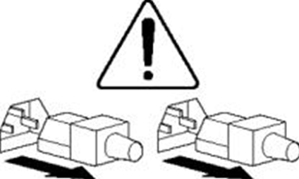
The server or component is heavy and requires more than one people to carry or move.
To avoid bodily injury or damage to hardware, do not move a heavy component alone. In addition, observe local occupational health and safety requirements and guidelines for manual material handling. |
|
|
|
The server is powered by multiple power supplies.
To avoid bodily injury from electrical shocks, make sure you disconnect all power supplies if you are performing offline servicing. |
About the server
The information in this document might differ from your product if it contains custom configuration options or features.
In this manual, the models of all components are simplified (for example, the prefix or suffix is deleted). Memory model DDR5-4800-32G-1Rx4 represents the following models: UN-DDR5-4800-32G-1Rx4-R, UN-DDR5-4800-32G-1Rx4-F, and UN-DDR5-4800-32G-1Rx4-S.
Figures in this document are for illustration only.
Server models and chassis view
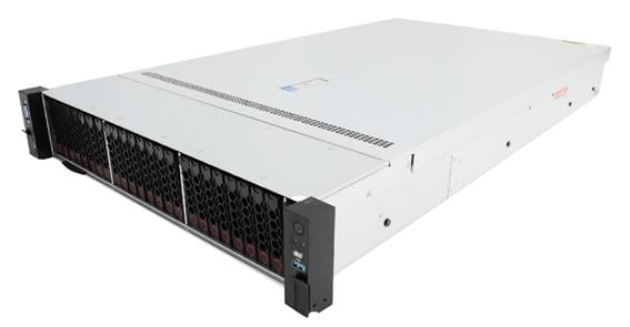
H3C UniServer R3950 G6 server is a rack server based on AMD EPYC 9004 series processors developed by New H3C. The server is 2U high and supports one processor. It features low power consumption, high reliability, strong scalability, and easy management and deployment. The server is suitable for virtualization, distributed storage, and data analysis.
Figure 1 shows the appearance of the server.
The servers come in the models listed in Table 2.
Table 2 R3950 G6 server models
|
Model |
Maximum drive configuration |
|
LFF |
12LFF drives at the front + 4LFF drives at the rear |
|
SFF |
25SFF drives at the front + 4SFF drives at the rear |
Server specifications
This section introduces the product specifications and technical parameters of the server.
Product specifications
|
Item |
Specifications |
|
Processors |
· 1 × AMD EPYC Genoa or Bergamo processors ¡ Up to 400 W power consumption per processor ¡ Up to 384 MB cache per processor ¡ Integrated memory controller, supports 12 memory channels ¡ Integrated PCIe controller, supports PCIe5.0 and 128 PCIe Lanes per processor ¡ Up to 4.1 GHz base frequency · For more information about processors, visit Server-Compatible Components Lookup Tool. |
|
Memory |
Up to 12 DIMMs Supports DDR5 DIMMs, up to 4800 MT/s, RDIMM, and a maximum of 1.5 TB capacity if one processor is installed |
|
Storage controllers |
· Embedded SATA/embedded NVMe storage controllers · High-performance storage controllers |
|
Integrated graphics |
The graphics chip (model AST2600) is integrated in the BMC management chip to provide a maximum resolution of 1920 × 1200@60Hz (32bpp), where: · 1920 × 1200: 1920 horizontal pixels and 1200 vertical pixels. · 60Hz: Screen refresh rate, 60 times per second. · 32bpp: Color depts. The higher the value, the more colors that can be displayed. The integrated graphics support a maximum resolution of 1920 × 1200 pixels only after you install a graphics driver that matches the operating system version. If the installed graphics driver does not match the operating system version, the integrated graphics support only the default resolution of the operating system. If you attach monitors to both the front and rear VGA connectors, only the monitor connected to the front VGA connector is available. |
|
Network connectors |
· 1 × embedded 1 Gbps HDM dedicated network port · Up to two OCP 3.0 network adapter connectors. OCP 3.0 network adapters support NCSI |
|
I/O connectors |
· 5 × USB connectors ¡ 4 × USB 3.0 connectors (one on the right chassis ear, two on the rear panel, and one on the system board) ¡ 1 × USB 2.0 connector (available on the left chassis ear only when the multifunctional rack mount kit is used) · 16 × SATA direct-out connectors (displayed as 4 × MCIO connectors)(reuse PCIe5.0) · 12 × built-in MCIO connectors (PCIe5.0 x8) · 1 × RJ-45 HDM dedicated network port (at the server rear) · 2 × VGA connectors (one on the front panel, and one available on the left chassis ear only when the multifunctional rack mount kit is used) · 1 × serial port (available only when the serial & DSD module is used) · 1 × HDM dedicated management port (available on the left chassis ear only when the multifunctional rack mount kit is used) |
|
Expansion slots |
8 × PCIe5.0 standard slots + 2 × OCP 3.0 network adapter slots |
|
Power supplies |
2 × hot-swappable power supplies, 1 + 1 redundancy |
Technical specifications
|
Category |
Item |
Specifications |
|
Physical parameters |
Dimensions (H × W × D) |
· Without a security bezel: 87.5 × 445.4 × 780 mm (3.44 × 17.54 × 30.71 in) · With a security bezel: 87.5 × 445.4 × 808 mm (3.44 × 17.54 × 31.81 in) |
|
Max. weight |
34 kg (74.96 lb) |
|
|
Power consumption |
The power consumption varies by configuration. For more information, visit H3C Server Power Consumption Evaluation. |
|
|
Environmental specifications |
Temperature |
Operating temperature: 5°C to 45°C (41°F to 113°F) NOTE: The maximum operating temperature requirement for the server might be lower than that stated, depending on the hardware configuration. For more information, see operating temperature specifications in appendix A. |
|
Storage temperature: –40°C to +70°C (–40°F to +158°F) |
||
|
· Operating humidity: 8% to 90% (non-condensing) · Storage humidity: 5% to 95% (non-condensing) |
||
|
· Operating altitude: –60 m to +3000 m (–196.85
ft to +9842.52 ft) · Storage altitude: -60m to 5000m (–196.85 ft to +16404.20 ft) |
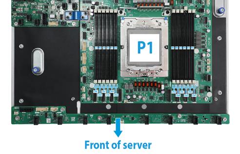
Components
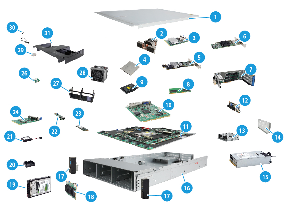
Figure 2 R3950 G6 server components
|
Item |
Description |
|
(1) Chassis access panel |
N/A |
|
(2) Processor heatsink |
Cools the processor. |
|
(3) OCP network adapter |
Network adapter installed onto the OCP network adapter connector on the system board. |
|
(4) Processor |
Integrates memory and PCIe controllers to provide data processing capabilities for the server. |
|
(5) Storage controller |
Provides RAID capability to SAS/SATA drives, including RAID configuration and RAID scale-up. It supports online upgrade of the controller firmware and remote configuration. |
|
(6) Standard PCIe network adapter |
Installed in a standard PCIe slot to provide network ports. |
|
(7) Riser card |
Provides PCIe slots. |
|
(8) Memory |
Stores computing data and data exchanged with external storage temporarily. The server supports DDR5 DIMMs. |
|
(9) Processor socket cover |
Installed over an empty processor socket to protect pins in the socket. |
|
(10) Server management module |
Provides I/O connectors and HDM out-of-band management features. |
|
(11) System board |
One of the most important parts of a server, on which multiple components are installed, such as processor, memory, and fan. It is integrated with basic server components, including the BIOS chip and PCIe connectors. |
|
(12) Rear drive backplane |
Provides power and data channels for drives at the server rear. |
|
(13) Rear drive cage |
Installed at the server rear to accommodate drives. |
|
(14) Riser card blank |
Installed on an empty PCIe riser connector to ensure good ventilation. |
|
(15) Power supply |
Supplies power to the server. The power supplies support hot swapping and 1+1 redundancy. |
|
(16) Chassis |
N/A |
|
(17) Chassis ears |
Attach the server to the rack. The right ear is integrated with the front I/O component, and the left ear is integrated with VGA connector, HDM dedicated management connector (Type-C), and USB 3.0 connector. |
|
(18) Front drive backplane |
Provides power and data channels for drives at the server front. |
|
(19) Drive |
Provides data storage space. Drives support hot swapping. Both SSDs and HDDs are supported and the supported drive interface types include SAS, SATA, M.2, and PCIe. |
|
(20) Supercapacitor holder |
Secures a supercapacitor in the chassis. |
|
(21) Supercapacitor |
Supplies power to the flash card on the power fail safeguard module, which enables the storage controller to back up data to the flash card for protection when power outage occurs. |
|
(22) SATA M.2 SSD expander module |
Provides M.2 SSD slots. |
|
(23) SATA M.2 SSD |
Provides data storage space for the server. |
|
(24) Serial & DSD module |
Provides one serial port and two SD card slots. |
|
(26) Encryption module |
Provides encryption services for the server to enhance data security. |
|
(27) Fan cage |
Accommodates fan modules. |
|
(28) Fan |
Helps server ventilation. Fans support hot swapping and N+1 redundancy. |
|
(29) System battery |
Supplies power to the system clock to ensure system time correctness. |
|
(30) Chassis open-alarm module |
Detects if the access panel is removed. The detection result can be displayed from the HDM Web interface. |
|
(31) Air baffle |
Provides ventilation aisles for processor heatsinks and memory modules and provides support for the supercapacitor. |
Front panel
Front panel view
Figure 3 8LFF front panel
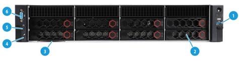
Table 3 8LFF front panel description
|
Item |
Description |
|
1 |
USB 3.0 connector |
|
2 |
Drive or LCD smart management module (optional) |
|
3 |
Serial label pull tab |
|
4 |
HDM dedicated management connector |
|
5 |
USB 2.0 connector |
|
6 |
VGA connector |
Figure 4 12LFF front panel
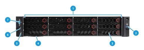
Table 4 12LFF front panel description
|
Item |
Description |
|
1 |
12LFF drives (optional) |
|
2 |
USB 3.0 connector |
|
3 |
Drive or LCD smart management module (optional) |
|
4 |
Serial label pull tab |
|
5 |
HDM dedicated management connector |
|
6 |
USB 2.0 connector |
|
7 |
VGA connector |
Figure 5 8SFF front panel
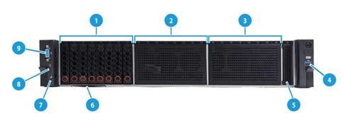
Table 5 8SFF front panel description
|
Item |
Description |
|
1 |
Bay 1: 8SFF drives (optional)* |
|
2 |
Bay 2: 8SFF drives (optional)* |
|
3 |
Bay 3: 8SFF drives (optional)* |
|
4 |
USB 3.0 connector |
|
5 |
LCD smart management module (optional) |
|
6 |
Serial label pull tab |
|
7 |
HDM dedicated management connector |
|
8 |
USB 2.0 connector |
|
9 |
VGA connector |
|
*: Drive types supported by the server vary by drive backplane configuration. For more information, see "Drive backplanes." |
|
Figure 6 25SFF front panel
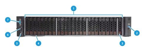
Table 6 25SFF front panel description
|
Item |
Description |
|
1 |
25SFF drives (optional) |
|
2 |
USB 3.0 connector |
|
3 |
Drive or LCD smart management module (optional) |
|
4 |
Serial label pull tab |
|
5 |
HDM dedicated management connector |
|
6 |
USB 2.0 connector |
|
7 |
VGA connector |
LEDs and buttons
Front panel LEDs and buttons
Figure 7 Front panel LEDs and buttons
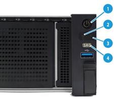
Table 7 LEDs and buttons on the front panel
|
Button/LED |
Status |
|
Power on/standby button and system power LED |
· Steady green—The system has started. · Flashing green (1 Hz)—The system is starting. · Steady amber—The system is in standby state. · Off—No power is present. Possible reasons: ¡ No power source is connected. ¡ No power supplies are present. ¡ The installed power supplies are faulty. ¡ The system power cords are not connected correctly. |
|
OCP 3.0 network adapter Ethernet port LED |
· Steady green—A link is present on a port of an OCP 3.0 network adapter. · Flashing green—A port on an OCP 3.0 network adapter is receiving or sending data. · Off—All ports on the OCP 3.0 network adapter are not in use. NOTE: The server supports two OCP3.0 network adapters and supports expansion of one more OCP3.0 network adapter. |
|
Health LED |
· Steady green—The system is operating correctly or a minor alarm is present. · Flashing green (4 Hz)—HDM is initializing. · Flashing amber (1 Hz)—A major alarm is present. · Flashing red (1 Hz)—A critical alarm is present. If a system alarm is present, log in to HDM to obtain more information about the system running status. |
|
UID button LED |
· Steady blue—UID LED is activated. The UID LED can be activated by using the following methods: ¡ Press the UID button LED. ¡ Activate the UID LED from HDM. · Flashing blue: ¡ 1 Hz—The firmware is being upgraded or HDM is performing out-of-band firmware update. Do not power off the server. ¡ 4 Hz—HDM is restarting. To restart HDM, press the UID button LED for eight seconds. · Off—UID LED is not activated. |
Intelligent security bezel LEDs and buttons
The LEDs of the intelligent security panel support linkage with server health status, reflecting the running status and health information of servers. This can accelerate on-site inspections and fault location. The LED effects of the intelligent security panel also support custom settings. The default LED effects are as shown in Table 8.
Figure 8 Intelligent security bezel LEDs and buttons
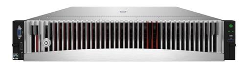
Table 8 LEDs and buttons on the intelligent security bezel
|
Phase |
LED state |
|
|
Standby |
Standby |
Steady white |
|
Startup |
POST phase |
White LEDs gradually light up from the middle to both sides, reflecting the percentage progress of the POST process |
|
POST finished |
white LEDs flow from the middle to both sides three times with a flowing effect |
|
|
Running |
Normal |
Breathing white (0.2Hz brightness transition), where the number of lit LEDs indicates the load level. As the overall load power consumption increases, the LEDs gradually light up from the middle and spread to both sides. The proportion of lit LEDs for different loads is as follows: · No load (below 10%) · Light load (10% to 50%) · Medium load (50% to 80%) · Heavy load (above 80%) |
|
Predictive alarming (only drive predictive alarming is supported) |
Breathing white (1 Hz brightness transition) |
|
|
Major alarm present |
Flashing amber (1 Hz) |
|
|
Critical alarm present (only power error is supported) |
Flashing red (1 Hz) |
|
|
Remote control |
System is being remotely managed or HDM is updating firmware through out-of-band (Do not power off the server) |
All flashing white (1 Hz) |
|
HDM restarting |
Some flashing white (1 Hz) |
|
Ports
Table 9 Ports on the front panel
|
Port |
Type |
Description |
|
VGA connector |
DB-15 |
Connects a display terminal, such as a monitor or KVM device. |
|
USB connector |
USB 3.0 |
Connects the following devices: · USB flash drive. · USB keyboard or mouse. · USB optical drive for operating system installation. |
|
HDM dedicated management connector |
Type-C |
Connects a Type-C to USB adapter cable, which connects to a USB Wi-Fi adapter or USB drive. |
Rear panel
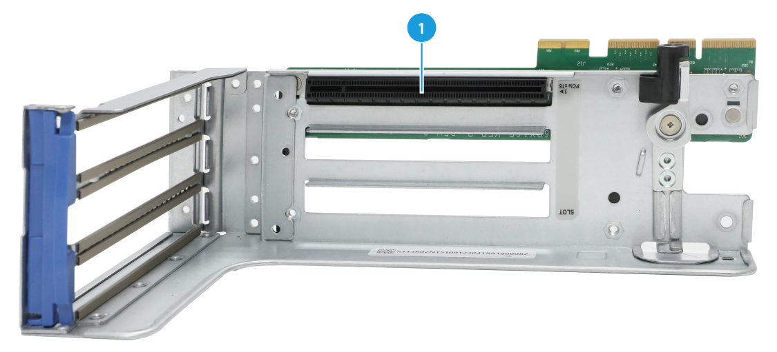
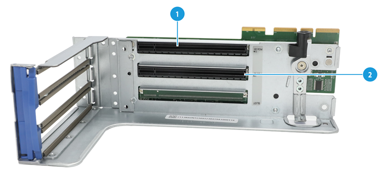
Rear panel view
Figure 9 Rear panel components
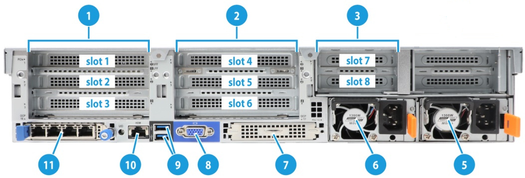
Table 10 Rear panel description
|
Description |
||
|
1 |
PCIe riser bay 1: PCIe slots 1 through 3 |
|
|
2 |
PCIe riser bay 2: PCIe slots 4 through 6 |
|
|
3 |
PCIe riser bay 3: PCIe slots 7 and 8 |
|
|
5 |
Power supply 2 |
|
|
6 |
Power supply 1 |
|
|
7 |
OCP 3.0 network adapter/Serial & DSD module (optional) |
|
|
8 |
VGA connector |
|
|
9 |
Two USB 3.0 connectors |
|
|
10 |
HDM dedicated network port (1Gbps, RJ-45, default IP address 192.168.1.2/24) |
|
|
11 |
OCP 3.0 network adapter (optional) |
|
|
For more information about serial & DSD modules, see "Serial & DSD module." |
||
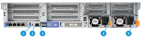
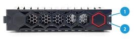
LEDs
|
(1) UID LED |
(2) Link LED of the Ethernet port |
|
(3) Activity LED of the Ethernet port |
(4) Power supply LED for power supply 1 |
|
(5) Power supply LED for power supply 2 |
|
Table 11 LEDs on the rear panel
|
LED |
Status |
|
UID LED |
· Steady blue—UID LED is activated. The UID LED can be activated by using the following methods: ¡ Press the UID button LED. ¡ Enable UID LED from HDM. · Flashing blue: ¡ 1 Hz—The firmware is being upgraded or HDM is performing out-of-band firmware update. Do not power off the server. ¡ 4 Hz—HDM is restarting. To restart HDM, press the UID button LED for 8 seconds. · Off—UID LED is not activated. |
|
Link LED of the Ethernet port |
· Steady green—A link is present on the port. · Off—No link is present on the port. |
|
Activity LED of the Ethernet port |
· Flashing green (1 Hz)—The port is receiving or sending data. · Off—The port is not receiving or sending data. |
|
Power supply LED |
· Steady green—The power supply is operating correctly or the server is in standby state. · Flashing green (0.33 Hz)—The power supply is in standby state and does not output power. · Flashing green (2 Hz)—The power supply is updating its firmware. · Steady amber—Either of the following conditions exists: ¡ The power supply is faulty. ¡ The power supply does not have power input, but another power supply has correct power input. · Flashing amber (1 Hz)—An alarm has occurred on the power supply. · Off—No power supplies have power input, which can be caused by an incorrect power cord connection or power source shutdown. |
Ports
Table 12 Ports on the rear panel
|
Port |
Type |
Description |
|
VGA connector |
DB-15 |
Connects a display terminal, such as a monitor or KVM device. |
|
BIOS port |
DB-9 |
The BIOS serial port is used for the following purposes: · Log in to the server when the remote network connection to the server has failed. · Establish a GSM modem or encryption lock connection. NOTE: The port is on the serial & DSD module. For more information, see "Serial & DSD module." |
|
USB connector |
USB 3.0 |
Connects the following devices: · USB flash drive. · USB keyboard or mouse. · USB optical drive for operating system installation. |
|
HDM dedicated network port |
RJ-45 |
Establishes a network connection to manage HDM from its Web interface. |
|
Power receptacle |
Standard single-phase |
Connects the power supply to the power source. |
System board
System board components
Figure 11 System board components
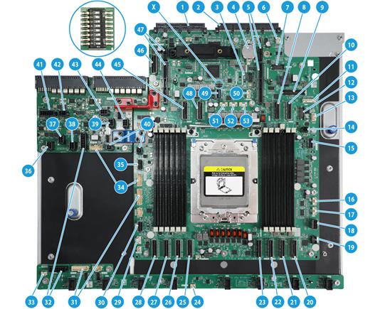
Table 13 System board components
|
No. |
Description |
Mark |
|
1 |
OCP 3.0 network adapter connector 2/DSD module connector |
OCP2&DSD&UART CARD |
|
2 |
Server management module connector |
BMC CON |
|
3 |
TPM/TCM connector |
TPM |
|
4 |
System battery |
N/A |
|
5 |
PCIe riser connector 1 |
RISER1 PCIe x16 |
|
6 |
Fan connector for OCP 3.0 network adapter 1 |
OCP1 FAN |
|
7 |
AMD HDT debugging connector |
AMD HDT |
|
8 |
MCIO connector C1-G1A |
C1-G1A |
|
9 |
AUX connector for OCP 3.0 network adapter 1 |
OCP1 AUX |
|
10 |
MCIO connector C1-G1C |
C1-G1C |
|
11 |
Drive backplane AUX connector 7 |
AUX 7 |
|
12 |
Front M.2 AUX connector |
M.2 AUX(FRONT) |
|
13 |
Drive backplane AUX connector 9 |
|
|
14 |
Power connector for OCP 3.0 network adapter 1 |
OCP1 PWR |
|
15 |
Front I/O connector |
RIGHT EAR |
|
16 |
Drive backplane AUX connector 3 |
AUX3 |
|
17 |
Drive backplane AUX connector 2 |
AUX2 |
|
18 |
LP SlimSAS connector C1-P4A |
C1-P4A |
|
19 |
LCD smart management module connector |
DIAG LCD |
|
20 |
MCIO connector C1-P1C |
C1-P1C |
|
21 |
MCIO connector C1-P1A |
C1-P1A |
|
22 |
MCIO connector C1-P0A |
C1-P0A |
|
23 |
MCIO connector C1-P0C |
C1-P0C |
|
24 |
Temperature sensor connector |
TEMP SENSE |
|
25 |
MCIO connector C1-P2C |
C1-P2C |
|
26 |
MCIO connector C1-P2A |
C1-P2A |
|
27 |
MCIO connector C1-P3A |
C1-P3A |
|
28 |
MCIO connector C1-P3C |
C1-P3C |
|
29 |
Drive backplane AUX connector 1 |
AUX1 |
|
30 |
Front VGA and USB 2.0 connector |
LEFT EAR |
|
31 |
Fan board AUX connector 1 |
FAN AUX1 |
|
32 |
Power connector for the fan board |
N/A |
|
33 |
Chassis-open alarm module connector |
INTRUDER |
|
34 |
Power board AUX connector |
N/A |
|
35 |
Drive backplane AUX connector 8 |
AUX8 |
|
36 |
Drive backplane power connector 1 |
PWR1 |
|
37 |
Drive backplane power connector 2 |
PWR2 |
|
38 |
Drive backplane power connector 3 |
PWR3 |
|
39 |
Drive backplane power connector 6 |
PWR6 |
|
40 |
Power board STBY power connector |
STBY PWR |
|
41 |
Drive backplane power connector 8 |
PWR8 |
|
42 |
Drive backplane power connector 7 |
PWR7 |
|
43 |
Drive backplane power connector 5 |
PWR5 |
|
44 |
Drive backplane power connector 4 |
PWR4 |
|
45 |
MCIO connector C1-G3A |
C1-G3A |
|
46 |
OCP 3.0 network adapter connector 2 (PCIe expansion connector) |
OCP2 x8 |
|
47 |
PCIe riser connector 2 |
RISER2 PCIe x16 |
|
48 |
MCIO connector C1-G3C |
C1-G3C |
|
49 |
Embedded USB3.0 connector |
INTER USB3.0 |
|
50 |
Liquid leakage detection module connector |
LEAKDET |
|
51 |
Drive backplane AUX connector 5 |
AUX5 |
|
52 |
Drive backplane AUX connector 6 |
AUX6 |
|
53 |
Drive backplane AUX connector 4 |
AUX4 |
|
X |
System maintenance switch |
N/A |
System maintenance switch
Figure 12 shows the system maintenance switch. Table 14 describes how to use the maintenance switch.
Figure 12 System maintenance switch
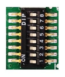
Table 14 System maintenance switch description
|
Item |
Description |
Remarks |
|
1 |
· Off (default)—HDM login requires the username and password of a valid HDM user account. · On—HDM login requires the default username and password. |
For security purposes, turn off the switch after you complete tasks with the default username and password as a best practice. |
|
5 |
· Off (default)—Normal server startup. · On—Restores the default BIOS settings. |
To restore the default BIOS settings: 1. Power off the server, and turn on the switch. 2. Power on the switch and wait for a minimum of 10 seconds. 3. Power off the server and then turn off the switch. 4. Start the server and verify that the POST screen prompts The CMOS defaults were loaded.
The server cannot start up when the switch is turned on. To avoid service data loss, stop running services and power off the server before turning on the switch. |
|
6 |
· Off (default)—Normal server startup. · On—Clears all passwords from the BIOS at server startup. |
If this switch is on, the server will clear all the passwords at each startup. Make sure you turn off the switch before the next server startup if you do not need to clear all the passwords. |
|
2, 3, 4, 7, and 8 |
Reserved for future use. |
N/A |
DIMM slots
A0, B0…H0, A1, B1…H1 represent the DIMM slot numbers, as shown in Figure 13. For installation guidelines of DIMMs, see "DIMM installation guidelines."
Figure 13 System board DIMM slot layout
HDDs and SSDs
Drive numbering
The server provides different drive numbering schemes for different drive configurations at the server front and rear, as shown in Figure 14 through Figure 19.
Figure 14 Drive numbering for front 25SFF drive configuration
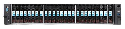
Figure 15 Drive numbering for front 12LFF drive configuration

Figure 16 Drive numbering for front 8LFF drive configuration
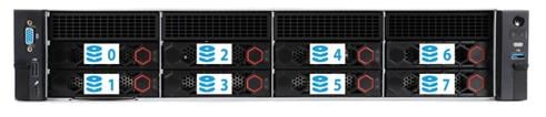
Figure 17 Drive numbering for rear 2LFF+4SFF drive configuration
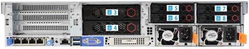
Figure 18 Drive numbering for rear 4LFF+2SFF drive configuration
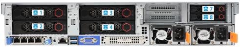
Figure 19 Drive numbering for rear 2SFF+2SFF+4SFF drive configuration

Drive LEDs
The server supports SAS/SATA drives and NVMe drives.
Figure 20 shows the location of the LEDs on a drive to indicate the drive status.
|
(1) Fault/UID LED |
(2) Present/Active LED |
To identify the status of a SAS or SATA drive, use Table 15. To identify the status of an NVMe drive, use Table 16.
Table 15 SAS/SATA drive LED description
|
Fault/UID LED status |
Present/Active LED status |
Description |
|
Flashing amber (0.5 Hz) |
Steady green/Flashing green (4.0 Hz) |
A drive failure is predicted. As a best practice, replace the drive before it fails. |
|
Steady amber |
Steady green/Flashing green (4.0 Hz) |
The drive is faulty. Replace the drive immediately. |
|
Steady blue |
Steady green/Flashing green (4.0 Hz) |
The drive is operating correctly and is selected by the RAID controller. |
|
Off |
Flashing green (4.0 Hz) |
The drive is performing a RAID migration or rebuilding, or the system is reading or writing data to the drive. |
|
Off |
Steady green |
The drive is present but no data is being read or written to the drive. |
|
Off |
Off |
The drive is not securely installed. |
Table 16 NVMe drive LED description
|
Fault/UID LED status |
Present/Active LED status |
Description |
|
Flashing amber (4 Hz) |
Off |
The drive is in hot insertion process. |
|
Steady amber |
Steady green/Flashing green (4.0 Hz) |
The drive is faulty. Replace the drive immediately. |
|
Steady blue |
Steady green/Flashing green (4.0 Hz) |
The drive is operating correctly and selected by the RAID controller. |
|
Off |
Flashing green (4.0 Hz) |
The drive is performing a RAID migration or rebuilding, or the system is reading or writing data to the drive. |
|
Off |
Steady green |
The drive is present but no data is being read or written to the drive. |
|
Off |
Off |
The drive is not securely installed. |
Drive backplanes
The server supports the following types of drive backplanes:
· SAS/SATA drive backplanes—Support only SAS/SATA drives.
· UniBay drive backplanes—Support both SAS/SATA and NVMe drives. You must connect both SAS/SATA and NVMe data cables. The number of supported drives varies by drive cabling.
· X SAS/SATA+Y UniBay drive backplanes—Support SAS/SATA drives in all slots and support NVMe drives in certain slots.
¡ X: Number of slots supporting only SAS/SATA drives.
¡ Y: Number of slots supporting both SAS/SATA and NVMe drives.
For UniBay drive backplanes and X SAS/SATA+Y UniBay drive backplanes:
· The two drive types are supported only when both SAS/SATA and NVMe data cables are connected.
· The number of supported SAS/SATA drives and the number of supported NVMe drives vary by cable connection.
Front 8SFF SAS/SATA drive backplane
The PCA-BP-8SFF-2U-G6 8SFF SAS/SATA drive backplane can be installed at the server front to support eight 2.5-inch SAS/SATA drives.
Figure 21 8SFF SAS/SATA drive backplane
|
(1) x8 SlimSAS connector (SAS PORT1) |
(2) AUX connector (AUX) |
|
(3) Power connector (PWR) |
|
Front 8SFF UniBay drive backplane
The PCA-BP-8UniBay-2U-G6 8SFF UniBay drive backplane can be installed at the server front to support eight 2.5-inch SAS/SATA/NVMe drives.
Figure 22 8SFF UniBay drive backplane
|
(1) x8 SlimSAS connector (SAS PORT) |
(2) AUX ( AUX) |
|
(3) MCIO connector B3/B4 (PCIe5.0 x8)(NVMe B3/B4) |
|
|
(4) Power connector (POWER) |
|
|
(5) MCIO connector B1/B2 (PCIe5.0 x8)(NVMe B1/B2) |
|
|
(6) MCIO connector A3/A4 (PCIe5.0 x8)(NVMe A3/A4) |
|
|
(7) MCIO connector A1/A2 (PCIe5.0 x8)(NVMe A1/A2) |
|
|
PCIe5.0 x8 description: · PCIe5.0: Fifth-generation signal speed. · x8: Bus bandwidth. |
|
Front 8LFF SAS/SATA drive backplane
The PCA-BP-8LFF-2U-G6 8LFF SAS/SATA drive backplane can be installed at the server front to support eight 3.5-inch SAS/SATA drives.
Figure 23 8LFF SAS/SATA drive backplane
|
(1) x8 Mini-SAS-HD connector (SAS PORT) |
(2) Power connector (PWR) |
|
(3) AUX connector (AUX) |
|
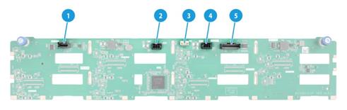
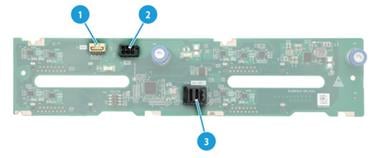
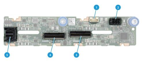
Front 12LFF SAS/SATA drive backplane
The PCA-BP-12LFF-2U-G6 12LFF SAS/SATA drive backplane can be installed at the server front to support twelve 3.5-inch SAS/SATA drives.
Figure 24 12LFF SAS/SATA drive backplane
|
(1) x4 SlimSAS connector (SAS PORT 2), managing the last four SAS/SATA drives on the backplane |
|
|
(2) Power connector 2 (PWR 2) |
(3) AUX connector (AUX) |
|
(4) Power connector 1 (PWR 1) |
|
|
(5) x8 SlimSAS connector (SAS PORT 1), managing the first eight SAS/SATA drives on the backplane |
|
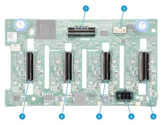
Front 8SAS/SATA+4UniBay drive backplane
The PCA-BP-12LFF-4NVMe-2U-G6 12LFF drive backplane can be installed at the server front to support twelve 3.5-inch SAS/SATA/NVMe drives, including eight SAS/SATA drives and four SAS/SATA/NVMe drives.
Figure 25 8SAS/SATA+4UniBay drive backplane
|
(1) MCIO connector A3 (PCIe5.0 x4)(NVMe-A3), supporting NVMe drive 9 |
|
|
(2) x4 SlimSAS connector (SAS PORT 2), managing the last four SAS/SATA drives on the backplane |
|
|
(3) Power connector 2 (PWR 2) |
(4) AUX connector 1(AUX 1) |
|
(5) Power connector 1 (PWR 1) |
|
|
(6) x8 SlimSAS connector (SAS PORT 1), managing the first eight SAS/SATA drives on the backplane |
|
|
(7) MCIO connector A4 (PCIe5.0 x4)(NVMe-A4), supporting NVMe drive 8 |
|
|
(8) MCIO connector A1/A2 (PCIe5.0 x8)(NVMe-A1/A2), supporting NVMe drives 10 and 11 |
|
|
For more information about drive numbering, see Figure 15. PCIe5.0 x8 description: · PCIe5.0: Fifth-generation signal speed. · x8: Bus bandwidth. |
|
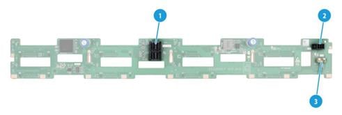
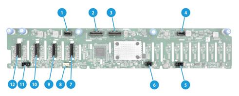
Front 4SAS/SATA+8UniBay drive backplane
The PCA-BP-12LFF-EXP-2U-G6 12LFF drive backplane can be installed at the server front to support twelve 3.5-inch SAS/SATA/NVMe drives, including four SAS/SATA drives and eight SAS/SATA/NVMe drives. The drive backplane integrates an Expander chip to manage 12 SAS/SATA drives through an x8 SlimSAS connector. The drive backplane also provides three downlink interfaces to connect to other drive backplanes and support more drives.
Figure 26 4SAS/SATA+8UniBay drive backplane
|
(1) x8 SlimSAS uplink interface (SAS PORT), managing all drives on the backplane |
|
|
(2) x4 SlimSAS downlink interface 3 (SAS EXP3) |
(3) Power connector 2 (PWR2) |
|
(4) MCIO connector B1/B2 (PCIe5.0 x8)(NVMe-B1/B2), supporting NVMe drives 6 and 7 |
|
|
(5) Power connector 1 (PWR1) |
(6) x8 SlimSAS downlink interface 2 (SAS EXP2) |
|
(7) x4 SlimSAS downlink interface 1 (SAS EXP1) |
(8) AUX connector (AUX) |
|
(9) MCIO connector B3/B4 (PCIe5.0 x8)(NVMe B3/B4), supporting NVMe drives 4 and 5 |
|
|
(10) MCIO connector A3/A4 (PCIe5.0 x8)(NVMe A3/A4), supporting NVMe drives 8 and 9 |
|
|
(11) MCIO connector A1/A2 (PCIe5.0 x8)(NVMe A1/A2), supporting NVMe drives 10 and 11 |
|
|
For more information about drive numbering, see Figure 15. PCIe5.0 x8 description: · PCIe5.0: Fifth-generation signal speed. · x8: Bus bandwidth. |
|
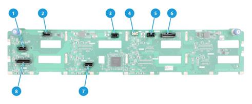
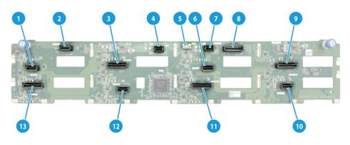
Front 12LFF UniBay drive backplane
The PCA-BP-12LFF-UniBay-2U-G6 12LFF UniBay drive backplane can be installed at the server front to support twelve 3.5-inch SAS/SATA/NVMe drives.
Figure 27 12LFF UniBay drive backplane
|
(1) MCIO connector A3 (PCIe5.0 x4)(NVMe-A3) |
|
|
(2) x4 SlimSAS connector (SAS PORT 2), managing the last four SAS/SATA drives on the backplane |
|
|
(3) MCIO connector B1/B2 (PCIe5.0 x8)(NVMe-B1/B2) |
(4) Power connector 2 (PWR 2) |
|
(5) AUX connector 1 (AUX 1) |
(6) MCIO connector C1 (PCIe5.0 x4)(NVMe-C1) |
|
(7) Power connector 1 (PWR 1) |
|
|
(8) x8 SlimSAS connector (SAS PORT 1), managing the first eight SAS/SATA drives on the backplane |
|
|
(9) MCIO connector C3/C4 (PCIe5.0 x8)(NVMe-C3/C4) |
|
|
(10) MCIO connector C2 (PCIe5.0 x4)( NVMe-C2) |
|
|
(11) MCIO connector B3/B4 (PCIe5.0 x8)(NVMe-B3/B4) |
|
|
(12) MCIO connector A4 (PCIe5.0 x4)(NVMe-A4) |
|
|
(13) MCIO connector A1/A2 (PCIe5.0 x8)(NVMe-A1/A2) |
|
|
PCIe5.0 x8 description: · PCIe5.0: Fifth-generation signal speed. · x8: Bus bandwidth. |
|
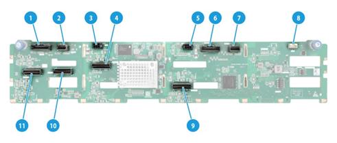
Front 17SAS/SATA+8UniBay drive backplane
The PCA-BP-25SFF-2U-G6 25SFF drive backplane can be installed at the server front to support twenty-five 2.5-inch SAS/SATA/NVMe drives, including 17 SAS/SATA drives and 8 SAS/SATA/NVMe drives. The drive backplane can use an x8 SlimSAS connector to manage 25 SAS/SATA drives. The drive backplane also integrates an Expander chip and three downlink interfaces to connect to other drive backplanes and support more drives.
Figure 28 17SAS/SATA+8UniBay drive backplane
|
(1) x4 SlimSAS downlink interface 3 (SAS EXP 3) |
|
|
(2) x8 SlimSAS uplink interface (SAS PORT), managing all drives on the backplane |
|
|
(3) x8 SlimSAS downlink interface 2 (SAS EXP 2) |
(4) x4 SlimSAS downlink interface 1 (SAS EXP 1) |
|
(5) Power connector 1 (PWR 1) |
(6) Power connector 2 (PWR 2) |
|
(7) MCIO connector 4 (PCIe5.0 x8)(NVMe 4), supporting NVMe drives 17 and 18 |
|
|
(8) AUX connector (AUX) |
|
|
(9) MCIO connector 3 (PCIe5.0 x8)(NVMe 3), supporting NVMe drives 19 and 20 |
|
|
(10) MCIO connector 2 (PCIe5.0 x8)(NVMe 2), supporting NVMe drives 21 and 22 |
|
|
(11) Power connector 3 (PWR 3) |
|
|
(12) MCIO connector 1 (PCIe5.0 x8)(NVMe 1), supporting NVMe drives 23 and 24 |
|
|
For more information about drive numbering, see Figure 14. PCIe5.0 x8 description: · PCIe5.0: Fifth-generation signal speed. · x8: Bus bandwidth. |
|
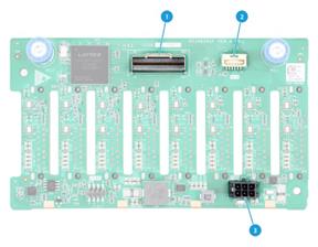
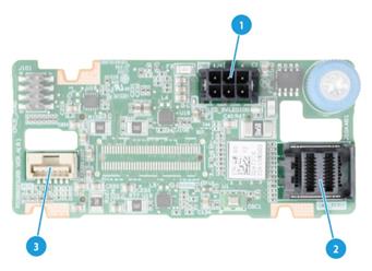
Rear 2LFF SAS/SATA drive backplane
The PCA-BP-2LFF-2U-G6 2LFF SAS/SATA drive backplane is installed at the server rear to support two 3.5-inch SAS/SATA drives.
Figure 29 2LFF SAS/SATA drive backplane
|
(1) x4 Mini-SAS-HD connector (SAS PORT1) |
(2) AUX connector (AUX1) |
|
(3) Power connector (PWR1) |
|
Rear 4LFF SAS/SATA drive backplane
The PCA-BP-4LFF-2U-G6 4LFF SAS/SATA drive backplane is installed at the server rear to support four 3.5-inch SAS/SATA drives.
Figure 30 4LFF SAS/SATA drive backplane
|
(1) AUX connector (AUX1) |
(2) Power connector (PWR1) |
|
(3) x4 Mini-SAS-HD connector (SAS PORT1) |
|
Rear 2SFF SAS/SATA drive backplane
The PCA-BP-2SFF-2U-G6 2SFF SAS/SATA drive backplane is installed at the server rear to support two 2.5-inch SAS/SATA drives.
Figure 31 2SFF SAS/SATA drive backplane
|
(1) Power connector (PWR) |
(2) x4 Mini-SAS-HD connector (SAS PORT) |
|
(3) AUX connector (AUX) |
|
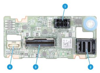
Rear 2SFF UniBay drive backplane
The PCA-BP-2SFF-2UniBay-2U-G6 2SFF UniBay drive backplane is installed at the server rear to support two 2.5-inch SAS/SATA/NVMe drives.
Figure 32 2SFF UniBay drive backplane
|
(1) Power connector (PWR) |
(2) x4 Mini-SAS-HD connector (SAS PORT) |
|
(3) SlimSAS connector (PCIe4.0 x8)(NVME) |
(4) AUX connector (AUX) |
|
PCIe4.0 x8 description: · PCIe4.0: Fifth-generation signal speed. · x8: Bus bandwidth. |
|
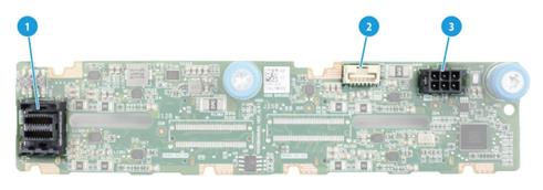
Rear 4SFF SAS/SATA drive backplane
The PCA-BP-4SFF-2U-G6 4SFF SAS/SATA drive backplane is installed at the server rear to support four 2.5-inch SAS/SATA drives.
Figure 33 4SFF SAS/SATA drive backplane
|
(1) x4 Mini-SAS-HD connector (SAS PORT) |
(2) AUX connector (AUX) |
|
(3) Power connector (PWR) |
|
Rear 4SFF UniBay drive backplane
The PCA-BP-4SFF-4UniBay-2U-G6 4SFF UniBay drive backplane is installed at the server rear to support four 2.5-inch SAS/SATA/NVMe drives.
Figure 34 4SFF UniBay drive backplane
|
(1) AUX connector (AUX) |
(2) Power connector (PWR) |
|
(3) MCIO connector B1/B2 (PCIe5.0 x8) (NVME-B1/B2) |
|
|
(4) MCIO connector B3/B4 (PCIe5.0 x8) (NVME-B3/B4) |
|
|
(5) x4 Mini-SAS-HD connector (SAS PORT) |
|
|
PCIe5.0 x8 description: · PCIe5.0: Fifth-generation signal speed. · x8: Bus bandwidth. |
|
Riser cards
The server supports the following riser cards:
· RC-3FHFL-2U-G6
· RC-3FHHL-2U-G6
· RC-1FHHL-2U-G6
· RC-2FHHL-2U-G6
· Riser 4 assembly module (accommodating two FHFL PCIe modules)
· Riser 3 assembly module (accommodating two FHFL PCIe modules)
For more information about riser cards and their installation guidelines, see "Riser cards and PCIe modules."
RC-3FHFL-2U-G6
Figure 35 RC-3FHFL-2U-G6 (1)
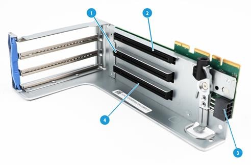
Figure 36 RC-3FHFL-2U-G6 (2)
|
(1) PCIe5.0 x16 (16,8,4,2,1) slot 2/5 |
(2) PCIe5.0 x16 (16,8,4,2,1) slot 3/6 |
|
(3) GPU module power connector |
(4) PCIe5.0 x16 (16,8,4,2,1) slot 1/4* |
|
(5) MCIO connector 2-C |
(6) MCIO connector 2-A |
|
(7) MCIO connector 1-A |
(8) MCIO connector 1-C |
|
PCIe5.0 x16 (16,8,4,2,1) description: · PCIe5.0: Fifth-generation signal speed. · x16: Connector bandwidth. · (16,8,4,2,1): Compatible bus bandwidth, including x16, x8, x4, x2, and x1. |
|
|
|
NOTE: slot 1/4: When the riser card is installed in PCIe riser bay 1, this slot corresponds to PCIe slot 1. When the riser card is installed in PCIe riser bay 2, this slot corresponds to PCIe slot 4. This rule applies to all the other PCIe slots. For information about PCIe slots, see "Rear panel view." |
RC-3FHHL-2U-G6
Figure 37 RC-3FHHL-2U-G6 (1)
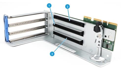
Figure 38 RC-3FHHL-2U-G6 (2)
|
(1) PCIe5.0 x16 (8,4,2,1) slot 2/5 |
(2) PCIe5.0 x16 (8,4,2,1) slot 3/6 |
|
(3) PCIe5.0 x16 (16,8,4,2,1) slot 1/4* |
(4) MCIO connector 1-A |
|
(5) MCIO connector 1-C |
|
|
PCIe5.0 x16 (16,8,4,2,1) description: · PCIe5.0: Fifth-generation signal speed. · x16: Connector bandwidth. · (16,8,4,2,1): Compatible bus bandwidth, including x16, x8, x4, x2, and x1. |
|
|
|
NOTE: slot 1/4: When the riser card is installed in PCIe riser bay 1, this slot corresponds to PCIe slot 1. When the riser card is installed in PCIe riser bay 2, this slot corresponds to PCIe slot 4. This rule applies to all the other PCIe slots. For information about PCIe slots, see "Rear panel view." |
RC-1FHHL-2U-G6
Figure 39 RC-1FHHL-2U-G6
|
(1) PCIe5.0 x16 slot 3/6* |
|
|
NOTE: slot 3/6: When the riser card is installed in PCIe riser bay 1, this slot corresponds to PCIe slot 3. When the riser card is installed in PCIe riser bay 2, this slot corresponds to PCIe slot 6. This rule applies to all the other PCIe slots. For information about PCIe slots, see "Rear panel view." |
RC-2FHHL-2U-G6
Figure 40 RC-2FHHL-2U-G6
|
(1) PCIe5.0 x16 slot 5/6* |
(2) PCIe5.0 x16 slot 2/3 |
|
|
NOTE: slot 5/6: When the riser card is installed in PCIe riser bay 1, this slot corresponds to PCIe slot 5. When the riser card is installed in PCIe riser bay 2, this slot corresponds to PCIe slot 6. This rule applies to all the other PCIe slots. For information about PCIe slots, see "Rear panel view." |
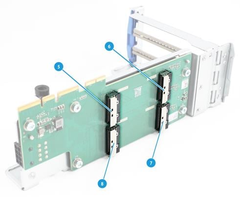
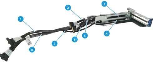
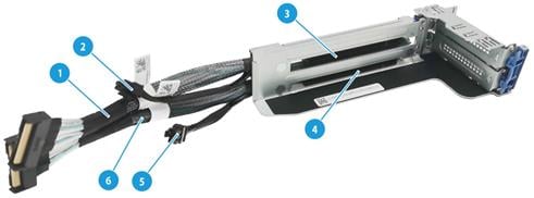
Riser 4 assembly module (accommodating two FHFL PCIe modules)
This riser 4 assembly module is as shown in Figure 41.
Figure 41 Riser 4 assembly module (accommodating two FHFL PCIe modules)
|
1 |
PCIe interface cable S2 from slot 9 (connected to connector C1-P3C on the system board) |
|
2 |
PCIe interface cable S1 from slot 10 (connected to connector C1-G3A on the system board) |
|
3 |
PCIe5.0 x16 (16,8,4,2,1) in slot 10 |
|
4 |
PCIe5.0 x16 (16,8,4,2,1) in slot 9 |
|
5 |
PCIe interface cable S2 from slot 10 (connected to connector C1-G3C on the system board) |
|
6 |
Power connector S3 from slot 10 (connected to connector PWR6 on the system board) |
|
7 |
Power connector S3 from slot 9 (connected to connector PWR7 on the system board) |
|
8 |
PCIe interface cable S1 from slot 9 (connected to connector C1-P3A on the system board) |
|
PCIe5.0 x16 (16, 8,4,2,1) description: · PCIe5.0: Fifth-generation signal speed. · x16: Connector bandwidth. · (16,8,4,2,1): Compatible bus bandwidth, including x16, x8, x4, x2, and x1. |
|
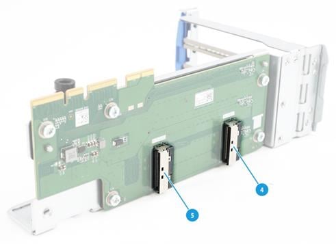
Riser 3 assembly module (accommodating two HHHL PCIe modules)
This riser 3 assembly module is as shown in Figure 42.
Figure 42 Riser 3 assembly module (accommodating two HHHL PCIe modules)
|
1 |
PCIe interface cable S1 from slot 8 (connected to connector C2-P3C on the system board) |
|
2 |
Power connector S2 from slot 8 (connected to connector PWR7 on the system board) |
|
3 |
PCIe5.0 x8 (8,4,2,1) in slot 8 |
|
4 |
PCIe5.0 x8 (8,4,2,1) in slot 7 |
|
5 |
Power connector S2 from slot 7 (connected to connector PWR6 on the system board) |
|
6 |
PCIe interface cable S1 from slot 7 (connected to connector C2-P3A on the system board) |
|
PCIe5.0 x8 (8,4,2,1) description: · PCIe5.0: Fifth-generation signal speed. · x8: Connector bandwidth. · (8,4,2,1): Compatible bus bandwidth, including x8, x4, x2, and x1. |
|
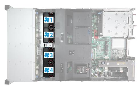
Fan modules
The server supports four hot swappable fan modules. The server supports N+1 fan module redundancy. Figure 43 shows the layout of the fan modules in the chassis.
The server can automatically adjust the fan speed based on the actual system temperature. The speed policy is designed to optimize system cooling while minimizing noise levels, achieving an optimal balance between the two.
LCD smart management module
An LCD smart management module displays basic server information, operating status, and fault information, and provides diagnostics and troubleshooting capabilities. You can locate and troubleshoot component failures by using the LCD module in conjunction with the event logs generated in HDM.
For more information, see the LCD smart management module user guide.
Figure 44 LCD smart management module
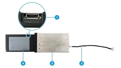
Table 17 LCD smart management module components
|
No. |
Item |
Description |
|
1 |
Mini-USB connector |
Used for upgrading the firmware of the LCD module. |
|
2 |
LCD module cable |
Connects the LCD module to the system board of the server. For information about the LCD smart management module connector on the system board, see "System board components." |
|
3 |
LCD module shell |
Protects and secures the LCD screen. |
|
4 |
LCD screen |
Displays basic server information, operating status, and fault information. |
|
To install an LCD smart management module, prepare a compatible cable. For more information, see "Connecting the LCD smart management module cable." |
||
B/D/F information
You can obtain B/D/F information by using one of the following methods:
· BIOS log—Search the dumpiio keyword in the BIOS log.
· UEFI shell—Execute the pci command. For information about how to execute the command, execute the help pci command.
· Operating system—The obtaining method varies by OS.
¡ For Linux, execute the lspci command.
If Linux does not support the lspci command by default, obtain and install the pci-utils package from the yum repository.
¡ For Windows, install the pciutils package, and then execute the lspci command.
¡ For VMware, execute the lspci command.
Component installation guidelines
Processor
· The server supports one processor.
· To avoid damage to a processor or the system board, only H3C authorized or professional server engineers can install, replace, or remove a processor.
· The pins in the processor sockets are very fragile and prone to damage. Install a protective cover if a processor socket is empty.
· For the server to operate correctly, make sure the processor is in position. For more information about the processor location, see "System board components."
· To prevent static electricity from damaging the electronic components, wear an ESD wrist strap and make sure it makes good skin contact and is reliably grounded.
· To prevent burns due to high temperatures of the processor heatsink or processor liquid cooling module during the disassembly process, make sure proper thermal protection is taken before performing any operations.
DIMMs
The server supports DDR5 DIMMs.
Basic DIMM concepts
DDR
DDR5 DIMMs can perform parity check on addresses and the DDR5 DIMMs cannot protect data from getting lost in case of unexpected system power outage.
Rank
The number of ranks is usually 1, 2, 4, or 8, generally abbreviated as 1R/SR, 2R, 4R, 8R, or single-rank, dual-rank, quad-rank, or 8-rank.
· A 1R DIMM has a set of DIMM chips that will be accessed when data is written to or read from the DIMM.
· A 2R DIMM is equivalent to a module containing two 1R DIMMs, but only one rank can be accessed at a time.
· A 4R DIMM is equivalent to a module containing two 2R DIMMs, but only one rank can be accessed at a time.
· An 8R DIMM is equivalent to a module containing two 4R DIMMs, but only one rank can be accessed at a time.
When writing or reading data in a DIMM, the server memory control subsystem will select the correct rank from the DIMM.
DIMM specifications
To determine the rank classification of a DIMM, use the label attached to the DIMM, as shown in Figure 45.
Figure 45 DDR DIMM rank classification label
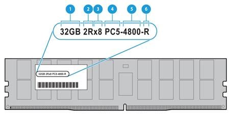
Table 18 DIMM rank classification label description
|
Callout |
Description |
Remarks |
|
1 |
Capacity |
Options include: · 32GB. · 64 GB. |
|
2 |
Number of ranks |
Options include: · 1R—One rank (Single-Rank). · 2R—Two ranks (Dual-Rank). · 4R—Four ranks (Quad-Rank). · 8R—Eight ranks (8-Rank). |
|
3 |
Data width |
Options include: · ×4—4 bits. · ×8—8 bits. |
|
4 |
DIMM generation |
DDR5 |
|
5 |
Data rate |
4800B, indicating 4800 MHz. |
|
6 |
DIMM type |
R, indicating RDIMM. |
Installation guidelines
The server supports one processor. The processor supports 12 channels, and each channel supports one DIMM, that is, one processor supports 12 DIMMs.
DIMM and processor compatibility
Table 19 describes the DIMM and processor compatibility.
Table 19 DIMM and processor compatibility
|
Processor type |
Processor-compatible memory type@frequency |
Remarks |
|
AMD Genoa EYPC |
DDR5 @4800MHz |
N/A |
|
AMD Bergamo EYPC |
DDR5 @4800MHz |
N/A |
Memory operating frequency
|
|
NOTE: To obtain the memory frequency and maximum memory frequency supported by a specific processor, use the component compatibility lookup tool at http://www.h3c.com/en/home/qr/default.htm?id=66. You can query the memory frequency by selecting Memory Module and query the maximum supported memory frequency by selecting Processor. |
The actual operating memory frequency is equal to the lesser of the memory frequency or the maximum memory frequency supported by the processors. For example, if the memory frequency is 4400 MHz and the maximum memory frequency supported by processors is 4800 MHz, the actual operating memory frequency is 4400 MHz.
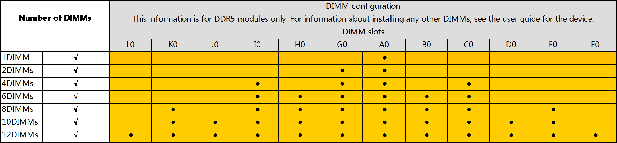
DIMM installation guidelines
· As a best practice, install DDR5 DIMMs that have the same product code and DIMM specification (type, capacity, rank, and frequency). For information about DIMM product codes, use the component compatibility lookup tool at http://www.h3c.com/en/home/qr/default.htm?id=66. To install components or replace faulty DIMMs of other specifications, contact Technical Support.
· If the processor is installed populate DIMMs as shown in Figure 46.
Figure 46 DIMM population scheme for the processor
SAS/SATA drives
|
|
IMPORTANT: Using a drive in multiple RAID arrays complicates maintenance and affects RAID performance. As a best practice for HDD drives to be recognized by the system, when you hot swap HDD drives, replace them one by one, and make sure two drives are replaced with an interval of a minimum of 30 seconds. |
· The drives are hot swappable.
· As a best practice, install drives that do not contain RAID information.
· To avoid RAID performance degradation and RAID creation failures, make sure all drives in the RAID are the same type (HDDs or SSDs) and have the same connector type (SAS or SATA).
· For efficient use of storage, use drives that have the same capacity to build a RAID. If the drives have different capacities, the lowest capacity is used across all drives in the RAID.
NVMe drives
Support for hot swapping of NVMe drives depends on the operating system.
If an operating system supports hot swapping of NVMe drives, follow these guidelines:
· Insert NVMe drives steadily without pauses to prevent the operating system from being stuck or restarted.
· Do not hot swap multiple NVMe drives at the same time. As a best practice, hot swap NVMe drives one after another at intervals longer than 30 seconds. After the operating system identifies the first NVMe drive, you can hot swap the next drive. If you insert multiple NVMe drives simultaneously, the system might fail to identify the drives.
M.2 SSD drives
M.2 SSD drives can be installed in a server through an M.2 SSD expander module.
Front SATA/NVMe M.2 SSD drives
· The front M.2 SSD expander module is installed between the drive backplane and the fan modules at the front of the chassis. It supports the installation of SATA and NVMe M.2 SSD drives, with a maximum configuration of two drives. The expander module is connected to the system board through data cables. For more information about cabling, see "Connecting cables for the front M.2 SSD expander module."
· As a best practice, use SATA M.2 SSD drives for installing the operating system.
Figure 47 Front M.2 SSD expander module (front view)
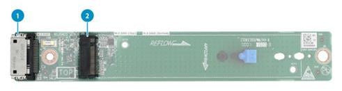
|
(1) Data cable connector |
(2) M.2 SSD drive slot 1 |
Figure 48 Front M.2 SSD expander module (rear view)
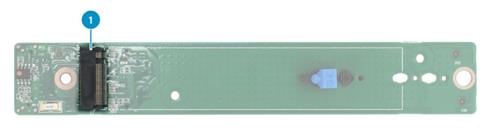
|
(1) M.2 SSD drive slot 2 |
Server management module
The server management module is installed on the system board to provide I/O connectors and HDM out-of-band features for the server.
Figure 49 Server management module

|
(1) VGA connector |
(2) Two USB 3.0 connectors |
|
(3) HDM dedicated network interface |
(4) UID LED |
|
(5) HDM serial port |
(6) iFIST module |
|
(7) NCSI connector |
|
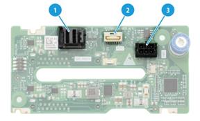
Serial & DSD module
The serial & DSD module is installed in the slot on the server rear panel. The module provides two SD slots and forms RAID 1 by default.
|
|
NOTE: To avoid SD card storage waste, install two SD cards with the same capacity. |
Figure 50 Serial & DSD module
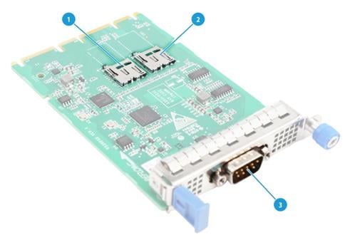
Table 20 Component description
|
Item |
Description |
|
1 |
SD card slot 1 |
|
2 |
SD card slot 2 |
|
3 |
Serial port |
Riser cards and PCIe modules
Typically, the PCIe modules are available in the following standard form factors:
· LP—Low profile.
· FHHL—Full height and half length.
· FHFL—Full height and full length.
· HHHL—Half height and half length.
· HHFL—Half height and full length.
Restrictions and guidelines
For information about PCI riser connectors on the system board, see "System board components." For information about PCIe slots on riser cards, see "Riser cards."
You can install a PCIe module in a PCIe slot for a larger-sized PCIe module. For example, an LP PCIe module can be installed in a slot for an FHFL PCIe module.
A PCIe slot can supply power to the installed PCIe module if the maximum power consumption of the module does not exceed 75 W. If the maximum power consumption exceeds 75 W, a power cord is required.
The description for PCIe5.0 x16 (16,8,4,2,1) is as follows:
· PCIe5.0: Fifth-generation signal speed.
· x16: Connector bandwidth.
· (16,8,4,2,1): Compatible bus bandwidth, including x16, x8, x4, x2, and x1.
For an x8 MCIO connector, x8 indicates the bus bandwidth.
Riser card and PCIe module compatibility
For the riser card and PCIe module compatibility, see Table 21 through Table 24. For the riser assembly module and PCIe module compatibility, see "Riser cards."
Table 21 Riser card and PCIe module compatibility (1)
|
Riser card model |
Riser card location |
PCIe slots on a riser card |
PCIe slot or connector description |
PCIe module for PCIe slot or connector |
PCIe slot power capability |
|
RC-3FHFL-2U-G6 |
PCIe riser connector 1 |
Slots 1 through 3 |
PCIe5.0 x16 (16,8,4,2,1) |
FHFL |
75 W |
|
SLOT 1-A |
x8 MCIO connector |
Connected to MCIO connector C1-G1A on the system board, providing an x16 PCIe link for slot 1 with x8 MCIO connector SLOT 1-C |
N/A |
||
|
SLOT 1-C |
x8 MCIO connector |
Connected to MCIO connector C1-G1C on the system board, providing an x16 PCIe link for slot 1 with x8 MCIO connector SLOT 1-A |
N/A |
||
|
SLOT 2-A |
x8 MCIO connector |
Connected to MCIO connector C1-P1A on the system board, providing an x16 PCIe link for slot 2 with x8 MCIO connector SLOT 2-C |
N/A |
||
|
SLOT 2-C |
x8 MCIO connector |
Connected to MCIO connector C1-P1C on the system board, providing an x16 PCIe link for slot 2 with another x8 MCIO connector SLOT 2-A |
N/A |
||
|
PCIe riser connector 2 |
Slots 4 through 6 |
PCIe5.0 x16 (16,8,4,2,1) |
FHFL |
75 W |
|
|
SLOT 1-A |
x8 MCIO connector |
Connected to MCIO connector C1-G3A, providing an x16 PCIe link for slot 4 with x8 MCIO connector SLOT 1-C |
N/A |
||
|
SLOT 1-C |
x8 MCIO connector |
Connected to MCIO connector C1-G3C on the system board, providing an x16 PCIe link for slot 4 with x8 MCIO connector SLOT 1-A |
N/A |
||
|
SLOT 2-A |
x8 MCIO connector |
Connected to MCIO connector C2-P2A on the system board, providing an x16 PCIe link for slot 5 with x8 MCIO connector SLOT 2-C |
N/A |
||
|
SLOT 2-C |
x8 MCIO connector |
Connected to MCIO connector C1-P2C on the system board, providing an x16 PCIe link for slot 5 with x8 MCIO connector SLOT 2-A |
N/A |
Table 22 Riser card and PCIe module compatibility (2)
|
Riser card model |
Riser card location |
PCIe slots on a riser card |
PCIe slot or connector description |
PCIe module for PCIe slot or connector |
PCIe slot power capability |
|
RC-3FHHL-2U-G6 |
PCIe riser connector 1 |
Slot 1 |
PCIe5.0 x16 (16,8,4,2,1) |
FHHL |
75 W |
|
Slot 2/3 |
PCIe5.0 x16 (8,4,2,1) |
FHHL |
75 W |
||
|
SLOT 1-A |
x8 MCIO connector |
Connected to MCIO connector C1-P1A on the system board, providing an x16 PCIe link for slot 1 with x8 MCIO connector SLOT 1-C |
N/A |
||
|
SLOT 1-C |
x8 MCIO connector |
Connected to MCIO connector C1-P1C on the system board, providing an x16 PCIe link for slot 1 with x8 MCIO connector SLOT 1-A |
N/A |
||
|
PCIe riser connector 2 |
Slot 4 |
PCIe5.0 x16 (16,8,4,2,1) |
FHHL |
75 W |
|
|
Slot 5/6 |
PCIe5.0 x16 (8,4,2,1) |
FHHL |
75 W |
||
|
SLOT 1-A |
x8 MCIO connector |
Connected to MCIO connector C1-P2A, providing an x16 PCIe link for slot 1 with x8 MCIO connector SLOT 1-C. |
N/A |
||
|
SLOT 1-C |
x8 MCIO connector |
Connected to MCIO connector C1-P2C on the system board, providing an x16 PCIe link for slot 1 with x8 MCIO connector SLOT 1-A |
N/A |
Table 23 Riser card and PCIe module compatibility (3)
|
Riser card model |
Riser card location |
PCIe slots on a riser card |
PCIe slot or connector description |
PCIe module for PCIe slot or connector |
PCIe slot power capability |
|
RC-1FHHL-2U-G6 |
PCIe riser connector 1 |
slot 4 |
PCIe4.0 x8 |
FHHFL |
75 W |
|
PCIe riser connector 2 |
slot 6 |
PCIe4.0 x8 |
FHHL |
75 W |
Table 24 Riser card and PCIe module compatibility (4)
|
Riser card model |
Riser card location |
PCIe slots on a riser card |
PCIe slot or connector description |
PCIe module for PCIe slot or connector |
PCIe slot power capability |
|
RC-2FHHL-2U-G6 |
PCIe riser connector 1 |
slot 2/3 |
PCIe4.0 x8 |
FHHL |
75 W |
|
PCIe riser connector 2 |
slot 5/6 |
PCIe4.0 x8 |
FHHL |
75 W |
Storage controllers and power fail safeguard modules
About storage controllers
The server supports the following types of storage controllers:
· Embedded VROC controller—Embedded in the server and does not require installation.
· Standard storage controller—Comes in a standard PCIe form factor and typically requires a riser card for installation.
Power fail safeguard module
For some storage controllers, you can order a power fail safeguard module to prevent data loss when power outage occurs.
A power fail safeguard module provides a flash card and a supercapacitor. When a system power failure occurs, this supercapacitor can provide power for a minimum of 20 seconds. During this interval, the storage controller transfers data from DDR memory to the flash card, where the data remains indefinitely or until the controller retrieves the data.
|
|
NOTE: The supercapacitor might have a low charge after the power fail safeguard module is installed or after the server is powered up. If the system displays that the supercapacitor has low charge, no action is required. The system will charge the supercapacitor automatically. You can view the status of the supercapacitor from the BIOS. |
A supercapacitor has a lifespan of 3 to 5 years. If the lifespan of a supercapacitor expires, a supercapacitor exception might occur. The system notifies users of supercapacitor exceptions by using the following methods:
· For a PMC storage controller, the status of the flash card will become Abnormal_status code. You can check the status code to identify the exception. For more information, see HDM2 online help.
· For an LSI storage controller, the status of the flash card of the power fail safeguard module will become Abnormal.
You can also review log messages from HDM2 to identify supercapacitor exceptions. For more information, see HDM2 online help.
For the power fail safeguard module to take effect, replace the supercapacitor before its lifespan expires.
|
|
IMPORTANT: After the supercapacitor replacement, verify that cache related settings are enabled for logical drives. For more information, see HDM2 online help. |
Installation guidelines
You can install one or multiple standard storage controllers. When you install standard storage controllers, follow these restrictions and guidelines:
· Make sure the standard storage controllers are of the same vendor (PMC or LSI). For information about the available storage controllers and their vendors, use the component compatibility lookup tool at http://www.h3c.com/en/home/qr/default.htm?id=66.
· If the drives are installed only at the server front, install storage controllers to different riser cards. The controller in a lower-numbered slot is connected to the drive backplane for the lower-numbered drive carriers and the controller in a higher-numbered slot to the drive backplane for the higher-numbered drive carriers. For more information about the drive carrier locations, see "Front panel view."
· If the drives are installed at both the server front and server rear, install storage controllers to one riser card. The controller in a lower-numbered slot is connected to the front drive backplane and the controller in a higher-numbered slot to the rear drive backplane. For information about slot locations, see the rear panel view in "Rear panel view."
Use Table 25 to identify the supercapacitor available for a storage controller.
Table 25 Standard storage controller and supercapacitor compatibility matrix
|
Standard storage controller |
Supercapacitor |
Supercapacitor installation location |
|
RAID-LSI-9560-LP-8i-4GB |
BAT-LSI-G3-A |
In the supercapacitor container on the air baffle |
|
RAID-LSI-9560-LP-16i |
||
|
RAID-P460-B4 |
BAT-PMC-G3-2U |
|
|
HBA-LSI-9500-LP-8i |
Not supported |
Not supported |
Network adapters
An OCP network adapter can be installed only to an OCP3.0 network adapter connector on the system board. For information about OCP network adapter connectors on the system board, see "System board components."
To install a standard PCIe network adapter, a riser card is required. For more information about riser card and PCIe module compatibility, see "Riser cards and PCIe modules."
GPU modules
For information about configuration guides for the power cords of GPU modules, contact Technical Support.
To install FHFL dual-width GPU modules, install them to slots as shown in Table 26, as a best practice, and follow these guidelines:
· Install GPU modules in PCIe slots with x16 bus bandwidth.
· If the number of GPU modules is equal to or smaller than 3, install the GPU modules to riser cards.
To install FHFL single-width GPU modules, install them to slots as shown in Table 27, as a best practice, and follow these guidelines:
· Install GPU modules in PCIe slots with x16 bus bandwidth.
· If the number of GPU modules is equal to or smaller than 3, install one GPU to each riser card.
· If the number of GPU modules is equal to 4, install two RC-3FHFL-2U-G6 riser cards and install two GPU modules to each riser card as a best practice.
· If the number of GPU modules is equal to 5, install two RC-3FHFL-2U-G6 riser cards and install two GPU modules to each riser card, and install one GPU module to the riser 4 assembly module.
To install HHHL single-width GPU modules, install them to slots as shown in Table 28 as a best practice. If the number of GPU modules is equal to 8, you can install GPU modules to PCIe slots with x8 bus bandwidth. In other cases, install GPU modules to PCIe slots with x16 bus bandwidth.
Table 26 FHFL dual-width GPU installation guidelines
|
Number of GPUs |
Recommended GPU installation locations |
|
1 |
Slot 5 |
|
2 |
Slots 2 and 5 |
|
3 |
Slots 2, 5, and 9 |
Table 27 FHFL single-width GPU installation guidelines
|
Number of GPUs |
Recommended GPU installation locations |
|
1 |
Slot 5 |
|
2 |
Slots 2 and 5 |
|
3 |
Slots 2, 5, and 9 |
|
4 |
Slots 1, 2, 4, and 5 |
|
5 |
Slots 1, 2, 4, 5, and 9 |
Table 28 HHHL GPU installation guidelines
|
Number of GPUs |
Recommended GPU installation locations |
|
1 |
slot 5 |
|
2 |
slot 2, 5 |
|
3 |
slot 2, 5, 9 |
|
4 |
slot 1, 2, 4, 5 |
|
5 |
slot 1, 2, 4, 5, 9 |
|
6 |
slot 1, 2, 3, 4, 5, 6 |
|
7 |
slot 1, 2, 3, 4, 5, 6, 9 |
|
8 |
slot 1, 2, 3, 4, 5, 6, 7, 8 |
Power supplies
|
|
NOTE: For more information about the specifications of power supplies, see the power supply manuals for them. |
The power supplies installed on the server must be the same model. If they differ in model, HDM would raise an alarm.
The power supplies are hot swappable.
To avoid damage to hardware, use only H3C approved power supplies.
The server supports 1+1 power supply redundancy.
The system provides an overtemperature mechanism for power supplies. The power supplies automatically turn off when they encounter an overtemperature situation and automatically turn on when the overtemperature situation is removed.
Fan modules
The fan modules support hot swapping and N+1 redundancy.
The server must be fully configured with fan modules of the same model.
The server supports both single-rotor FAN-8038-2U-G6 fan module and dual-rotor FAN-8056-2U-G6 fan module. When any of the following conditions are met, you must install the FAN-8056-2U-G6 fan module:
· The 12LFF drive backplane, 25SFF drive backplane, two 8SFF UniBay drive backplanes, or three 8SFF UniBay drive backplanes are installed along with processors with a TDP of more than 360 W are all installed.
· The processor with a TDP of more than 360 W is installed and the 4LFF drive backplane is installed at the server rear.
· The A2 GPU modules are installed.
· The MCX623106AN-CDAT or MCX623436AN-CDAB OCP3.0 network adapter is installed.
· When you configure an OCP3.0 network adapter with a bandwidth of 100 Gb/s or higher on OCP1, it is necessary to configure an OCP fan module.
Installing or removing the server
This section describes the steps for installing and removing the server.
Installation planning
Before installing the server, plan and prepare the physical environment for optimal operation, including space, ventilation, temperature, humidity, cleanliness, altitude, and grounding.
Rack requirements
The server is 2U high and has a depth of 780 mm (30.71 in). The rack for installing the server must meet the following requirements:
· A standard 19-inch rack.
· A minimum of 1200 mm (47.24 in) in depth as a best practice. For installation limits for different rack depth, see Table 29. As a best practice to avoid installation failures, contact Technical Support to perform onsite survey before the installation.
· A clearance of more than 50 mm (1.97 in) between the rack front posts and the front rack door.
· Table 29Figure 51 shows the installation recommendations for a 1200 mm deep rack.
Table 29 Installation requirements for different rack depths
|
Rack depth |
Installation requirements |
|
1000 mm (39.37 in) |
· The H3C cable management arm (CMA) is not supported. · A clearance of 60 mm (2.36 in) is reserved from the server rear to the rear rack door for cabling. · The slide rails and PDUs might hinder each other. Perform onsite survey to determine the PDU installation location and the proper PDUs. If the PDUs hinder the installation and movement of the slide rails anyway, use other methods to support the server, a tray for example. |
|
1100 mm (43.31 in) |
Make sure the CMA does not hinder PDU installation at the server rear before installing the CMA. If the CMA hinders PDU installation, use a deeper rack or change the installation locations of PDUs. |
|
1200 mm (47.24 in) |
Make sure the CMA does not hinder PDU installation or cabling. If the CMA hinders PDU installation or cabling, change the installation locations of PDUs. |
Figure 51 Installation recommendations for a 1200 mm deep rack (top view)
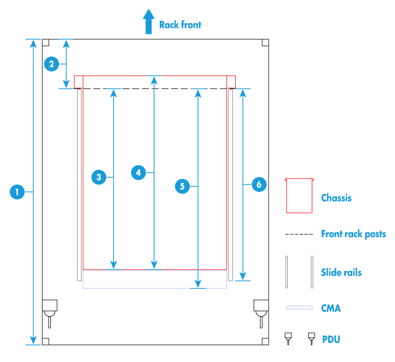
|
(1) 1200 mm (47.24 in) rack depth |
|
(2) A minimum of 50 mm (1.97 in) between the front rack posts and the front rack door |
|
(3) 780 mm (30.71 in) between the front rack posts and the rear of the chassis, including power supply handles at the server rear (not shown in the figure) |
|
(4) 800 mm (31.50 in) server depth, including chassis ears |
|
(5) 960 mm (37.80 in) between the front rack posts and the CMA |
|
(6) 860 mm (33.86 in) between the front rack posts and the rear ends of the slide rails |
Airflow direction of the server
Figure 52 Airflow direction of the server
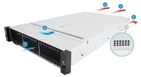
|
(1) and (2) Directions of the airflow into the chassis and power supplies |
|
(3) Directions of the airflow out of the power supplies |
|
(4) and (5) Direction of the airflow out of the chassis |
Temperature and humidity requirements
To ensure correct operation of the server, make sure the room temperature and humidity meet the requirements as described in "Technical specifications."
Equipment room height requirements
To ensure correct operation of the server, make sure the equipment room height meets the requirements as described in "Technical specifications."
Corrosive gas concentration requirements
About corrosive gas
Corrosive gases can accelerate corrosion and aging of metal components and even cause server failure. Table 30 describes common corrosive gases and their sources.
Table 30 Common corrosive gases and their sources
|
Corrosive gas |
Sources |
|
Hydrogen sulfide (H2S) |
Geothermal emissions, microbiological activities, fossil fuel processing, wood pulping, sewage treatment, combustion of fossil fuel, auto emissions, ore smelting, and sulfuric acid manufacture. |
|
Sulfur dioxide (SO2) and sulfur trioxide (SO3) |
Combustion of fossil fuel, auto emissions, ore smelting, sulfuric acid manufacture, and tobacco smoke. |
|
Sulphur (S) |
Foundries and sulfur manufacture. |
|
Hydrogen Fluoride (HF) |
Fertilizer manufacture, aluminum manufacture, ceramics manufacture, steel manufacture, electronics device manufacture, and fossil fuel. |
|
Nitrogen Oxide (NOx) |
Automobile emissions, fossil fuel combustion, microbes, and chemical industry. |
|
Ammonia (NH3) |
Microbes, sewage, fertilizer manufacture, geothermal steam, refrigeration equipment, cleaning products, and reproduction (blueprint) machines. |
|
Carbonic oxide (CO) |
Combustion, automobile emissions, microbes, trees, and wood pulping. |
|
Chlorine (Cl2) and chlorine dioxide (ClO2) |
Chlorine manufacture, aluminum manufacture, papermills, refuse decomposition, and cleaning products. |
|
Hydrochloric acid (HCl) |
Automobile emissions, combustion, oceanic processes, and polymer combustion. |
|
Hydrobromic acid (HBr) and hydroiodic acid (HI) |
Automobile emissions. |
|
Ozone (O3) |
Atmospheric photochemical processes mainly involving nitrogen oxides and oxygenated hydrocarbons, automotive emissions, and electrostatic filters. |
|
Hydrocarbons (CnHn) |
Automobile emissions, fossil fuel processing, tobacco smoke, water treatment, microbes, paper mill, and many other sources, both natural and industrial. |
Requirements of corrosive gas concentration vary by server model. For information about the requirements, see the installation guide of the server.
Requirements for the data center equipment room
As a best practice, make sure the corrosive gas concentration for the data center equipment room meets the requirements of severity level G1 of ANSI/ISA 71.04-1985. The rate of copper corrosion product thickness growth must be less than 300 Å/month, and the rate of silver corrosion product thickness growth must be less than 200 Å/month. Angstrom (Å) is a metric unit of length equal to one ten-billionth of a meter.
To meet the copper and silver corrosion rates stated in severity level G1, make sure the corrosive gases in the equipment room do not exceed the concentration limits as shown in Table 31.
Table 31 Corrosive gas concentration limits in the data center equipment room
|
Corrosive gas |
Concentration (ppb) |
|
H2S |
< 3 |
|
SO2, SO3 |
< 10 |
|
Cl2 |
< 1 |
|
NOx |
< 50 |
|
HF |
< 1 |
|
NH3 |
< 500 |
|
O3 |
< 2 |
|
|
NOTE: · Part per billion (ppb) is a concentration unit. 1 ppb represents a volume-to-volume ratio of 1 to 100000000. · The concentration limits are calculated based on the reaction results of the gases in the equipment room with a relative humidity less than 50%. If the relative humidity of the equipment room increases by 10%, the severity level of ANSI/ISA 71.04-1985 to be meet must also increase by 1. |
Requirements of corrosive gas concentration vary by server model. For more information about the requirements, see the installation guide of the server.
Requirements for the non-data center equipment room
The corrosive gas concentration for the non-data center equipment room must meet the requirements of class 3C2 of IEC 60721-3-3:2002, as shown in Table 32.
Table 32 Corrosive gas concentration limits in the non-data center equipment room
|
Gas |
Average concentration (mg/m3) |
Maximum concentration (mg/m3) |
|
SO2 |
0.3 |
1.0 |
|
H2S |
0.1 |
0.5 |
|
Cl2 |
0.1 |
0.3 |
|
HCI |
0.1 |
0.5 |
|
HF |
0.01 |
0.03 |
|
NH3 |
1.0 |
3.0 |
|
O3 |
0.05 |
0.1 |
|
NOX |
0.5 |
1.0 |
|
|
CAUTION: As a best practice, control the corrosive gas concentrations in the equipment room at their average values. Make sure the corrosive gas concentrations do not exceed 30 minutes per day at their maximum values. |
Requirements of corrosive gas concentration vary by server model. For information about the requirements, see the installation guide of the server.
Guidelines for controlling corrosive gases
To control corrosive gases, follow these guidelines:
· As a best practice, do not build the equipment room in a place with a high concentration of corrosive gases.
· Make sure the equipment room is not connected to sewer, sewage, vertical shaft, or septic tank pipelines and keep it far away from these pipelines. The air inlet of the equipment room must be away from such pollution sources.
· Use environmentally friendly materials to decorate the equipment room. Avoid using organic materials that contains harmful gases, such as sulfur or chlorine-containing insulation cottons, rubber mats, sound-proof cottons, and avoid using plasterboards with high sulfur concentration.
· Place fuel (diesel or gasoline) engines separately. Do not place them in the same equipment room with the device. Make sure the exhausted air of the engines will not flow into the equipment room or towards the air inlet of the air conditioners.
· Place batteries separately. Do not place them in the same room with the device.
· Employ a professional company to monitor and control corrosive gases in the equipment room regularly.
Cleanliness requirements
Requirements of dust particle concentration vary by server model. For information about the requirements, see the installation guide of the server.
Requirements for the data center equipment room
The concentration of dust participles in the equipment room must meet the ISO 8 cleanroom standard defined by ISO 14644-1, as described in Table 33. Make sure no zinc whiskers are in the equipment room.
Table 33 Dust particle concentration limit in the equipment room
|
Particle diameter |
Concentration limit |
Remarks |
|
≥ 5 µm |
≤ 29300 particles/m3 |
Make sure no zinc whiskers are in the equipment room. |
|
≥ 1 µm |
≤ 832000 particles/m3 |
|
|
≥ 0.5 µm |
≤ 3520000 particles/m3 |
Requirements of dust particle concentration vary by server model. For information about the requirements, see the installation guide of the server.
Requirements for the non-data center equipment room
The concentration of dust participles (particle diameter ≥ 0.5 µm) must meet the requirement of the GB 50174-2017 standard, which is less than 17600000 particles/m3.
Requirements of dust particle concentration vary by server model. For information about the requirements, see the installation guide of the server.
Guidelines for controlling cleanliness
To maintain cleanliness in the equipment room, follow these guidelines:
· Keep the equipment room away from pollution sources and do not smoke or eat in the equipment room.
· Use double-layer glass in windows and seal doors and windows with dust-proof rubber strips.
· Use dustproof materials for floors, walls, and ceilings and use matt coating that does not produce powders.
· Keep the equipment room clean and clean the air filters of the rack regularly.
· Wear ESD clothing and shoe covers before entering the equipment room. Keep the ESD clothing and shoe covers clean and replace them frequently.
Grounding requirements
Correctly connecting the server grounding cable is crucial to lightning protection, anti-interference, and ESD prevention. The server can be grounded through the grounding wire of the power supply system and no external grounding cable is required.
Storage requirements
Follow these guidelines to store storage media:
· As a best practice, do not store an HDD for 6 months or more without powering on and using it.
· As a best practice, do not store an SSD, M.2 SSD, or SD card for 3 months or more without powering on and using it. Long unused time increases data loss risks.
· To store the server chassis, or an HDD and SSD for 3 months or more, power on it every 3 months and run it for a minimum of 2 hours each time. For information about powering on and powering off the server, see "Powering on and powering off the server."
Installation tools
Table 34 lists the tools that you might use during installation.
|
Picture |
Name |
Description |
|
|
T25 Torx screwdriver |
Installs or removes screws inside chassis ears. A flat-head screwdriver can also be used for this purpose. |
|
T30 Torx screwdriver |
Installs or removes captive screws on processor heatsinks. |
|
|
T15 Torx screwdriver (shipped with the server) |
Installs or removes screws on the system board. |
|
|
T10 Torx screwdriver (shipped with the server) |
Installs or removes screws on riser cards. |
|
|
Flat-head screwdriver |
Installs or removes captive screws inside multifunctional rack mount ears or replaces system batteries. |
|
|
Phillips screwdriver |
Installs or removes screws on drive carriers. |
|
|
|
Cage nut insertion/extraction tool |
Inserts or extracts the cage nuts in rack posts. |
|
|
Diagonal pliers |
Clips insulating sleeves. |
|
|
Utility knife |
Removes the server's external packaging. |
|
|
Tape measure |
Measures distance. |
|
|
Multimeter |
Measures resistance and voltage. |
|
|
ESD wrist strap |
Prevents ESD when you operate the server. |
|
|
Antistatic gloves |
Prevents ESD when you operate the server. |
|
|
Antistatic clothing |
Prevents ESD when you operate the server. |
|
|
Ladder |
Supports high-place operations. |
|
|
Interface cable (such as an Ethernet cable or optical fiber) |
Connects the server to an external network. |
|
|
Serial console cable |
Connects the serial connector on the server to a monitor for troubleshooting. |
|
|
Type-C to USB adapter cable, used to connect USB Wi-Fi module or USB flash drive |
· When using an external third-party USB Wi-Fi module, you can access the HDM interface through the HDM Mobile client on a mobile device. · When connecting a USB flash drive, you can download SDS logs to the USB drive from the HDM interface. NOTE: Support for USB Wi-Fi modules depends on the server model. |
|
|
Monitor |
Displays the output from the server. |
|
|
Temperature and humidity meter |
Displays current temperature and humidity. |
|
|
Oscilloscope |
Displays the variation of voltage over time in waveforms. |


Installing the server
Installing rails
Install the inner rails to the server and the outer rails to the rack. For information about installing the rails, see the document shipped with the rails.
Rack-mounting the server
1. Slide the server into the rack. For more information about how to slide the server into the rack, see the installation guide for the rails.
Figure 53 Rack-mounting the server
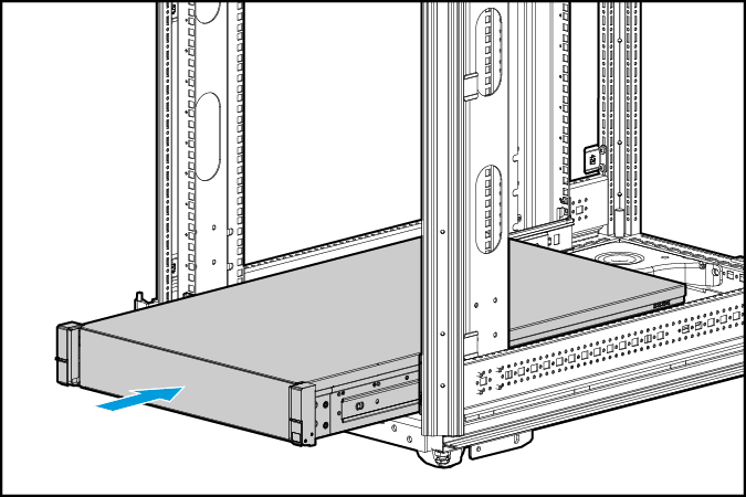
2. Secure the server.
a. Push the server until the multifunctional rack mount ears are flush against the rack front posts, as shown by callout 1 in Figure 54.
b. Unlock the latches of the multifunctional rack mount ears, as shown by callout 2 in Figure 54.
c. Fasten the captive screws inside the chassis ears and lock the latches, as shown by callout 3 in Figure 54.
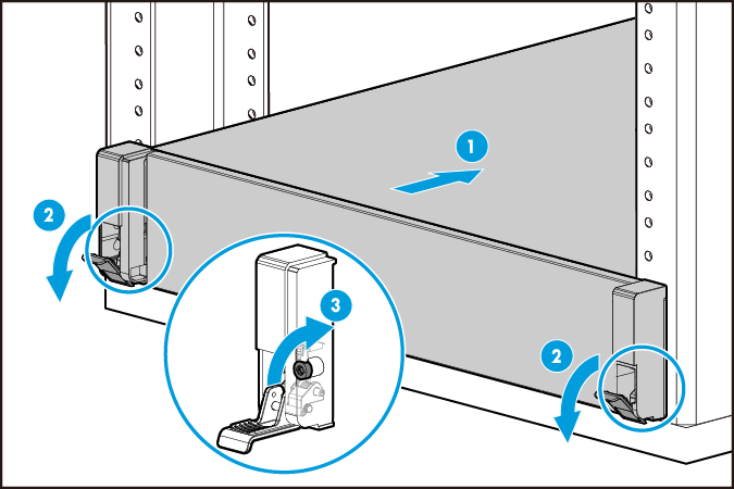
Installing cable management brackets
Install cable management brackets if the server is shipped with cable management brackets. For information about how to install cable management brackets, see the installation guide shipped with the brackets.
Connecting external cables
Connecting a mouse, keyboard, and monitor
About this task
|
|
NOTE: The operating systems supported by the server come with a built-in VGA driver by default. If a higher display resolution is required, update the built-in VGA driver. To obtain the new VGA driver, access the H3C official website, select Software Download > Servers, and enter "VGA" in the search box. |
The server provides two DB15 VGA connectors for connecting a monitor. One is on the front panel and the other is on the rear panel.
The server is not shipped with a standard PS2 mouse and keyboard. To connect a PS2 mouse and keyboard, you must prepare a USB-to-PS2 adapter.
Procedure
1. Connect one plug of a VGA cable to a VGA connector on the server, and fasten the screws on the plug.
Figure 55 Connecting a VGA cable

2. Connect the other plug of the VGA cable to the VGA connector on the monitor, and fasten the screws on the plug.
3. Connect the mouse and keyboard.
¡ For a USB mouse and keyboard, directly connect the USB connectors of the mouse and keyboard to the USB connectors on the server.
¡ For a PS2 mouse and keyboard, insert the USB connector of the USB-to-PS2 adapter to a USB connector on the server. Then, insert the PS2 connectors of the mouse and keyboard into the PS2 receptacles of the adapter.
Figure 56 Connecting a PS2 mouse and keyboard by using a USB-to-PS2 adapter
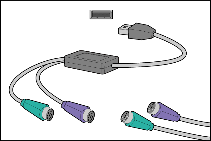
Connecting an Ethernet cable
About this task
Perform this task before you set up a network environment or log in to the HDM management interface through the HDM network port to manage the server.
Procedure
1. Determine the network port on the server.
¡ To connect the server to the external network, use the Ethernet port on the network adapter.
¡ To log in to the HDM management interface, use the HDM dedicated network port. For the location of the HDM dedicated network port, see "Rear panel view."
If the server is configured with an OCP network adapter, you can also use the HDM shared network port on the OCP network adapter to log in to the HDM management interface. For the location of the OCP network adapter, see "Rear panel view."
2. Determine type of the Ethernet cable.
Verify the connectivity of the cable by using a link tester.
If you are replacing the Ethernet cable, make sure the new cable is the same type or compatible with the old cable.
3. Label the Ethernet cable by filling in the names and numbers of the server and the peer device on the label.
As a best practice, use labels of the same kind for all cables.
If you are replacing the Ethernet cable, label the new cable with the same number as the number of the old cable.
4. Connect one end of the Ethernet cable to the network port on the server and the other end to the peer device.
Figure 57 Connecting an Ethernet cable
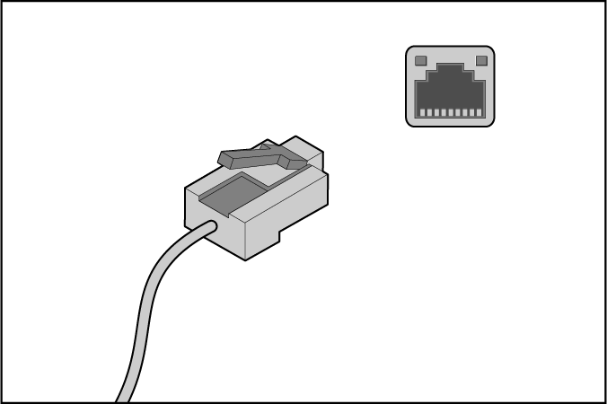
5. Verify network connectivity.
After powering on the server, use the ping command to test the network connectivity. If the connection between the server and the peer device fails, verify that the Ethernet cable is securely connected.
6. Secure the Ethernet cable. For information about how to secure cables, see "Securing cables."
Connecting the power cord
Guidelines
|
|
WARNING! To avoid damage to the equipment or even bodily injury, use the power cord that ships with the server. |
Before connecting the power cord, make sure the server and components are installed correctly.
Procedure
1. Insert the power cord plug into the power receptacle of a power supply at the rear panel, as shown in Figure 58.
Figure 58 Connecting the power cord
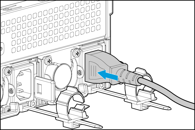
2. Connect the other end of the power cord to the power source, for example, the power strip on the rack.
3. Secure the power cord to avoid unexpected disconnection of the power cord.
Multiple types of wire fasteners can be used for securing the power cord. In this procedure, a cable clamp is used.
a. If the cable clamp is positioned too near the power cord that it blocks the power cord plug connection, press down the tab on the cable mount and slide the clip backward.
Figure 59 Sliding the cable clamp backward
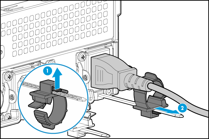
b. Open the cable clamp, place the power cord through the opening in the cable clamp, and then close the cable clamp, as shown by callouts 1, 2, 3, and 4 in Figure 60.
Figure 60 Securing the AC power cord
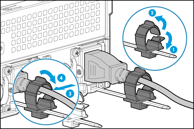
c. Slide the cable clamp forward until it is flush against the edge of the power cord plug, as shown in Figure 61.
Figure 61 Sliding the cable clamp forward
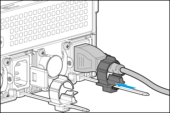
Securing cables
Securing cables to cable management brackets
For information about how to secure cables to cable management brackets, see the installation guide shipped with the brackets.
Securing cables to slide rails by using cable straps
You can secure cables to either left slide rails or right slide rails. As a best practice for cable management, secure cables to left slide rails.
When multiple cable straps are used in the same rack, stagger the strap location, so that the straps are adjacent to each other when viewed from top to bottom. This positioning will enable the slide rails to slide easily in and out of the rack.
To secure cables to slide rails by using cable straps:
1. Hold the cables against a slide rail.
2. Wrap the strap around the slide rail and loop the end of the cable strap through the buckle.
3. Dress the cable strap to ensure that the extra length and buckle part of the strap are facing outside of the slide rail.
Figure 62 Securing cables to a slide rail
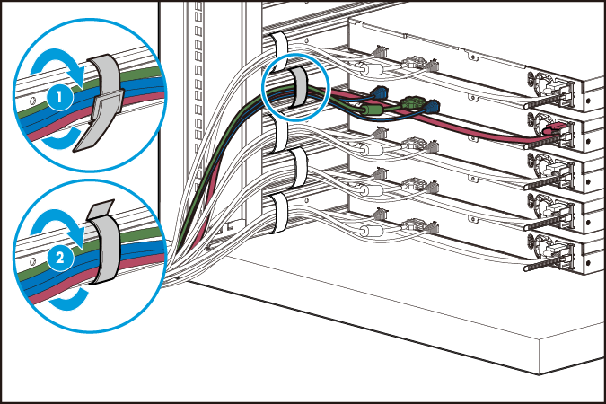
Cabling guidelines
|
|
WARNING! To avoid electric shock, fire, or damage to the equipment, do not connect communication equipment to RJ-45 Ethernet ports on the server. |
· For heat dissipation, make sure no cables block the inlet or outlet air vents of the server.
· To easily identify ports and connect/disconnect cables, make sure the cables do not cross.
· Label the cables for easy identification of the cables.
· Wrap unused cables onto an appropriate position on the rack.
· To avoid damage to cables when extending the server out of the rack, do not route the cables too tight if you use cable management brackets.
Removing the server from a rack
1. Power off the server. For more information, see "Powering off the server."
2. Disconnect all peripheral cables from the server.
3. Extend the server from the rack.
a. Open the latches of the multifunctional rack mount ears, as shown by callout 1 in Figure 63.
b. Loosen the captive screws inside the multifunctional rack mount ears, as shown by callout 2 in Figure 63.
c. Slide the server out of the rack, as shown by callout 3 in Figure 63.
Figure 63 Extending the server from the rack
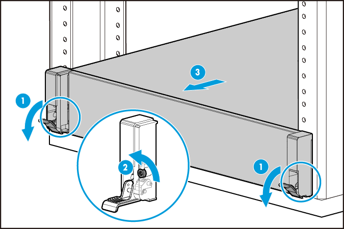
4. Place the server on a clean, stable surface.
Powering on and powering off the server
Important information
If the server is connected to external storage devices, make sure the server is the first device to power off and then the last device to power on. This restriction prevents the server from mistakenly identifying the external storage devices as faulty devices.
Powering on the server
Prerequisites
Before you power on the server, you must complete the following tasks:
· Install the server and internal components correctly.
· Connect the server to a power source.
· As a best practice for the internal components to operate correctly, do not perform the power on action immediately after powering off the server. Wait for over 30 seconds for HDD drives to stop rotation and electronic components to be powered off completely.
Procedure
Powering on the server by pressing the power on/standby button
Press the power on/standby button to power on the server.
The server exits standby mode and supplies power to the system. The system power LED changes from steady amber to flashing green and then to steady green. For information about the position of the system power LED, see Figure 7.
Powering on the server from the HDM Web interface
1. Log in to HDM.
For information about how to log in to HDM, see the HDM2 user guide for the server.
2. Power on the server.
a. Select System > Power Management.
b. Click Power on.
Powering on the server from the remote console interface
1. Log in to HDM.
For information about how to log in to HDM, see the HDM2 user guide for the server.
2. Log in to a remote console and then power on the server.
For information, see HDM2 online help.
Configuring automatic power-on
You can configure automatic power-on from HDM or the BIOS.
To configure automatic power-on from HDM:
1. Log in to HDM.
For information about how to log in to HDM, see the HDM2 user guide for the server.
2. Configure automatic power-on for the server.
a. Select System > Power Management.
b. In the System power restore area, select Always power on, and then click OK.
To configure automatic power-on from the BIOS:
1. Log in to the BIOS.
For information about how to log in to the BIOS, see the BIOS user guide for the server.
2. Configure automatic power-on for the server.
a. Select Server > AC Restore Settings, and then press Enter.
b. Select Always Power On, and then press Enter.
c. Press F4 to save the configuration.
Powering off the server
Guidelines
Before powering off the server, you must complete the following tasks:
· Back up all critical data.
· Make sure all services have stopped or have been migrated to other servers.
Procedure
Powering off the server from its operating system
1. Connect a monitor, mouse, and keyboard to the server.
2. Shut down the operating system of the server.
3. Disconnect all power cords from the server.
Powering off the server by pressing the power on/standby button
1. Press the power on/standby button and wait for the system power LED to turn into steady amber.
2. Disconnect all power cords from the server.
Powering off the server forcedly by pressing the power on/standby button
|
|
IMPORTANT: This method forces the server to enter standby mode without properly exiting applications and the operating system. Use this method only when the server system crashes. For example, a process gets stuck. |
1. Press and hold the power on/standby button until the system power LED turns into steady amber.
2. Disconnect all power cords from the server.
Powering off the server from the HDM Web interface
1. Log in to HDM.
For information about how to log in to HDM, see the HDM2 user guide for the server.
2. Power off the server.
a. Select System > Power Management.
b. Click Graceful power-off.
3. Disconnect all power cords from the server.
Powering off the server from the remote console interface
1. Log in to HDM.
For information about how to log in to HDM, see the HDM2 user guide for the server.
2. Log in to a remote console and then power off the server.
For information about how to log in to a remote console, see HDM online help.
3. Disconnect all power cords from the server.
Configuring the server
The following information describes the procedures to configure the server after the server installation is complete.
Configuration flowchart
Figure 64 Configuration flowchart
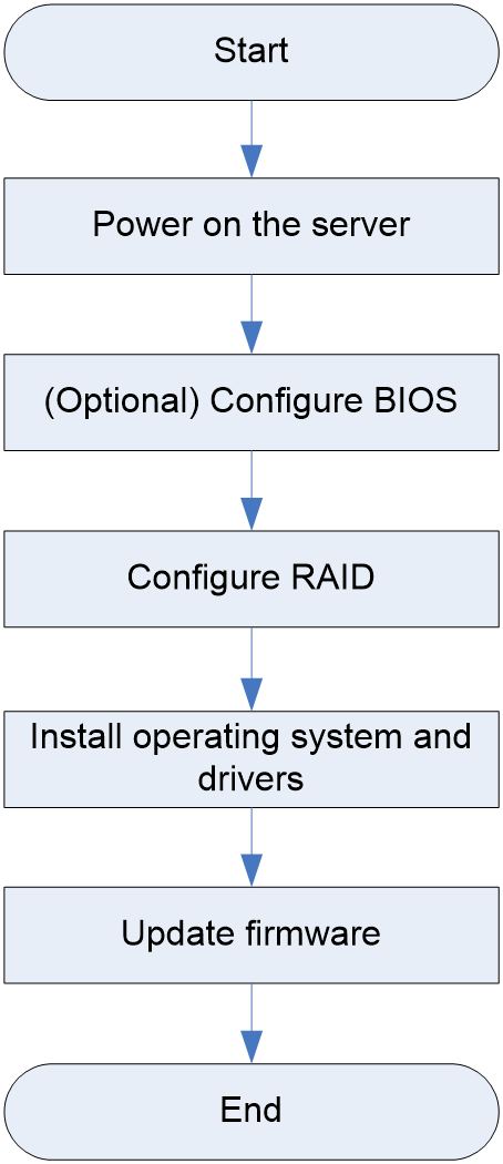
Powering on the server
1. Power on the server. For information about the procedures, see "Powering on the server."
2. Verify that the health LED on the front panel is steady green, which indicates that the system is operating correctly. For more information about the health LED status, see "LEDs and buttons."
Configuring basic BIOS settings
You can set the server boot order and the BIOS passwords from the BIOS setup utility of the server.
|
|
NOTE: The BIOS setup utility screens are subject to change without notice. |
Setting the server boot order
The server has a default boot order. You can change the server boot order from the BIOS. For the default boot order and the procedure of changing the server boot order, see the BIOS user guide for the server.
Setting the BIOS passwords
BIOS passwords include a boot password as well as an administrator password and a user password for the BIOS setup utility. By default, no passwords are set.
To prevent unauthorized access and changes to the BIOS settings, set both the administrator and user passwords for accessing the BIOS setup utility. Make sure the two passwords are different.
After setting the administrator password and user password for the BIOS setup utility, you must enter the administrator password or user password each time you access the system.
· To obtain administrator privileges, enter the administrator password.
· To obtain the user privileges, enter the user password.
For the difference between the administrator and user privileges and guidelines for setting the BIOS passwords, see the BIOS user guide for the server.
Configuring RAID
The embedded SATA storage controller or NVMe storage controller on the server do not support RAID configuration.
Configure physical and logical drives (RAID arrays) for the server.
The supported RAID levels and RAID configuration methods vary by storage controller model. For more information, see the storage controller user guide for the server.
Installing the operating system and hardware drivers
Installing the operating system
Install a compatible operating system on the server by following the procedures described in the operating system installation guide for the server.
For the server compatibility with the operating systems, visit the component compatibility lookup tool at http://www.h3c.com/en/home/qr/default.htm?id=66.
Installing hardware drivers
|
|
IMPORTANT: To avoid hardware unavailability caused by an update failure, always back up the drivers before you update them. |
For newly installed hardware to operate correctly, the operating system must have the required hardware drivers.
To install a hardware driver, see the operating system installation guide for the server.
Updating firmware
|
|
IMPORTANT: Verify the hardware and software compatibility before firmware upgrade. For information about the hardware and software compatibility, see the software release notes. |
You can update the following firmware from UniSystem or HDM:
· HDM.
· BIOS.
· CPLD.
· BPCPLD.
· PSU.
For information about the update procedures, see the firmware update guide for the server.
Replacing hardware options
If you are replacing multiple hardware options, read their replacement procedures and identify similar steps to streamline the entire replacement procedure.
When you remove the access panel for the first time, remove the screws at the two sides of the chassis rear.
Replacing a processor
Application scenarios
Perform this task in the following scenarios:
· The processor fails.
· Replace the processor with one of another model.
· The processor hinders maintenance of other components.
Prerequisites
Take the following ESD prevention measures:
· Wear antistatic clothing.
· Wear an ESD wrist strap and make sure it makes good skin contact and is reliably grounded.
· Do not wear any conductive objects, such as jewelry or watches.
When you replace a component, examine the slot and connector for damages. Make sure the pins are not damaged (bent for example) and do not contain any foreign objects.
For information about installation guidelines, see "Processor."
Procedures
Restrictions and guidelines
To avoid damage to a processor or the system board, only H3C authorized or professional server engineers can replace a processor.
The pins in the processor sockets are very fragile and prone to damage. Install a protective cover if a processor socket is empty.
To prevent static electricity from damaging the electronic components, wear an ESD wrist strap before operation and ground the other end of the ESD wrist strap.
Removing a processor
1. Power off the server. For more information, see "Powering off the server."
2. Remove the server from the rack. For more information, see "Removing the server from a rack."
3. Remove the access panel:
a. Press the button on the locking lever and then lift the locking lever.
The access panel automatically slides to the server rear.
b. Lift the access panel to remove it from the server.
4. Remove the chassis air baffle. Open the blue clip on the air baffle and lift the air baffle out of the chassis.
5. Remove the processor heatsink:
a. Loosen the captive screws strictly in the sequence of 6 to 1 that are labeled on the processor. An incorrect sequence might cause the captive screws to fall off.
b. Lift the heatsink slowly to remove it.
6. Use isopropanol wiping cloth to clear the residual thermal grease from the processor top and heatsink. Make sure the processor and the heatsink are clean.
7. Open the processor cover. Use a T20 Torx screwdriver to loosen the screw on the processor cover. Then, the processor cover automatically pops out.
8. Open the processor frame. Use your index fingers to hold the metal handles to pull up the processor frame until you cannot pull it further.
9. Remove the processor. Pinch the protruding part of the processor carrier to pull it out.
|
|
CAUTION: To avoid component damage, do not drop the processor carrier with the processor or touch the surface of the processor. |
Installing a processor
1. Install the processor carrier with the processor. Pinching the protruding part of the processor carrier, insert it into the processor frame to secure it into place.
|
|
CAUTION: To avoid component damage, do not drop the processor carrier with the processor or touch the surface of the processor. |
2. Close the processor frame. Close the processor frame slowly, and then hold both sides of the frame with your hands until it locks in place.
3. Secure the processor cover. Close the processor cover slowly and use a T20 Torx screwdriver to fasten the screw.
4. Smear thermal grease onto the processor:
a. Clean the heatsink. Make sure no thermal grease remains on the heatsink top.
b. Use the thermal grease injector to inject 0.6 ml of thermal grease to the five dots on the bottom of the heatsink, 0.12 ml for each dot.
5. Install the heatsink.
a. Place the heatsink down onto the processor socket.
b. (Optional.) If the heatsink is a Y-shape heatsink, align the pillars at the horns of the heatsink with the white dots on the system board to identify the installation location.
c. Use a T20 Torx screwdriver to fasten the captive screws on the heatsink strictly in the sequence of 1 to 6 that are labeled on the heatsink. An incorrect sequence might cause the captive screws to fall off.
|
|
CAUTION: · To avoid poor contact between the processor and the system board or damage to the pins in the processor socket, tighten the screws to a torque of 1.6 N·m (16.1 kgf.cm). · Paste the bar code label supplied with the processor over the original label on the heatsink to ensure that you can obtain H3C's processor servicing. |
6. Install the chassis air baffle.
7. Install the access panel:
a. Place the access panel onto the server.
b. Slide the access panel to the server front and close the locking lever. The access panel snaps into place.
8. Rack-mount the server. For more information, see "Rack-mounting the server."
9. Connect the power cord. For more information, see "Connecting the power cord."
10. Power on the server. For more information, see "Powering on the server."
Replacing a DIMM
Application scenarios
Perform this task in the following scenarios:
· The DIMM fails.
· Replace the DIMM with one of another model.
· The DIMM hinders maintenance of other components.
Prerequisites
Take the following ESD prevention measures:
· Wear antistatic clothing.
· Wear an ESD wrist strap and make sure it makes good skin contact and is reliably grounded.
· Do not wear any conductive objects, such as jewelry or watches.
When you replace a component, examine the slot and connector for damages. Make sure the pins are not damaged (bent for example) and do not contain any foreign objects.
For information about installation guidelines, see "DIMMs."
Procedures
Removing a DIMM
1. Power off the server. For more information, see "Powering off the server."
2. Remove the server from the rack. For more information, see "Removing the server from a rack."
3. Remove the access panel:
a. Press the button on the locking lever and then lift the locking lever.
The access panel automatically slides to the server rear.
b. Lift the access panel to remove it from the server.
4. Remove the chassis air baffle. Open the blue clip on the air baffle and lift the air baffle out of the chassis.
5. Remove a DIMM. Open the DIMM slot latches and pull the DIMM out of the slot to remove the DIMM.
|
|
CAUTION: To avoid damage to DIMMs or the system board, make sure the server has been powered off and disconnected from the power cord for at least 20 seconds. |
Installing a DIMM
1. Install the DIMM. Align the notch on the DIMM with the connector key in the DIMM slot and press the DIMM into the socket until the latches lock the DIMM in place.
2. Install the chassis air baffle.
3. Install the access panel:
a. Place the access panel onto the server.
b. Slide the access panel to the server front and close the locking lever. The access panel snaps into place.
4. Rack-mount the server. For more information, see "Rack-mounting the server."
5. Connect the power cord. For more information, see "Connecting the power cord."
6. Power on the server. For more information, see "Powering on the server."
7. (Optional.) To modify the memory mode, enter the BIOS and configure the memory mode as described in the BIOS user manual for the server.
Verifying the replacement
Use one of the following methods to verify that the DIMM is installed correctly:
· Using the operating system:
¡ In Windows, select Run in the Start menu, enter msinfo32, and verify the memory capacity of the DIMM.
¡ In Linux, execute the cat /proc/meminfo command to verify the memory capacity.
· Using HDM:
Log in to HDM and verify the memory capacity of the DIMM. For more information, see the HDM2 online help.
· Using BIOS:
Access the BIOS, select Advanced > Socket Configuration > Memory Configuration > Memory Topology, and press Enter. Then, verify the memory capacity of the DIMM.
If the memory capacity displayed is inconsistent with the actual capacity, remove and then reinstall the DIMM, or replace the DIMM with a new DIMM.
If the DIMM is in Mirror mode, it is normal that the displayed capacity is smaller than the actual capacity.
Replacing the system board
Application scenarios
Perform this task when the system board is faulty.
Prerequisites
Take the following ESD prevention measures:
· Wear antistatic clothing.
· Wear an ESD wrist strap and make sure it makes good skin contact and is reliably grounded.
· Do not wear any conductive objects, such as jewelry or watches.
When you replace a component, examine the slot and connector for damages. Make sure the pins are not damaged (bent for example) and do not contain any foreign objects.
Procedures
Removing the system board
|
|
CAUTION: To prevent electrostatic discharge, place the removed parts on an antistatic surface or in antistatic bags |
1. Power off the server. For more information, see "Powering off the server."
2. Remove the server from the rack. For more information, see "Removing the server from a rack."
3. Remove the access panel:
a. Press the button on the locking lever and then lift the locking lever.
The access panel automatically slides to the server rear.
b. Lift the access panel to remove it from the server.
4. Remove riser cards.
5. Remove the serial & DSD module.
6. Remove the power supplies.
7. Remove the chassis air baffle. Open the blue clip on the air baffle, and lift the air baffle out of the chassis.
8. Remove the fan modules.
9. Remove the fan cage. Pull up the ejector levers at both sides of the fan cage and lift the fan cage to remove it from the chassis.
10. Remove all the DIMMs installed on the system board.
11. Remove the heatsinks.
12. Remove processors.
13. Install protective covers over the empty processor sockets.
14. Disconnect cables from the system board.
15. Remove the system board:
a. Loosen the captive screws on the system board.
b. Hold the system board handle and slide the system board toward the server front to disengage the system board from the server management module. Then, lift the system board out of the chassis.
Installing the system board
1. Install the system board:
a. Slowly place the system board in the chassis. Then, hold the system board handle and slide the system board toward the server rear until the server management module connectors are successfully attached to the system board.
|
|
NOTE: The system board is securely seated if you cannot use the system board handle to lift the system board. |
b. Fasten the captive screws on the system board.
2. Remove the installed protective covers over the processor sockets.
3. Install processors.
4. Connect cables to the system board.
5. Install heatsinks.
6. Install DIMMs.
7. Install the fan cage and fan modules.
8. Install the chassis air baffle.
9. Install the removed power supplies.
10. Install the serial & DSD module.
11. Install riser cards and connect cables to riser cards.
12. Install the access panel.
13. Rack-mount the server. For more information, see "Rack-mounting the server."
14. Connect the power cord. For more information, see "Connecting the power cord."
15. Power on the server. For more information, see "Powering on the server."
Replacing the server management module
Application scenarios
Perform this task when the server management module is faulty.
Prerequisites
Take the following ESD prevention measures:
· Wear antistatic clothing.
· Wear an ESD wrist strap and make sure it makes good skin contact and is reliably grounded.
· Do not wear any conductive objects, such as jewelry or watches.
When you replace a component, examine the slot and connector for damages. Make sure the pins are not damaged (bent for example) and do not contain any foreign objects.
For information about installation guidelines, see "Server management module."
Procedures
Removing the server management module
1. Power off the server. For more information, see "Powering off the server."
2. Remove the server from the rack. For more information, see "Removing the server from a rack."
3. Remove the access panel:
a. Press the button on the locking lever and then lift the locking lever.
The access panel automatically slides to the server rear.
b. Lift the access panel to remove it from the server.
4. Remove riser cards.
5. Remove the serial & DSD module.
6. Remove all the power supplies.
7. Remove the chassis air baffle. Open the blue clip on the air baffle, and lift the air baffle out of the chassis.
8. Remove all fan modules.
9. Remove the fan cage. Pull up the ejector levers at both sides of the fan cage and lift the fan cage to remove it from the chassis.
10. Remove DIMMs from the system board.
11. Remove heatsinks.
12. Remove the processors.
13. Install protective covers over the empty processor sockets.
14. Disconnect cables from the system board.
15. Remove the system board:
a. Loosen the two captive screws on the system board.
b. Hold the system board handle and slide the system board toward the server front to disengage the system board and the server management module. Lift the system board out of the chassis.
16. Remove the server management module. Slide the management module toward the server front to disengage the connectors on the module and the rear panel. Lift the management module out of the chassis.
Installing the server management module
1. Install the server management module. Slowly place the management module into the chassis. Then, slide the management module toward the server rear until the connectors on the module are securely seated.
2. Install the system board:
a. Slowly place the system board into the chassis. Then, hold the system board handle and slide the system board toward the server rear until the system board connector is successfully inserted into the server management module.
|
|
NOTE: The system board is securely seated if you cannot use the system board handle to lift the system board. |
b. Fasten the two captive screws on the system board.
3. Remove the installed protective covers over the processor sockets.
4. Open the frame and install processors.
5. Connect cables to the system board.
6. Install heatsinks.
7. Install DIMMs.
8. Install the fan cage and fan modules.
9. Install the chassis air baffle.
10. Install all the power supplies.
11. Install the serial & DSD module.
12. Install riser cards and connect cables to the riser cards.
13. Install the access panel.
14. Rack-mount the server. For more information, see "Rack-mounting the server."
15. Connect the power cord.
16. Power on the server. For more information, see "Powering on the server."
Replacing a SAS/SATA drive
Application scenarios
Perform this task in the following scenarios:
· The drive is faulty.
· The drive space is used up.
· Replace the drive with one of another model.
Prerequisites
Take the following ESD prevention measures:
· Wear antistatic clothing.
· Wear an ESD wrist strap and make sure it makes good skin contact and is reliably grounded.
· Do not wear any conductive objects, such as jewelry or watches.
When you replace a component, examine the slot and connector for damages. Make sure the pins are not damaged (bent for example) and do not contain any foreign objects.
Identify the position of the drive to be replaced.
Identify the RAID array information of the drive to be replaced. To replace a drive in a non-redundancy RAID array, back up data in the RAID array if the old drive is full or the new drive is of a different model.
For information about installation guidelines, see "SAS/SATA drives."
Procedures
SAS/SATA drives managed by a storage controller support hot swapping only after the device enters the BIOS or operating system.
Removing a SAS/SATA drive
1. Remove the security bezel, if any.
2. Observe the drive LEDs to verify that the drive is not selected by the storage controller and is not performing a RAID migration or rebuilding. For more information about drive LEDs, see "Drive LEDs."
3. Remove the drive:
¡ To remove an SSD, press the button on the drive panel to release the locking lever, and then hold the locking lever and pull the drive out of the slot.
¡ To remove an HDD, press the button on the drive panel to release the locking lever. Pull the drive 3 cm (1.18 in) out of the slot. Wait for a minimum of 30 seconds for the drive to stop rotating, and then pull the drive out of the slot.
4. Remove the drive carrier. Remove the screws that secure the drive and then remove the drive from the carrier.
Installing a SAS/SATA drive
|
|
IMPORTANT: As a best practice, install drives that do not contain RAID information. |
1. Attach the drive to the drive carrier. Place the drive in the carrier and then use four screws to secure the drive into place.
2. Insert the drive into the slot and push it gently until you cannot push it further, and then close the locking lever.
3. Install the security bezel, if any. Press the latch at the other end, close the security bezel, and then release the latch to secure the security bezel into place. Insert the key provided with the bezel into the lock on the bezel and lock the security bezel.
Verifying the replacement
Use one of the following methods to verify that the drive has been replaced correctly:
· Verify the drive properties (including capacity) by using one of the following methods:
¡ Log in to HDM. For more information, see HDM2 online help.
¡ Access the BIOS. For more information, see the storage controller user guide for the server.
¡ Access the CLI or GUI of the server.
· Observe the drive LEDs to verify that the drive is operating correctly. For more information about drive LEDs, see "Drive LEDs."
Adding an NVMe drive
Prerequisites
Take the following ESD prevention measures:
· Wear antistatic clothing.
· Wear an ESD wrist strap and make sure it makes good skin contact and is reliably grounded.
· Do not wear any conductive objects, such as jewelry or watches.
When you replace a component, examine the slot and connector for damages. Make sure the pins are not damaged (bent for example) and do not contain any foreign objects.
Identify the position of the drive to be replaced.
Identify the RAID array information for the drive to be replaced. To replace a drive in a non-redundancy RAID array, back up data in the RAID array if the old drive is full or the new drive is of a different model.
For more information about the installation guidelines, see "NVMe drives."
Installing an NVMe drive
|
|
NOTE: Only some operating systems support the hot insertion of NVMe drives. For more information, use the component compatibility lookup tool at http://www.h3c.com/en/home/qr/default.htm?id=66. |
1. Remove the intelligent security bezel, if any.
2. Install the drive into the drive carrier. Secure the four screws into the screw holes, and then fasten the screws in sequence.
3. Install an NVMe drive. Push the drive into the drive slot and close the locking lever on the drive panel.
4. Install the security bezel, if any. Press the latch at the other end, close the security bezel, and then release the latch to secure the security bezel into place. Insert the key provided with the bezel into the lock on the bezel and lock the security bezel.
Verifying the replacement
Use the following methods to verify that the drive is installed correctly:
· Verify the drive properties (including capacity) by using one of the following methods:
¡ Access HDM. For more information, see HDM2 online help.
¡ Access the BIOS. For more information, see the BIOS user guide for the server.
¡ Access the CLI or GUI of the server.
· Observe the drive LEDs to verify that the drive is operating correctly. For more information, see "Drive LEDs."
Replacing an NVMe drive
Application scenarios
Perform this task in the following scenarios:
· The drive is faulty.
· The drive space is used up.
· Replace the drive with one of another model.
Prerequisites
Take the following ESD prevention measures:
· Wear antistatic clothing.
· Wear an ESD wrist strap and make sure it makes good skin contact and is reliably grounded.
· Do not wear any conductive objects, such as jewelry or watches.
When you replace a component, examine the slot and connector for damages. Make sure the pins are not damaged (bent for example) and do not contain any foreign objects.
Identify the position of the drive to be replaced.
Identify the RAID array information for the drive to be replaced. To replace a drive in a non-redundancy RAID array, back up data in the RAID array if the old drive is full or the new drive is of a different model.
Procedures
|
|
NOTE: · Support for hot swapping of NVMe drives depends on the operating system. For more information, use the component compatibility lookup tool at http://www.h3c.com/en/home/qr/default.htm?id=66. · To replace an NVMe drive in an operating system that does not support hot swapping, first power off the server. For more information, see "Powering off the server." |
Removing an NVMe drive
1. Remove the security bezel, if any.
2. Remove the NVMe drive. Press the button on the drive panel to release the locking lever, and then hold the locking lever and pull the drive out of the slot.
3. Remove the drive carrier. Remove the screws that secure the drive and then remove the drive from the carrier.
Installing an NVMe drive
1. Install an NVMe drive. Attach the drive to the drive carrier. Place the drive in the carrier and then use four screws to secure the drive into place.
2. Insert the drive into the slot and push it gently until you cannot push it further, and then close the locking lever.
3. Install the removed security bezel, if any. Press the latch at the other end, close the security bezel, and then release the latch to secure the security bezel into place. Insert the key provided with the bezel into the lock on the bezel and lock the security bezel.
Verifying the replacement
Use the following methods to verify that the drive is installed correctly:
· Verify the drive properties (including capacity) by using one of the following methods:
¡ Access HDM. For more information, see HDM2 online help.
¡ Access the BIOS. For more information, see the BIOS user guide for the server.
¡ Access the CLI or GUI of the server.
· Observe the drive LEDs to verify that the drive is operating correctly. For more information, see "Drive LEDs."
Replacing a drive backplane
Application scenarios
Perform this task when the drive backplane is faulty.
Prerequisites
Take the following ESD prevention measures:
· Wear antistatic clothing.
· Wear an ESD wrist strap and make sure it makes good skin contact and is reliably grounded.
· Do not wear any conductive objects, such as jewelry or watches.
When you replace a component, examine the slot and connector for damages. Make sure the pins are not damaged (bent for example) and do not contain any foreign objects.
Procedure
Removing a drive backplane
1. Power off the server. For more information, see "Powering off the server."
2. Remove the server from the rack. For more information, see "Removing the server from a rack."
3. Remove the drives attached to the backplane.
4. Remove the access panel:
a. Press the button on the locking lever and then lift the locking lever.
The access panel automatically slides to the server rear.
b. Lift the access panel to remove it from the server.
5. Remove the fan modules.
6. Remove the fan cage. Pressing the locking tabs at both ends of the fan cage, lift the fan cage to remove it out of the chassis.
7. Disconnect cables from the backplane.
8. Remove the drive backplane. Loosen the captive screws that secure the backplane, and then lift the backplane out of the chassis.
Installing a drive backplane
1. Install a drive backplane. Place the backplane in the slot and then fasten the captive screws.
2. Connect cables to the drive backplane.
3. Install the fan cage.
4. Install the fan modules.
5. Install the access panel:
a. Place the access panel onto the server.
b. Slide the access panel to the server front and close the locking lever. The access panel snaps into place.
6. Install the removed drives.
7. Rack-mount the server. For more information, see "Rack-mounting the server."
8. Connect the power cord. For more information, see "Connecting the power cord."
9. Power on the server. For more information, see "Powering on the server."
Installing a rear drive cage
Prerequisites
Take the following ESD prevention measures:
· Wear antistatic clothing.
· Wear an ESD wrist strap and make sure it makes good skin contact and is reliably grounded.
· Do not wear any conductive objects, such as jewelry or watches.
· When you replace a component, examine the slot and connector for damages. Make sure the pins are not damaged (bent for example) and do not contain any foreign objects.
Procedure
1. Power off the server. For more information, see "Powering off the server."
2. Remove the server from the rack. For more information, see "Removing the server from a rack."
3. Remove the access panel:
a. Press the button on the locking lever and then lift the locking lever.
The access panel automatically slides to the server rear.
b. Lift the access panel to remove it from the server.
4. Remove the PCIe riser card blank. Lift the blank to remove it from the chassis.
5. For a 2SFF UniBay drive cage, install a bracket:
a. Align the guide pin on the bracket with the notch in the chassis.
b. Place the bracket in the chassis.
c. Use screws to secure the bracket.
6. Install the rear drive cage:
a. Place the drive cage in the chassis.
b. Use screws to secure the drive cage.
7. Connect the cables. See "Connecting drive cables."
8. Install the blank. Aligning the guide pins on the blank with the notches in the chassis, insert the blank into the slot.
9. Install the access panel:
a. Place the access panel onto the server.
b. Slide the access panel to the server front and close the locking lever. The access panel snaps into place.
10. Rack-mount the server. For more information, see "Rack-mounting the server."
11. Connect the power cord.
12. Power on the server. For more information, see "Powering on the server."
Replacing riser cards and PCIe modules
Application scenarios
Perform this task in the following scenarios:
· This riser card is faulty.
· The PCIe module is faulty.
· Replace the riser card or PCIe module with one of another model.
Prerequisites
Take the following ESD prevention measures:
· Wear antistatic clothing.
· Wear an ESD wrist strap and make sure it makes good skin contact and is reliably grounded.
· Do not wear any conductive objects, such as jewelry or watches.
When you replace a component, examine the slot and connector for damages. Make sure the pins are not damaged (bent for example) and do not contain any foreign objects.
For information about installation guidelines, see "Riser cards and PCIe modules."
Procedures
Removing a riser card and a PCIe module
1. Power off the server. For more information, see "Powering off the server."
2. Remove the server from the rack. For more information, see "Removing the server from a rack."
3. Remove the access panel:
a. Press the button on the locking lever and then lift the locking lever.
The access panel automatically slides to the server rear.
b. Lift the access panel to remove it from the server.
4. Disconnect all cables that hinder the replacement, if any.
5. Remove the riser card installed with a PCIe module. Pressing the unlocking button, lift the riser card out of the chassis.
6. Remove the PCIe module from the riser card:
a. Remove the screws on the riser card.
b. Pull the PCIe module out of the slot.
Installing a riser card and a PCIe module
1. Install the PCIe module on the riser card:
a. Remove the PCIe module blank. Remove the screws on the blank, and then pull out the blank.
b. Install the PCIe module to the riser card. Insert the PCIe module into the PCIe slot along the guide rails, and then use screws to secure the PCIe module.
2. Install the riser card on the server:
a. Lift the riser card blank to remove it from the chassis.
b. Install the riser card on the PCIe riser connector. Pressing the unlocking button, insert the riser card into the PCIe riser slot along the rails. Make sure the unlocking button is in locked position.
3. Connect cables to the riser card or PCIe modules, if any.
4. Install the access panel:
a. Place the access panel onto the server.
b. Slide the access panel to the server front and close the locking lever. The access panel snaps into place.
5. Rack-mount the server. For more information, see "Rack-mounting the server."
6. Connect the power cord.
7. Power on the server. For more information, see "Powering on the server."
Installing PCIe modules and a riser card on PCIe riser bay 3
Prerequisites
Take the following ESD prevention measures:
· Wear antistatic clothing.
· Wear an ESD wrist strap and make sure it makes good skin contact and is reliably grounded.
· Do not wear any conductive objects, such as jewelry or watches.
When you replace a component, examine the slot and connector for damages. Make sure the pins are not damaged (bent for example) and do not contain any foreign objects.
For information about installation guidelines, see "Riser cards and PCIe modules."
Procedure
1. Identify the position of the PCIe riser connector. For more information, see "System board components."
2. Power off the server. For more information, see "Powering off the server."
3. Remove the server from the rack. For more information, see "Removing the server from a rack."
4. Remove the access panel:
a. Press the button on the locking lever and then lift the locking lever.
The access panel automatically slides to the server rear.
b. Lift the access panel to remove it from the server.
5. Lift the PCIe riser card blank to remove it.
6. Assemble the riser 3 assembly module in advance as required.
7. Install a PCIe module to the riser 3 assembly module:
a. Remove the PCIe module blank. Loosen the screws on the PCIe module blank, and then remove the PCIe module blank.
b. Install the PCIe module into the riser card. Insert the PCIe module into the PCIe slot along the guide rails, and fasten the screws to secure the PCIe module.
8. Install the support bracket:
a. Align the holes on the support bracket with the guide holes on the chassis.
b. Place the support bracket onto the chassis.
c. Fasten the screws to secure the support bracket.
9. Install the riser 3 assembly module with the PCIe module to PCIe riser bay 3. To secure the riser 3 assembly module into place, make sure the protruding metal piece on the riser 3 assembly module is aligned with the left hole on the power supply air baffle.
10. Connect cables on the riser 3 assembly module.
11. Install the access panel:
a. Place the access panel onto the server.
b. Slide the access panel to the server front and close the locking lever. The access panel snaps into place.
12. Rack-mount the server. For more information, see "Rack-mounting the server."
13. Connect the power cord.
14. Power on the server. For more information, see "Powering on the server."
Installing PCIe modules and a riser card on PCIe riser bay 4
Prerequisites
Take the following ESD prevention measures:
· Wear antistatic clothing.
· Wear an ESD wrist strap and make sure it makes good skin contact and is reliably grounded.
· Do not wear any conductive objects, such as jewelry or watches.
When you replace a component, examine the slot and connector for damages. Make sure the pins are not damaged (bent for example) and do not contain any foreign objects.
For information about installation guidelines, see "Riser cards and PCIe modules."
Procedure
1. Power off the server. For more information, see "Powering off the server."
2. Remove the server from the rack. For more information, see "Removing the server from a rack."
3. Remove the access panel:
a. Press the button on the locking lever and then lift the locking lever.
The access panel automatically slides to the server rear.
b. Lift the access panel to remove it from the server.
4. Lift the PCIe riser card blank to remove it.
5. Assemble the riser 4 assembly module in advance as required.
6. Install a PCIe module to the riser 4 assembly module:
a. Remove the PCIe module blank. Loosen the screws on the PCIe module blank, and then remove the PCIe module blank.
b. Install the PCIe module into the riser card. Insert the PCIe module into the PCIe slot along the guide rails, and fasten the screws to secure the PCIe module.
7. Install the support brackets. Align the holes of a support bracket with the guide holes on the chassis, place down the support bracket, and then fasten the screws to secure the support bracket.
8. Install the riser 4 assembly module with the PCIe module to PCIe riser bay 4. To secure the riser 4 assembly module into place, make sure the protruding metal piece on the riser 3 assembly module is aligned with the mid hole on the power supply air baffle.
9. Connect cables on the riser 4 assembly module.
10. Install the access panel:
a. Place the access panel onto the server.
b. Slide the access panel to the server front and close the locking lever. The access panel snaps into place.
11. Rack-mount the server. For more information, see "Rack-mounting the server."
12. Connect the power cord.
13. Power on the server. For more information, see "Powering on the server."
Replacing a storage controller and a power fail safeguard module
Application scenarios
Perform this task in the following scenarios:
· The storage controller is faulty.
· Replace the storage controller with one of another model.
· The storage controller hinders maintenance of other components.
· The power fail safeguard module is faulty.
· The power fail safeguard module hinders maintenance of other components.
Prerequisites
Take the following ESD prevention measures:
· Wear antistatic clothing.
· Wear an ESD wrist strap and make sure it makes good skin contact and is reliably grounded.
· Do not wear any conductive objects, such as jewelry or watches.
When you replace a component, examine the slot and connector for damages. Make sure the pins are not damaged (bent for example) and do not contain any foreign objects.
To replace the storage controller with a controller of the same model, clearly identify the storage controller and its BIOS information.
· The storage controller's position in the server and cable connection method.
· Model, operation mode, and firmware version of the storage controller.
· BIOS boot mode.
· First boot option setting for the storage controller in Legacy boot mode.
To replace the storage controller with a controller of a different model, back up data in the drives of the storage controller and clear RAID configuration.
For information about installation guidelines, see "Storage controllers and power fail safeguard modules."
Procedures
Removing a standard storage controller and a power fail safeguard module
1. Power off the server. For more information, see "Powering off the server."
2. Remove the server from the rack. For more information, see "Removing the server from a rack."
3. Remove the access panel:
a. Press the button on the locking lever and then lift the locking lever.
The access panel automatically slides to the server rear.
b. Lift the access panel to remove it from the server.
4. Disconnect all cables from the standard storage controller.
5. Remove the standard storage controller:
a. Remove the riser card where the standard storage controller resides. Lift the riser card to remove the riser card from the chassis.
b. Remove the standard storage controller from the riser card. Open the retaining latch on the riser card, and then pull the storage controller out from the slot.
6. Remove the power fail safeguard module or super capacitor, if any. Open the protective cover over the supercapacitor, and take the supercapacitor out of the holder.
Installing a standard storage controller and a power fail safeguard module
1. (Optional.) Install the supercapacitor. Place the supercapacitor into the holder as instructed on the holder, and close the protective cover.
2. Install the standard storage controller on the riser card. Insert the standard storage controller into the PCIe slot along the guide rails, and then close the retaining latch on the riser card.
3. Install the riser card on the server.
4. Connect the cables for the standard storage controller to the drive backplane. For more information, see "Connecting drive cables."
5. Install the removed power fail safeguard module or supercapacitor. Connect the supercapacitor extension cable to the flash card. For more information, see "Connecting the supercapacitor cable."
6. Install the access panel:
a. Place the access panel onto the server.
b. Slide the access panel to the server front and close the locking lever. The access panel snaps into place.
7. Rack-mount the server. For more information, see "Rack-mounting the server."
8. Connect the power cord.
9. Power on the server. For more information, see "Powering on the server."
Replacing a GPU module
Application scenarios
Perform this task in the following scenarios:
· The GPU module is faulty.
· Replace the GPU module with one of another model.
· The GPU module hinders maintenance of other components.
Prerequisites
Take the following ESD prevention measures:
· Wear antistatic clothing.
· Wear an ESD wrist strap and make sure it makes good skin contact and is reliably grounded.
· Do not wear any conductive objects, such as jewelry or watches.
When you replace a component, examine the slot and connector for damages. Make sure the pins are not damaged (bent for example) and do not contain any foreign objects.
For information about installation guidelines, see "GPU modules."
Procedures
Removing a GPU module
1. Power off the server. For more information, see "Powering off the server."
2. Remove the server from the rack. For more information, see "Removing the server from a rack."
3. Remove the access panel:
a. Press the button on the locking lever and then lift the locking lever.
The access panel automatically slides to the server rear.
b. Lift the access panel to remove it from the server.
4. Disconnect all cables that hinder the replacement, if any.
5. Remove the riser card where the GPU module resides. Pressing the unlocking button on the riser card, lift the riser card out of the chassis.
6. Remove the GPU module from the riser card:
a. Disconnect the cable from the GPU module.
b. Open the retaining latch on the riser card, and pull the GPU module out from the slot.
(Optional) Adjusting the form of the riser card
|
|
IMPORTANT: To replace the GPU module with a new one of different length, adjust the riser card form as needed. |
1. Remove the screws on the riser card.
2. Adjust the riser card length. You can have a short or long riser card as needed.
3. Fasten the screws to secure the riser card to its new form.
4. Replace the air baffle for the new form of the riser card.
Installing a GPU module
1. Install a GPU module on the riser card:
a. Insert the GPU module into the PCIe slot along the guide rails, and then close the retaining latch on the riser card.
b. (Optional.) Connect the GPU module power cord according to the cable label.
2. Reconnect other cables to the riser card.
3. Install the riser card on the server. Pressing the unlocking button, insert the riser card into the PCIe riser slot along the rails. Make sure the unlocking button is in locked position.
4. Install the access panel:
a. Place the access panel onto the server.
b. Slide the access panel to the server front and close the locking lever. The access panel snaps into place.
5. Rack-mount the server. For more information, see "Rack-mounting the server."
6. Connect the power cord.
7. Power on the server. For more information, see "Powering on the server."
Replacing a standard PCIe network adapter
Application scenarios
Perform this task in the following scenarios:
· The standard PCIe network adapter is faulty.
· Replace the standard PCIe network adapter with one of another model.
Prerequisites
Take the following ESD prevention measures:
· Wear antistatic clothing.
· Wear an ESD wrist strap and make sure it makes good skin contact and is reliably grounded.
· Do not wear any conductive objects, such as jewelry or watches.
When you replace a component, examine the slot and connector for damages. Make sure the pins are not damaged (bent for example) and do not contain any foreign objects.
For information about installation guidelines, see "Network adapters."
Procedures
Removing a standard PCIe network adapter
1. Power off the server. For more information, see "Powering off the server."
2. Disconnect cables from the standard PCIe network adapter.
3. Remove the server from the rack. For more information, see "Removing the server from a rack."
4. Remove the access panel:
a. Press the button on the locking lever and then lift the locking lever.
The access panel automatically slides to the server rear.
b. Lift the access panel to remove it from the server.
5. Disconnect all cables that hinder the replacement, if any.
6. Remove the riser card that holds the PCIe network adapter. Lift the riser card to remove it from the chassis.
7. Remove the PCIe network adapter from the riser card. Loosen the captive screws on the riser card and pull the PCIe network adapter out of the slot.
Installing a standard PCIe network adapter
For more information, see "Installing a riser card and a PCIe module."
Adding an OCP network adapter
Prerequisites
Take the following ESD prevention measures:
· Wear antistatic clothing.
· Wear an ESD wrist strap and make sure it makes good skin contact and is reliably grounded.
· Do not wear any conductive objects, such as jewelry or watches.
When you replace a component, examine the slot and connector for damages. Make sure the pins are not damaged (bent for example) and do not contain any foreign objects.
Procedure
1. Power off the server. For more information, see "Powering off the server."
2. Remove the server from the rack. For more information, see "Removing the server from a rack."
3. Remove the access panel:
a. Press the button on the locking lever and then lift the locking lever.
b. Lift the access panel to remove it from the server.
4. Remove the rear drive support bracket next to OCP network adapter slot 1 on the system board. Loosen the screws that secure the bracket, and remove the bracket.
5. Secure the connector end of the cable for OCP network adapter slot 1. Place the connector onto OCP network adapter slot 1, and use screws to secure the connector in place.
6. Connect the cable for OCP network adapter slot 1.
7. Install the rear drive support bracket.
8. Remove the blank over OCP network adapter slot 1.
9. Install an OCP network adapter. Take the network adapter out of the antistatic bag, push the network adapter into the slot slowly, and then fasten the captive screw on the network adapter.
10. Install the access panel:
a. Place the access panel onto the server.
b. Slide the access panel to the server front and close the locking lever. The access panel snaps into place.
11. Rack-mount the server. For more information, see "Rack-mounting the server."
12. Connect the power cord.
13. Power on the server. For more information, see "Powering on the server."
Replacing an OCP network adapter
Application scenarios
Perform this task in the following scenarios:
· The OCP network adapter is faulty.
· Replace the OCP network adapter with one of another model.
Prerequisites
Take the following ESD prevention measures:
· Wear antistatic clothing.
· Wear an ESD wrist strap and make sure it makes good skin contact and is reliably grounded.
· Do not wear any conductive objects, such as jewelry or watches.
When you replace a component, examine the slot and connector for damages. Make sure the pins are not damaged (bent for example) and do not contain any foreign objects.
For information about installation guidelines, see "Network adapters."
Procedures
|
|
NOTE: · Some operating systems support managed hot swapping of some OCP network adapters. To replace such an OCP network adapter, you do not need to power off the server. For more information about managed removal, see "Appendix B Managed removal of OCP network adapters." · This section describes the procedure to replace an OCP network adapter that does not support managed hot swapping. |
Removing an OCP network adapter
1. Power off the server. For more information, see "Powering off the server."
2. Disconnect all cables from the OCP network adapter.
3. Remove the OCP network adapter: Loosen the captive screws on the OCP network adapter and pull the OCP network adapter out from the chassis.
Installing an OCP network adapter
1. Install the OCP network adapter: Insert the OCP network adapter into the slot and fasten the captive screws on it.
2. Connect cables to the OCP network adapter.
3. Power on the server. For more information, see "Powering on the server."
4. (Optional.) Configure a network port on the OCP network adapter as an HDM shared network port.
OCP network adapters inserted into OCP adapter slots support NCSI. By default, port 1 on an OCP network adapter acts as the HDM shared network port. You can specify another port on the OCP network adapter as the HDM shared network port from the HDM Web interface. Note that you can specify only one port as the HDM shared network port at the same time.
Replacing a SATA M.2 SSD and the front M.2 SSD expander module
Application scenarios
Perform this task in the following scenarios:
· The SATA M.2 SSD drive is faulty.
· The M.2 SSD expander module is faulty.
· Replace the SATA M.2 SSD drive with one of another model.
Prerequisites
Take the following ESD prevention measures:
· Wear antistatic clothing.
· Wear an ESD wrist strap and make sure it makes good skin contact and is reliably grounded.
· Do not wear any conductive objects, such as jewelry or watches.
When you replace a component, examine the slot and connector for damages. Make sure the pins are not damaged (bent for example) and do not contain any foreign objects.
For information about installation guidelines, see "M.2 SSD drives."
Procedures
Removing a SATA M.2 SSD and the M.2 SSD expander module
1. Power off the server. For more information, see "Powering off the server."
2. Remove the server from the rack. For more information, see "Removing the server from a rack."
3. Remove the access panel:
a. Press the button on the locking lever and then lift the locking lever.
The access panel automatically slides to the server rear.
b. Lift the access panel to remove it from the server.
4. Remove the SATA M.2 SSD expander module that holds the SATA M.2 SSD:
a. Disconnect the cable from the SATA M.2 SSD expander module.
b. Remove the expander module. Remove the screws that secure the expander module and then pull the expander module out.
5. Remove the SATA M.2 SSD. Slide the locking tab, lift the SSD, and then pull the SSD out of the slot.
Installing a SATA M.2 SSD and the M.2 SSD expander module
1. Install the SATA M.2 SSD to the SATA M.2 SSD expander module. Insert the connector of the SSD into the socket, slide the locking tab, press the SSD to secure the SSD into place, and then release the locking tab.
2. Install the expander module.
a. Align the two screw holes in the expander module with the two internal threaded studs on the chassis, put the expander module onto the chassis, and then use screws to secure the expander module.
b. Connect the SATA M.2 SSD cable. For more information, see "Connecting cables for the front M.2 SSD expander module."
3. Install the access panel:
a. Place the access panel onto the server.
b. Slide the access panel to the server front and close the locking lever. The access panel snaps into place.
4. Rack-mount the server. For more information, see "Rack-mounting the server."
5. Connect the power cord.
6. Power on the server. For more information, see "Powering on the server."
Replacing a serial & DSD module
Prerequisites
Take the following ESD prevention measures:
· Wear antistatic clothing.
· Wear an ESD wrist strap and make sure it makes good skin contact and is reliably grounded.
· Do not wear any conductive objects, such as jewelry or watches.
When you replace a component, examine the slot and connector for damages. Make sure the pins are not damaged (bent for example) and do not contain any foreign objects.
For information about installation guidelines, see "Serial & DSD module."
Procedures
Removing a serial & DSD module
1. Power off the server. For more information, see "Powering off the server."
2. Remove the serial & DSD module. Loosen the captive screw on the module and pull the module out of the slot.
Installing a serial & DSD module
1. Install the serial & DSD module. Insert the module into the slot and fasten the captive screw on the module.
2. Power on the server. For more information, see "Powering on the server."
Replacing an SD card
Application scenarios
Perform this task in the following scenarios:
· The SD card is faulty.
· The serial & DSD module is faulty.
· Replace the SD card with one of another model.
Prerequisites
Take the following ESD prevention measures:
· Wear antistatic clothing.
· Wear an ESD wrist strap and make sure it makes good skin contact and is reliably grounded.
· Do not wear any conductive objects, such as jewelry or watches.
When you replace a component, examine the slot and connector for damages. Make sure the pins are not damaged (bent for example) and do not contain any foreign objects.
For information about installation guidelines, see "Serial & DSD module."
Procedures
Removing an SD card and serial & DSD module
1. Power off the server. For more information, see "Powering off the server."
2. Remove the serial & DSD module. Loosen the captive screw on the module and pull the module out of the slot.
3. Remove each of the SD cards installed on the serial & DSD module:
a. Press the SD card to release it.
b. Pull the SD card out of the slot.
Installing an SD card and serial & DSD module
1. Install a new SD card on the serial & DSD module. Insert the SD card into the slot and gently press the SD card to secure it in the slot.
2. Install the serial & DSD module on the server. Insert the module into the slot and fasten the captive screw on the module.
3. Power on the server. For more information, see "Powering on the server."
Replacing a chassis ear
Application scenarios
Perform this task in the following scenarios:
· The chassis ear is faulty.
· Any of the components (for example, I/O components or VGA/USB connectors) attached to the chassis ear fails.
Procedures
The procedure is the same for the left and right chassis ears. This section uses the left chassis ear as an example.
Removing a chassis ear
1. Power off the server. For more information, see "Powering off the server."
2. Remove the server from the rack. For more information, see "Removing the server from a rack."
3. Remove the access panel:
a. Press the button on the locking lever and then lift the locking lever.
The access panel automatically slides to the server rear.
b. Lift the access panel to remove it from the server.
4. Remove the fan cage. Pull up the ejector levers at both sides of the fan cage and lift the fan cage to remove it from the chassis.
5. Remove the chassis air baffle. Lift the air baffle out of the chassis.
6. Remove the front I/O component cable assembly:
a. Disconnect the front I/O component cable assembly from the system board.
b. Remove the cable protection plate. Remove the captive screws that secure the cable protection plate, press the cable protection plate and slide it toward the rear of the chassis until you cannot slide it further, and then pull out the cable protection plate.
c. Remove the front I/O component cable assembly.
7. Remove the chassis ear. Remove the screws that secure the left chassis ear, and then pull the chassis ear until it is removed.
Installing a chassis ear
1. Install a chassis ear. Attach the chassis ear to the corresponding side of the server, and use screws to secure the chassis ear into place.
2. Install the front I/O component cable assembly:
a. Insert the front I/O component cable assembly into the cable cutout.
b. Install the cable protection plate on the chassis. Insert the cable protection plate along the slot and slide it toward the front of the chassis until you cannot slide it further, and then install the captive screws on the cable protection plate.
c. Connect the front I/O component cable assembly to the front I/O connector on the system board.
3. Install the fan cage. Place the fan cage into the chassis and close the ejector levers.
4. Install the chassis air baffle.
5. Install the access panel:
a. Place the access panel onto the server.
b. Slide the access panel to the server front and close the locking lever. The access panel snaps into place.
6. Rack-mount the server. For more information, see "Rack-mounting the server."
7. Connect the power cord. For more information, see "Connecting the power cord."
8. Power on the server. For more information, see "Powering on the server."
Replacing a chassis air baffle
Application scenarios
You might need to replace the chassis air baffle on the server if it is not compatible with the riser cards you are installing.
Procedures
Removing a chassis air baffle
1. Power off the server. For more information, see "Powering off the server."
2. Remove the server from the rack. For more information, see "Removing the server from a rack."
3. Remove the access panel:
a. Press the button on the locking lever and then lift the locking lever.
The access panel automatically slides to the server rear.
b. Lift the access panel to remove it from the server.
4. Remove the chassis air baffle. Press the tabs on the air baffle, and then lift the air baffle out of the chassis.
Installing a chassis air baffle
1. Install the chassis air baffle. Place the chassis air baffle in the chassis.
2. Install the access panel:
a. Place the access panel onto the server.
b. Slide the access panel to the server front and close the locking lever. The access panel snaps into place.
3. Rack-mount the server. For more information, see "Rack-mounting the server."
4. Connect the power cord. For more information, see "Connecting the power cord."
5. Power on the server. For more information, see "Powering on the server."
Adding an LCD smart management module
Prerequisites
Take the following ESD prevention measures:
· Wear antistatic clothing.
· Wear an ESD wrist strap and make sure it makes good skin contact and is reliably grounded.
· Do not wear any conductive objects, such as jewelry or watches.
When you replace a component, examine the slot and connector for damages. Make sure the pins are not damaged (bent for example) and do not contain any foreign objects.
Procedures
1. Power off the server. For more information, see "Powering off the server."
2. Remove the server from the rack. For more information, see "Removing the server from a rack."
3. Remove the access panel:
a. Press the button on the locking lever and then lift the locking lever.
The access panel automatically slides to the server rear.
b. Lift the access panel to remove it from the server.
4. Remove the fan cage. Pull up the ejector levers at both sides of the fan cage and lift the fan cage to remove it from the chassis.
5. Remove the drive or blank from the target slot.
6. Install the LCD smart management module.
a. Connect one end of the LCD module cable to the LCD smart management module.
b. Push the LCD smart management module into the slot until it snaps into place.
c. Connect the other end of the cable to the LCD smart management module connector on the system board.
7. Install the fan cage. Place the fan cage into the chassis and close the ejector levers.
8. Install the access panel.
a. Place the access panel onto the server.
b. Slide the access panel to the server front and close the locking lever. The access panel snaps into place.
9. Rack-mount the server. For more information, see "Rack-mounting the server."
10. Connect the power cord. For more information, see "Connecting the power cord."
11. Power on the server. For more information, see "Powering on the server."
Replacing an LCD smart management module
Applications scenarios
Perform this task in the following scenarios:
· The LCD smart management module is faulty.
· The LCD smart management module hinders the maintenance of other components.
Prerequisites
Take the following ESD prevention measures:
· Wear antistatic clothing.
· Wear an ESD wrist strap and make sure it makes good skin contact and is reliably grounded.
· Do not wear any conductive objects, such as jewelry or watches.
When you replace a component, examine the slot and connector for damages. Make sure the pins are not damaged (bent for example) and do not contain any foreign objects.
Procedures
Removing the LCD smart management module
1. Power off the server. For more information, see "Powering off the server."
2. Disconnect the power cord.
3. Remove the server from the rack. For more information, see "Removing the server from a rack."
4. Remove the access panel:
a. Press the button on the locking lever and then lift the locking lever.
The access panel automatically slides to the server rear.
b. Lift the access panel to remove it from the server.
5. Remove the fan cage. Pull up the ejector levers at both sides of the fan cage and lift the fan cage to remove it from the chassis.
6. Remove the LCD smart management module.
a. Disconnect the LCD module adapter cable from the system board.
b. Use a flat-head screwdriver or tweezers to hold down the release clips of the LCD smart management module, and then pull the LCD smart management module out of the slot.
Installing the LCD smart management module
1. Install the LCD smart management module.
a. Connect one end of the LCD module cable to the LCD smart management module.
b. Push the LCD smart management module into the slot until it snaps into place.
c. Connect the other end of the cable to the LCD smart management module connector on the system board.
2. Install the fan cage. Place the fan cage into the chassis and close the ejector levers.
3. Install the access panel.
a. Place the access panel onto the server.
b. Slide the access panel to the server front and close the locking lever. The access panel snaps into place.
4. Rack-mount the server. For more information, see "Rack-mounting the server."
5. Connect the power cord.
6. Power on the server. For more information, see "Powering on the server."
Replacing a fan module
Applications scenarios
Perform this task in the following scenarios:
· The fan module is faulty.
· Replace the fan module with one of another model.
Procedures
If sufficient space is available for replacement, you can replace a fan module without removing the server from the rack.
Removing a fan module
1. Power off the server. For more information, see "Powering off the server."
2. Remove the server from the rack. For more information, see "Removing the server from a rack."
3. Remove the access panel:
a. Press the button on the locking lever and then lift the locking lever.
The access panel automatically slides to the server rear.
b. Lift the access panel to remove it from the server.
4. Remove a fan module. Lift the fan module handle and hold the handle to pull the fan module out of the slot.
Installing a fan module
1. Install a new fan module. Insert the fan module into the slot and press the fan module until it is secured in position.
2. Install the access panel:
a. Place the access panel onto the server.
b. Slide the access panel to the server front and close the locking lever. The access panel snaps into place.
3. Rack-mount the server if the server has been removed. For more information, see "Rack-mounting the server."
4. Connect the power cord if the power cord has been disconnected. For more information, see "Connecting the power cord."
5. Power on the server if the server has been powered off. For more information, see "Powering on the server."
Installing and setting up a TCM or TPM
Trusted platform module (TPM) is a microchip embedded in the system board. It stores encryption information (such as encryption keys) for authenticating server hardware and software. The TPM operates with drive encryption programs such as Microsoft Windows BitLocker to provide operating system security and data protection. For information about Microsoft Windows BitLocker, visit the Microsoft website at http://www.microsoft.com.
Trusted cryptography module (TCM) is a trusted computing platform-based hardware module with protected storage space, which enables the platform to implement password calculation.
Installation and setup flowchart
Figure 65 TCM/TPM installation and setup flowchart
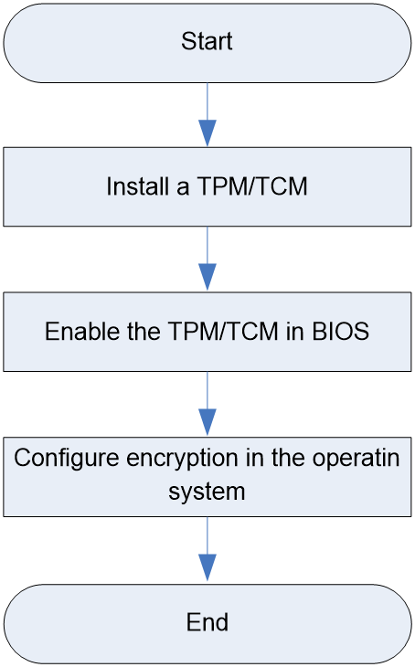
Prerequisites
Take the following ESD prevention measures:
· Wear antistatic clothing.
· Wear an ESD wrist strap and make sure it makes good skin contact and is reliably grounded.
· Do not wear any conductive objects, such as jewelry or watches.
When you replace a component, examine the slot and connector for damages. Make sure the pins are not damaged (bent for example) and do not contain any foreign objects.
Installing a TCM or TPM
Procedure
1. Power off the server. For more information, see "Powering off the server."
2. Remove the server from the rack. For more information, see "Removing the server from a rack."
3. Remove the access panel:
a. Press the button on the locking lever and then lift the locking lever.
The access panel automatically slides to the server rear.
b. Lift the access panel to remove it from the server.
4. Remove all riser cards that hider the installation.
5. Install the TCM or TPM.
The installation procedure is the same for a TPM and a TCM. The following information uses a TPM to show the procedure:
a. Press the TPM into the TPM connector on the system board.
b. Insert the rivet pin.
c. Insert the security rivet into the hole in the rivet pin and press the security rivet until it is firmly seated.
6. Install the removed riser cards, if any.
7. Install the access panel:
a. Place the access panel onto the server.
b. Slide the access panel to the server front and close the locking lever. The access panel snaps into place.
8. Rack-mount the server. For more information, see "Rack-mounting the server."
9. Connect the power cord.
10. Power on the server. For more information, see "Powering on the server."
Guidelines after installation
· Do not remove an installed TCM or TPM. Once installed, the module becomes a permanent part of the system board.
· If you want to replace the failed TCM or TPM, remove the system board, and then contact H3C Support to replace the TCM or TPM and the system board.
· When installing or replacing hardware, H3C technicians cannot configure the TCM or TPM or enter the recovery key. For security reasons, only the user can perform the tasks.
· When replacing the system board, do not remove the TCM or TPM from the system board. H3C will provide a TCM or TPM with a spare system board for the replacement.
· Any attempt to remove an installed TCM or TPM from the system board breaks or disfigures the TCM or TPM security rivet. Upon locating a broken or disfigured rivet on an installed TCP or TPM, administrators should consider the system compromised and take appropriate measures to ensure the integrity of the system data.
· H3C is not liable for blocked data access caused by improper use of the TCM or TPM. For more information, see the encryption technology feature documentation provided by the operating system.
Enabling the TCM or TPM in the BIOS
1. Access the BIOS utility. For information about how to enter the BIOS utility, see the BIOS user guide.
2. Select Advanced > Trusted Computing, and press Enter.
3. Enable TCM or TPM. By default, the TCM and TPM are enabled for a server.
If the server is installed with a TPM, select TPM State > Enabled, and then press Enter.
If the TPM is installed with a TCM, select TCM State > Enabled, and then press Enter.
4. Log in to HDM to verify that the TCM or TPM is operating correctly. For more information, see HDM2 online help.
Configuring encryption in the operating system
For more information about this task, see the encryption technology feature documentation that came with the operating system.
The recovery key/password is generated during BitLocker setup, and can be saved and printed after BitLocker is enabled. When using BitLocker, always retain the recovery key/password. The recovery key/password is required to enter Recovery Mode after BitLocker detects a possible compromise of system integrity or firmware or hardware change.
For security purposes, follow these guidelines when retaining the recovery key/password:
· Always store the recovery key/password in multiple locations.
· Always store copies of the recovery key/password away from the server.
· Do not save the recovery key/password on the encrypted hard drive.
For more information about Microsoft Windows BitLocker drive encryption, visit the Microsoft website at http://technet.microsoft.com/en-us/library/cc732774.aspx.
Replacing a power supply
Application scenarios
Perform this task in the following scenarios:
· The power supply is faulty.
· Replace the power supply with one of another model.
Prerequisites
Take the following ESD prevention measures:
· Wear antistatic clothing.
· Wear an ESD wrist strap and make sure it makes good skin contact and is reliably grounded.
· Do not wear any conductive objects, such as jewelry or watches.
When you replace a component, examine the slot and connector for damages. Make sure the pins are not damaged (bent for example) and do not contain any foreign objects.
For information about installations guidelines, see "Power supplies."
Procedures
Removing a power supply
The power supplies support hot swapping. If two operating power supplies are present and the server rear has sufficient space for replacement, you can replace one of the power supplies without powering off the server.
To remove a power supply:
1. Power off the server. For more information, see "Powering off the server."
2. Remove the server from the rack. For more information, see "Removing the server from a rack."
3. Remove the power cord from the power supply:
a. Press the tab to disengage the ratchet from the tie mount, slide the cable clamp outward, and then release the tab.
b. Open the cable clamp and remove the power cord out of the clamp.
c. Unplug the power cord.
4. Uninstall the CMA on the side of the power supply, if any:
a. Take out cables that hinder the replacement from the cable baskets of the CMA. During this operation, make sure cables required for server operation remain connected.
b. Press the tab on the CMA connector next to the power supply and then pull the connector out.
5. Remove the power supply. Holding the power supply by its handle and pressing the retaining latch with your thumb, pull the power supply slowly out of the slot.
Installing a power supply
If only one power supply is present, install the new power supply in the slot for the replaced power supply.
To install a power supply:
1. Install a new power supply. Push the power supply into the slot until it snaps into place.
2. Installed the removed CMA, if any.
3. Rack-mount the server if the server has been removed. For more information, see "Rack-mounting the server."
4. Connect the power cord if the power cord has been disconnected..
5. Power on the server if the server has been powered off. For more information, see "Powering on the server."
Replacing the system battery
Applications scenarios
The server comes with a system battery (Panasonic BR2032) installed on the system board, which supplies power to the real-time clock and has a lifespan of 3 to 5 years. If the battery is faulty or server no longer automatically displays the correct date and time, you might need to replace the battery. As a best practice, use the Panasonic BR2032 battery to replace the old one.
|
|
NOTE: The BIOS will restore to the default settings after the replacement. You must reconfigure the BIOS to have the desired settings, including the system date and time. For more information, see the BIOS user guide for the server. |
Prerequisites
Take the following ESD prevention measures:
· Wear antistatic clothing.
· Wear an ESD wrist strap and make sure it makes good skin contact and is reliably grounded.
· Do not wear any conductive objects, such as jewelry or watches.
When you replace a component, examine the slot and connector for damages. Make sure the pins are not damaged (bent for example) and do not contain any foreign objects.
Procedures
Removing the system battery
1. Power off the server. For more information, see "Powering off the server."
2. Remove the server from the rack. For more information, see "Removing the server from a rack."
3. Remove the access panel:
a. Press the button on the locking lever and then lift the locking lever.
The access panel automatically slides to the server rear.
b. Lift the access panel to remove it from the server.
4. Remove the system battery. Pinch the system battery by its top edge and the battery will disengage from the battery holder.
|
|
NOTE: For environment protection purposes, dispose of the used-up system battery at a designated site. |
Installing the system battery
1. Install the system battery. Insert the system battery with the plus sign "+" facing up into the system battery holder, and press down the battery to secure it into place.
2. Install the access panel:
a. Place the access panel onto the server.
b. Slide the access panel to the server front and close the locking lever. The access panel snaps into place.
3. Rack-mount the server. For more information, see "Rack-mounting the server."
4. Connect the power cord. For more information, see "Connecting the power cord."
5. Power on the server. For more information, see "Powering on the server."
6. Access the BIOS to reconfigure the system date and time. For more information, see the BIOS user guide for the server.
Removing and installing a blank
Application scenarios
Install blanks over the empty slots if the following modules are not present and remove blanks before you install the following modules:
· Drives.
· Drive backplanes.
· Power supplies.
· Riser cards.
· PCIe modules.
· OCP network adapters.
Prerequisites
Take the following ESD prevention measures:
· Wear antistatic clothing.
· Wear an ESD wrist strap and make sure it makes good skin contact and is reliably grounded.
· Do not wear any conductive objects, such as jewelry or watches.
Procedures
Use Table 35 as a guide when you remove or install a blank for a hardware option.
Table 35 Removing or installing a blank
|
Task |
Procedure |
|
Remove a drive blank. |
Press the latches on the drive blank inward with one hand, and pull the drive blank out of the slot. |
|
Install a drive blank. |
Insert the drive blank into the slot. |
|
Remove a drive backplane blank. |
From the inside of the chassis, use a flat-head screwdriver to push aside the clip of the blank and push the blank outward to disengage the blank. Then, pull the blank out of the server. |
|
Install a drive backplane blank. |
Insert the drive backplane blank into the slot and push the blank until you hear a click. |
|
Remove a power supply blank. |
Hold and pull the power supply blank out of the slot. |
|
Install a power supply blank. |
Insert the power supply blank into the slot with the TOP mark facing up. |
|
Remove a riser card blank. |
Lift the riser card blank to remove it from the connector. |
|
Install a riser card blank. |
Insert the riser card blank into the slot along guide rails. |
|
Remove a PCIe module blank. |
Open the retaining latch of the riser card and then lift the blank upwards. |
|
Install a PCIe module blank |
Insert the PCIe module blank into the slot and then close the retaining latch of the riser card. |
|
Remove an OCP network adapter blank |
Pinch the OCP network adapter blank by the small handle, and pull the blank out. |
|
Install an OCP network adapter blank |
Insert the OCP network adapter blank into the slot. |
Connecting internal cables
Internal cabling guidelines
Application scenarios
Internal server cabling diagram can be used in the following scenarios:
· To guide cable connections after expanding or replacing components.
· To guide cable reseating if cables are loose or disconnected.
· To guide cable replacement if cable protective sleeves are damaged or cables are faulty.
Guidelines
Follow these guidelines when connecting the internal cables:
· Do not route the cables above the removable components, such as DIMMs.
· Route the internal cables without hindering installation or removal of other components or hindering other internal components.
· Route the cables neat and tidy in their own fixed spaces. Make sure the cables will not be squeezed or scratched by other internal components.
· Do not pull the connectors when routing the cables.
· Do not use a cable tie to bundle an excessive number of cables.
· Appropriately bind long cables. Coil and use cable ties to secure unused cables.
· Connect the drive cables until they click into place.
· Remove the cap (if any) from the target cable connector before connecting a cable to it.
Connecting drive cables
Drive cables include SAS/SATA data cables, NVMe data cables, power cords, and AUX cables. The server supports multiple drive configurations. This section takes the following typical drive configurations as examples to help users understand the cabling schemes for drives. For cabling schemes for other drive configurations, contact Technical Support.
|
|
NOTE: Compared with the AUX cables and power cords, more data cables (including SAS/SATA and NVMe data cables) are required and the cabling methods are more complicated. This section provides code information for data cables and you can use the information to identify cables and their connection methods. |
· 12LFF (8 SAS/SATA + 4 UniBay) drives at the front
· 12LFF drives at the front + 2SFF UniBay drives at the rear
· 12LFF (4 SAS/SATA + 8 UniBay, LSI Expander) drives at the front
· 8SFF UniBay+8SFF UniBay+8SFF UniBay drives at the front
· 25SFF (17 SAS/SATA + 8 UniBay) drives at the front
12LFF (8 SAS/SATA + 4 UniBay) drives at the front
1. Connect NVMe data cables for the 12LFF drives at the front.
Figure 66 Connecting NVMe data cables for the 12LFF drives at the front
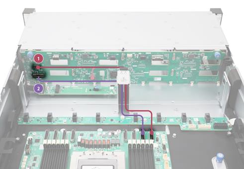
|
No. |
Cable type |
Cable code |
Description |
|
1 |
NVMe data cable |
0404A2BG |
From connectors NVME A3 and NVME A4 on the front backplane to connector C1-P3C on the storage controller. |
|
2 |
NVMe data cable |
0404A2AS |
From connector NVME A1/A2 on the front backplane to connector C1-P3A on the storage controller. |
2. Connect a SAS/SATA cable for the 12LFF drives at the front.
Figure 67 Connecting a SAS/SATA cable for the 12LFF drives at the front
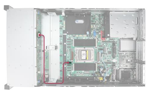
|
No. |
Cable type |
Cable code |
Description |
|
1 |
SAS/SATA data cable |
0404A2B7 |
From connector SAS PORT1 on the front drive backplane to connector C1-P0C on the system board |
3. Connect an AUX cable for the 12LFF drives at the front.
Figure 68 Connecting an AUX cable for the 12LFF drives at the front
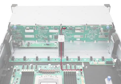
|
No. |
Cable type |
Description |
|
1 |
AUX cable |
From connector AUX1 on the front drive backplane to connector AUX1 on the system board |
4. Connect power cords for the 12LFF drives at the front.
Figure 69 Connecting power cords for the 12LFF drives at the front
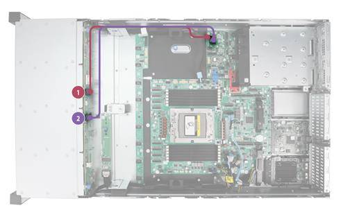
|
No. |
Cable type |
Description |
|
1 |
Power cord |
From connector PWR1 on the front drive backplane to connector PWR1 on the system board |
|
2 |
Power cord |
From connector PWR2 on the front drive backplane to connector PWR2 on the system board |
12LFF drives at the front + 2SFF UniBay drives at the rear
1. Connect SAS/SATA data cables for the 12LFF drives at the front.
Figure 70 Connecting an SAS/SATA data cable for the 12LFF drives at the front
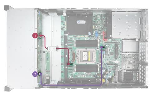
|
No. |
Cable type |
Cable code |
Description |
|
1 |
SAS/SATA data cable |
0404A2B7 |
From connector SAS PORT1 on the front backplane to connector C1-P0C on the storage controller. |
|
2 |
SAS/SATA data cable |
0404A2AW |
From connector SAS PORT2 on the front backplane to connector C1-G3A on the storage controller. |
2. Connect an AUX cable for the 12LFF drives at the front.
Figure 71 Connecting an AUX cable for the 12LFF drives at the front
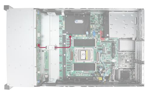
|
No. |
Cable type |
Cable code |
Description |
|
1 |
AUX cable |
From connector AUX1 on the front drive backplane to connector AUX1 on the system board |
|
3. Connect power cords for the 12LFF drives at the front.
Figure 72 Connecting power cords for the 12LFF drives at the front
|
No. |
Cable type |
Description |
|
1 |
Power cord |
From connector PWR1 on the front drive backplane to connector PWR1 on the system board |
|
2 |
Power cord |
From connector PWR2 on the front drive backplane to connector PWR2 on the system board |
4. Connect an NVME data cable for the 2SFF UniBay drives at the rear.
Figure 73 Connecting an NVME data cable for the 2SFF UniBay drives at the rear
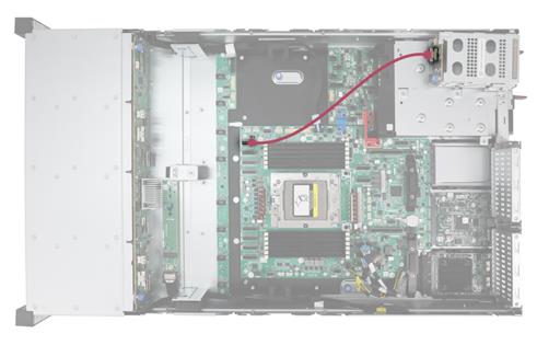
|
No. |
Cable type |
Cable code |
Description |
|
1 |
NVMe data cable |
0404A2AL |
From connector NVME on the front drive backplane to connector C1-P3C on the system board |
5. Connect an AUX data cable for the 2SFF UniBay drives at the rear.
Figure 74 Connecting an AUX data cable for the 2SFF UniBay drives at the rear
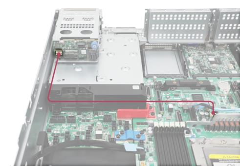
|
No. |
Cable type |
Description |
|
1 |
AUX cable |
From connector AUX on the front drive backplane to connector AUX5 on the system board |
6. Connect a power cord for the 2SFF UniBay drives at the rear.
Figure 75 Connecting a power cord for the 2SFF UniBay drives at the rear
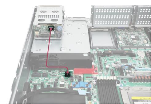
|
No. |
Cable type |
Description |
|
1 |
Power cord |
From connector PWR on the front drive backplane to connector PWR5 on the system board |
12LFF (4 SAS/SATA + 8 UniBay, LSI Expander) drives at the front
1. Connect NVMe data cables for the 12LFF drives at the front.
Figure 76 Connecting NVMe data cables for the 12LFF drives at the front
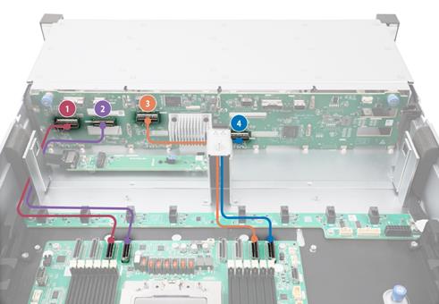
|
No. |
Cable type |
Cable code |
Description |
|
1 |
NVMe data cable |
0404A2B3 |
From connector NVME A1/A2 on the front drive backplane to connector C1-P0A on the system board |
|
2 |
NVMe data cable |
0404A2AQ |
From connector NVME A3/A4 on the front drive backplane to connector C1-P0C on the system board |
|
3 |
NVMe data cable |
0404A1PW |
From connector NVME B1/B2 on the front drive backplane to connector C1-P3A on the system board |
|
4 |
NVMe data cable |
0404A2B4 |
From connector NVME B3/B4 on the front drive backplane to connector C1-P3C on the system board |
2. Connect an SAS/SATA data cable for the 12LFF drives at the front.
Figure 77 Connecting an SAS/SATA data cable for the 12LFF drives at the front
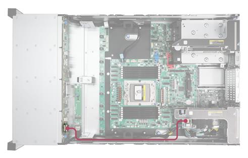
|
No. |
Cable type |
Cable code |
Description |
|
1 |
SAS/SATA data cable |
0404A1RQ |
From connector SAS PORT on the front drive backplane to connector C0 on the storage controller |
3. Connect power cords and an AUX cable for the 12LFF drives at the front.
Figure 78 Connecting AUX cables for the 12LFF drives at the front
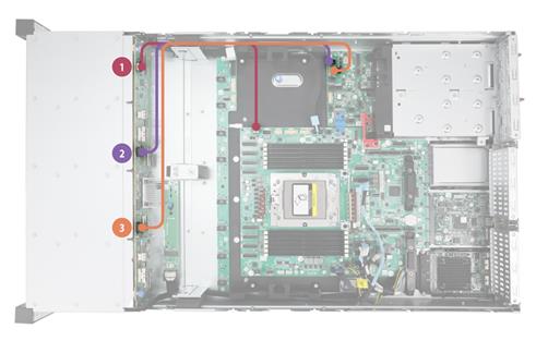
|
No. |
Cable type |
Description |
|
1 |
AUX cable |
From connector AUX on the front drive backplane to connector AUX1 on the system board |
|
2 |
Power cord |
From connector PWR1 on the front drive backplane to connector PWR1 on the system board |
|
3 |
Power cord |
From connector PWR2 on the front drive backplane to connector PWR2 on the system board |
8SFF UniBay+8SFF UniBay+8SFF UniBay drives at the front
1. Connect NVMe data cables for the 8SFF UniBay+8SFF UniBay+8SFF UniBay drives at the front.
Figure 79 Connecting NVMe data cables for 8SFF UniBay+8SFF UniBay+8SFF UniBay drives at the front
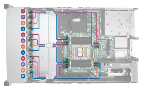
|
No. |
Cable type |
Cable code |
Description |
|
1 |
NVMe data cable |
0404A1PW |
From connector NVME B1/B2 on the front drive backplane to connector C1-G3A on the system board |
|
2 |
NVMe data cable |
0404A1PW |
From connector NVME B3/B4 on the front drive backplane to connector C1-G3C on the system board |
|
3 |
NVMe data cable |
0404A1WY |
From connector NVME A3/A4 on the front drive backplane to connector C1-P3C on the system board |
|
4 |
NVMe data cable |
0404A2B4 |
From connector NVME A1/A2 on the front drive backplane to connector C1-P3A on the system board |
|
5 |
NVMe data cable |
0404A20K |
From connector NVME B3/B4 on the front drive backplane to connector C1-P2C on the system board |
|
6 |
NVMe data cable |
0404A1YV |
From connector NVME B1/B2 on the front drive backplane to connector C1-P2A on the system board |
|
7 |
NVMe data cable |
0404A20K |
From connector NVME A3/A4 on the front drive backplane to connector C1-P0C on the system board |
|
8 |
NVMe data cable |
0404A2B4 |
From connector NVME A1/A2 on the front drive backplane to connector C1-P0A on the system board |
|
9 |
NVMe data cable |
0404A2AQ |
From connector NVME B3/B4 on the front drive backplane to connector C1-P1C on the system board |
|
10 |
NVMe data cable |
0404A2AQ |
From connector NVME B1/B2 on the front drive backplane to connector C1-P1A on the system board |
|
11 |
NVMe data cable |
0404A20K |
From connector NVME A3/A4 on the front drive backplane to connector C1-G1C on the system board |
|
12 |
NVMe data cable |
0404A20K |
From connector NVME A1/A2 on the front drive backplane to connector C1-G1A on the system board |
2. Connect AUX cables for the 8SFF UniBay+8SFF UniBay+8SFF UniBay drives at the front.
Figure 80 Connecting AUX cables for 8SFF UniBay+8SFF UniBay+8SFF UniBay drives at the front
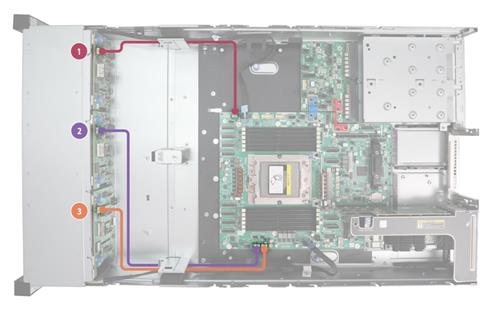
|
No. |
Cable type |
Description |
|
1 |
AUX cable |
From connector AUX on the front drive backplane to connector AUX1 on the system board |
|
2 |
AUX cable |
From connector AUX on the front drive backplane to connector AUX2 on the system board |
|
3 |
AUX cable |
From connector AUX on the front drive backplane to connector AUX3 on the system board |
3. Connect power cords for the 8SFF UniBay+8SFF UniBay+8SFF UniBay drives at the front.
Figure 81 Connecting AUX cables for 8SFF UniBay+8SFF UniBay+8SFF UniBay drives at the front
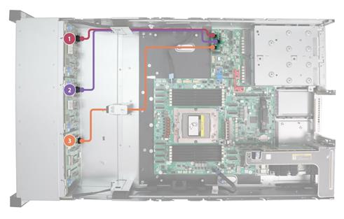
|
No. |
Cable type |
Description |
|
1 |
Power cord |
From connector PWR on the front drive backplane to connector PWR 1 on the system board |
|
2 |
Power cord |
From connector PWR on the front drive backplane to connector PWR 2 on the system board |
|
3 |
Power cord |
From connector PWR on the front drive backplane to connector PWR 2 on the system board |
25SFF (17 SAS/SATA + 8 UniBay) drives at the front
1. Connect NVMe data cables for the 25SFF drives at the front.
Figure 82 Connecting NVMe data cables for the 25SFF drives at the front

|
No. |
Cable type |
Cable code |
Description |
|
1 |
NVMe data cable |
0404A2BF |
From connector NVME1 on the front drive backplane to connector C1-P0A on the system board |
|
2 |
NVMe data cable |
0404A2AQ |
From connector NVME2 on the front drive backplane to connector C1-P0C on the system board |
|
3 |
NVMe data cable |
0404A2BG |
From connector NVME3 on the front drive backplane to connector C1-P3A on the system board |
|
4 |
NVMe data cable |
0404A2BG |
From connector NVME4 on the front drive backplane to connector C1-P3C on the system board |
2. Connect an SAS/SATA cable for 25SFF drives at the front.
Figure 83 Connecting an SAS/SATA cable for 25SFF drives at the front
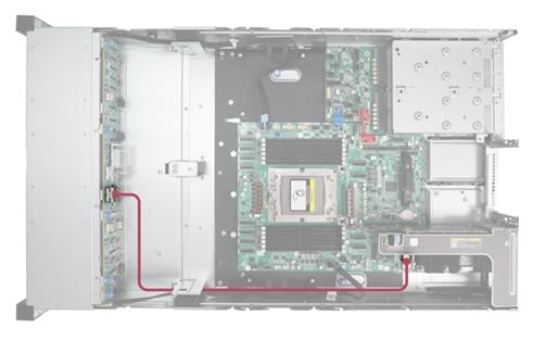
|
No. |
Cable type |
Cable code |
Description |
|
1 |
SAS/SATA cable |
0404A1QM |
From connector SAS PORT1 on the front drive backplane to connector C0 on the storage controller |
3. Connect an AUX cable for the 25SFF drives at the front.
Figure 84 Connecting an AUX cable for the 25SFF drives at the front
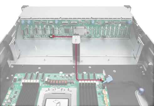
|
No. |
Cable type |
Description |
|
1 |
AUX cable |
From connector AUX on the front drive backplane to connector AUX1 on the system board |
4. Connect power cords for the 25SFF drives at the front.
Figure 85 Connecting power cords for the 25SFF drives at the front
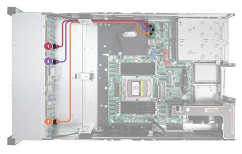
|
No. |
Cable type |
Description |
|
1 |
Power cord |
From connector PWR1 on the front drive backplane to connector PWR1 on the system board |
|
2 |
Power cord |
From connector PWR2 on the front drive backplane to connector PWR2 on the system board |
|
3 |
Power cord |
From connector PWR3 on the front drive backplane to connector PWR3 on the system board |
Connecting the LCD smart management module cable
Figure 86 Connecting the LCD smart management module cable
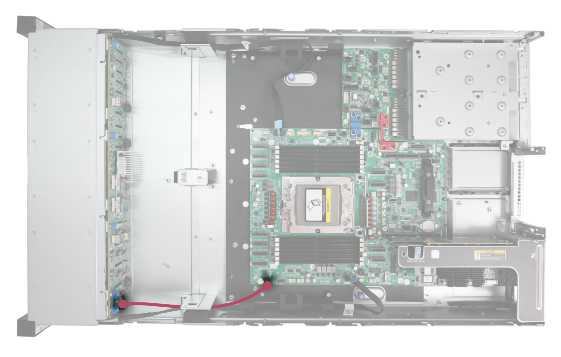
|
No. |
Cable type |
Cable code |
Description |
|
1 |
Signal cable |
0404A1BN |
From the LCD smart management module to connector DIAG LCD on the system board |
Connecting cables for the front M.2 SSD expander module
Figure 87 Connecting cables for the front M.2 SSD expander module
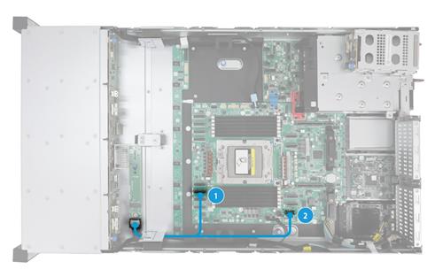
|
No. |
Cable type |
Cable code |
Description |
|
1、2 |
SAS/SATA/NVMe data & AUX cable |
0404A2BE |
· From connector M.2 PORT on the M.2 SSD expander module to connector C1-P0A on the system board · From connector M.2 PORT on the M.2 SSD expander module to connector M.2 AUX(FRONT) on the system board |
Connecting cables for OCP 3.0 network adapter 1
OCP 3.0 network adapter 1 supports cables with cable codes as 0404A1YH and 0404A1YM. Figure 88 connects cable 0404A1YH for OCP 3.0 network adapter 1 as an example. For information about how to connect cables for OCP network adapters in other slots, contact Technical Support.
Figure 88 Connecting cables for OCP 3.0 network adapter 1
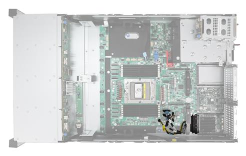
|
Cable type |
Cable code |
Description |
|
0404A1YH |
From the end with label M1 to connector OCP1 AUX on the system board |
|
|
From the end with label M2 to connector OCP1 PWR on the system board |
||
|
From the end with label M3 to connector C1-G1A on the system board |
||
|
From the end with label M4 to connector C1-G1C on the system board |
||
|
OCP 3.0 network adapter 1 cable |
0404A1YM |
From the end with label M1 to connector OCP1 AUX on the system board. This cabling scheme is available only when 24 NVMe drives are installed |
|
From the end with label M2 to connector OCP1 PWR on the system board. This cabling scheme is available only when 24 NVMe drives are installed |
||
|
From the end with label M3 to connector RISER1 PCIe x16 on the system board. This cabling scheme is available only when 24 NVMe drives are installed. |
Connecting cables for riser cards
Some riser cards can provide additional PCIe links for the slots on the card by connecting to the system board. This section introduces the cabling schemes for these riser cards. For detailed information about PCIe riser connectors, see "Riser cards and PCIe modules."
For information about PCIe riser bay numbering, see "Rear panel view." The cabling schemes are similar for these riser cards and this section connects cables for PCIe riser connectors 3 and 4 as an example.
Figure 89 Connecting cables for an HHHL riser 3 assembly module
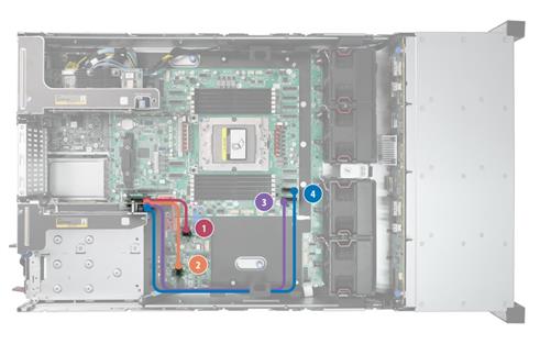
|
Riser connector |
No. |
Cable type |
Cable code |
Description |
|
Riser3 |
1 |
PWR |
0404A2AJ (two cables) |
From the end with label S2 of the PWR cable in slot 7 to connector PWR6 on the system board |
|
2 |
PCIe |
From the end with label S1 of the PCIe cable in slot 7 to connector C1-P3C on the system board |
||
|
3 |
PWR |
From the end with label S2 of the PWR cable in slot 8 to connector PWR7 on the system board |
||
|
4 |
PCIe |
From the end with label S1 of the PCIe cable in slot 8 to connector C1-P3A on the system board |
Figure 90 Connecting cables for an FHFL riser 4 assembly module
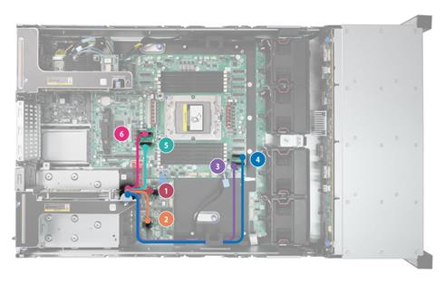
|
Riser connector |
No. |
Cable type |
Cable code |
Description |
|
Riser4 |
1 |
PWR |
0404A2BC (slot9) + 0404A1YG (slot 10) |
From the end with label S3 of the PWR cable in slot 9 to connector PWR7 on the system board |
|
2 |
PCIe |
From the end with label S1 of the PCIe cable in slot 9 to connector C1-P3A on the system board |
||
|
3 |
PCIe |
From the end with label S2 of the PCIe cable in slot 9 to connector C1-P3C on the system board |
||
|
4 |
PWR |
From the end with label S3 of the PWR cable in slot 10 to connector PWR6 on the system board |
||
|
5 |
PCIe |
From the end with label S1 of the PCIe cable in slot 10 to connector C1-G3A on the system board |
||
|
6 |
PCIe |
From the end with label S2 of the PCIe cable in slot 10 to connector C1-G3C on the system board |
Connecting the supercapacitor cable
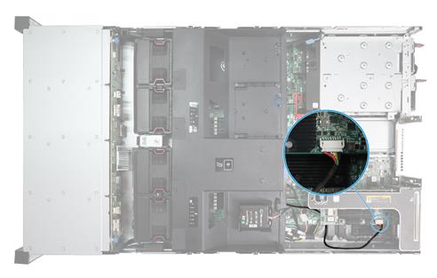
Connecting chassis ear cables
Figure 91 Connecting chassis ear cables
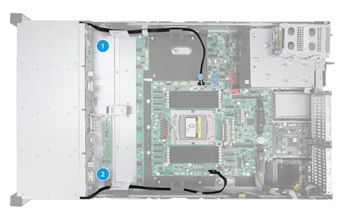
|
(1) Left chassis ear cable |
(2) Right chassis ear cable |
Maintenance
The following information describes the guidelines and tasks for daily server maintenance.
Guidelines
· Keep the equipment room clean and tidy. Remove unnecessary devices and objects from the equipment room.
· Make sure the temperature and humidity in the equipment room meet the server operating requirements.
· Regularly check the server from HDM for operating health issues.
· Keep the operating system and software up to date as required.
· Make a reliable backup plan:
¡ Back up data regularly.
¡ If data operations on the server are frequent, back up data as needed in shorter intervals than the regular backup interval.
¡ Check the backup data regularly for data corruption.
· Stock spare components on site in case replacements are needed. After a spare component is used, prepare a new one.
· Keep the network topology up to date to facilitate network troubleshooting.
Maintenance tools
The following are major tools for server maintenance:
· Hygrothermograph—Monitors the operating environment of the server.
· HDM and UniSystem—Monitors the operating status of the server.
Maintenance tasks
This section describes the routine maintenance tasks and operation methods of the server.
Task list
Table 36 lists the routine maintenance tasks.
|
Task |
Maintenance tools |
|
/ |
|
|
Monitoring the temperature and humidity in the equipment room |
hygrothermograph |
|
/ |
Observing LED status
Observe the LED status on the front and rear panels of the server to verify that the server modules are operating correctly. For more information about the status of the front and rear panel LEDs, see "LEDs and buttons" and "LEDs."
Monitoring the temperature and humidity in the equipment room
Use a hygrothermograph to monitor the temperature and humidity in the equipment room.
The temperature and humidity in the equipment room must meet the server requirements described in "Technical specifications."
Examining cable connections
Verify that the cables and power cords are correctly connected.
Guidelines
· Do not use excessive force when connecting or disconnecting cables.
· Do not twist or stretch the cables.
· Organize the cables appropriately. For more information, see "Cabling guidelines."
Checklist
· The cable type is correct.
· The cables are correctly and firmly connected and the cable length is appropriate.
· The cables are in good condition and are not twisted or corroded at the connection point.
Viewing server status
To view basic information and status of the subsystems of the server, see "System status" in H3C Servers HDM2 Online Help.
Collecting server logs
For the procedure for collecting server logs, see log downloading in H3C Servers HDM2 User Guide.
Updating firmware for the server
For the procedure for updating the HDM firmware, BIOS, or CPLD, see H3C Servers Firmware Update Guide.
Troubleshooting
See the troubleshooting guide.
