- Table of Contents
-
- 04-Network Configuration
- 01-Access Public and Dedicated Networks Through Multiple WAN Interfaces (CLI)
- 02-Basic Network Access (DHCP-Based IP Address Acquisition) Configuration Examples (CLI)
- 03-ER G3 Routers PPPoE Configuration Examples (Web)
- 04-ER G3 Routers Basic Network Access (DHCP-Based IP Address Acquisition) (Web)
- 05-ER G3 Routers Basic Internet Access (Static IP) Web-Based Configuration Examples
- 06-MER Routers Basic Network Access (DHCP-Based IP Address Acquisition) (Web)
- 07-MER Routers Primary and Backup Network Accesses Through Multiple WAN Interfaces (Web)
- 08-MER Routers PPPoE Configuration Examples (Web)
- 09-MER Routers Access Public and Dedicated Networks Through Multiple WAN Interfaces (Web)
- 10-MER Routers Basic Internet Access (Static IP) Web-Based Configuration Examples
- 11-MSR Routers Basic Network Access (DHCP-Based IP Address Acquisition) (Web)
- 12-MSR Routers Basic Internet Access (Static IP) Web-Based Configuration Examples
- 13-MSR Routers Access Public and Dedicated Networks Through Multiple WAN Interfaces (Web)
- 14-MSR Routers PPPoE Configuration Examples (CLI)
- 15-Router Basic Internet Access (Static IP) CLI-Based Configuration Examples
- Related Documents
-
| Title | Size | Download |
|---|---|---|
| 05-ER G3 Routers Basic Internet Access (Static IP) Web-Based Configuration Examples | 883.31 KB |
ERG3 Routers
Basic Internet Access (Static IP) Web-Based Configuration Examples
Copyright © 2024 New H3C Technologies Co., Ltd. All rights reserved.
No part of this manual may be reproduced or transmitted in any form or by any means without prior written consent of Hangzhou H3C Technologies Co., Ltd.
Except for the trademarks of New H3C Technologies Co., Ltd., any trademarks that may be mentioned in this document are the property of their respective owners.
The information in this document is subject to change without notice.
Introduction
The following information provides an example of the Web-based configuration for basic Internet access (static IP) on an ERG3 router.
Prerequisites
Procedures and information in the document might be slightly different depending on the software or hardware version of the device.
The configuration examples were created and verified in a lab environment, and all the devices were started with the factory default configuration. When you are working on a live network, make sure you understand the potential impact of every command on your network.
The following information is provided based on the assumption that you have basic knowledge of DHCP and NAT.
Example: Configuring basic Internet access settings (static IP) for the router
Network configuration
As shown in Figure 1, the device acts as the enterprise network's egress router, with all external interface modes set to single-WAN mode. Configure Internet access through a static IP address. Configure the router for the user's PC to access the Internet through the router.

Software versions used
This example applies to Comware 7-based ERG3 series routers. This configuration example was created and verified on R0136 of the H3C ER3200G3. Specific operations might vary slightly depending on the product model and software version.
Restrictions and guidelines
The address range of the address pool specified on the LAN interface cannot be in the same subnet as the WAN interface IP address on the device.
Procedures
You can use either of the following methods to configure Internet access:
· Quick configuration: Supports key parameter configuration for both single-WAN and dual-WAN scenarios, achieving rapid Internet access. This configuration method is simple and suitable for general Internet usage needs.
· Network settings: Support configuration for single-WAN, dual-WAN, and multi-WAN scenarios with a richer array of parameters. This configuration method suits scenarios with higher network requirements, allowing for more customized settings to optimize network performance.
Quick configuration
Configuring the WAN access scenario
In this example, the router is set up in single-WAN mode, and the configuration steps are as follows:
1. Log in to the router's Web management interface and click Quick Config from the left navigation pane.
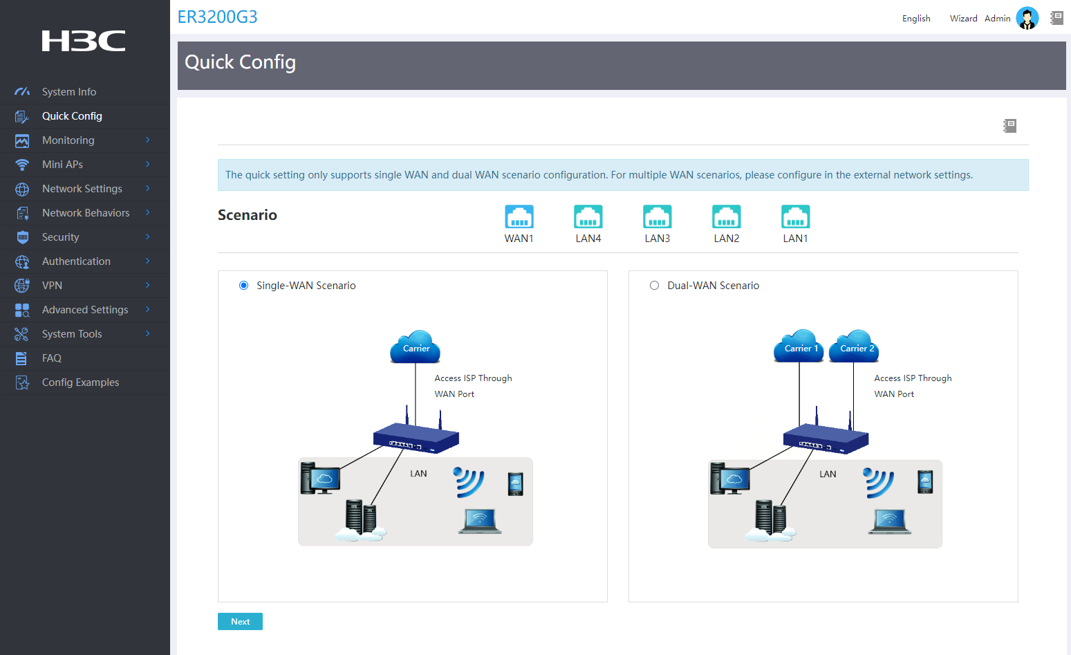
2. Enter the scenario selection configuration page and select the single-WAN scenario.
3. Click Next.
Figure 2 Scenario selection
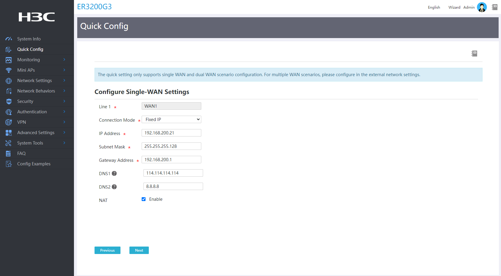
Configuring WAN interface parameters
1. Select Fixed IP from the Connection Mode field.
2. Enter static IP address 192.168.200.21 in the IP Address field.
3. Enter subnet mask 255.255.255.128 for the IP address in the Subnet Mask field.
4. Enter gateway address 192.168.200.1 in the Gateway Address field.
5. Enter DNS server addresses 114.114.114.114 and 8.8.8.8 in the DNS1 and DNS2 fields, respectively.
6. Enable NAT.
7. Click Next.
Figure 3 Single WAN configuration
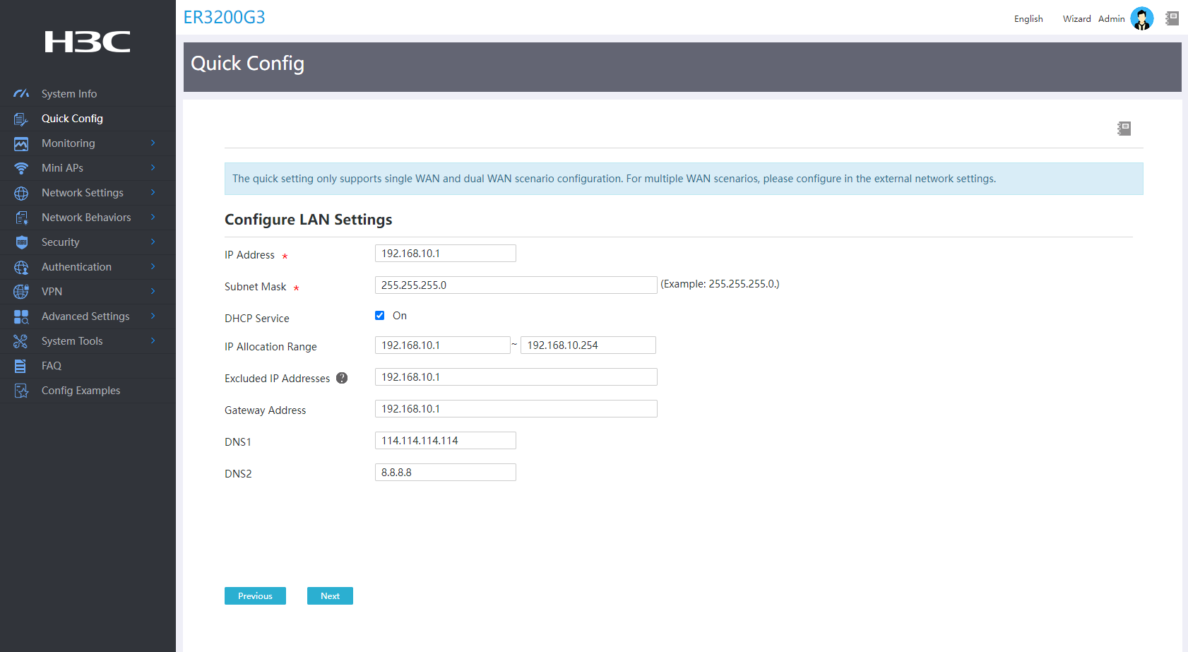
Configuring LAN interface parameters
1. Specify the LAN IP address as 192.168.10.1 and the subnet mask as 255.255.255.0.
2. Enable the DHCP service.
3. Configure the DHCP service address range for allocation as 192.168.10.1 to 192.168.10.254.
4. Specify excluded addresses as needed to prevent the device from assigning certain IP addresses within the address pool range (such as gateway addresses) to clients. In this example, exclude the gateway address 192.168.10.1 from client IP address allocation.
5. Enter DNS server addresses 114.114.114.114 and 8.8.8.8 in the DNS1 and DNS2 fields, respectively.
6. Click Next.
Figure 4 LAN configuration
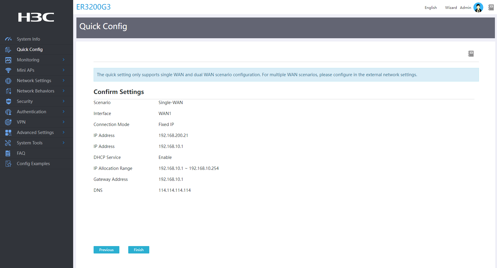
Saving the configuration
Click Finish to save the quick settings.
Figure 5 Saving the configuration
Network settings
Configuring the interface mode
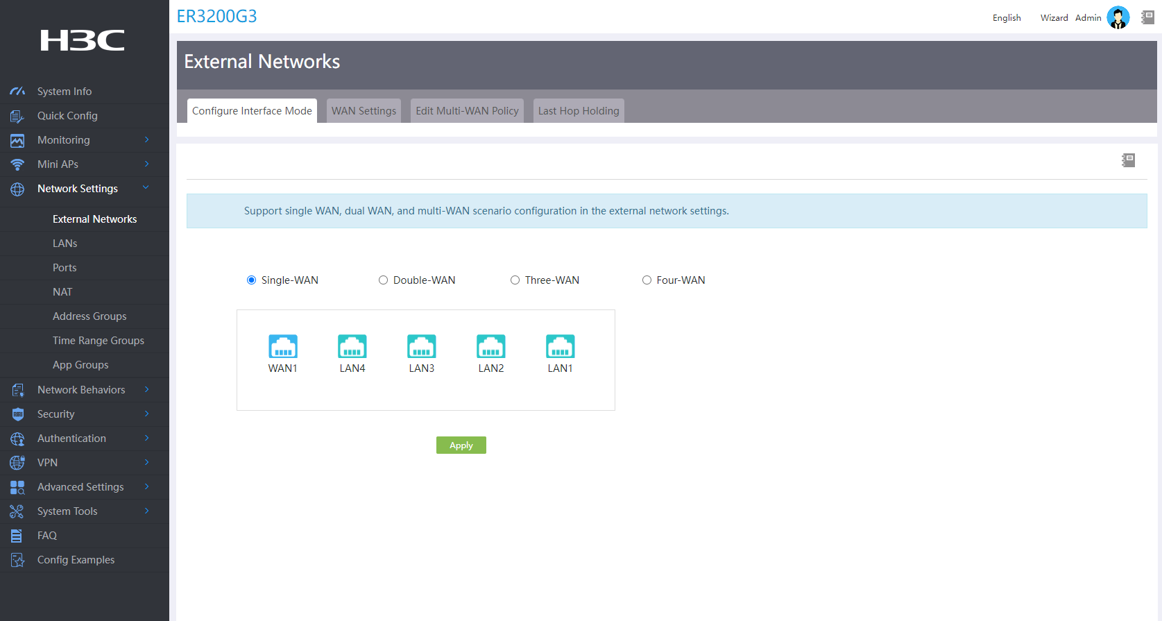
1. Log in to the router's Web management interface and select Network Settings > External Networks from the left navigation pane.
2. Click the Configure Interface Mode tab and select the Single-WAN mode.
3. Click Apply.
Figure 6 Configuring the interface mode
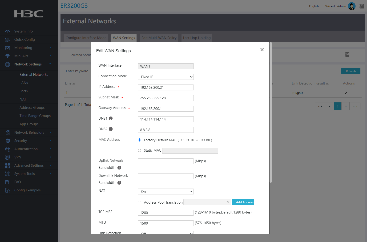
Configuring WAN interface parameters
1. Click the WAN Settings tab.
2. Click the Edit icon in the Actions column for the WAN1 interface.
3. Select Fixed IP from the Connection Mode field and configure the following parameters:
¡ Enter static IP address 192.168.200.21 in the IP Address field.
¡ Enter subnet mask 255.255.255.128 for the IP address in the Subnet Mask field.
¡ Enter gateway address 192.168.200.1 in the Gateway Address field.
¡ Enter DNS server addresses 8.8.8.8 and 114.114.114.114 in the DNS1 and DNS2 fields, respectively.
¡ Enter the interface MAC address In the MAC Address field. You can use the default factory MAC address of the interface because the ISP does not require MAC address binding.
¡ Enable NAT address translation.
¡ Set the maximum size for a TCP segment and MTU permitted by the interface in the TCP MSS and MTU fields. In this example, the default settings are used.
4. Retain the default settings in the other fields and then click Apply.
Figure 7 Changing WAN configuration
Configuring LAN interface parameters
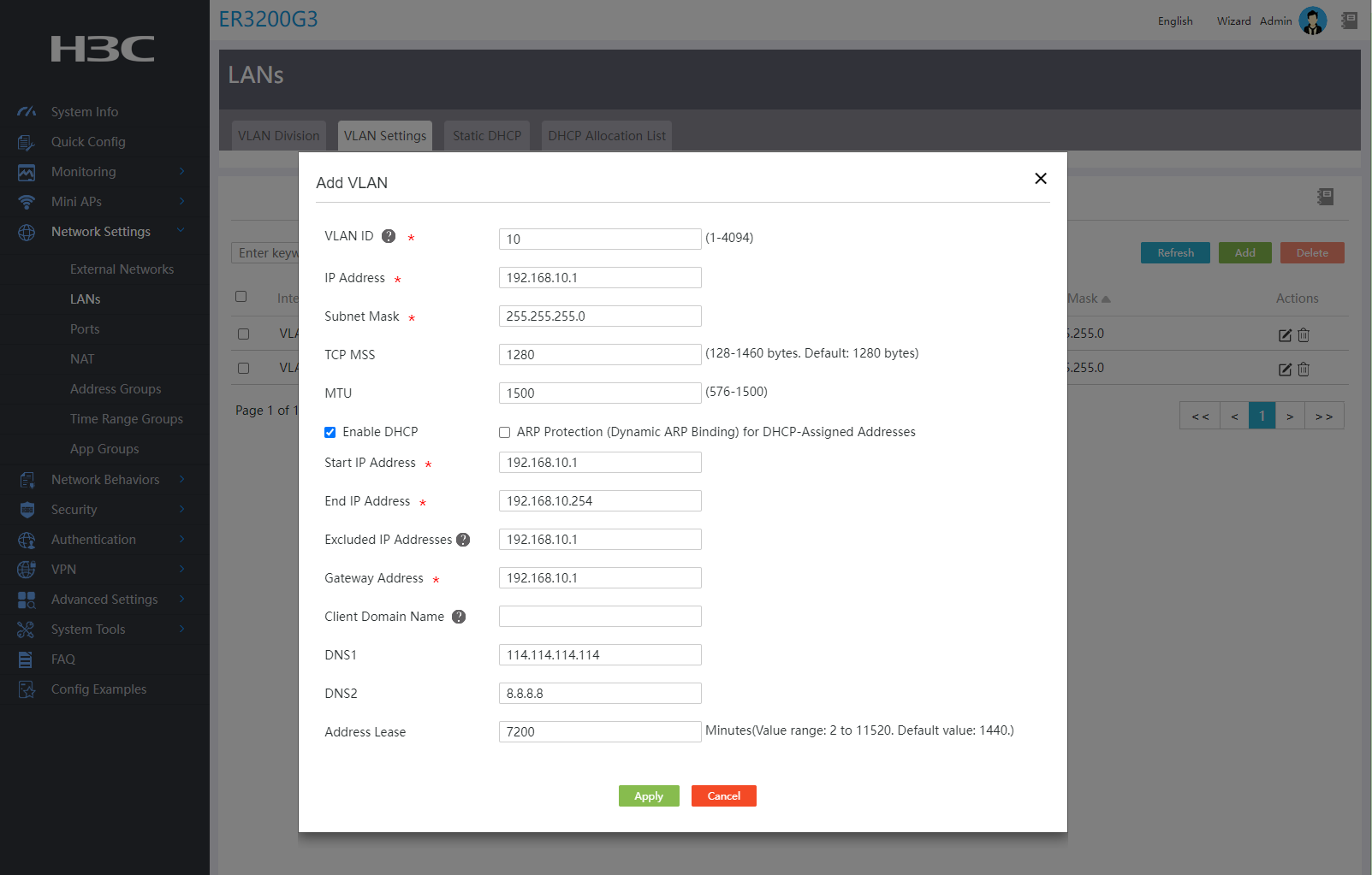
# Configure VLAN 10 on the router with the VLAN-interface IP address set to 192.168.10.1. The configuration steps are as follows:
1. From the left navigation pane, select Network Settings > LANs. Click the VLAN Settings tab.
2. Click Add.
3. Enter 10 as the VLAN ID.
4. Specify 192.168.10.1 as the IP address.
5. Specify 255.255.255.0 as the subnet mask.
6. Set the TCP MSS to 1280 and the interface MTU to 1500.
7. Enable the DHCP service on the VLAN interface and configure the following parameters:
¡ Specify start address 192.168.10.1 and end address 192.168.10.254 for the address pool.
¡ Specify excluded addresses as needed to prevent the device from assigning certain IP addresses within the address pool range (such as gateway addresses) to clients. In this example, exclude the gateway address 192.168.10.1 from client IP address allocation.
¡ Enter the client gateway address as 192.168.10.1.
¡ Enter DNS server addresses 114.114.114.114 and 8.8.8.8 in the DNS1 and DNS2 fields, respectively.
¡ Set the IP address lease in minutes. For example, to set the IP address lease to 5 days, enter 7200.
8. Retain the default settings in the other fields and then click Apply.
Figure 8 Adding a VLAN configuration
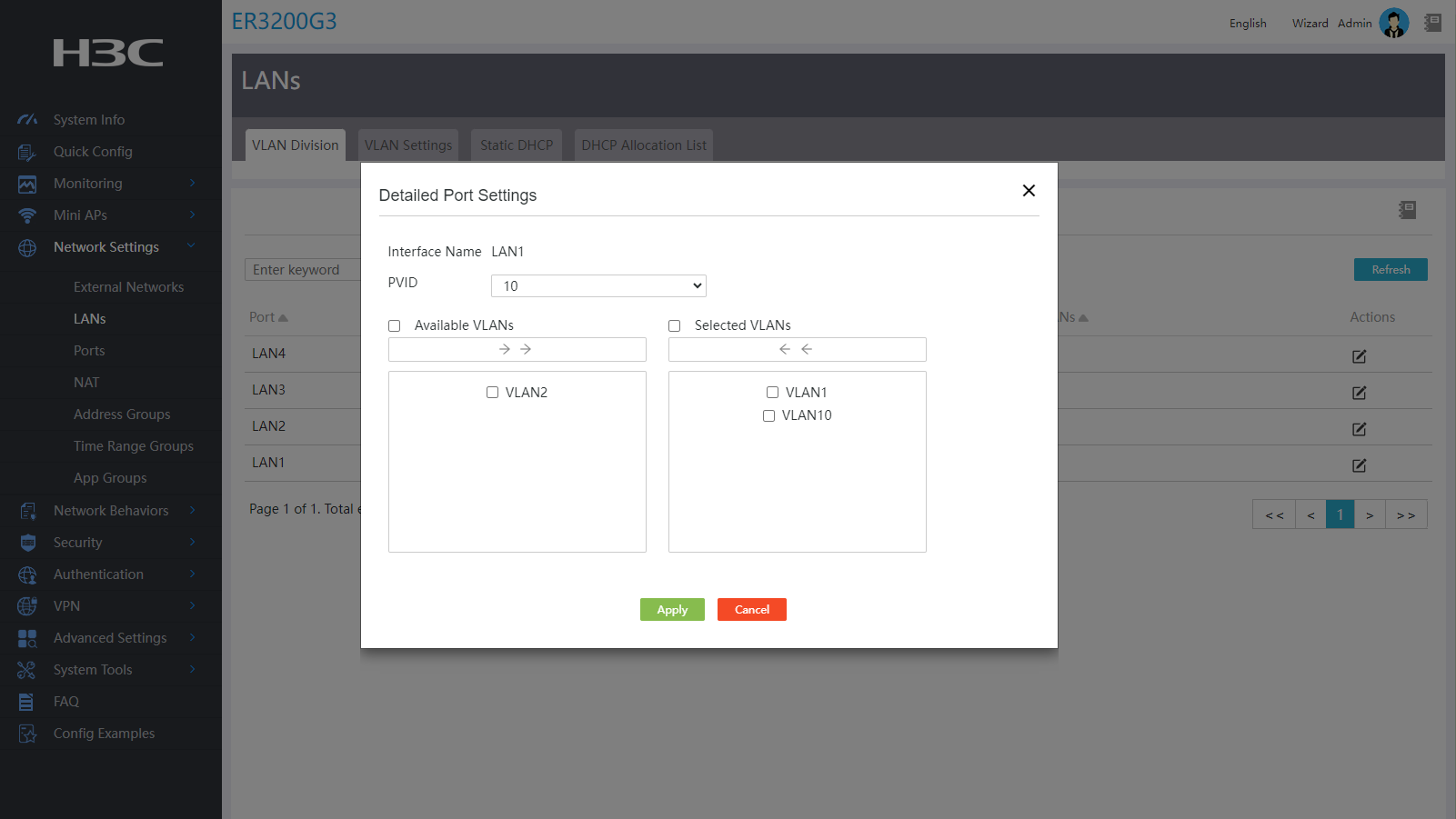
# Add the LAN1 interface to VLAN 10.
1. From the left navigation pane, select Network Settings > LANs.
2. Click the Edit icon in the Actions column for interface LAN1. The interface configuration page opens.
3. Enter 10 as the PVID.
4. Click Apply.
Figure 9 Assigning the LAN interface to the designated VLAN
Verifying the configuration
Verify that the PC can access the Internet.