- Table of Contents
- Related Documents
-
| Title | Size | Download |
|---|---|---|
| 01-Text | 7.03 MB |
Hardware requirements (deployment on physical server)
Hardware requirements (deployment on VM)
(Optional.) Configure network settings
Plan the IP address assignment scheme
Deploy the simulation device host in standalone mode
Kylin V10SP02 operating system
Configure the simulation device hosts
Deploy the simulation device host in convergence mode
Deploy virtualization simulation device hosts
Deploy DTN over a Layer 3 network
Configure basic simulation service settings
Preconfigure the simulation network
Install the activation file on the license server
Obtain simulation device licenses
Back up and restore the DTN configuration
Upgrade and uninstall software
Upgrade the simulation device hosts
Upgrade the simulation device host deployed in standalone mode
Upgrade the virtualization simulation device host deployed in convergence mode
Uninstall the simulation device host
Uninstall the simulation device host deployed in standalone mode
Uninstall the virtualization simulation device host deployed in convergence mode
Introduction
In the DC scenario, the SeerEngine-DC services are complicated, and hard to operate. After complicated operations, you might fail to achieve the expected results. As a result, a large number of human and material resources are wasted. Therefore, it is necessary to perform a rehearsal before deploying actual services. During the rehearsal process, you can learn and avoid risks, so that you can reduce the risk possibilities for the production environment to the maximum extent. The simulation function is introduced for this purpose. The simulation function simulates a service and estimates resource consumption before you deploy the service. It helps users to determine whether the current service orchestration can achieve the expected effect and affect existing services, and estimate the device resources to be used.
The simulation function provides the following features:
· Simulation network—The simulation network model is built in a 1:1 ratio to the real network through vSwitches. The simulation system is built based on the simulation network model, which needs highly automated management.
· Tenant service simulation—This function mainly orchestrates and configures the logical network and application network. This function simulates a service and estimates resource consumption before you deploy the service. It helps users to determine whether the current service orchestration can achieve the expected effect and affect existing services. This function includes capacity simulation, connectivity simulation, and network-wide impact analysis. You can deploy the service configuration to real devices when the simulation evaluation result is as expected.
· Data synchronization with the production environment—Synchronizes specific configuration data in the production environment to the simulation environment.
· Simulation records—Displays the simulation records of users and provides the advanced search function.
This document describes how to deploy the DTN component, simulation device hosts and build a simulation network on the controller.
Prepare for installation
|
|
NOTE: · DTN component does not support RDRS deployment. · As a best practice, select the flavor named 1_cpu_4096MB_memory_2048MB_storage. The flavor named 1_cpu_2048MB_memory_2048MB_storage is applicable in the scenario where the number of each type of logical resources (vRouters, vNetworks, or vSubnets) is not greater than 1000. |
Server requirements
The following deployment modes are available for the DTN component and simulation device host:
· Standalone deployment of the DTN component—Installs the DTN component separately on a worker node.
· Convergence deployment of the virtualization simulation device host—Deploys the virtualization simulation device host together with the controller or the DTN component on the same master or worker node.
· Standalone deployment of the virtualization simulation device host—Installs the virtualization simulation device host separately on a worker node.
· Standalone deployment of the simulation device host—Deploys the simulation device host separately on either a physical server or a VM.
This document recommends deployment scenarios for simulation on the controller in cluster mode as an example.
Hardware requirements (deployment on physical server)
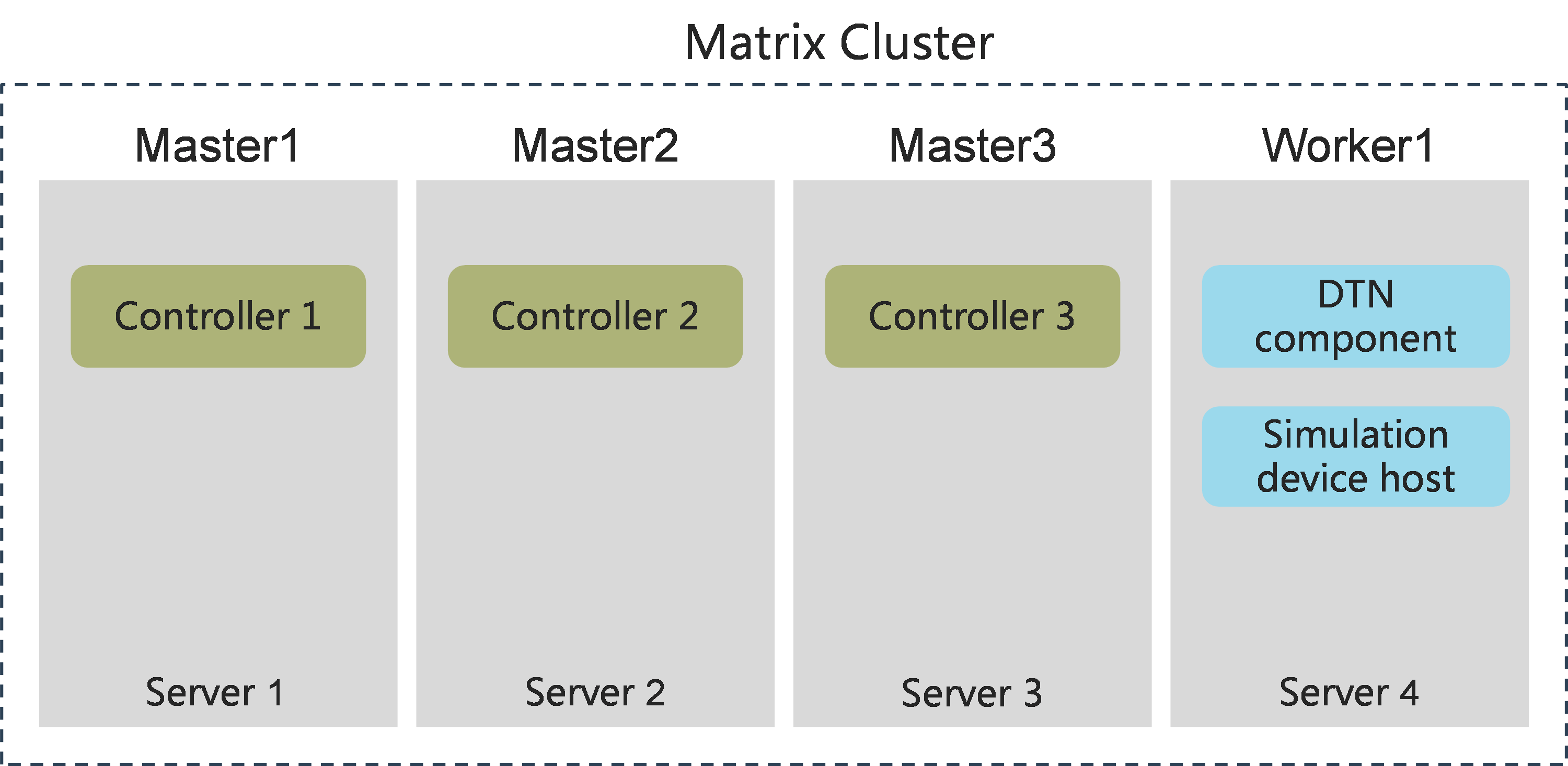
Recommended deployment scenario 1: Standalone deployment of the DTN component + convergence deployment of the simulation device host
Deploy the DTN component on a worker node. Deploy the virtualization simulation device host and DTN component on the same worker node.
Figure 1 Matrix cluster (standalone deployment of the DTN component + convergence deployment of the simulation device host)
Minimum hardware requirements:
Table 1 Hardware requirements for standalone deployment of the DTN component
|
Application name |
Hardware requirements |
Remarks |
|
DTN component |
Available CPU configuration options: · x86-64 (Intel64/AMD64): 16 cores, 2.0 GHz Memory: 128 GB Disk: · System drive: 1920 GB (after RAID setup) Network interfaces: · Non-bonding mode: 2 × 10Gbps · Bonding mode: 4 × 10 Gbps, with two network interfaces forming one Linux bonding interface |
This configuration applies only when the DTN component is deployed on a worker node If you have an ARM server, select recommended deployment scenario 2. |
Table 2 Hardware requirements for convergence deployment of the simulation device host
|
Application name |
Hardware requirements |
Remarks |
|
Simulated device host |
CPU (cores): · x86-64 (Intel64/AMD64): 8 Memory (GB): 64 Network interfaces: · Non-bonding mode: 1 × 10Gbps · Bonding mode: 2 × 10Gbps |
Add these configuration resources to the node where the simulation device host is deployed. ARM servers do not support the convergence deployment of simulation device hosts. Select recommended deployment scenario 2. Management scale · Simulated devices: 15 (1_cpu_4096MB_memory_2048MB_storage) · Simulated devices: 30 (1_cpu_2048MB_memory_2048MB_storage) |
|
Simulated device host |
CPU (cores): · x86-64 (Intel64/AMD64): 16 Memory (GB): 128 Network interfaces: · Non-bonding mode: 1 × 10Gbps · Bonding mode: 2 × 10Gbps |
Management scale · Simulated devices: 30 (1_cpu_4096MB_memory_2048MB_storage) · Simulated devices: 60 (1_cpu_2048MB_memory_2048MB_storage) |
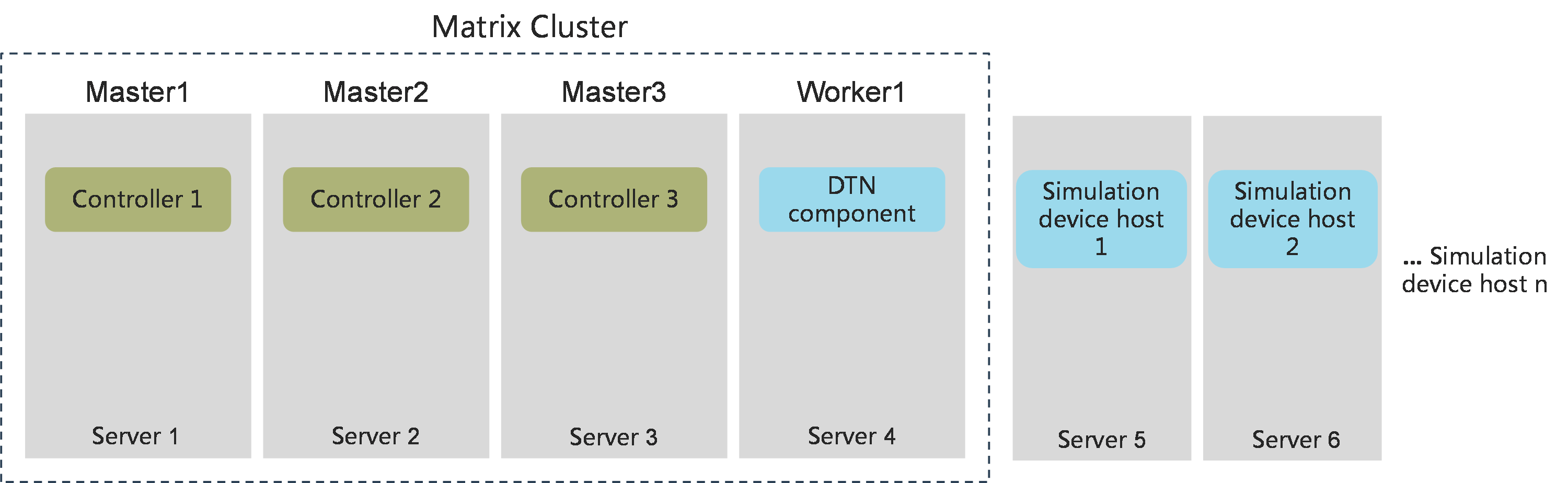
Recommended deployment scenario 2: Standalone deployment of the DTN component + standalone deployment of the simulation device host
Deploy the DTN component on a worker node. Deploy the simulation device host separately on a physical server.
Figure 2 Matrix cluster (standalone deployment of the DTN component + standalone deployment of the simulation device host)
Minimum hardware requirements:
Table 3 Hardware requirements for standalone deployment of the DTN component
|
Application name |
Hardware requirements |
Remarks |
|
DTN component |
Available CPU configuration options: · x86-64 (Intel64/AMD64): 16 cores, 2.0 GHz · x86-64 (Hygon): 32 cores, 2.5 GHz, 2 × (2 × Hygon G5 5380 16 cores) · ARM (Kunpeng): 48 cores, 2 × (Kunpeng 920, 24 cores, 2.6 GHz) · ARM (Phytium): 128 cores, 2 × (Phytium S2500, 64 cores, 2.1 GHz) Memory: 128 GB Disk: · System drive: 1920 GB (after RAID setup) Network interfaces: · Non-bonding mode: 2 × 10Gbps · Bonding mode: 4 × 10 Gbps, with two network interfaces forming one Linux bonding interface |
This configuration applies only when the DTN component is deployed on a worker node |
Table 4 Hardware requirements for standalone deployment of the simulation device host
|
Node name |
Node quantity |
Hardware node requirements |
Remarks |
|
Simulated device host |
n |
Available CPU configuration options: · x86-64 (Intel64/AMD64): 16 cores, 2.0 GHz · x86-64 (Hygon): 32 cores, 2 × (2 × Hygon G5 5380, 16 cores, 2.5 GHz) · ARM (Kunpeng): 48 cores, 2 × (Kunpeng 920, 24 cores, 2.6 GHz) · ARM (Phytium): 128 cores, 2 × (Phytium S2500, 64 cores, 2.1 GHz) Memory: 128 GB Disk: · System drive: 600GB (after RAID setup) Network interfaces: · Non-bonding mode: 3 × 10Gbps · Bonding mode: 6 × 10Gbps, with two network interfaces forming one Linux bonding interface |
Standard configuration Maximum management scale a single host supports: · Simulated devices: 30 (1_cpu_4096MB_memory_2048MB_storage) · Simulated devices: 60 (1_cpu_2048MB_memory_2048MB_storage) Use this formula to calculate n (the number of simulation device hosts): n=Total number of simulated devices/management scale |
|
Simulated device host |
n |
Available CPU configuration options: · x86-64 (Intel64/AMD64): 20 cores, 2.0 GHz · x86-64 (Hygon): 32 cores, 2 × (2 × Hygon G5 5380, 16 cores, 2.5 GHz) · ARM (Kunpeng): 48 cores, 2 × (Kunpeng 920, 24 cores, 2.6 GHz) · ARM (Phytium): 128 cores, 2 × (Phytium S2500, 64 cores, 2.1 GHz) Memory: 128 GB Disk: · System drive: 600GB (after RAID setup) Network interfaces: · Non-bonding mode: 3 × 10Gbps · Bonding mode: 6 × 10 Gbps, with two network interfaces forming one Linux bonding interface |
Recommended configuration Maximum management scale a single host supports: · Simulated devices: 80 (1_cpu_4096MB_memory_2048MB_storage) · Simulated devices: 160 (1_cpu_2048MB_memory_2048MB_storage) Use this formula to calculate n (the number of simulation device hosts): n=Total number of simulated devices/management scale |
Other optional deployment scenarios
Before deploying the following non-recommended scenarios, contact Technical Support to confirm the scenario specifications and related resource configuration requirements.
Table 5 Other optional deployment scenarios
|
Scenario |
Remarks |
|
Convergence deployment of the DTN component + standalone deployment of the simulated device host |
· Deploy the DTN component on a master node and add the hardware requirements of the DTN component on the master node. · Deploy the simulated device host separately on a physical server. |
|
Convergence deployment of the DTN component + convergence deployment of the simulated device host |
· Deploy the DTN component on a master node and add the hardware requirements of the DTN component on the master node. · Deploy the virtual simulated device host on the same master node as the DTN component. |
Hardware requirements (deployment on VM)
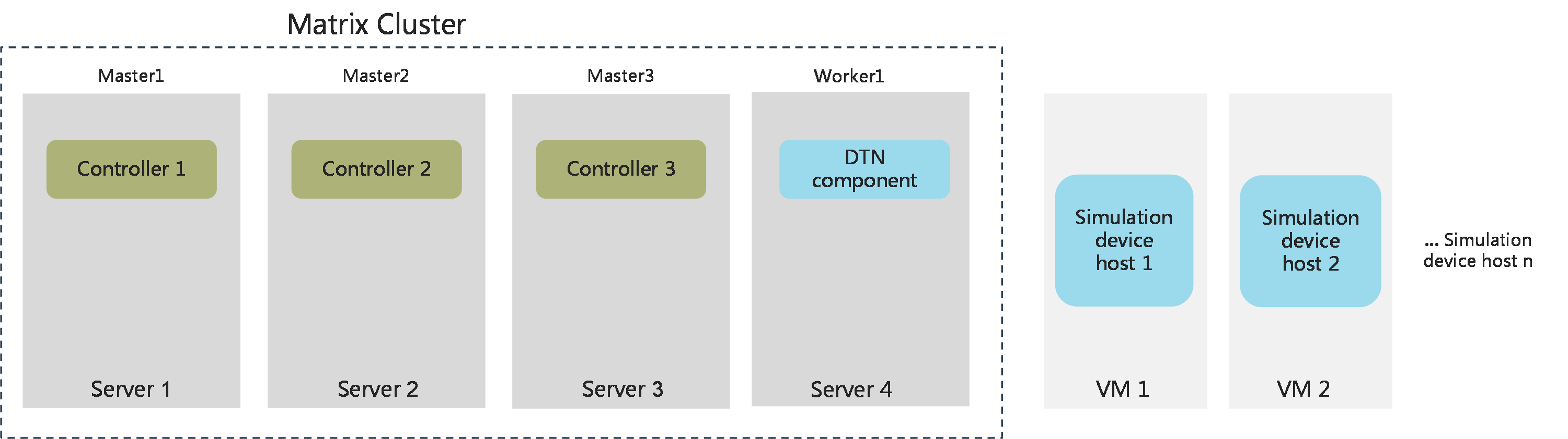
Recommended deployment scenario: Standalone deployment of the DTN component + standalone deployment of the simulation device host
Deploy the DTN component on the Worker node and deploy the simulation device host on a separate VM.
Figure 3 Matrix cluster (standalone deployment of the DTN component + standalone deployment of the simulation device host)
Minimum hardware requirements:
Table 6 Hardware requirements for standalone deployment of the DTN component
|
Node name |
Node quantity |
Hardware node requirements |
Remarks |
|
DTN component |
1 |
· vCPU: ¡ Intel/AMD CPU: ¡ Hygon CPU: ¡ Kunpeng CPU: 48 cores. 2.0 GHz ¡ Phytium CPU: 96 cores. 2.0 GHz · Memory: 128GB · Disk: ¡ System disk: 1.92TB, with a minimum of 5000 IOPS. ¡ ETCD: 50GB, with a minimum of 5000 IOPS. · Network interfaces: 2*10Gbps |
This configuration is only applicable to scenarios where the DTN component is deployed independently on Worker nodes. |
Table 7 Hardware requirements for standalone deployment of the simulation device host
|
Node name |
Node quantity |
Hardware node requirements |
Remarks |
|
Simulated device host |
n |
· vCPU: ¡ Intel/AMD CPU: ¡ Hygon CPU: ¡ Kunpeng CPU: 48 cores. 2.0 GHz ¡ Phytium CPU: 96 cores. 2.0 GHz · Memory: 128GB · Disk: ¡ System disk: 600 GB, with a minimum of 5000 IOPS. · Network interfaces: 3 × 10Gbps |
Maximum management scale a single host supports: · Simulated devices: 30 (1_cpu_4096MB_memory_2048MB_storage) · Simulated devices: 60 (1_cpu_2048MB_memory_2048MB_storage) Use this formula to calculate n (the number of simulation device hosts): n=Total number of simulated devices/management scale |
Software requirements
Simulation is an independent microservice in the DC controller. Before deploying simulation, you must first install SeerEngine-DC or deploy simulation simultaneously with SeerEngine-DC. The CPU and operating system requirements of the DTN component are as shown in Table 8. The CPU and operating system requirements of the simulation device host are as shown in Table 9.
Table 8 CPU and operating system requirements of the DTN component
|
CPU |
Supported operating systems |
Recommended operating system |
|
x86-64 (Intel64/AMD64) |
· H3Linux 1.1.2 · H3Linux 2.0 (Unified Platform E0711 and later) |
H3Linux 1.1.2 |
Table 9 CPU and operating system requirements of the simulation device host
|
Operating system name |
Version number |
Kernel version |
|
· H3Linux-2.0.2-SP01-x86_64-dvd.iso · H3Linux-2.0.2-SP01-x86_64-dvd.iso |
V2.0.2-SP01 |
5.10 |
Disk partitioning
For disk partitioning requirements of simulation, see the "Disk partitioning" section in H3C SeerEngine-DC Installation Guide (Unified Platform). The details are not shown here.
Client requirements
You can access Unified Platform from a Web browser without installing any client. As a best practice, use Google Chrome 70 or a later version.
Pre-installation checklist
Table 10 Pre-installation checklist
|
Item |
Requirements |
|
|
Server |
Hardware |
· The CPUs, memory, drives, and network interfaces meet the requirements. · The server supports Unified Platform. |
|
Software |
The system time settings are configured correctly. As a best practice, configure NTP for time synchronization and make sure the devices synchronize to the same clock source. |
|
|
Client |
You can access Unified Platform from a Web browser without installing any client. As a best practice, use Google Chrome 70 or a later version. |
|
(Optional.) Configure network settings
Enable network interfaces
If the server uses multiple network interfaces for connecting to the network, enable the network interfaces before deployment.
To enable a network interface:
1. Access the server that hosts Unified Platform remotely.
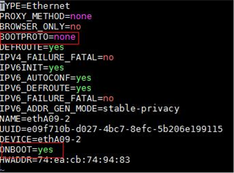
2. Open and edit the configuration file of the network interface. In this example, the configuration file of network interface ens34 is edited.
[root@node1 /]# vi /etc/sysconfig/network-scripts/ifcfg-ens34
3. Set the BOOTPROTO field to none to not specify a boot-up protocol and set the ONBOOT field to yes to activate the network interface at system startup.
Figure 4 Modifying the configuration file for a network interface
4. Execute the ifdown and ifup commands in sequence to reboot the network interface.
[root@node1 /]# ifdown ens34
[root@node1 /]# ifup ens34
5. Execute the ifconfig command to verify that the network interface is in up state.
Plan the networks
Network planning
Standalone deployment of the simulation device host
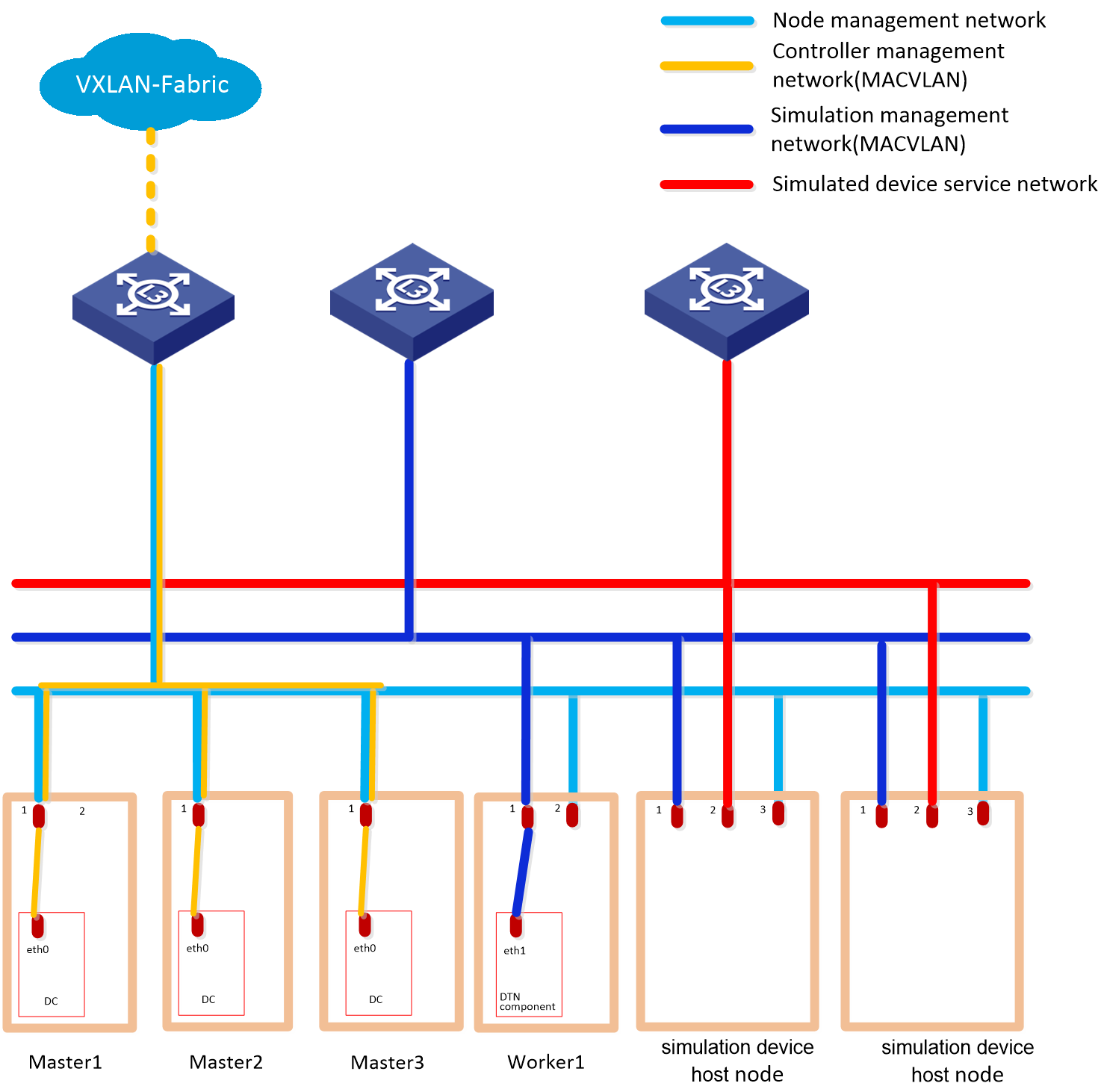
A simulation network includes four types of networks, including node management network, controller management network, simulation management network, and simulated device service network.
· Node management network—Network over which you can log in to servers to perform routine maintenance.
· Controller management network—Network for cluster communication between controllers and device management.
· Simulation management network—Network over which the digital twin network (DTN) microservice component and simulation device hosts exchange management information.
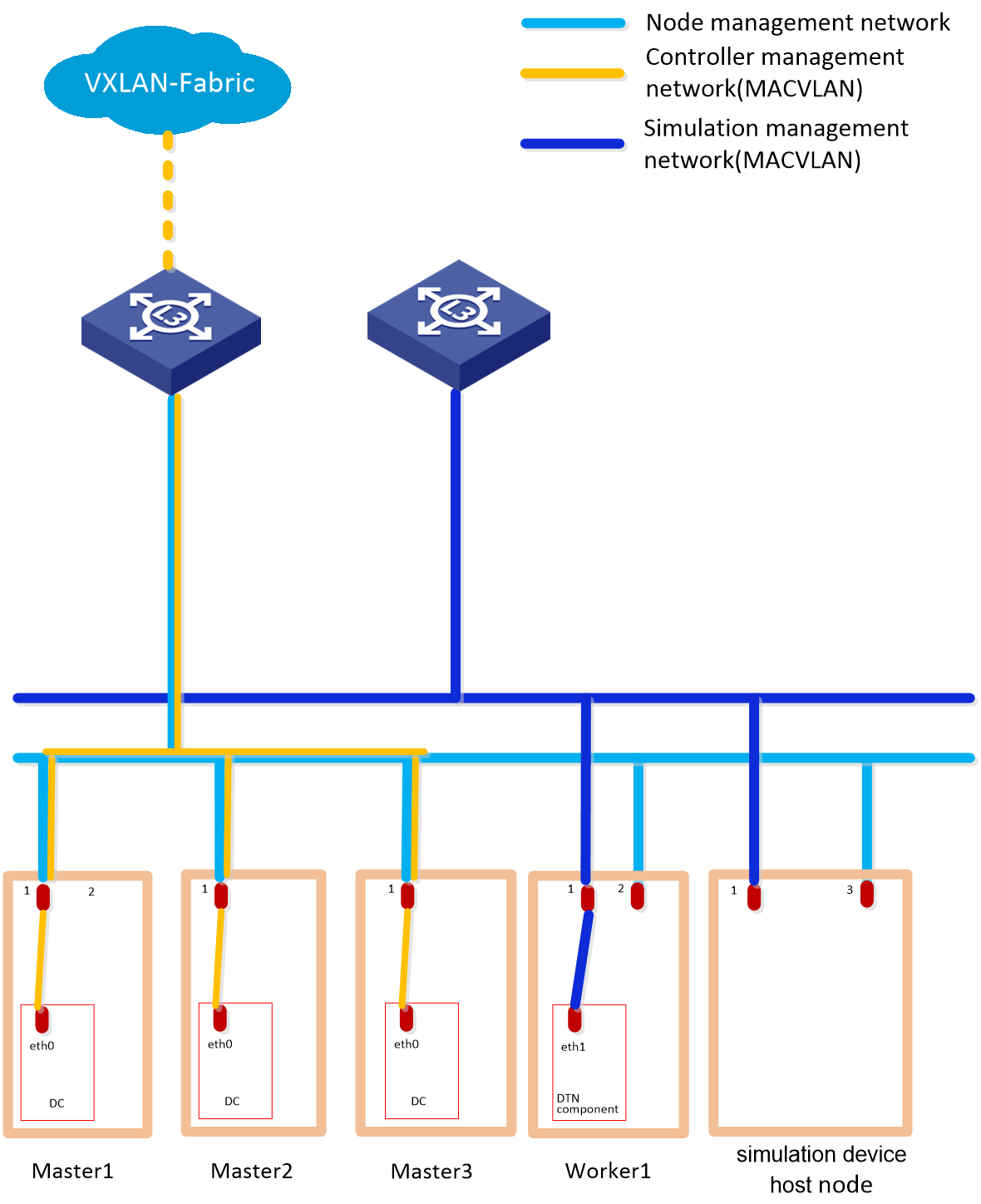
· Simulated device service network—Network over which the simulation device hosts exchange service data. When multiple simulation device hosts exist, they must communicate with each other through a switch, as shown in Figure 5. If only one simulation device host exists, a connection between the simulation device host and the switch is not needed, as shown in Figure 6.
Before you deploy the simulation system, plan the simulation management network and simulated device service network.
|
|
CAUTION: · If the controller management network and simulation management network use the same management switch, you must also configure VPN instances for isolation on the management switch to prevent IP address conflicts from affecting the services. If the controller management network and simulation management network use different management switches, physically isolate these switches. For the Layer 3 network configuration, see "Deploy ." · Configure routes to provide Layer 3 connectivity between simulation management IPs and simulated device management IPs. · On the port connecting the switch to the service interface of a simulation device host, execute the port link-type trunk command to configure the link type of the port as trunk, and execute the port trunk permit vlan vlan-id-list command to assign the port to 150 contiguous VLAN IDs. Among these VLAN IDs, the start ID is the VLAN ID specified when installing the simulation device host, and the end VLAN ID is the start VLAN ID+149. For example, if the start VLAN ID is 11, the permitted VLAN ID range is 11 to 160. When you plan the network, do not use any VLAN ID permitted by the port. · When the device and controllers are deployed across Layer 3 networks, the simulation device hosts and DTN component must be connected through the management switch. |
Convergence deployment of the simulation device host
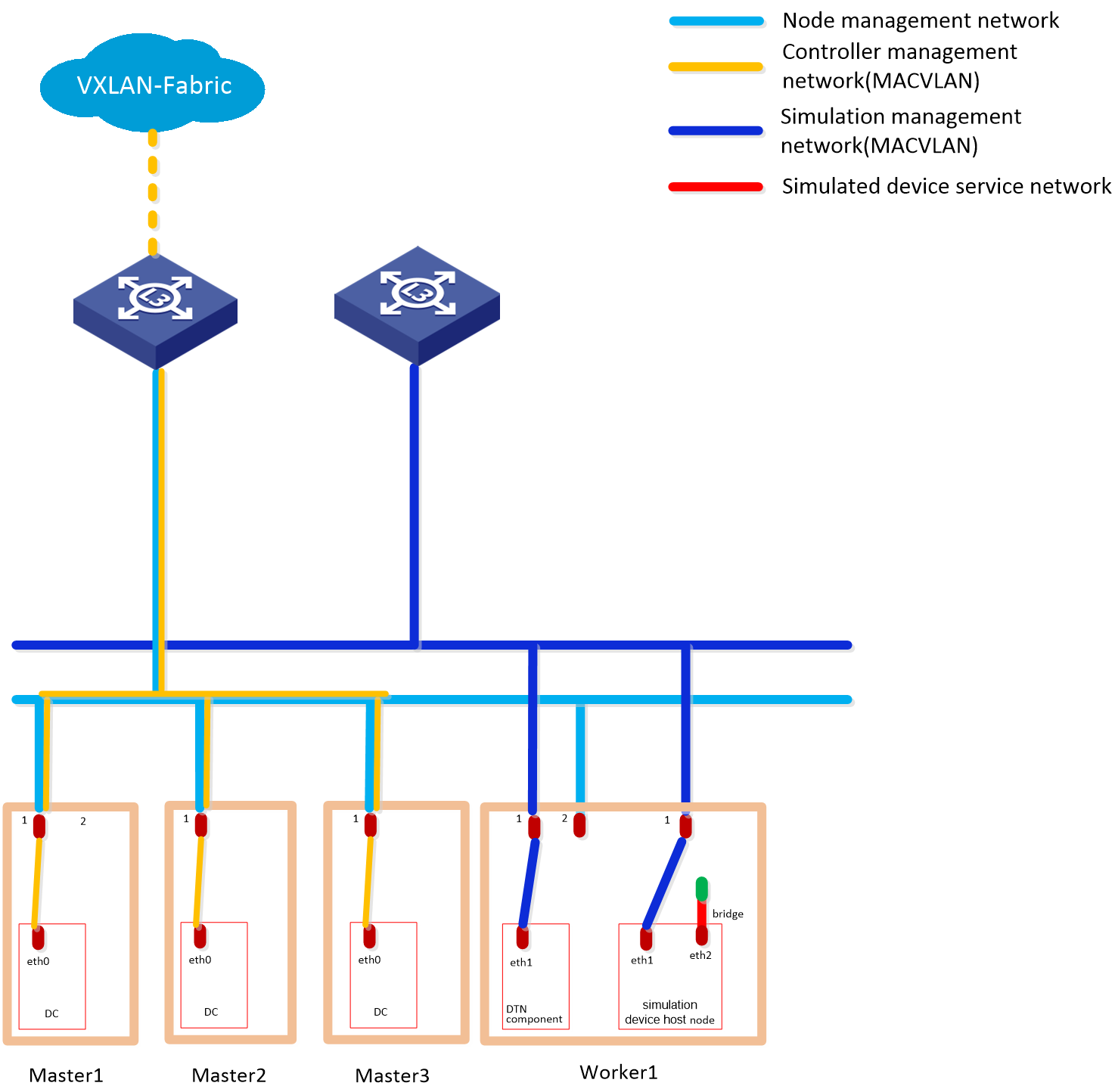
A simulation network includes four types of networks, including node management network, controller management network, simulation management network, and simulated device service network.
· Node management network—Network over which you can log in to servers to perform routine maintenance.
· Controller management network—Network for cluster communication between controllers and device management.
· Simulation management network—Network over which the other components and simulation device hosts exchange management information.
· Simulated device service network—Network connected to the default bridge virbr0 of libvirt. The bridge is not bound to a physical NIC. In the current software version, only one lite host is supported.
Figure 7 Typical simulation network topology design for the Cloud DC scenario in non-remote disaster recovery mode (with virtualization simulation device host)
Plan the IP address assignment scheme
Standalone deployment of the simulation device host
As a best practice, calculate the number of IP addresses on each network as shown in Table 11.
Table 11 Number of addresses in subnet IP address pools
|
Component/Node name |
Network name (type) |
Max number of cluster members |
Default number of cluster members |
Calculation method |
Remarks |
|
SeerEngine-DC |
Controller management network (MACVLAN) |
32 |
3 |
1 × cluster member count + 1 (cluster IP) |
N/A |
|
DTN component |
Simulation management network (MACVLAN) |
1 |
1 |
Single node deployment, which requires only one IP. |
Used by the simulation microservice deployed on the controller node |
|
Simulation device hosts |
Simulation management network |
Number of simulation device hosts |
Number of simulation device hosts |
Number of simulation device hosts |
Used by the DTN microservice component to incorporate simulation device hosts |
|
Simulated device service network |
Number of simulation device hosts |
Number of simulation device hosts |
Number of simulation device hosts |
IPv4 addresses used for service communication between simulated devices. Configure these addresses in "Configure the simulation device hosts." |
|
|
Node management network |
Number of simulation device hosts |
Number of simulation device hosts |
Number of simulation device hosts |
Use for logging in to the host remotely for routine maintenance |
Table 12 IP address plan example
|
Component/node name |
Network name (type) |
IP address |
|
SeerEngine-DC |
Controller management network (MACVLAN) |
Subnet: 192.168.12.0/24 (gateway address: 192.168.12.1) |
|
Network address pool: 192.168.12.101/24 to 192.168.12.132/24 (gateway address: 192.168.12.1) |
||
|
DTN component |
Simulation management network (MACVLAN) |
Subnet: 192.168.15.0/24 (gateway address: 192.168.15.1) |
|
Network address pool: 192.168.15.133/24 to 192.168.15.133/24 (gateway address: 192.168.15.1) |
||
|
Simulation device hosts |
Simulation management network |
Network address pool: 192.168.12.134/24 to 192.168.12.144/24 (gateway address: 192.168.12.1) |
|
Simulated device service network |
Network address pool: 192.168.11.134/24 to 192.168.11.144/24 (gateway address: 192.168.11.1) |
|
|
Node management network |
Network address pool: 192.168.10.110/24 to 192.168.10.120/24 (gateway address: 192.168.10.1) |
|
|
IMPORTANT: The node management network, simulation management network, and simulated device service network of a simulation device host must be on different network segments. |
Convergence deployment of the simulation device host
As a best practice, calculate the number of IP addresses on each network as shown in Table 13.
Table 13 Number of addresses in subnet IP address pools
|
Component/node name |
Network name (type) |
Max members in cluster |
Default members in cluster |
Calculation method |
Remarks |
|
SeerEngine-DC |
Controller management network (MAC-VLAN) |
32 |
3 |
1×Cluster member count+1 (cluster IP) |
N/A |
|
DTN component |
Simulation management network (MAC-VLAN) |
1 |
1 |
Single node deployment, which needs only one IP |
Used by the simulation microservice deployed on the controller node |
|
Virtualization simulation device host node |
Simulation management network |
1 |
1 |
Single node deployment, which needs only one IP |
Used by the simulation microservice to incorporate hosts |
Table 14 IP address planning
|
Component/node name |
Network name (type) |
IP address |
|
SeerEngine-DC |
Controller management network (MAC-VLAN) |
Subnet: 192.168.12.0/24 (gateway address: 192.168.12.1) |
|
Network address pool: 192.168.12.101/24 to 192.168.12.132/24 (gateway address: 192.168.12.1) |
||
|
DTN component |
Simulation management network (MAC-VLAN) |
Subnet: 192.168.15.0/24 (gateway address: 192.168.15.1) |
|
Network address pool: 192.168.15.133/24 to 192.168.15.133/24 (gateway address: 192.168.15.1). |
||
|
Virtualization simulation device host node |
Simulation management network |
Network address pool: 192.168.12.134/24 to 192.168.12.144/24 (gateway address: 192.168.12.1) |
Deploy DTN component
Before deploying the DTN component on Unified Platform, first deploy the SeerEngine-DC installation packages and Unified Platform application packages on Unified Platform.
1. Install Unified Platform.
For the Unified Platform installation procedure, see H3C Unified Platform Deployment Guide.
You can manually deploy optional application packages on the Matrix page. You can choose to deploy optional packages after deploying the controller or before deploying the controller. Make sure the optional application package version matches the required package version to avoid deployment failure.
2. Enter the address for accessing Unified Platform in the address bar and then press Enter.
By default, the login address is http://ip_address:30000/central/index.html.
¡ ip_address represents the cluster northbound virtual IP address of Unified Platform.
¡ 30000 is the port number.
3. Click System > Deployment.
4. Obtain the SeerEngine-DC installation packages and DTN installation package. Table 15 provides the names of the installation packages. Make sure you select installation packages specific to your server type, x86 or ARM.
Table 15 Installation packages
|
Component |
Installation package name |
Remarks |
|
SeerEngine-DC |
· x86: SeerEngine_DC-version-MATRIX.zip · ARM: SeerEngine_DC-version-ARM64.zip |
Required |
|
DTN |
· x86: SeerEngine_DC_DTN-version.zip · ARM: SeerEngine_DC_DTN-version-ARM64.zip |
Optional, for providing simulation services |
|
|
IMPORTANT: · The DTN version must be consistent with the SeerEngine-DC version. |
5. Click Upload , click Select File in the dialog box that opens, select an installation package, and then click Upload to upload the installation package. After the upload finishes, click Next.
Figure 8 Uploading an installation package

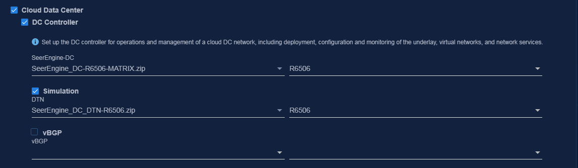
6. Select Cloud Data Center, then select DC Controller and Simulation. Then click Next.
Figure 9 Selecting components
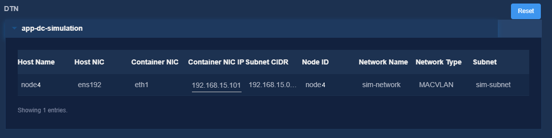
7. Configure the MACVLAN networks and add the uplink interfaces according to the network plan in "Plan the networks."
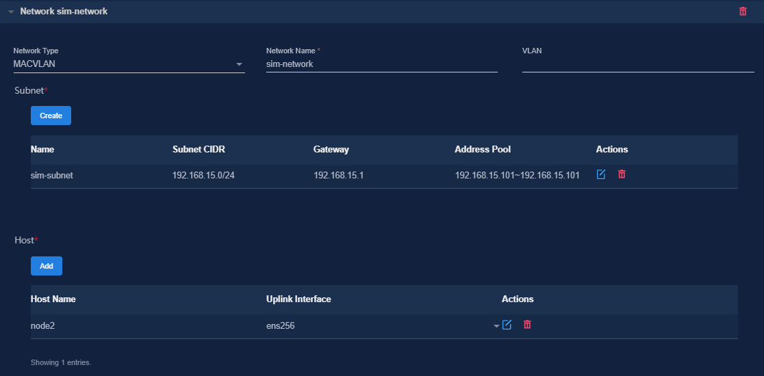
To use simulation services, configure a separate MACVLAN network for the DTN component. Be sure that the subnet IP address pool for the network contains a minimum of one IP address.
Figure 10 Configuring a MACVLAN management network for the SeerEngine-DC component
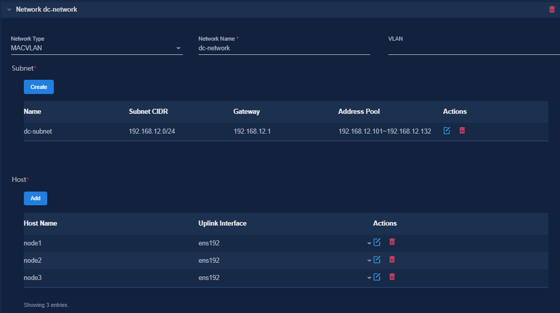
Figure 11 Configuring a MACVLAN management network for the DTN component
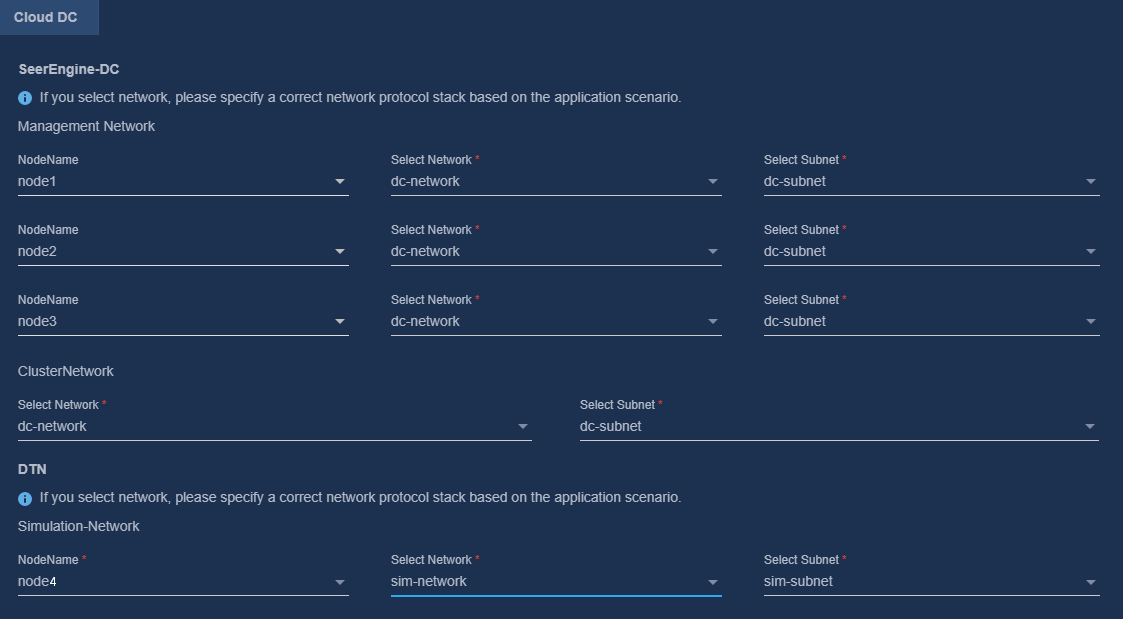
8. Bind networks to the components, assign IP address to the components, specify a network node for the service simulation network, and then click Next.
Figure 12 Binding networks (cloud DC)
9. On the Confirm Parameters tab, verify network information.
A component automatically obtains an IP address from the IP address pool of the subnet bound to it. To modify the IP address, click Modify and then specify another IP address for the component. The IP address specified must be in the IP address range of the subnet bound to the component.
Figure 13 Confirming parameters (SeerEngine-DC)
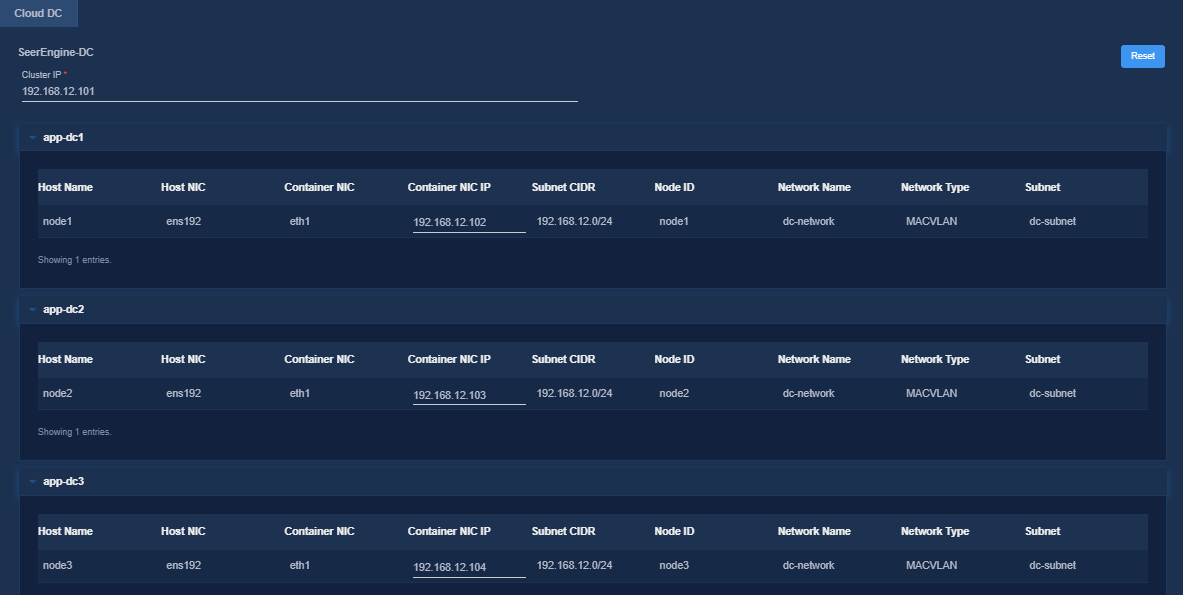
Figure 14 Confirming parameters (DTN)
10. Click Deploy.
Deploy the simulation device host in standalone mode
Install the operating system
|
|
NOTE: · The simulation device host depends on the virtualization capability of the system. When selecting the software options, select the virtualization capability. · As a best practice to enhance system stability, use the recommended device type and file system type for partitioning. · The simulation device host can be deployed on a virtualization platform. · Before deploying the simulation device host on the virtualization platform, enable nested virtualization. For more information, see "When I deploy a simulation device host on a VMware ESXI VM, how can I enable the nested virtualization feature for VMware and the simulation device host?" and "When I deploy a simulation device host on a CAS VM, how can I enable the nested virtualization feature for CAS and the simulation device host?" · Installing the H3Linux operating system on a server that already has an operating system installed replaces the existing operating system. To avoid data loss, back up data before you install the H3Linux operating system. |
H3Linux operating system
|
|
CAUTION: Before you install H3Linux on a server, back up server data. H3Linux will replace the original OS (if any) on the server with data removed. |
H3Linux-version-platform.iso is the H3Linux operating system installation image. The version parameter represents the software version number, and the platform parameter represents the software architecture. The following information uses a server without an OS installed for example to describe the installation procedure of the H3Linux-2.0.2-SP01-x86_64-dvd.iso image. The installation procedures for H3Linux-2.0.2-SP01-aarch64-dvd.iso are the same. This section uses the x86_64 architecture as an example.
1. Obtain the required H3Linux-2.0.2-SP01-x86_64-dvd.iso image in ISO format.
2. Access the remote console of the server, and then mount the ISO image as a virtual optical drive.
3. Configure the server to boot from the virtual optical drive, and then restart the sever.
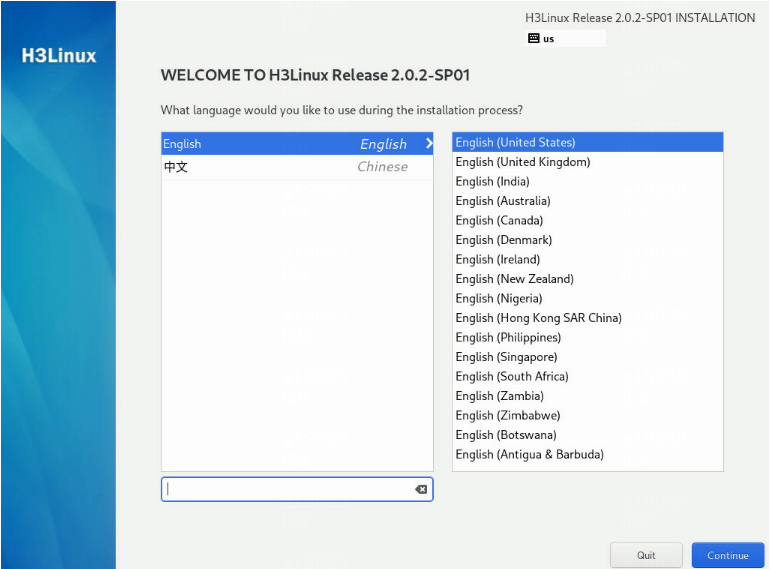
4. After loading is completed, access the page for selecting a language. In this example, select English. Click Continue.
Figure 15 Selecting the language
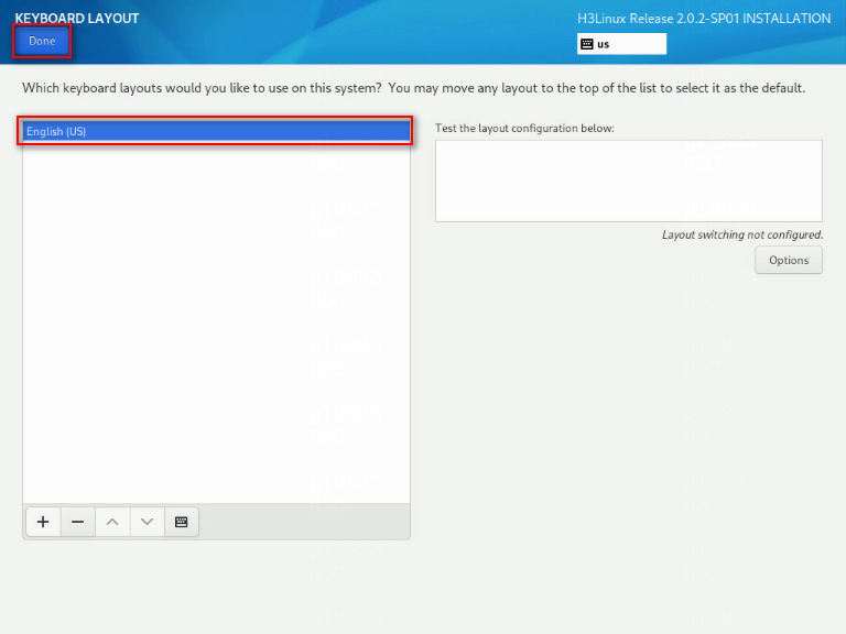
5. Click the KEYBOARD (K) link in the LOCALIZATION area to select the keyboard layouts. Click the + button to add a keyboard layout. After selecting the keyboard layout, click Done.
By default, only the English (United States) option is selected.
Figure 16 Localization - Keyboard
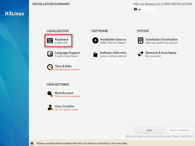
Figure 17 Adding the Chinese keyboard layout
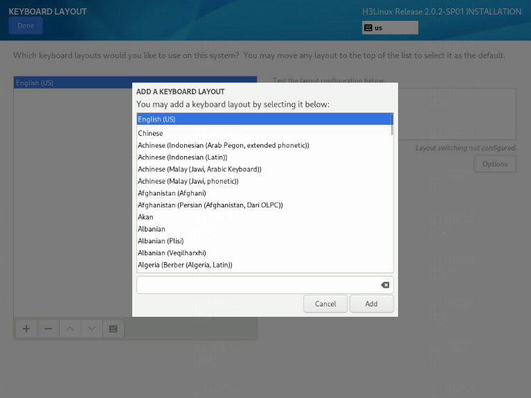
Figure 18 Selecting the Chinese keyboard layout
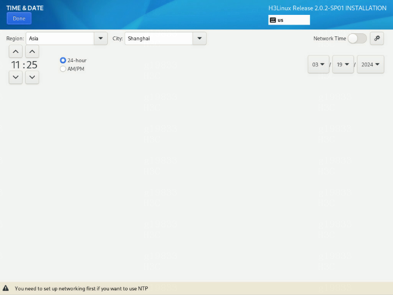
6. Click the DATE & TIME (T) link in the LOCALIZATION area to access the date & time selection page. In this example, select Asia/Shanghai/16:25. Click Done.
Figure 19 Selecting date & time (T)
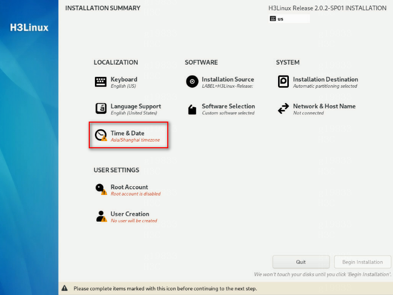
Figure 20 Selecting the Asia/Shanghai time zone
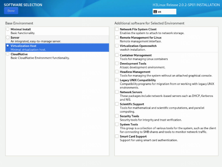
7. Click the SOFTWARE SELECTION (S) link in the SOFTWARE area and access the page for selecting software. Select the Virtualization Host option in the Base Environment area, and click Done to return to the installation summary page.
Figure 21 Software selection page
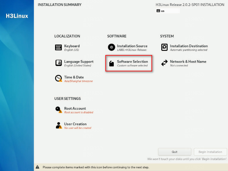
Figure 22 Selecting the virtualization host option in the base environment area
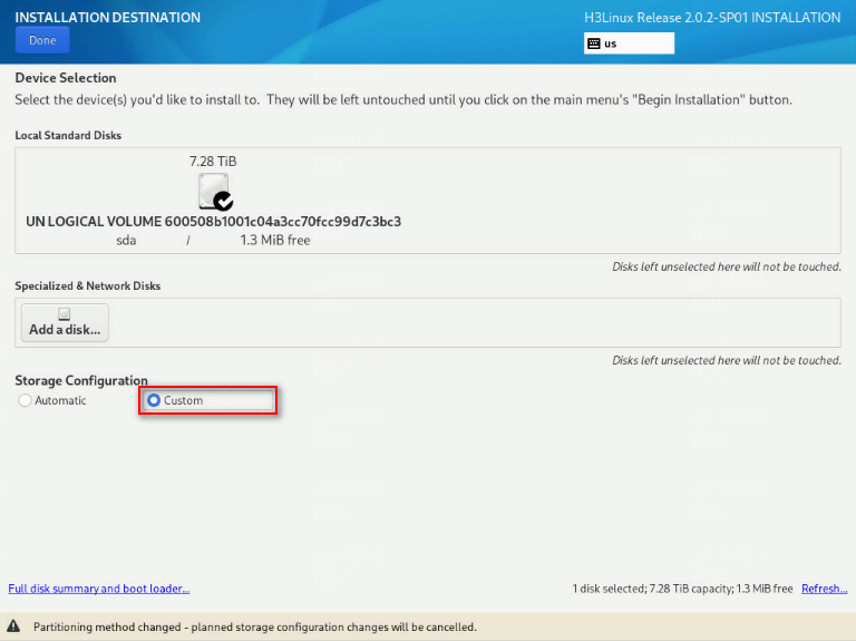
8. Click the INSTALLATION DESTINATION (D) link in the SYSTEM area to access the page for selecting the installation destination. In the Local Standard Disks area, select the target disk. In the Storage Configuration area, select the Custom option. Click Done to access the manual partitioning page.
Figure 23 INSTALLATION DESTINATION page
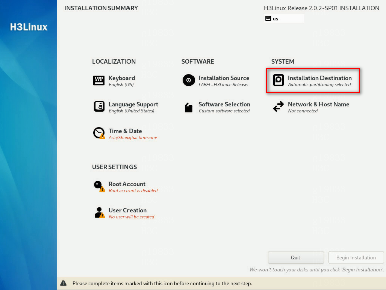
Figure 24 Selecting the Custom option
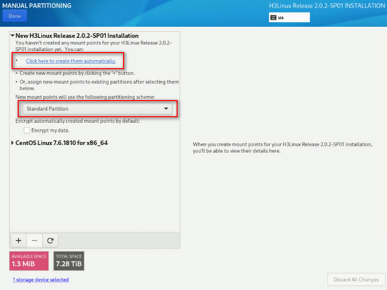
9. On the manual partitioning page, select the standard partitioning scheme. Click Click here to create them automatically (C) to automatically generate recommended partitions.
By default, the LVM partitioning scheme is selected.
Figure 25 MANUAL PARTITIONING page
The list of automatically created partitions opens. Figure 26 shows the list of automatically created partitions.
|
|
IMPORTANT: The /boot/efi partition is available only if UEFI mode is enabled for OS installation. |
Figure 26 Automatically created partition list
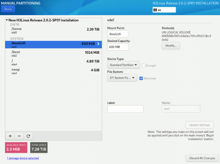
10. As a best practice to improve system stability, set the device type to Standard Partition.
Table 16 shows the device type and file system of each partition used in this document.
|
Partition name |
Device type |
File system |
|
/boot |
Standard partition |
xfs |
|
/boot/efi (UEFI mode) |
Standard partition |
EFI System Partition |
|
/ |
Standard partition |
xfs |
|
/swap |
Standard partition |
swap |
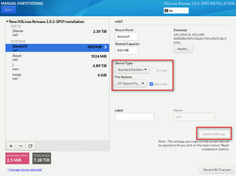
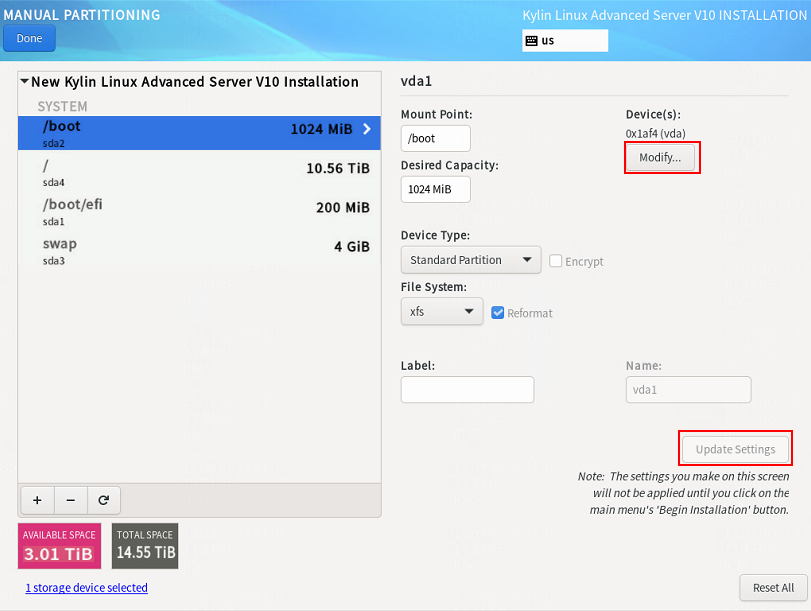
11. Edit the device type and file system of a partition. Take the /boot/efi partition as an example. Select a partition on the left, and select Standard Partition from the Device Type list and EFI System Partition from the File System list. Then, click Update Settings.
Figure 27 Editing the device type and file system
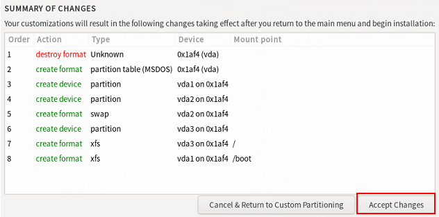
12. After you finish the partitioning task, click Done in the upper left corner. In the dialog box that opens, select Accept Changes.
Figure 28 Accepting changes

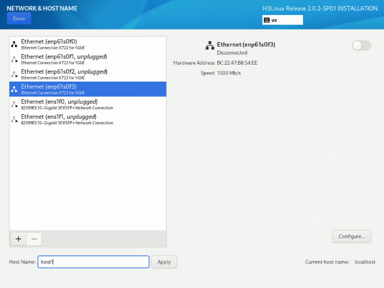
13. In the INSTALLATION SUMMARY window that opens, click NETWORK & HOSTNAME in the SYSTEM area to configure the host name and network settings.
14. In the Host name field, enter the host name (for example, host01) for this server, and then click Apply.
Figure 29 Setting the host name
15. Configure the network settings:
|
|
IMPORTANT: Configure network ports as planned. The server requires a minimum of three network ports. · The network port IP for the simulation management network is used for communication with the DTN component. · The network port IP for the simulated device service network is used for service communication between simulated devices. Specify this IP address in the installation script in “Configure the simulation device hosts”, and you do not need to specify this IP address in this section. · The network port IP for the node management network is used for routine maintenance of servers. |
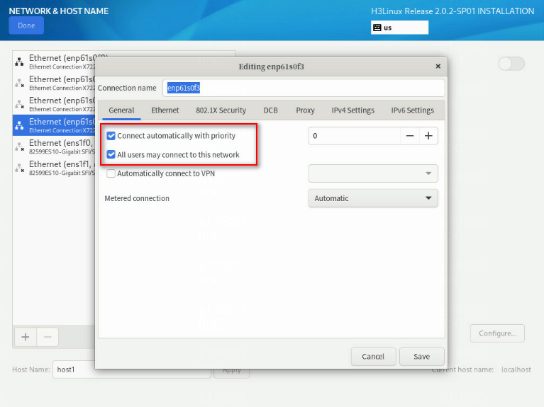
a. Select a network port and then click Configure.
b. In the dialog box that opens, configure basic network port settings on the General tab:
- Select the Automatically connect to this network when it is available option .
- Verify that the All users may connect to this network option is selected. By default, this option is selected.
Figure 30 General settings for a network port
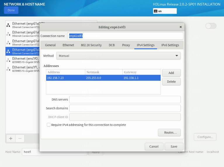
16. Configure IP address settings:
a. Click the IPv4 Settings or IPv6 Settings tab.
b. From the Method list, select Manual.
c. Click Add, assign a simulation management IP address to the simulation device host, and then click Save.
d. Click Done in the upper left corner of the dialog box.
|
|
IMPORTANT: DTN service supports IPv4 and IPv6. In the current software version, only a single stack is supported. |
Figure 31 Configuring IPv4 address settings for a network port
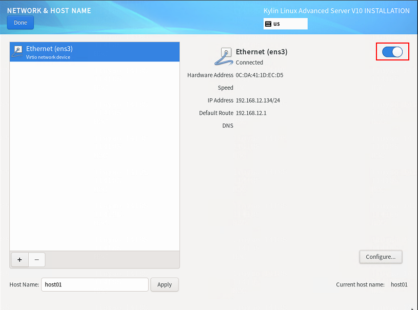
17. On the NETWORK & HOST NAME page, enable the specified Ethernet connection.
Figure 32 Enabling an Ethernet connection

18. Repeat steps 15 through 17 to configure the management IP addresses for other simulation device hosts.
The IP addresses must be in the network address pool containing IP addresses 192.168.10.110 to 192.168.10.120, for example, 192.168.10.110.
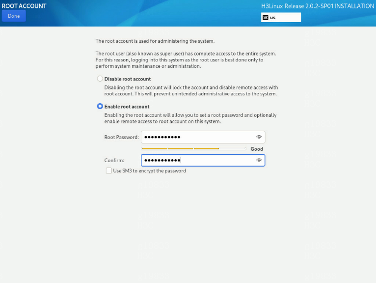
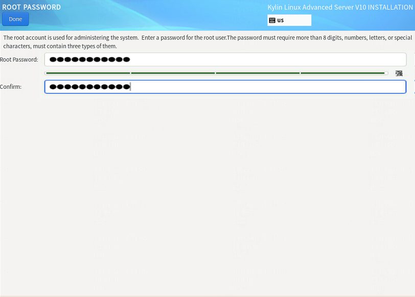
19. In the USER SETTINGS area, click the ROOT ACCOUNT link if you use the root user as the administrator. On the ROOT ACCOUNT page, enable the root account and configure the root password. If you use the Admin user as the administrator, you can click the USER CREATION (U) link to configure the relevant information for the admin user.
Figure 33 Setting the root account
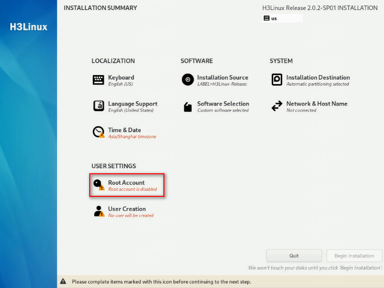
Figure 34 Configuring the root password
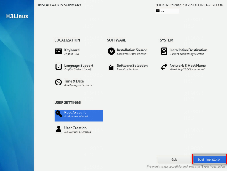
20. After completing the above configuration, click Begin Installation.
Figure 35 Clicking the Begin Installation button
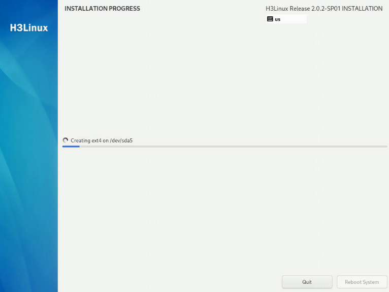
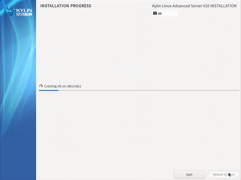
21. After the installation is complete, click Reboot System.
Figure 36 Operating system installation in progress
Kylin V10SP02 operating system
Installing the Kylin V10SP02 operating system
|
|
IMPORTANT: Before you install the Kylin V10SP02 operating system on a server, back up server data. Kylin will replace the original OS (if any) on the server with data removed. |
The Kylin operating system installation package is named in the Kylin-Server-version.iso (where version is the version number) format. The following information uses a server without an OS installed as an example to describe the installation procedure for the Kylin V10SP02 operating system.
1. Obtain the required version of the Kylin-Server-version.iso image.
2. Access the remote console of the server, and then mount the ISO image on a virtual optical drive.
3. Configure the server to boot from the virtual optical drive, and then restart the sever.
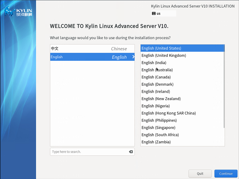
4. After the ISO image is loaded, select a language used during the installation process.
English is selected in this example.
Figure 37 Selecting a language used during the installation process
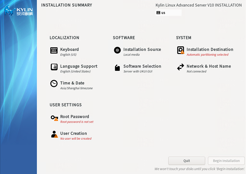
5. The INSTALLATION SUMMARY page opens.
Figure 38 INSTALLATION SUMMARY page
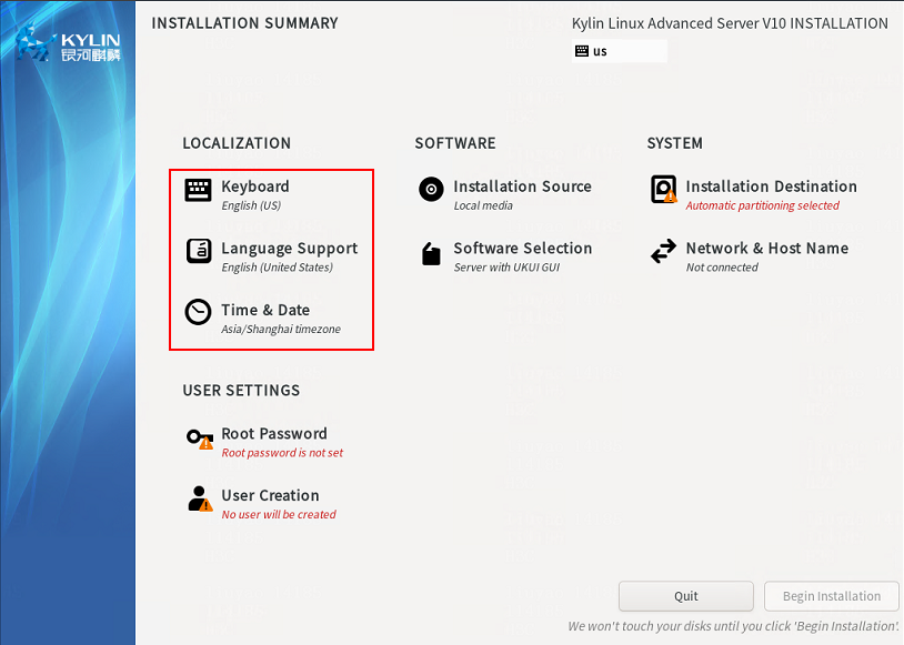
6. In the LOCALIZATION area, perform the following tasks:
¡ Click KEYBOARD to select the keyboard layout.
¡ Click LANGUAGE SUPPORT to select your preferred language.
¡ Click TIME & DATE to set the system date and time. Make sure you configure the same time zone for all hosts. The Asia/Shanghai timezone is specified in this example.
Figure 39 INSTALLATION SUMMARY page
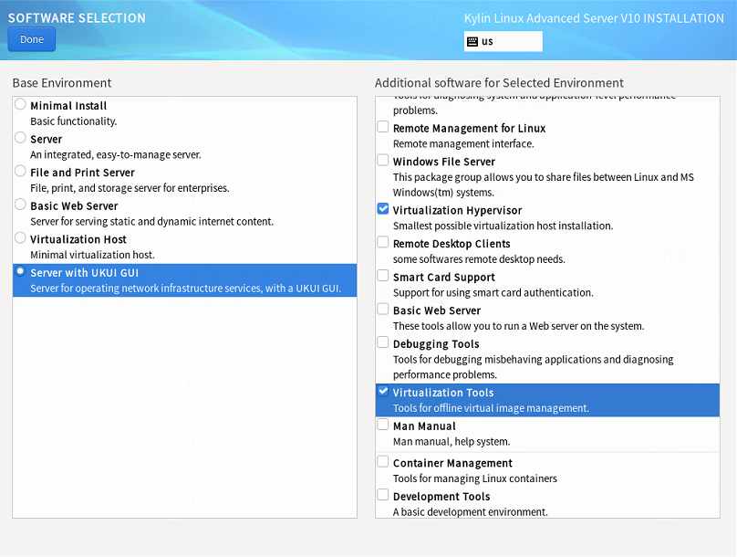
7. Click SOFTWARE SELECTION in the SOFTWARE area to enter the page for selecting software. Select the Server with UKUI GUI base environment and the File and Storage Server, Virtualization Hypervisor, and Virtualization Tools additional software for the selected environment. Then, click Done to return to the INSTALLATION SUMMARY page.
Figure 40 Selecting software (1)

Figure 41 Selecting software (2)
8. In the SYSTEM area, click INSTALLATION DESTINATION.
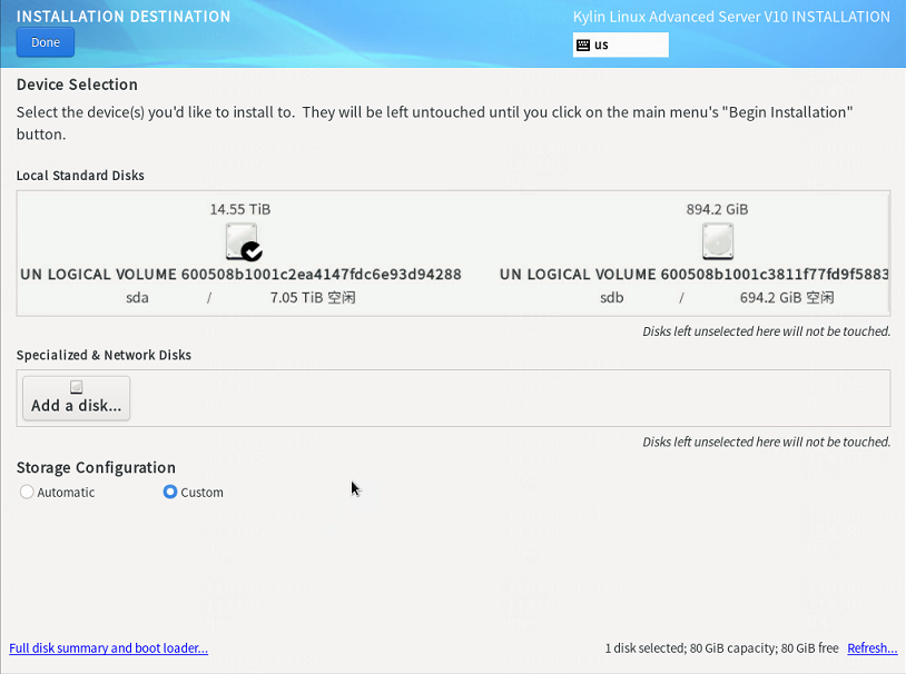
9. On the INSTALLATION DESTINATION page, perform the following tasks:
a. Select the target disk from the Local Standard Disks area.
b. Select Custom in the Storage Configuration area.
c. Click Done.
Figure 42 INSTALLATION DESTINATION page
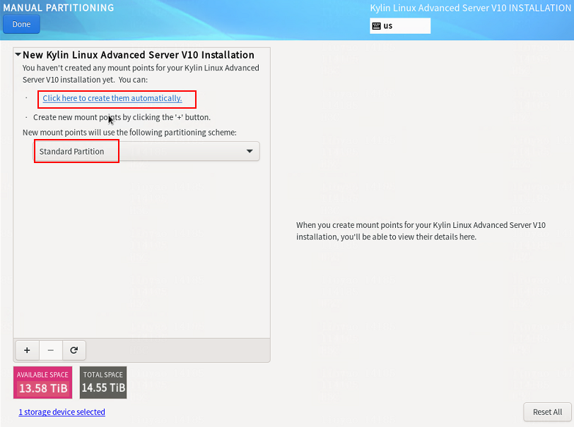
10. On the MANUAL PARTITIONING page, select the Standard Partition partitioning scheme and then click Click here to create them automatically to automatically generate recommended partitions.
Figure 43 MANUAL PARTITIONING page
11. The list of automatically created partitions is displayed.
The /boot/efi partition is available only if UEFI mode is enabled for OS installation. If this partition does not exist, add it manually.
Figure 44 Automatically created partition list
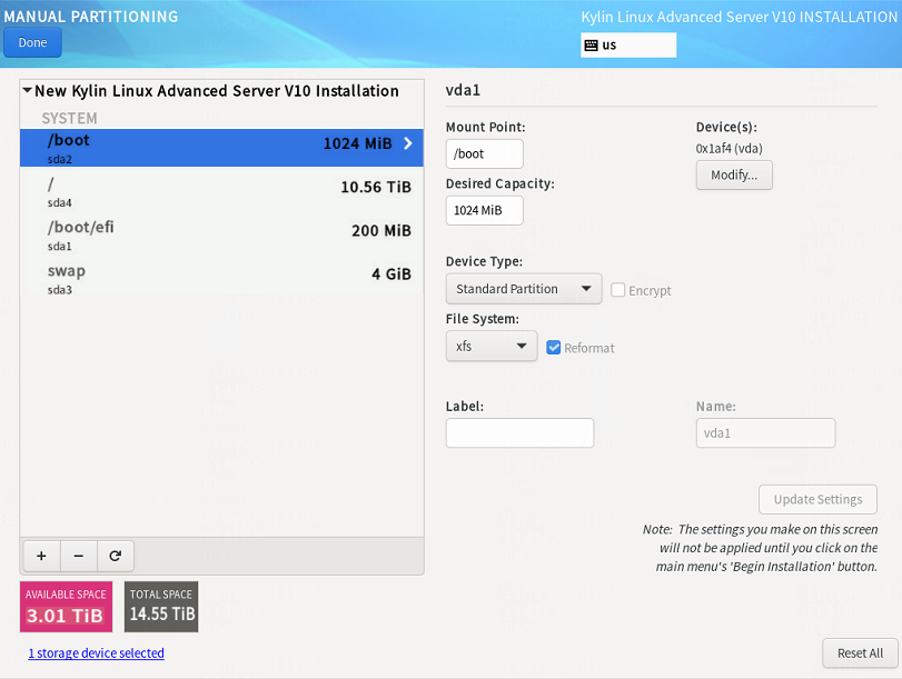
12. Set the device type and file system for each partition. As a best practice, set the device type to Standard Partition to improve system stability. Table 17 shows the device type and file system of each partition used in this document.
|
Partition name |
Device type |
File system |
|
/boot |
Standard Partition |
xfs |
|
/boot/efi (UEFI mode) |
Standard Partition |
EFI System Partition |
|
/ |
Standard Partition |
xfs |
|
/swap |
Standard Partition |
swap |
13. Edit the device type and file system of a partition as shown in Figure 45. Take the /boot partition for example. Select a partition on the left, and select Standard Partition from the Device Type list and xfs from the File System list. Then, click Update Settings.
Figure 45 Configuring partitions
14. After you finish the partitioning task, click Done in the upper left corner. In the dialog box that opens, select Accept Changes.
Figure 46 Accepting changes
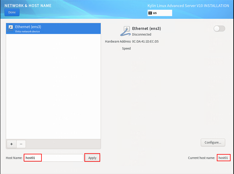
15. In the INSTALLATION SUMMARY window that opens, click NETWORK & HOSTNAME in the SYSTEM area to configure the host name and network settings.
16. In the Host name field, enter the host name (for example, host01) for this server, and then click Apply.
Figure 47 Setting the host name
17. Configure the network settings:
|
|
IMPORTANT: Configure network ports as planned. The server requires a minimum of three network ports. · The network port IP for the simulation management network is used for communication with the DTN component. · The network port IP for the simulated device service network is used for service communication between simulated devices. Specify this IP address in the installation script in “Configure the simulation device hosts”, and you do not need to specify this IP address in this section. · The network port IP for the node management network is used for routine maintenance of servers. |
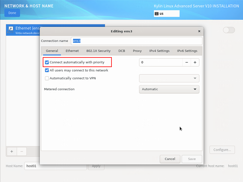
a. Select a network port and then click Configure.
b. In the dialog box that opens, configure basic network port settings on the General tab:
- Select the Connect automatically with priority option.
- Verify that the All users may connect to this network option is selected. By default, this option is selected.
Figure 48 General settings for a network port
18. Configure IP address settings:
a. Click the IPv4 Settings or IPv6 Settings tab.
b. From the Method list, select Manual.
c. Click Add, assign a simulation management IP address to the simulation device host, and then click Save.
d. Click Done in the upper left corner of the dialog box.
|
|
IMPORTANT: DTN service supports IPv4 and IPv6. In the current software version, only a single stack is supported. |
Figure 49 Configuring IPv4 address settings for a network port
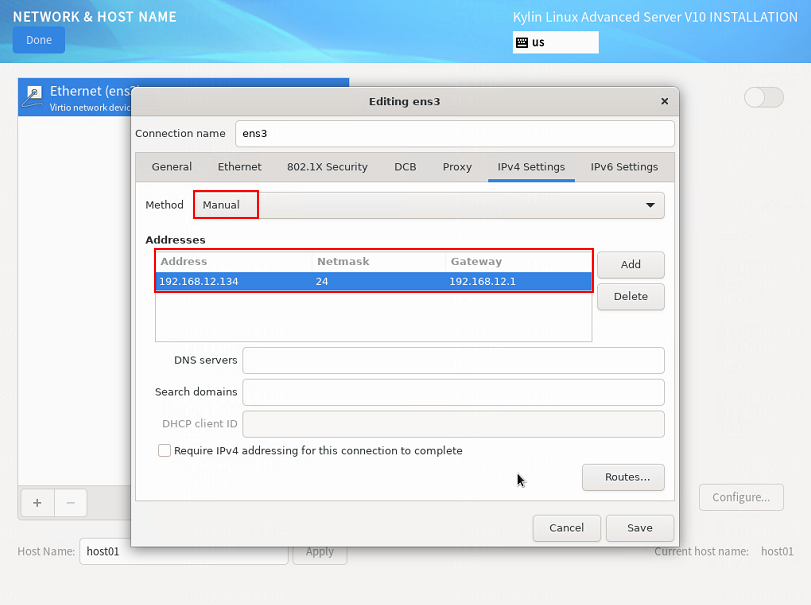
Figure 50 Enabling Ethernet connection
19. Repeat step 17 and step 18 to configure the management IP addresses for other simulation device hosts. The IP addresses must be in the network address pool containing IP addresses 192.168.10.110 to 192.168.10.120, for example, 192.168.10.110.
20. On the INSTALLATION SUMMARY page, click Root Password in the USER SETTINGS area. In the dialog box that opens, set the root password for the system, and then click Done in the upper left corner.
Figure 51 Setting the root password
21. Click Begin Installation to install the OS. After the installation is complete, click Reboot System in the lower right corner.
Figure 52 Installation in progress
Disabling the auditd service
The auditd service might be memory intensive. If you are not to use the auditd service on the Kylin V10SP02 operating system, disable the auditd service.
To disable the auditd service:
1. Stop the auditd service.
[root@uc log]# systemctl stop auditd
2. Disable the auditd service.
[root@uc log]# systemctl disable auditd
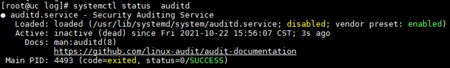
3. Confirm the state of the auditd service.
[root@uc log]# systemctl status auditd
Figure 53 Disabling the auditd service
Installing the dependency package
For the simulation network to run correctly on the Kylin hosts, upgrade the libndp dependency package that comes with the system. The following section uses an x86 software package as an example to describe the dependency package upgrade procedure.
To upgrade the libndp dependency package for the Kylin system:
1. Install the dependency package.
[root@localhost ~]# rpm -ivh --force libndp-1.7-6.el8.x86_64.rpm
Verifying... ################################# [100%]
Preparing for installation... ################################# [100%]
Upgrading/Installing...
1:libndp-1.7-6.el8 ################################# [100%]
2. View the libndp dependency packages in the system.
In this example, libndp-1.7-3.ky10.x86_64 is the dependency package that came with the system and libndp-1.7-6.el8.x86_64 is the newly installed package.
[root@localhost ~]# rpm -qa | grep ndp
libndp-1.7-3.ky10.x86_64
libndp-1.7-6.el8.x86_64
3. Uninstall the libndp dependency package that came with the system.
[root@localhost ~]# rpm -e libndp-1.7-3.ky10.x86_64
4. (Optional.) Execute the ndptool –help command to view whether the following fields are displayed in the command output.
[root@localhost ~]# ndptool --help
ndptool [options] command
-h --help Show this help
-v --verbose Increase output verbosity
-t --msg-type=TYPE Specify message type
("rs", "ra", "ns", "na")
-D --dest=DEST Dest address in IPv6 header for NS or NA
-T --target=TARGET Target address in ICMPv6 header for NS or NA
-i --ifname=IFNAME Specify interface name
-U --unsolicited Send Unsolicited NA
Available commands:
monitor
send
Configure the simulation device hosts
|
|
CAUTION: · Execution of the simulation device host installation script will cause the network service to restart and the SSH connection to disconnect. To avoid this situation, configure the simulation device host from the remote console of the server or VM. · You must configure each simulation device host as follows. · If you log in as a non-root user or the root user is disabled, add sudo before each command to be executed. |
1. Obtain the simulation device host installation package, upload it to the server, and then decompress it. The installation package is named in the SeerEngine_DC_DTN_HOST-version.zip format.
[root@host01 root]# unzip SeerEngine_DC_DTN_HOST-E6205.zip
2. Execute the chmod command to assign permissions to the user.
[root@host01 root]# chmod +x -R SeerEngine_DC_DTN_HOST-E6205
3. Access the SeerEngine_DC_DTN_HOST-version/ directory of the decompressed installation package, and execute the ./install.sh management_nic service_nic vlan_start service_cidr command to install the package.
Parameters:
management_nic: Simulation management network interface name.
service_nic: Simulation service network interface name.
vlan_start: Start VLAN ID.
service_cidr: CIDR for service communication among simulated devices.
[root@host01 SeerEngine_DC_DTN_HOST-E6205]# ./install.sh ens1f0 ens1f1 11 192.168.11.134/24
Installing ...cd
check network service ok.
check libvirtd service ok.
check management bridge ok.
check sendip ok.
check vlan interface ok.
Complete!
|
|
IMPORTANT: · VLANs are used for service isolation and is in the range of vlan_start to vlan_start+149 · During script execution, if the system prompts the "NIC {service_NIC_name} does not support 150 VLAN subinterfaces. Please select another service NIC for simulation." message, it means the selected NIC does not support configuring 150 VLAN subinterfaces. In this case, select another service NIC for simulation. · By default, the network service restart timeout timer is 5 minutes. After the simulation device host is deployed, the system will automatically modify the network service restart timeout timer to 15 minutes. |
Deploy the simulation device host in convergence mode
Restrictions and guidelines
· The virtualization simulation device hosts cannot be used together with simulation device hosts deployed on physical servers.
· Virtualization simulation device hosts only support single node deployment.
Install dependencies
1. Obtain the software package, and copy the software package to the destination directory on the server, or upload the software image to the specified directory through FTP.
|
|
NOTE: · Use the binary transfer mode to prevent the software package from being corrupted during transit by FTP or TFTP. · Install the dependency packages on the node selected for deploying the virtualization simulation device host. |
2. Log in to the back end of the Matrix node and use the following command to decompress the required dependency packages for the virtualization simulation device host.
[root@uc root]# unzip libvirt-dtnhost-E6501.zip
3. Execute the chmod command to assign permissions to users.
[root@uc root]# chmod +x -R libvirt-dtnhost-E6501
4. Access the directory of the decompressed dependency package and execute the installation command.
[root@uc root]# cd libvirt-dtnhost-E6501
[root@uc libvirt-dtnhost-E6501]# ./install.sh
5. Execute the virsh version command to identify whether libvirt has been installed.
If the libvirt version is displayed, it indicates libvirt is installed successfully.
Figure 54 libvirt image installed successfully

Deploy virtualization simulation device hosts
1. Enter the Matrix login address in your browser to access the Matrix login page.
¡ If an IPv4 address is used, the login address format is https://ip_address:8443/matrix/ui, for example, https://172.16.101.200:8443/matrix/ui. The following configurations in this document will be based on IPv4 configuration.
¡ If an IPv6 address is used, the login address format is https://[ip_address]:8443/matrix/ui, for example, https://[2000::100:611]:8443/matrix/ui.
The parameters in the login address are described as follows:
¡The ip_address parameter is the IP address of the node.
¡8443 is the default port number.
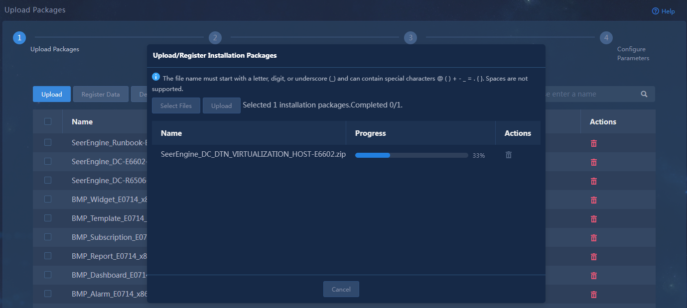
2. Access the Deploy > Convergence Deployment page, upload the installation package SeerEngine_DC_DTN_VIRTUALIZATION_HOST-version.zip, and click Next after the upload is completed.
Figure 55 Uploading the installation package
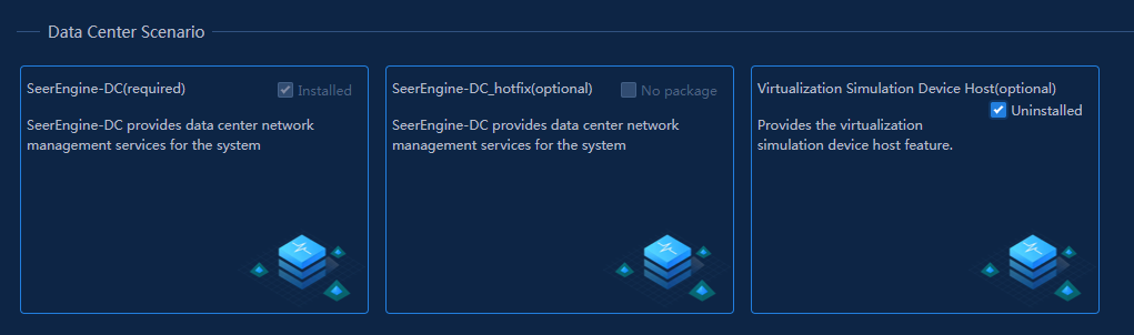
3. On the application selection page, select the Virtualization DTN Host (optional) option. Click Next.
Figure 56 Selecting applications
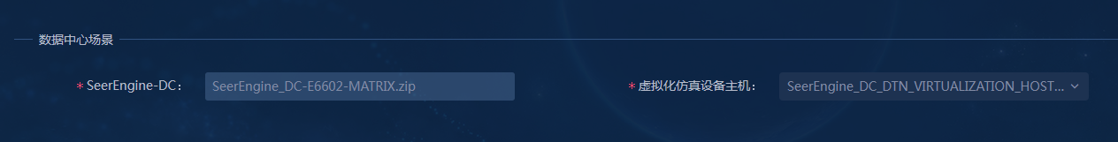
4. On the software installation package selection page, select the virtualization simulation device host component package to be deployed. Click Next.
Figure 57 Selecting installation packages
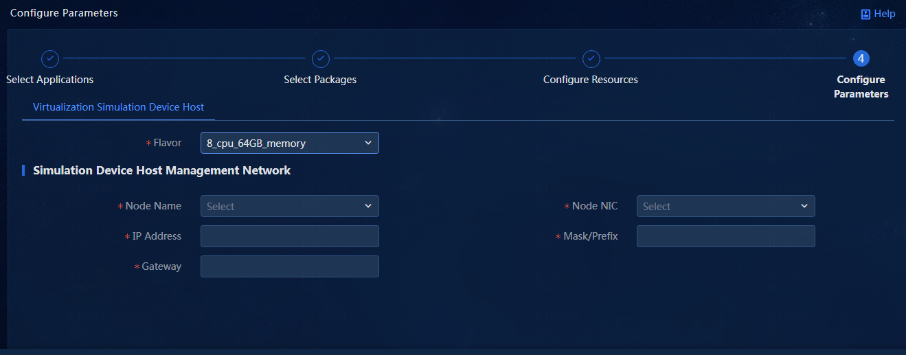
5. On the parameter configuration page, configure the necessary parameters for the virtualization simulation device host. Click Deploy.
Table 18 Virtualization simulation device host parameters
|
Parameter |
Description |
|
Flavor |
Possible values include: · 8_cpu_64GB_memory (default): Create a virtualization simulation device host with 8-core CPU and 64 GB memory. · 16_cpu_128GB_memory: Create a simulation device host with 16-core CPU and 128 GB memory. |
|
Node Name |
The specified node must be deployed through a physical server. |
|
Node NIC |
It must occupy a dedicated NIC. If the selected NIC conflicts with the one used by the DTN component, the virtualization simulation device host deployment will fail. |
|
IP Address |
IP address of the virtualization simulation device host. IPv4 and IPv6 addresses are supported. The IP address needs to communicate with the DTN component. |
|
Mask/Prefix |
Mask or prefix for the virtualization simulation device host. |
|
Gateway |
Gateway for the virtualization simulation device host. |
|
|
NOTE: · When the number of simulated devices (with the default specification of 1_cpu_2048MB_memory_2048MB_storage) is less than or equal to 30, as a best practice, select a virtualization simulation device host with the 8_cpu_64GB_memory specification. · When the number of simulated devices (with the default specification of 1_cpu_2048MB_memory_2048MB_storage) is greater than 30, as a best practice, select a virtualization simulation device host with the 16_cpu_128GB_memory specification. |
Figure 58 Configuration parameters
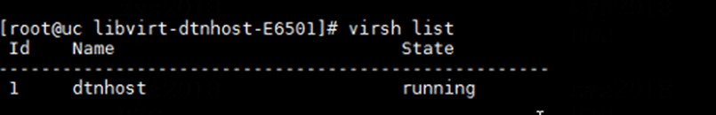
6. At the specified node, use the virsh list command to check the running status of the virtualization simulation device host.
If installation is successful, the State field will display running.
Figure 59 Successful installation of the VM corresponding to the virtualization simulation device host
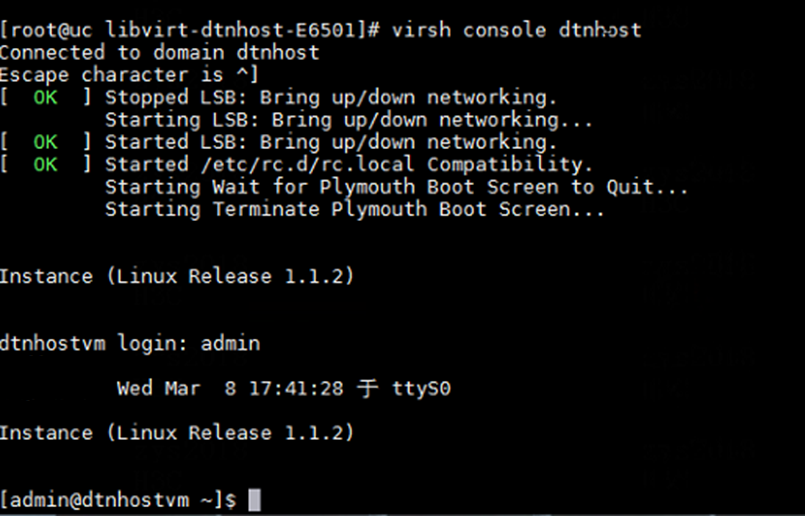
7. You can log in to the back end of the node where the virtualization simulation device host is deployed by using the virsh console dtnhost command.
The username of the virtualization simulation device host is admin by default, and the password is Pwd@12345 by default.
Figure 60 Logging in to the corresponding node of the virtualization simulation device host by using the virsh console dtnhost command
Deploy DTN over a Layer 3 network
Network configuration
In this example, the controller management network, node management network, simulation management network, and simulated device service network share one switch to deploy the Layer 3 management networks for simulation.
|
|
NOTE: This chapter describes the deployment of simulation device hosts on physical servers. The deployment method of virtualization simulation device hosts is the same as that of simulation device hosts. Select a deployment method as needed. |
Figure 61 Management network diagram
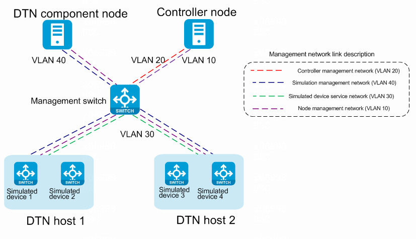
Table 19 IP planning for the simulation management network
|
Component/node name |
IP address plan |
Interfaces |
|
DTN component |
IP address: 192.168.15.133/24 (gateway address: 192.168.15.1) |
Ten-GigabitEthernet 1/0/25, VLAN 40 |
|
simulation device host 1 |
IP address: 192.168.12.134/24 (gateway address: 192.168.12.1, NIC: ens1f0) |
Ten-GigabitEthernet 1/0/26, VLAN 40 |
|
simulation device host 2 |
IP address: 192.168.12.135/24 (gateway address: 192.168.12.1, NIC: ens1f0) |
Ten-GigabitEthernet 1/0/27, VLAN 40 |
|
Simulated device 1 |
IP address: 192.168.11.136/24 (gateway address: 192.168.11.1) |
N/A |
|
Simulated device 2 |
IP address: 192.168.11.137/24 (gateway address: 192.168.11.1) |
N/A |
|
Simulated device 3 |
IP address: 192.168.21.134/24 (gateway address: 192.168.21.1) |
N/A |
|
Simulated device 4 |
IP address: 192.168.21.135/24 (gateway address: 192.168.21.1) |
N/A |
|
IPv4 management network address pool |
IP address: 2.0.0.0/22 (gateway address: 2.0.0.1) |
N/A |
|
|
NOTE: For a Layer 3 management network, use a management network address pool. (For an IPv6 management network, use an IPv6 management network address pool). To configure a management network address pool, follow these steps: · Log in to the controller. · Access the Automation > Data Center Networks > Simulation > Build Simulation Network page. · Click the Preconfigure button, and click the Parameters tab. · Configure the management network address pool in the address pool information area. |
Table 20 IP planning for the simulated device service network
|
Component/node name |
IP address plan |
Interfaces |
|
simulation device host 1 |
IP address: 192.168.11.134/24 (gateway address: 192.168.11.1) |
Ten-GigabitEthernet 1/0/28, VLAN 30 |
|
simulation device host 2 |
IP address: 192.168.11.135/24 (gateway address: 192.168.11.1) |
Ten-GigabitEthernet 1/0/29, VLAN 30 |
Table 21 IP planning for the node management network
|
Component/node name |
IP address plan |
Interfaces |
|
SeerEngine-DC |
IP address: 192.168.10.110/24 (gateway address: 192.168.10.1) |
Ten-GigabitEthernet 1/0/21, VLAN 10 |
|
DTN component |
IP address: 192.168.10.111/24 (gateway address: 192.168.10.1) |
Ten-GigabitEthernet 1/0/22, VLAN 10 |
|
simulation device host 1 |
IP address: 192.168.10.112/24 (gateway address: 192.168.10.1) |
Ten-GigabitEthernet 1/0/23, VLAN 10 |
|
simulation device host 2 |
IP address: 192.168.10.113/24 (gateway address: 192.168.10.1) |
Ten-GigabitEthernet 1/0/24, VLAN 10 |
Configuration example
In the simulation environment, the interfaces that connect the management switch to the same type of network of the DTN component and different simulation device hosts must belong to the same VLAN. More specifically, the interfaces that connect to the simulation management network belong to VLAN 40, the interfaces that connect to the simulated device service network belong to VLAN 30, and the interfaces that connect to the node management network belong to VLAN 10.
Perform the following tasks on the management switch:
1. Create VLANs 40, 30, and 10 for the simulation management network, simulated device service network, and node management network, respectively.
[device] vlan 40
[device-vlan40] quit
[device] vlan 30
[device-vlan30] quit
[device] vlan 10
[device-vlan10] quit
2. Assign to VLAN 40 the interface connecting the management switch to the simulation management network of the DTN component, Ten-GigabitEthernet 1/0/25 in this example. Assign to VLAN 10 the interface connecting the management switch to the node management network of the DTN component, Ten-GigabitEthernet 1/0/22 in this example.
[device] interface Ten-GigabitEthernet1/0/25
[device-Ten-GigabitEthernet1/0/25] port link-mode bridge
[device-Ten-GigabitEthernet1/0/25] port access vlan 40
[device-Ten-GigabitEthernet1/0/25] quit
[device] interface Ten-GigabitEthernet1/0/22
[device-Ten-GigabitEthernet1/0/22] port link-mode bridge
[device-Ten-GigabitEthernet1/0/22] port access vlan 10
[device-Ten-GigabitEthernet1/0/22] quit
3. Assign to VLAN 40 the interface connecting the management switch to the simulation management network of simulation device host 1, Ten-GigabitEthernet 1/0/26 in this example. Assign to VLAN 30 the interface connecting the management switch to the simulated device service network of simulation device host 1, Ten-GigabitEthernet 1/0/28 in this example. Assign to VLAN 10 the interface connecting the management switch to the node management network of simulation device host 1, Ten-GigabitEthernet 1/0/23 in this example.
[device] interface Ten-GigabitEthernet1/0/26
[device-Ten-GigabitEthernet1/0/26] port link-mode bridge
[device-Ten-GigabitEthernet1/0/26] port access vlan 40
[device-Ten-GigabitEthernet1/0/26] quit
[device] interface Ten-GigabitEthernet1/0/28
[device-Ten-GigabitEthernet1/0/26] port link-mode bridge
[device-Ten-GigabitEthernet1/0/26] port access vlan 30
[device-Ten-GigabitEthernet1/0/26] quit
[device] interface Ten-GigabitEthernet1/0/23
[device-Ten-GigabitEthernet1/0/23] port link-mode bridge
[device-Ten-GigabitEthernet1/0/23] port access vlan 10
[device-Ten-GigabitEthernet1/0/23] quit
4. Assign to VLAN 40 the interface connecting the management switch to the simulation management network of simulation device host 2, Ten-GigabitEthernet 1/0/27 in this example. Assign to VLAN 30 the interface connecting the management switch to the simulated device service network of simulation device host 2, Ten-GigabitEthernet 1/0/29 in this example. Assign to VLAN 10 the interface connecting the management switch to the node management network of simulation device host 2, Ten-GigabitEthernet 1/0/24 in this example.
[device] interface Ten-GigabitEthernet1/0/27
[device-Ten-GigabitEthernet1/0/27] port link-mode bridge
[device-Ten-GigabitEthernet1/0/27] port access vlan 40
[device-Ten-GigabitEthernet1/0/27] quit
[device] interface Ten-GigabitEthernet1/0/29
[device-Ten-GigabitEthernet1/0/27] port link-mode bridge
[device-Ten-GigabitEthernet1/0/27] port access vlan 30
[device-Ten-GigabitEthernet1/0/27] quit
[device] interface Ten-GigabitEthernet1/0/24
[device-Ten-GigabitEthernet1/0/24] port link-mode bridge
[device-Ten-GigabitEthernet1/0/24] port access vlan 10
[device-Ten-GigabitEthernet1/0/24] quit
5. Create a VPN instance.
[device] ip vpn-instance simulation
[device-vpn-instance-simulation] quit
6. Create a VLAN interface, and bind it to the VPN instance. Assign all gateway IP addresses to the VLAN interface.
[device] interface Vlan-interface40
[device-Vlan-interface40] ip binding vpn-instance simulation
[device-Vlan-interface40] ip address 192.168.12.1 255.255.255.0
[device-Vlan-interface40] ip address 192.168.11.1 255.255.255.0 sub
[device-Vlan-interface40] ip address 192.168.15.1 255.255.255.0 sub
[device-Vlan-interface40] ip address 192.168.21.1 255.255.255.0 sub
[device-Vlan-interface40] ip address 2.0.0.1 255.255.255.0 sub
[device-Vlan-interface40] quit
|
|
CAUTION: · When a physical device in production mode uses dynamic routing protocols (including but not limited to OSPF, IS-IS, and BGP) to advertise management IP routes, this VLAN interface (VLAN-interface 40) must be configured with the same routing protocol. · In the scenario where the management interface of the physical device in production mode is configured as LoopBack and its IPv4 address uses a subnet mask length of 32, you must configure the gateway IP on the management switch as a Class A address (8-bit mask), Class B address (16-bit mask), or Class C address (24-bit mask). · When you use OSPF to advertise management IP routes on the physical device in production mode, execute the ospf peer sub-address enable command on this VLAN interface (VLAN-interface 40). |
7. When using a License Server for a simulation network with controller, taking the deployment of the License Server on the controller as an example, the following static routes need to be configured on the management switch.
[device] ip route-static vpn-instance simulation 192.168.10.110 32 192.168.15.133
When the simulation device host management network and DTN component management network are deployed across a Layer 3 network, you must perform the following tasks on simulation device host 1 and simulation device host 2:
8. Add the static route to the DTN component management network.
[root@host01 ~]# route add -host 192.168.15.133 dev mge_bridge
9. Make the static route to the DTN component management network persistent.
[root@host01 ~]#cd etc/sysconfig/network-scripts/
[root@host01 network-scripts]# vi route-ens1f0
10. Enter 192.168.15.133/32 via 192.168.12.1 dev mge_bridge in the file, save the file, and exit.
[root@host01 network-scripts]# cat route-ens1f0
192.168.15.133/32 via 192.168.12.1 dev mge_bridge
Configure basic simulation service settings
|
|
CAUTION: · Make sure SeerEngine-DC and DTN have been deployed. For the deployment procedure, see H3C SeerEngine-DC Installation Guide (Unified Platform). · In the current software version, the system administrator and tenant administrator can perform tenant service simulation. |
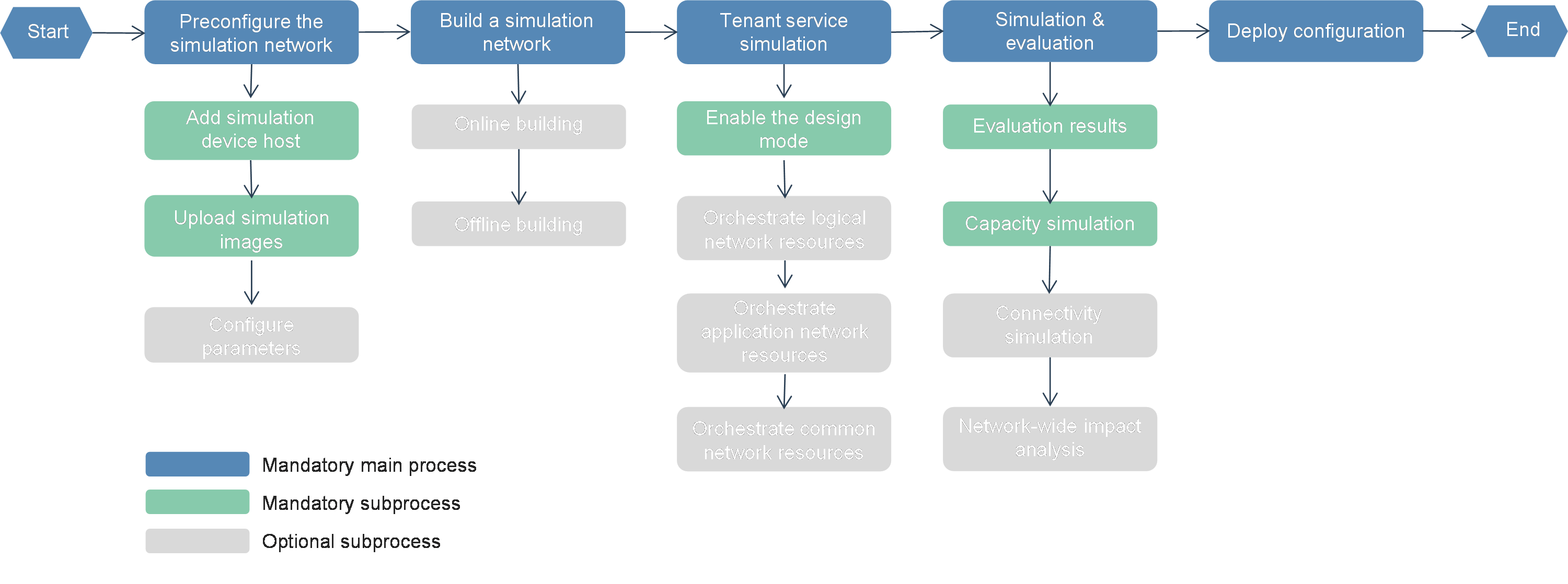
Configuration flowchart
Figure 62 Configuration flowchart
Procedures
Preconfigure the simulation network
Add simulation device hosts
1. Log in to the controller. Navigate to the Automation > Data Center Networks > Simulation > Build Simulation Network page. Click Preconfigure. The simulation device host management page opens.
2. Click Add. In the dialog box that opens, configure the host name, IP address, username, and password.
Figure 63 Adding simulation device hosts

3. Click Apply.
|
|
NOTE: · A host can be incorporated by only one cluster. · The controller allows you to incorporate simulation device hosts as a root user or non-root user. To incorporate simulation device hosts as a non-root user, first add the non-root user permission by executing the sudo ./addPermission.sh username command in the SeerEngine_DC_DTN_HOST-version/tool/ directory of the decompressed simulation device host package. · If the settings of a simulation device host are modified, you must re-incorporate the simulation device host. |
Upload simulation images
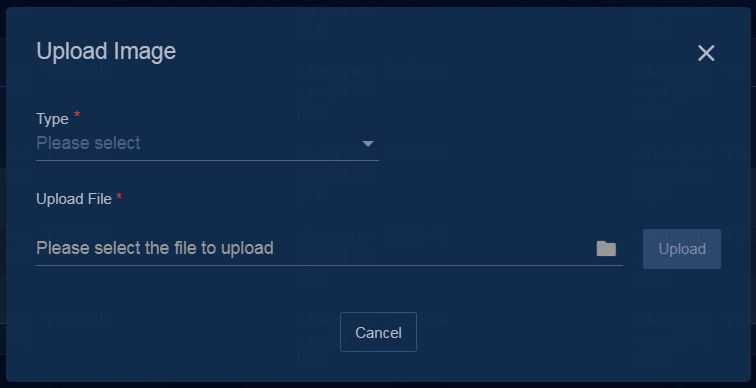
1. Log in to the controller. Navigate to the Automation > Data Center Networks > Simulation > Build Simulation Network page. After clicking Preconfigure, click the Manage Simulation Images tab. The page for uploading simulation images opens.
2. Click Upload Image. In the dialog box that opens, select the type of the image to be uploaded and image of the corresponding type, and then click Upload.
Figure 64 Uploading simulation images
Configure parameters-Deploy the license server
The license server provides licensing services for simulated devices. Support the following deployment modes.
· (Recommended) Use the License Server that has already been deployed on the controller (the IP protocol type of the License Server must be consistent with the IP protocol type of the MACVLAN network used by the DTN components).
· Separately deploy a license server for the simulated devices, If there are multiple simulation device hosts, upload the package to any server.
|
|
NOTE: · When deploying the H3Linux 1.0 operating system on a Unified Platform, if the Install License Server option is selected, the corresponding node will automatically install the License Server after the software deployment. · If you need to install the License Server separately, see H3C License Server Installation Guide. |
Configure parameters-Configure parameters
1. Navigate to the Automation > Data Center Networks > Simulation > Build Simulation Network page. Click Preconfigure. On the page that opens, click the Parameters tab.
2. On this page, you can view and edit the values for the simulation network M-LAG building mode, device information (flavor), UDP port, and address pool parameters, and configure license server parameters.
|
|
NOTE: As a best practice, select the flavor named 1_cpu_4096MB_memory_2048MB_storage. The flavor named 1_cpu_2048MB_memory_2048MB_storage is applicable in the scenario where the number of each type of logical resources (vRouters, vNetworks, or vSubnets) is not greater than 1000. |
3. Click Apply.
Configure parameters-Retain ports in the configuration file
1. Access the operating system of the simulation device host.
2. Execute the vi /etc/sysctl.conf command to access the sysctl.conf configuration file. Add the following contents to the configuration file.
NOTE: Use the port range in the following configuration as an example. In an actual configuration file, the retained port range must be the same as the default UDP port range on the simulation network preconfiguration page.
[root@node1 ~]# vi /etc/sysctl.conf
…
net.ipv4.ip_local_reserved_ports=10000-15000
3. If you change the UDP port range on the simulation network preconfigure page, change also the retained port range in the sysctl.conf configuration file and save the change.
4. Execute the /sbin/sysctl –p command for the change to take effect.
5. Execute the cat /proc/sys/net/ipv4/ip_local_reserved_ports command to view the retained ports. If the returned result is consistent with your change, the change is successful.
Build a simulation network
Online building
1. Log in to the controller. Navigate to the Automation > Data Center Networks > Simulation > Build Simulation Network page.
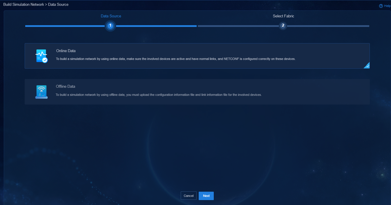
2. Click Build on the page for building a simulation network. Select the Online Data and click Next.
Figure 65 Selecting a data source
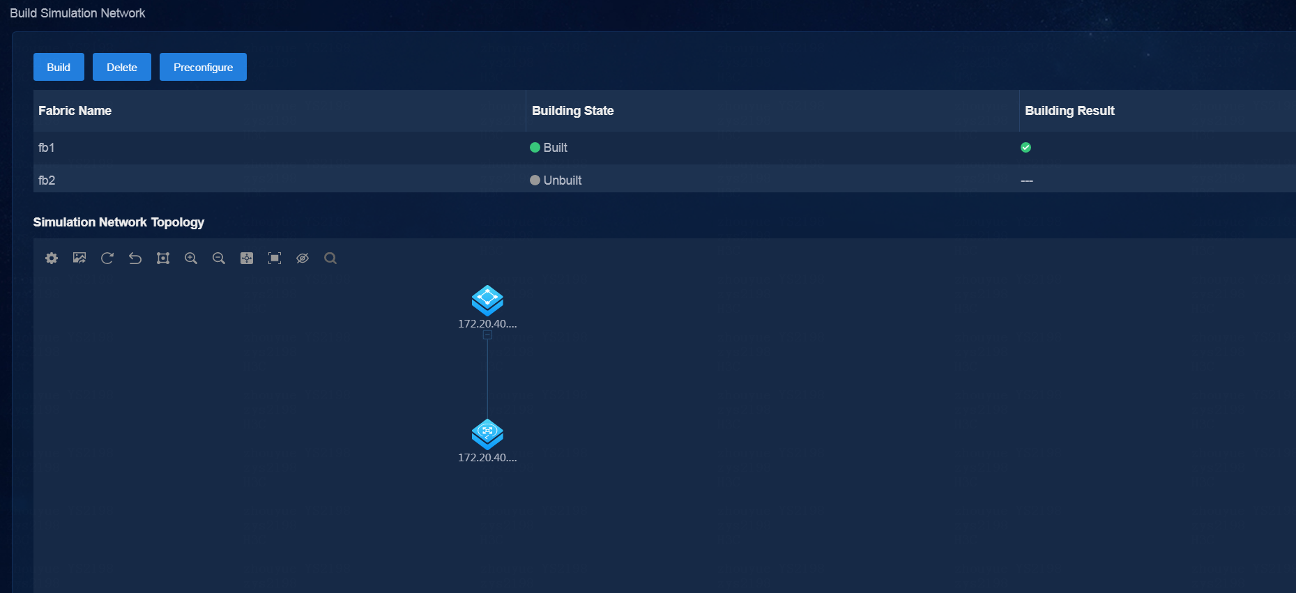
3. Select fabrics as needed, and click Start Building to start building the simulation network. You can select multiple fabrics.
Figure 66 Selecting fabrics
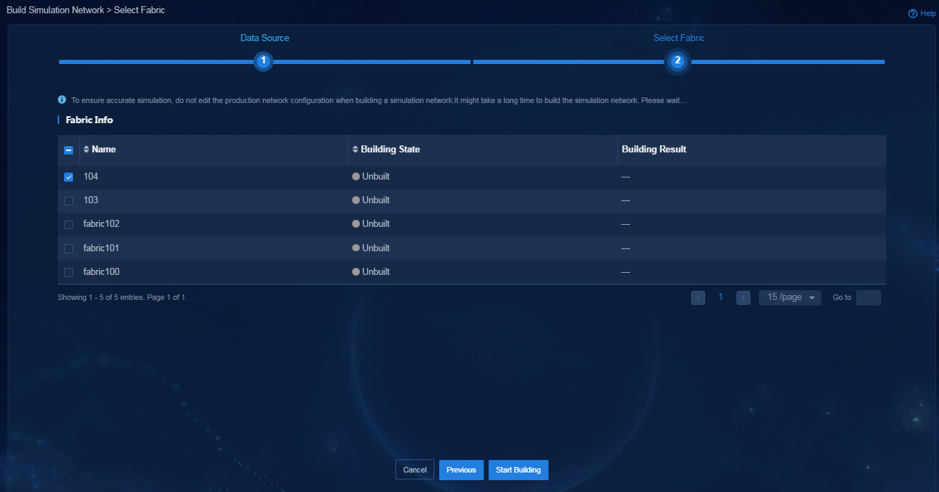
After the simulation network is built successfully, its state is displayed as Built on the page.
Figure 67 Simulation network built successfully
4. After the simulation network is built successfully, you can view the simulated device information:
¡ The simulated device running state is Active.
¡ The device model is displayed correctly on the real network and the simulation network.
The VMs in the simulation network model are created on the host created. If multiple hosts are available, the controller selects a host with optimal resources for creating VMs.
Figure 68 Viewing simulated devices

Offline building
To use the offline data to build a simulation network, first back up and restore the environment, and obtain the link information and device configuration files before building a simulation network. More specifically:
Back up the SeerEngine-DC environment
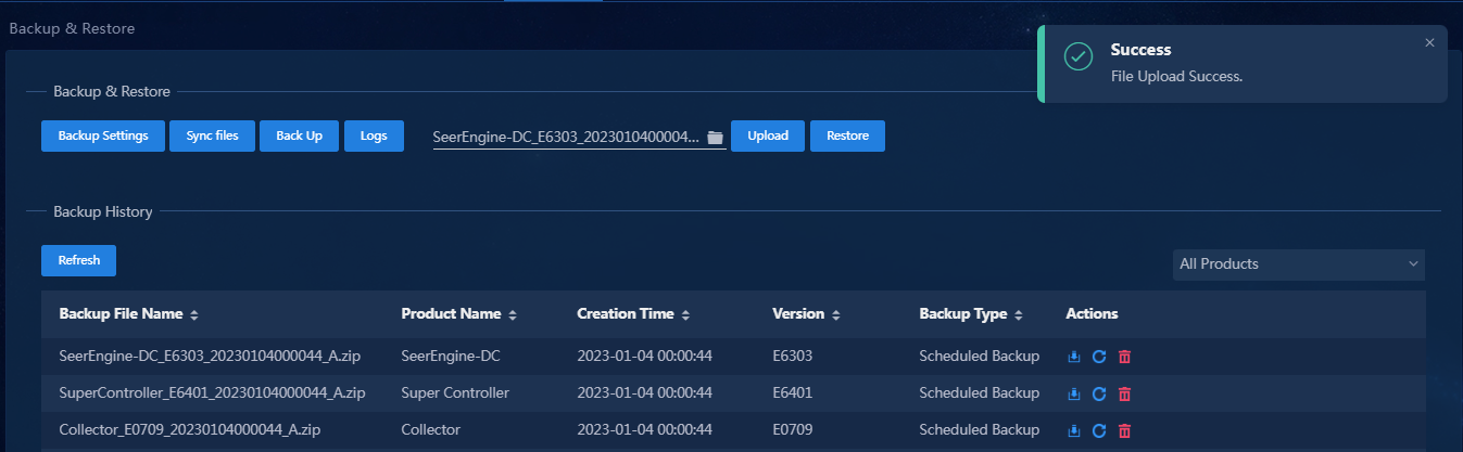
1. Log in to the controller that is operating normally. Navigate to the System > Backup & Restore page.
2. Click Start Backup. In the dialog box that opens, select SeerEngine-DC. Click Backup to start backup.
Figure 69 Back up SeerEngine-DC
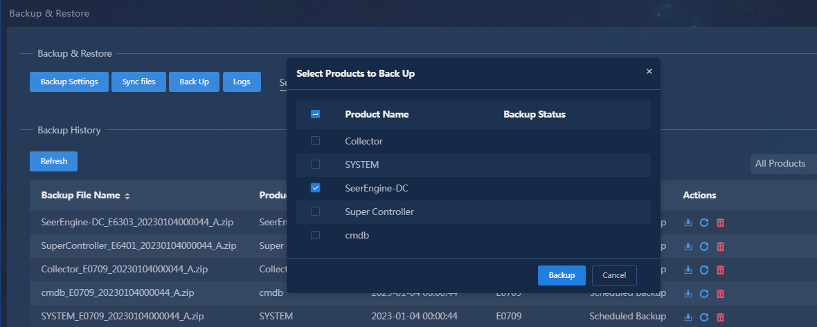
3. After the backup is completed, click Download in the Actions column for the backup file to download it.
Obtain the link information file
1. In the address bar of the browser, enter http://ip_address:port/sdn/ctl/rest/topologydata/all_link_info.
Link information of all fabrics in the environment will be displayed.
¡ ip_address: IP address of the controller.
¡ port: Port number.
Figure 70 Link info
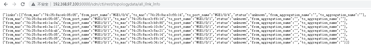
2. Copy the obtained link information to a .txt file, and save the file.
The file name is not limited. The file is the link information file.
Obtain the device configuration file
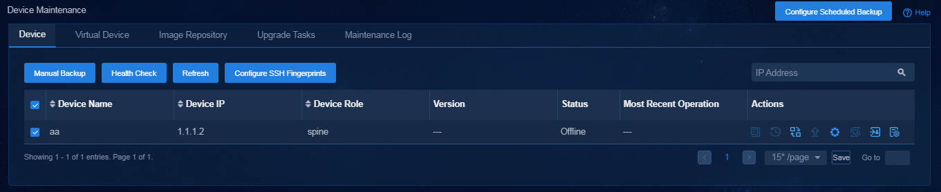
1. Log in to the controller that is operating normally. Navigate to the Automation > Configuration Deployment > Device Maintenance > Physical Devices page.
2. Select all devices, and click Manual Backup.
Figure 71 Manually backing up all device information
3. Click the ![]() icon in the Actions column for a device. The configuration file
management page opens. Click Download to download
the configuration file of the specified device to your local host.
icon in the Actions column for a device. The configuration file
management page opens. Click Download to download
the configuration file of the specified device to your local host.
4. Compress all download configuration files into one .zip package.
The .zip package name is not limited. The .zip package is the device configuration file.
Restore the SeerEngine-DC environment
1. Log in to the environment where you want to build a simulation network based on offline data.
2. Navigate to the System > Backup & Restore page. Use the backup file to restore the environment.
Figure 72 Restore the environment
Build a simulation network
1. Log in to the controller. Navigate to the Automation > Data Center Networks > Simulation > Build Simulation Network page.
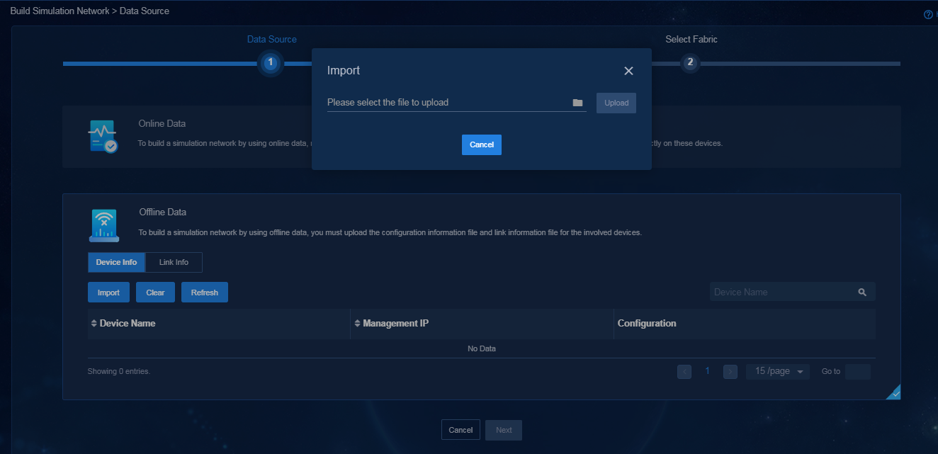
2. Click Build on the page for building a simulation network and select Offline Data. After you select this option, perform the following tasks:
- On the Device Info page, click Import. In the dialog box that opens, import and upload the device configuration file.
Figure 73 Importing and uploading the device configuration file
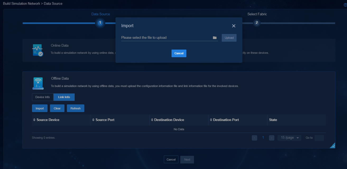
- Down Link Info page, click Import. In the dialog box that opens, import and upload the link information file.
Figure 74 Importing and uploading the link information file
- Click Next.
3. Select fabrics as needed, and click Start Building to start building the simulation network. You can select multiple fabrics.
Figure 75 Selecting fabrics

After the simulation network is built successfully, its state is displayed as Built on the page.
Figure 76 Simulation network built successfully

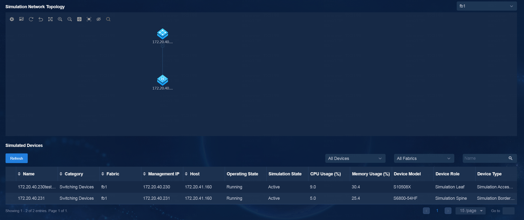
4. After the simulation network is built successfully, you can view the simulated device information:
¡ The simulated device running state is Active.
¡ The device model is displayed correctly on the real network and the simulation network.
The VMs in the simulation network model are created on the host created. If multiple hosts are available, the controller selects a host with optimal resources for creating VMs.
Figure 77 Viewing simulated devices
Simulate the tenant service
Enable the design mode for the tenant
1. Navigate to the Automation > Data Center Networks > Simulation > Tenant Service Simulation page.
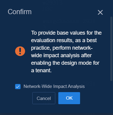
2. Click the design mode switch for the specified tenant. A confirmation dialog box opens to ask whether you want to perform network-wide impact analysis.
¡ Select the Network-Wide Impact Analysis option, and click OK to access the network-wide impact analysis page.
As a practice to provide baseline values for the evaluation results, perform network-wide impact analysis.
Figure 78 Performing network-wide impact analysis as a best practice
¡ If you click OK without selecting the Network-Wide Impact Analysis option, the design mode will be enabled.
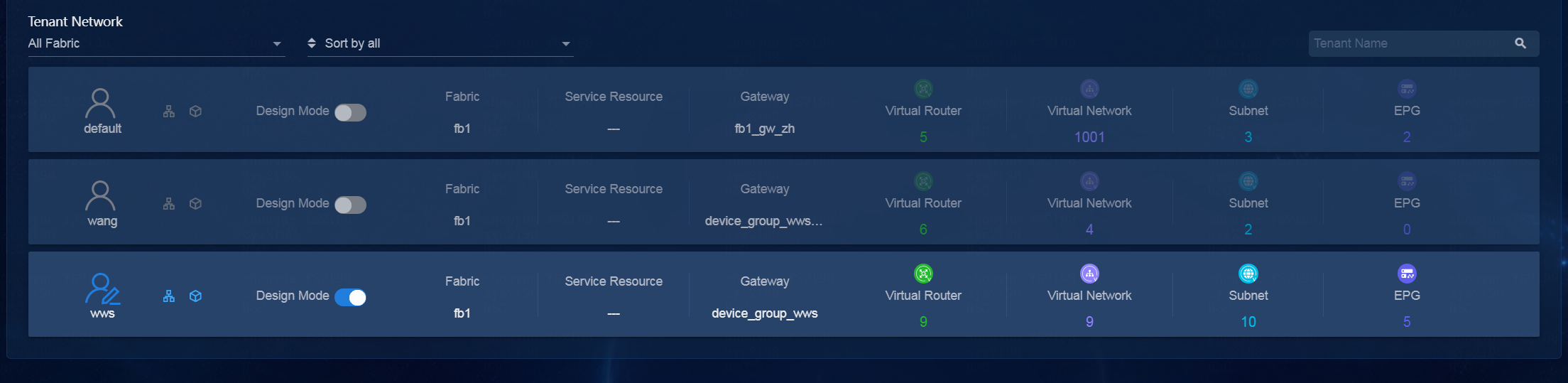
After design mode is enabled for a
tenant, the tenant icon becomes ![]() , which means that
the tenant is editable. After design mode is disabled for a tenant, the tenant
icon becomes
, which means that
the tenant is editable. After design mode is disabled for a tenant, the tenant
icon becomes ![]() , which indicates that the tenant is not editable.
, which indicates that the tenant is not editable.
|
|
NOTE: You can enable the design mode and then perform tenant service simulation only when the simulation network is built normally. |
Figure 79 Enabling the design mode for the tenant
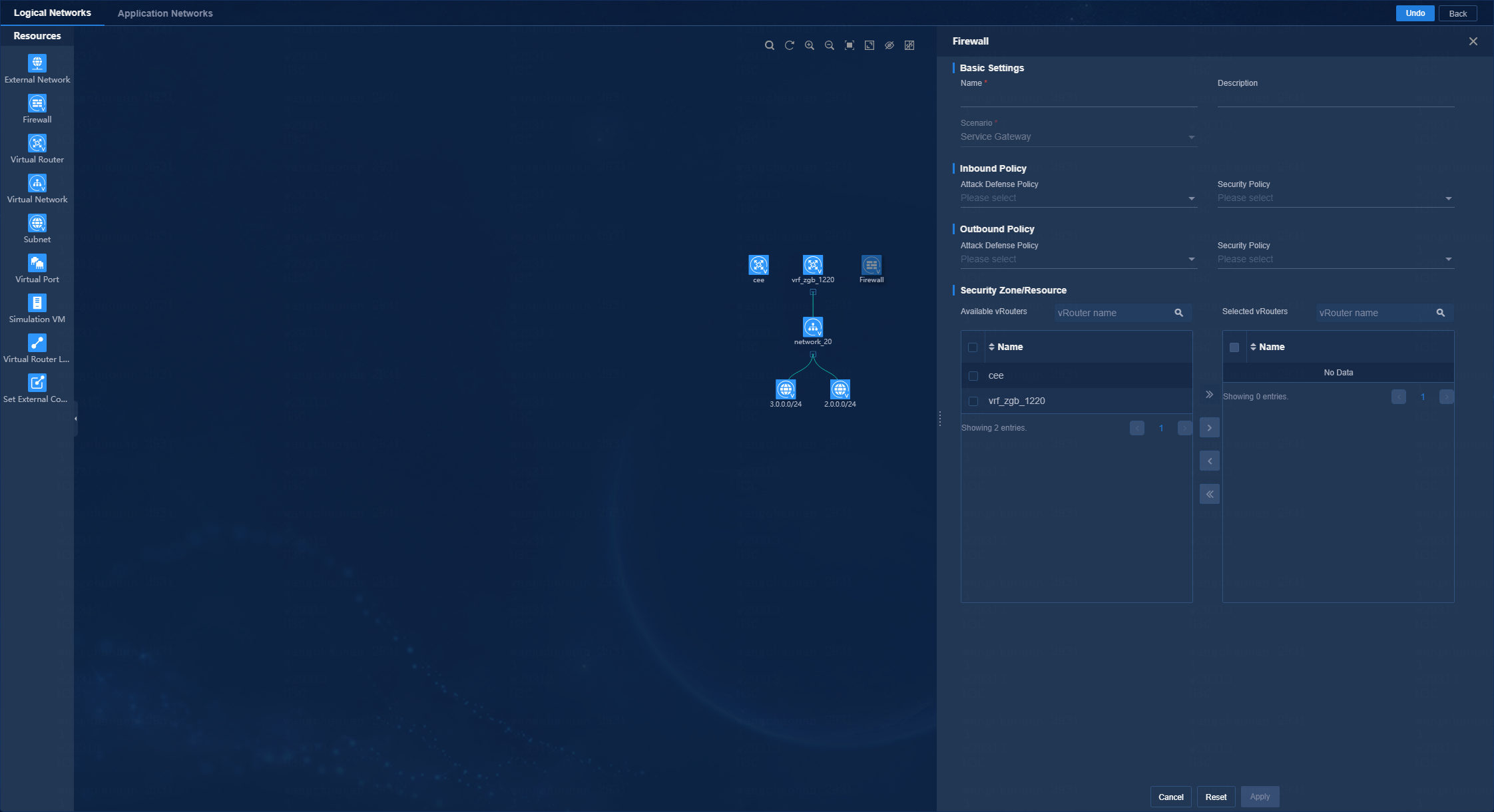
Orchestrate logical network resources
1. Click the icon for the tenant to access the Tenant Service Simulation (Tenant Name) > Logical Networks page. On this page, you can perform tenant service simulation.
2. On the logical network page, you can perform the following operations:
¡ Drag a resource icon in the Resources area to the canvas area. Then, a node of this resource is generated in the canvas area, and the configuration panel for the resource node opens on the right.
¡ In the canvas area, you can adjust node locations, bind/unbind resource, and zoom in/out the topology.
Figure 80 Logical networks
Orchestrate application network resources
1. Click the icon for the tenant to access the Tenant Service Simulation (Tenant Name) > Logical Networks page.
2. Click the Application Networks tab to access the application network orchestration page and configure the service resources for the specified application network.
Orchestrate common network resources
On the tenant service simulation page, click the service resource link in the common network settings area to access the service resource management page and configure the specified service resources.
Evaluate the simulation
After resource orchestration, click Simulate & Evaluate on the tenant service simulation page. In the dialog box that opens, click Start. After simulation & evaluation is completed, click Simulation Results to access the simulation result page. From this page, you can view the evaluation results and capacity simulation results. You can also perform connectivity simulation and network-wide impact analysis based on traffic simulation requirements.
Simulation result
This feature displays a quantified table of simulation report scores. You can have a more intuitive understanding of the comprehensive simulation & evaluation score and the evaluation results of service changes from various perspectives.
Figure 81 Evaluation results
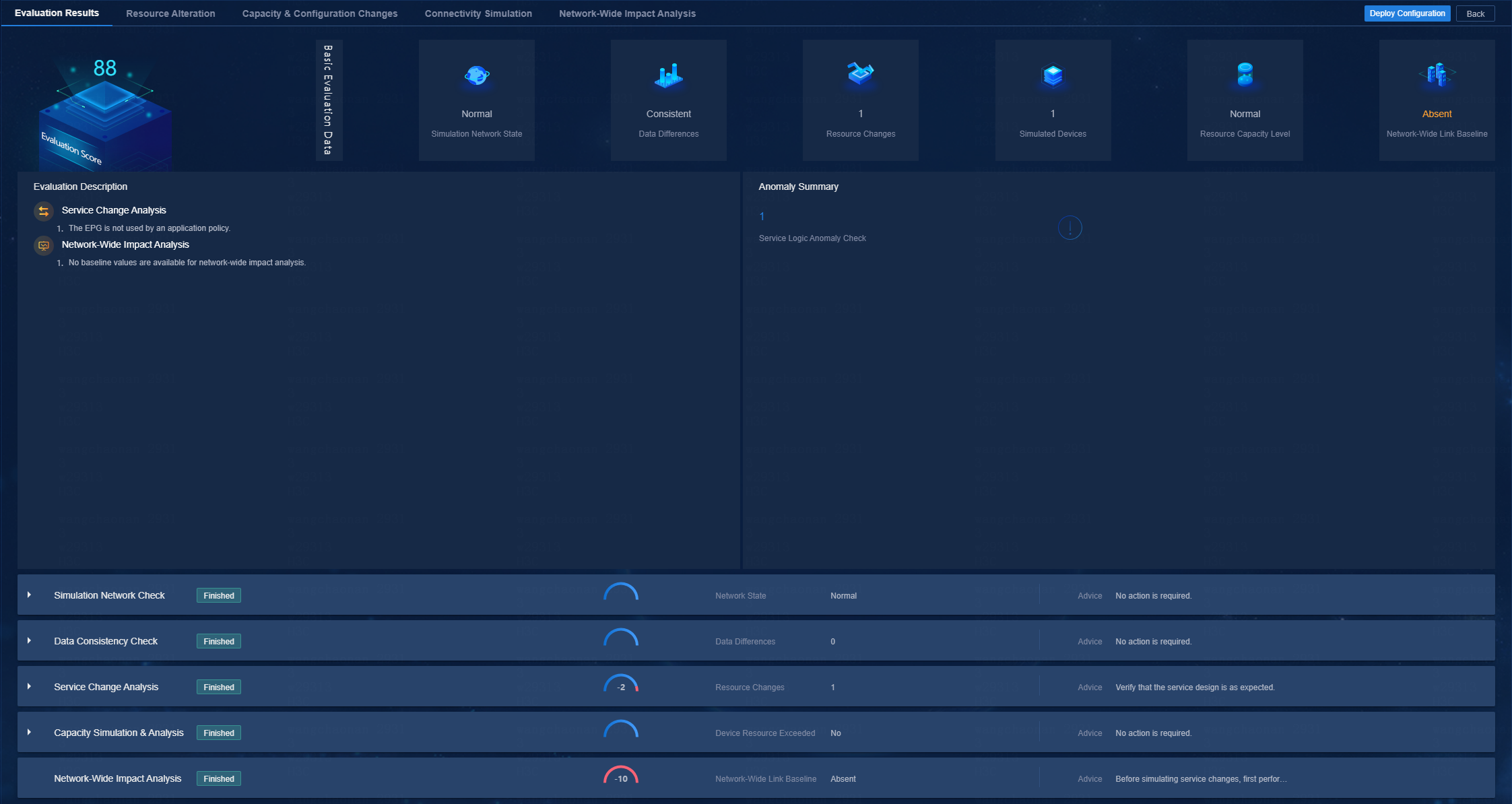
· Simulation network check—Evaluate the health of the simulation networks based on factors such as CPU and memory usage of simulated devices.
Figure 82 Simulation network check
![]()
· Data consistency check—Evaluate the service differences between production and simulation networks.
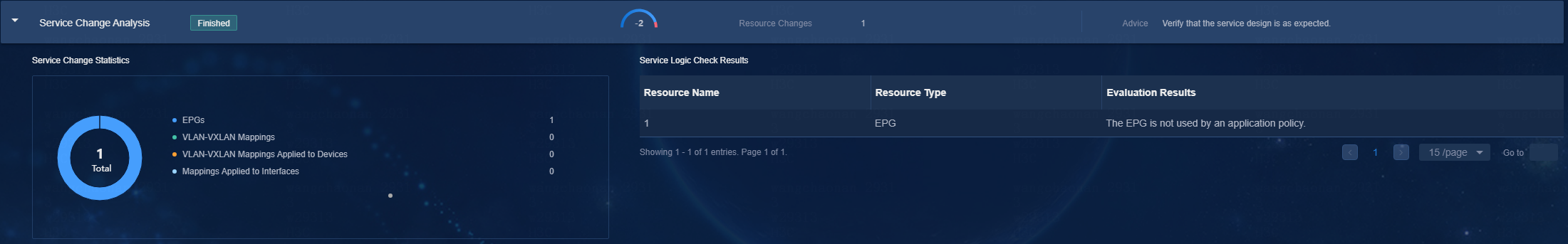
· Service change analysis—Analyze from the perspective of whether the service changes are reasonable.
Figure 83 Service change analysis
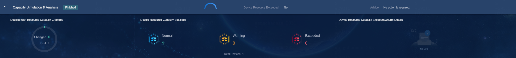
· Capacity simulation & analysis—Evaluate from the perspective of resource capacity usage.
Figure 84 Capacity simulation & analysis
· Network-wide impact analysis—Evaluate the existence of baseline values for network-wide impact analysis.
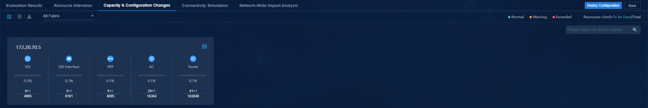
Capacity and configuration changes
This function is used to calculate the device resource consumption and configuration deployment caused by this service change and present them in multiple views in the form of differences.
· Resource capacity
The resource capacity evaluation function evaluates the resource consumption resulting from this service change. By analyzing the total capacity, consumed capacity, and capacity to be consumed of physical device resources on the network, this feature determines whether this service change will fall into the device resource blackhole.
· Configuration changes
This feature mainly displays the NETCONF and CLI configuration differences before and after simulation & evaluation.
Figure 85 Capacity and configuration changes
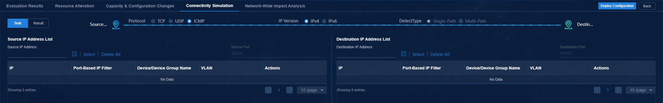
Connectivity simulation
On the page, you can manually select ports for detection according to service requirements. The connectivity simulation feature simulates TCP, UDP, and ICMP protocol packets to detect connectivity between ports.
Figure 86 Connectivity detection
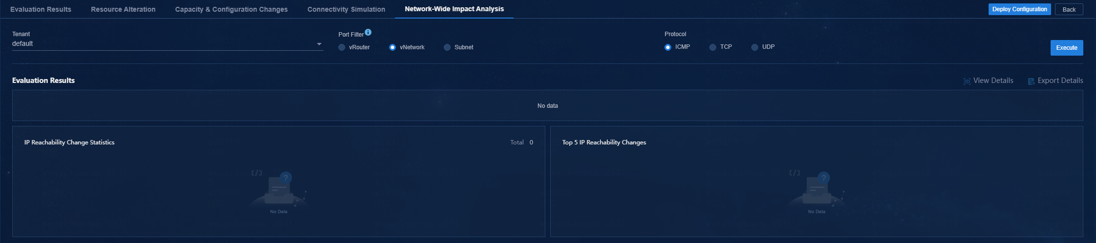
Network-wide impact analysis
From the perspective of the overall service, network-wide impact analysis can quickly assess the impact of service changes on the connectivity of networks, and identify the links with state changes. This feature compares the initial state results before this simulation with the network-wide impact analysis results of this simulation, and outputs the comparison results. Then, you can quickly view the link state changes of the entire network.
In the current software version, network-wide impact analysis supports multi-tenant, multi-port filters (vRouters, vNetworks, and subnets) and multiple protocols (ICMP, TCP, and UDP).
Figure 87 Network-wide impact analysis
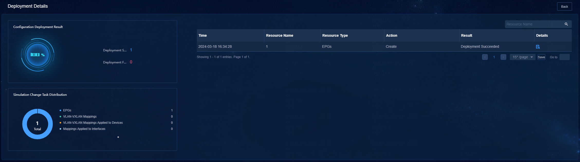
Deploy configuration
You can click Deploy Configuration to deploy the service configuration to real devices when the simulation evaluation result is as expected. Additionally, you can view details on the deployment details page.
Figure 88 Viewing deployment details
Register and install licenses
After you install the controller, you can use its complete features and functions for a 180-day trial period. After the trial period expires, you must get the controller licensed.
Install the activation file on the license server
For the activation file request and installation procedure, see H3C Software Products Remote Licensing Guide.
Obtain DTN component licenses
After installing the license for the product on the license server, you only need to connect to the license server from the license management page to obtain the license authorization. To do that, perform the following tasks:
1. Log in to Unified Platform. On the top navigation bar, click System, and then select License Management > License Information.
2. Configure the parameters for the license server as described in Table 22.
Table 22 License server parameters
3. Click Connect to connect the DTN component to the license server.
The DTN component will automatically obtain licensing information after connecting to the license server.
Obtain simulation device licenses
After installing the license for the DTN component on the license server, you only need to connect to the DTN server from the license management page to obtain the license authorization. To do that, perform the following tasks:
1. Log in to the controller. Navigate to the Automation > Data Center Networks > Simulation > Build Simulation Network page. Click Preconfigure.
2. Configure the parameters for the license server as described in Table 23.
Table 23 License server parameters
|
Item |
Description |
|
IP Address |
Specify the IP address configured on the license server used for internal communication in the cluster. |
|
Port |
Specify the service port number of the license server. The default value is 5555. |
|
Username |
Specify the client username configured on the license server. |
|
Password |
Specify the client password configured on the license server. |
3. Click Connect to connect the simulation device to the license server.
The simulation device will automatically obtain licensing information after connecting to the license server.
Back up and restore the DTN configuration
The DTN component is an independent microservice in the controller. To back up and restore the DTN component, simply back up and restore the controller on Unified Platform. For more information, see H3C Unified Platform Deployment Guide.
Upgrade and uninstall software
Upgrade the DTN
DTN component
|
|
CAUTION: · After the DTN component is upgraded, check the simulation software version and proceed with its upgrade if necessary. · Before upgrading DTN, first upgrade the controller. The DTN and DC versions must be consistent after the upgrade. · If the simulation network construction page has a display issue after the DTN component is upgraded, clear the browser cache and log in again. · After upgrading the DTN component from E6102 or earlier to E6103 or later, you must reinstall the operating system and reconfigure settings for simulation device hosts and delete the original hosts from the simulation network and then reincorporate the hosts. For how to install the operating system and configure settings for simulation device hosts, see H3C SeerEngine-DC Simulation Network Environment Deployment Guide. · After upgrading the DTN component from E6202 or earlier to E6203 or later, you must uninstall and reconfigure the simulation device hosts and delete the original hosts from the simulation network and then reincorporate the hosts. For how to uninstall and configure simulation device hosts, see H3C SeerEngine-DC Simulation Network Environment Deployment Guide. · After upgrading the DTN component from E6302 or earlier to E6302 or later, you must delete the simulation network from all fabrics and then reconstruct the simulation network. · The DTN component does not support direct upgrade from a version earlier than E6501 to E6501 or later. For such an upgrade, you must first remove the old version and then install the new version. |
The components can be upgraded on Unified Platform with the configuration retained.
To upgrade the DTN:
1. Log in to Unified Platform. Click System > Deployment.
Figure 89 Deployment page
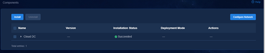
2. Click the left chevron button ![]() for Cloud DC to
expand component information. Then upgrade SeerEngine-DC and DTN.
for Cloud DC to
expand component information. Then upgrade SeerEngine-DC and DTN.
3. Click the ![]() icon for the DTN
component to upgrade the DTN component.
icon for the DTN
component to upgrade the DTN component.
4. # Upload and select the installation package.
5. # Click Upgrade.
6. # If the upgrade fails, click Roll Back to roll back to the previous version.
Hot patch the DTN
On the United Platform, you can hot patch the DTN with the configuration retained. Hot patching the DTN might cause service interruption. To minimize service interruption, select the time to hot patch the DTN carefully.
1. Log in to Unified Platform. Click System > Deployment.
Figure 90 Deployment page
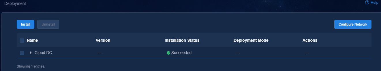
2. Click the left chevron button ![]() of the DTN to
expand DTN information, and then click the hot patching icon
of the DTN to
expand DTN information, and then click the hot patching icon ![]() .
.
3. Upload the patch package and select the patch of the required version, and then click Upgrade.
4. If the upgrade fails, click Roll Back to roll back to the previous version or click Terminate to terminate the upgrade.
Uninstall DTN
DTN component
The DTN component can be uninstalled separately. To uninstall the DTN component only:
1. Log in to Unified Platform. Click System > Deployment.
2. Click the ![]() icon to the left of the DTN
component and then click Uninstall.
icon to the left of the DTN
component and then click Uninstall.
Figure 91 Uninstalling the DTN component
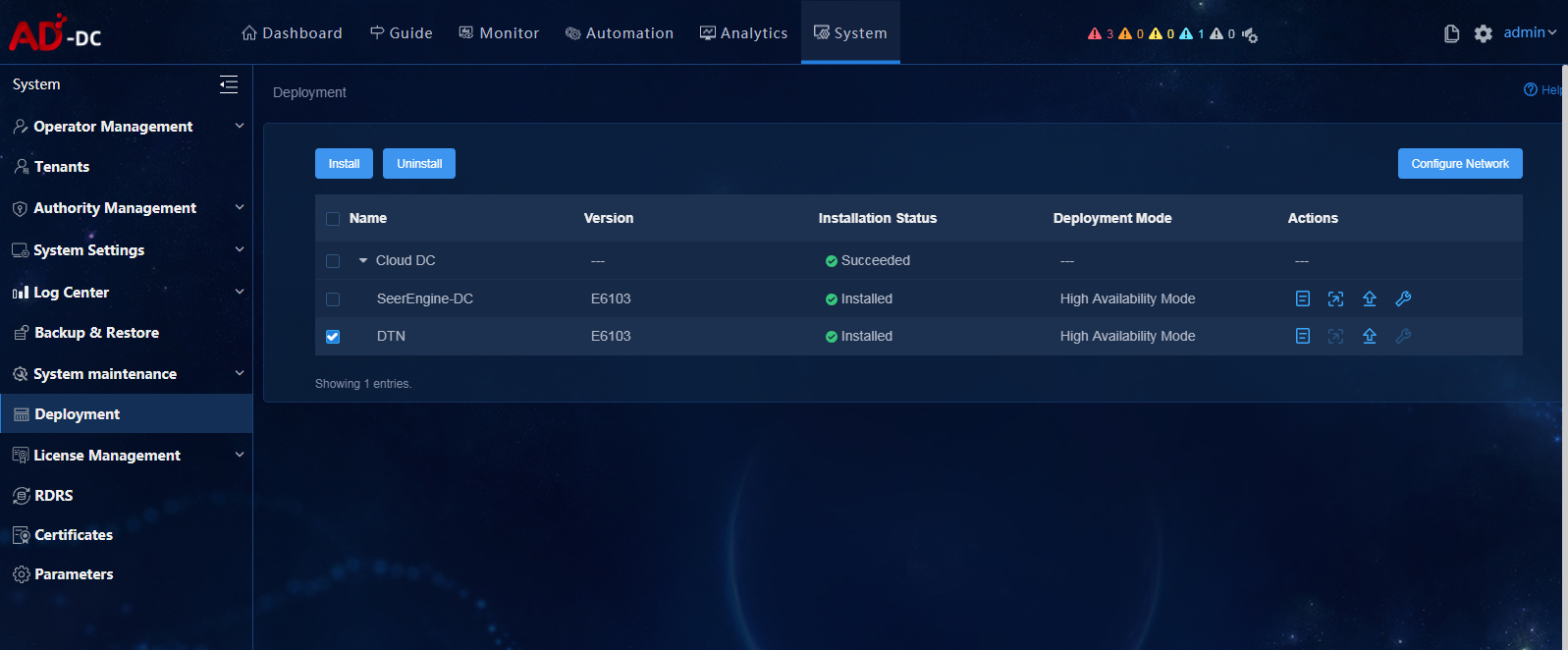
Uninstall a hot patch
1. Log in to Unified Platform. Click System > Deployment.
2. Select a patch, and then click Uninstall.
Figure 92 Uninstalling a hot patch
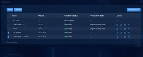
Upgrade the simulation device hosts
Upgrade the simulation device host deployed in standalone mode
1. Obtain the new version of the simulation device host installation package, upload it to the server, and decompress it. The package is named in the SeerEngine_DC_DTN_HOST-version.zip format.
[root@host01 root]# unzip SeerEngine_DC_DTN_HOST-E6205.zip
2. Execute the chmod command to assign permissions to the user.
[root@host01 root]# chmod +x -R SeerEngine_DC_DTN_HOST-E6205
3. Access the SeerEngine_DC_DTN_HOST-version/ directory of the decompressed installation package, and then execute the ./upgrade.sh command to upgrade the host.
[root@host01 SeerEngine_DC_DTN_HOST-E6205]# ./upgrade.sh
check network service ok.
check libvirtd service ok.
check management bridge ok.
check sendip ok.
check vlan interface ok.
Complete!
|
|
IMPORTANT: To upgrade the DTN component from E6202 or an earlier version to E6203 or later, you must uninstall the simulation device host and then reconfigure it. After the upgrade, you must delete the original host from the simulation network and then re-incorporate it. |
Upgrade the virtualization simulation device host deployed in convergence mode
1. Access the Deploy > Convergence Deployment page of Matrix.
2. Click the ![]() button for the
virtualization simulation device host to access the upgrade page.
button for the
virtualization simulation device host to access the upgrade page.
Figure 93 Upgrading the virtualization simulation device host on the convergence deployment page
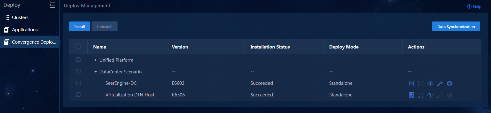
3. Upload the installation package and select the package to be deployed.
4. Click Upgrade to upgrade the virtualization simulation device host.
|
|
NOTE: After upgrading the virtualization simulation device host, rebuild the simulation network. |
Figure 94 Upgrading virtualization simulation device hosts
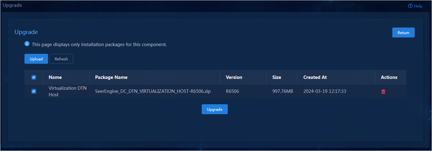
Uninstall the simulation device host
Uninstall the simulation device host deployed in standalone mode
|
|
IMPORTANT: · Execution of the simulation device host uninstall script will cause the network service to restart and the SSH connection to disconnect. To avoid this situation, uninstall a simulation device host from the remote console of the server or VM. · To uninstall a simulation device host in E6202 and an earlier version, you are to execute the ./uninstall.sh management_nic service_nic command in the specified directory. |
To uninstall a host, access the SeerEngine_DC_DTN_HOST-version/ directory and execute the ./uninstall.sh command.
[root@host01 SeerEngine_DC_DTN_HOST-E6205]# ./uninstall.sh
Uninstalling ...
Bridge rollback succeeded.
Restarting network,please wait.
Complete!
Uninstall the virtualization simulation device host deployed in convergence mode
1. Access the Deploy > Convergence Deployment page of Matrix.
2. Select the virtualization simulation device host option, and click Uninstall to uninstall the specified component.
Figure 95 Uninstall the virtualization simulation device host
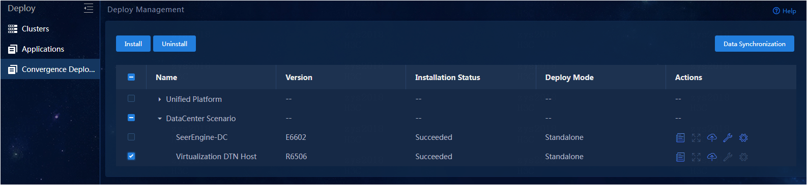
3. Use the yum remove `rpm -qa | grep libvirt` command to uninstall the libvirt dependency package.
Network changes
About this task
If IP address conflict exists or the network plan needs to be changed, for example, equipment room relocation or subnet mask change after component deployment, you can change networks for the components. This section describes how to change network settings for the DTN components.
Procedure
|
|
CAUTION: · Network change for a component can cause service interruption. Please be cautious. |
To edit network settings:
1. Log in to Unified Platform. Click System > Deployment.
Figure 96 Deployment page
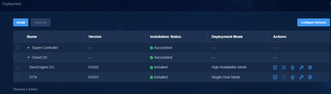
2. Click the left chevron button ![]() for the component to
expand component information.
for the component to
expand component information.
3. Click the![]() icon for the DTN component.
icon for the DTN component.
4. Select a network.
5. Click Next.
6. Review the parameters, and then click OK. The network editing progress is displayed on the page.
7. If network change fails, roll back the network settings or exit the network change process.
Actions after network changes
After network changes, manually edit some IP address-related configurations.
Check the DTN network
For simulation to operate correctly after you edit DTN network settings, make sure the DTN component and DTN node are reachable to each other.
FAQ
Deploying a simulation device host on a VM
When I deploy a simulation device host on a VMware ESXI VM, how can I enable the nested virtualization feature for VMware and the simulation device host?
To enable the nested virtualization feature for VMware and the simulation device host, perform the following tasks.
Enabling the nested virtualization feature for Vmware
1. Log in to the back end of the host of VMware. View the file named config in the /etc/vmware directory.
Figure 97 File named config in the /etc/vmware directory
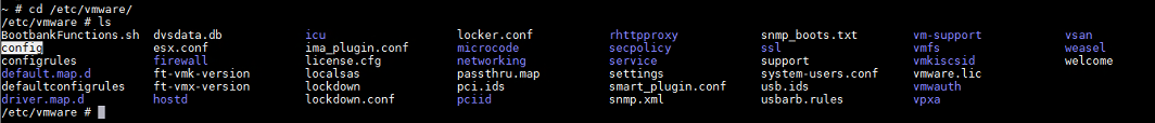
2. Execute the vi command to enter the configuration file named config. Add the following configuration to the end of the configuration file: vhv.enable = ”TRUE”
Figure 98 Editing the configuration file named config
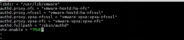
3. After the operation, execute the reboot command to restart the ESXi server.
Enabling the nested virtualization feature on the simulation device host:
1. In the back end of the VMware host, enter the /vmfs/volumes folder.
In this folder, there is a folder corresponding to the simulation device host. The folder name is the simulation device host ID.
Figure 99 Viewing the simulation device host folder name
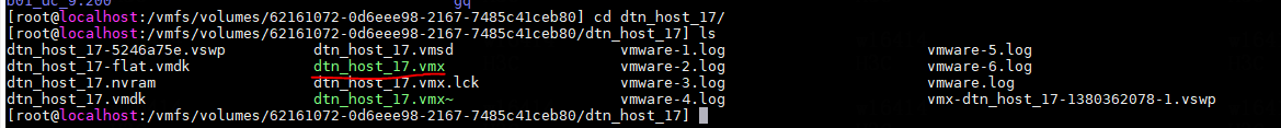
2. Enter the simulation device host folder, and execute the vim command to edit the dtn_host.vmx file. Add the following configuration to the end of the configuration file: vhv.enable = ”TRUE”
3. After the configuration is completed, add a port group on VMware. The port group name is DTN Network in this example. Make sure the VLAN ID of the newly added port group is 4095 (the VLAN ID of 4095 means all VLANs are permitted).
Figure 100 Adding a port group
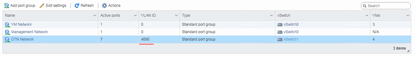
4. After the port group is added, change the port group bound to the NIC of the simulation device host.
Figure 101 Configuring the simulation device host NIC
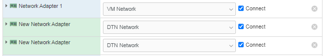
|
|
NOTE: · The network bound to the port group named DTN Network is used as the simulation management network and simulated device service network. The network bound to the port group named VM Network is used as the node management network. · If multiple simulation device hosts are bound to the port group named DTN Network, make sure each physical network associated with the port group is reachable. · When deploying DTN components and simulation device hosts (or simulation devices) across three layers, it is necessary to assign different port groups for the DTN components and simulation device hosts, and designate different vSwitches for the port groups. |
When I deploy a simulation device host on a CAS VM, how can I enable the nested virtualization feature for CAS and the simulation device host?
To enable the nested virtualization feature for CAS and the simulation device host, perform the following tasks.
Enabling the nested virtualization feature for CAS
1. Power off the VM on CAS.
2. Log in to the back end of the host where CAS resides. Execute the following command to identify whether the nested virtualization feature is enabled. In the command output, the value of N indicates disabled and the value of Y indicates enabled. If Y is displayed, skip the following steps.
[root@cvknode2 ~]# cat /sys/module/kvm_intel/parameters/nested
N
3. Execute the touch /etc/modprobe.d/kvm-nested.conf command to create a file named kvm-nested.conf.
Figure 102 Viewing the created file named kvm-nested.conf
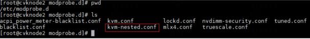
4. Edit the file named kvm-nested.conf, and add the following contents:
options kvm-intel nested=1
options kvm-intel enable_shadow_vmcs=1
options kvm-intel enable_apicv=1
options kvm-intel ept=1
5. After editing the file, reload kvm_intel.
[root@cvknode2 modprobe.d]# modprobe -r kvm_intel //Remove kvm_intel. Shut down all VMs before this operation
[root@cvknode2 modprobe.d]# modprobe -a kvm_intel //Load kvm_intel
Enabling the nested virtualization feature on the simulation device host
1. In the back end of the CAS host, execute the virsh list --all command to view all VMs in CAS and find the target simulation device host.
Figure 103 Viewing the simulation device host folder name
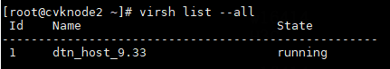
2. Execute the virsh edit dtn_host_name command to edit VM settings. The following example edits simulation device host dtn_host_9.33.
Figure 104 Edit configuration of simulation device host dtn_host_9.33
![]()
a. Edit CPU: Add the mode='host-passthrough' attribute.
Figure 105 Adding host-passthrough for the CPU mode
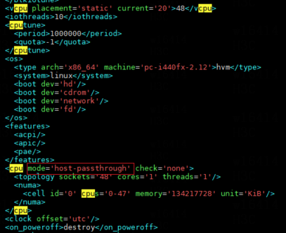
a. Enter CAS, and add a vSwitch.
b. After the vSwitch is added, change the vSwitch bound to the NIC of the simulation device host.
|
|
NOTE: · The network bound to vSwitch dtn_network is used as the simulation management network and simulated device service network. The network bound to vSwitch vswitch0 is used as the node management network. · If multiple simulation device hosts are bound to vSwitch dtn_network, make sure each physical network associated with the vSwitch is reachable. · When deploying DTN components and simulation device hosts (or simulation devices) across three layers, it is necessary to allocate separate virtual switches for the DTN components and simulation device hosts. |
Why do I still fail to log in to VMware ESXi even when the correct username and password are entered?
This issue does not belong to the simulation function issues, but is caused by the protection mechanism of VMware ESXi.
If the number of incorrect input attempts for VMware login exceeds the threshold (5 by default), the account will be locked and login will be prohibited for a period of time. Even if you enter the correct username and password at this time, VMware ESXi will still prompt that login cannot be completed due to incorrect username and password.
