- Table of Contents
- Related Documents
-
| Title | Size | Download |
|---|---|---|
| 01-Text | 1.31 MB |
1 Hardware information and specifications of pRRU5314
About H3C 5G extended pico stations
About hybrid copper-fiber cables
Hybrid copper-fiber cable specifications
Assembling a hybrid copper-fiber cable
Making an Ethernet twisted pair cable
1 Hardware information and specifications of pRRU5314
About H3C 5G extended pico stations
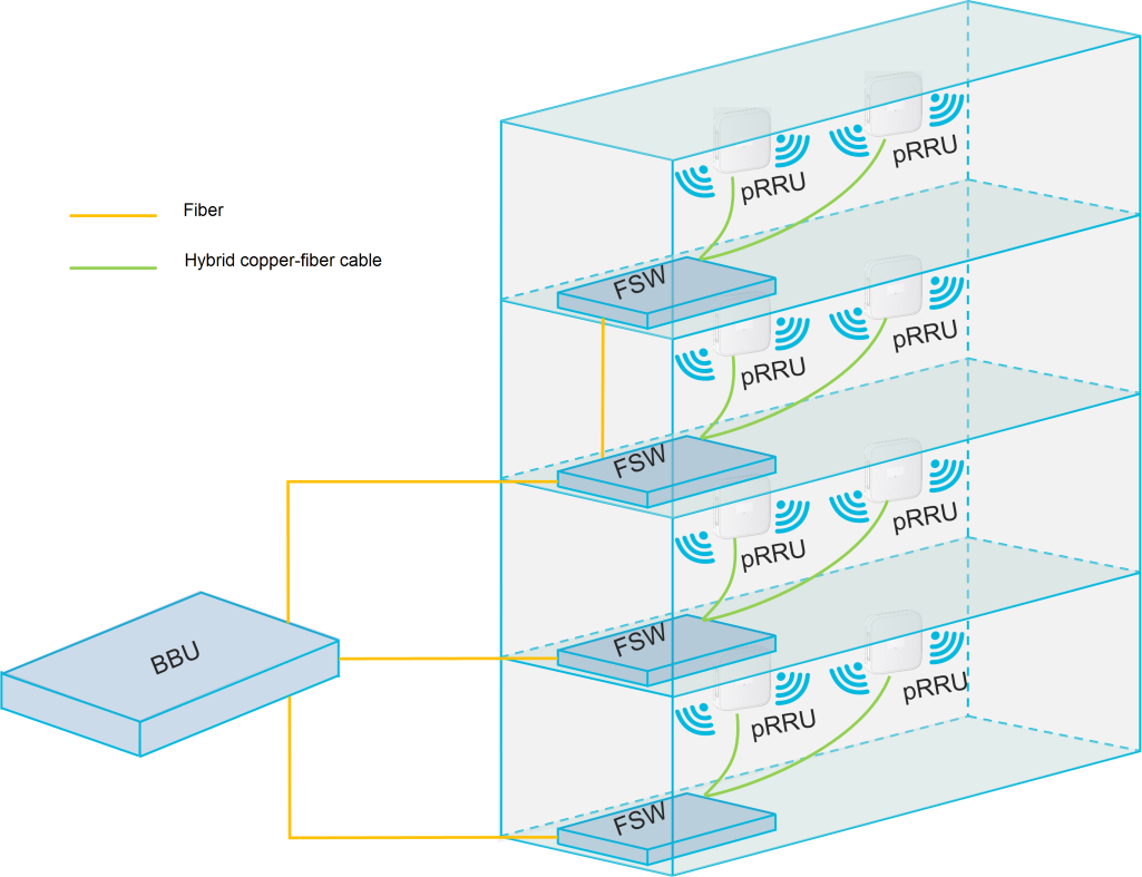
An H3C 5G extended pico station is an indoor distributed wireless access system, featuring simple architecture, ease of deployment, low maintenance, and deep multi-standard coverage. As shown in Figure1-1, an H3C extended pico station contains three parts:
· BBU—Baseband processing unit for the 5G extended pico station, providing device management, configuration management, performance monitoring, clock management, signaling processing, baseband resource management, and wireless resource management.
· FSW—Extension unit of the 5G extended pico station. It connects to the BBU or subordinate FSW through fiber and accesses the pRRU through a hybrid copper-fiber cable to provide power.
· pRRU—Radio frequency remote unit for the 5G extended pico station, providing the following features:
¡ The transmit channel receives digital signals from the BBU enhanced Common Public Radio Interface (eCPRI) port, performs digital-to-analog conversion, frequency modulation, and amplification filtering, and ultimately transmits the RF signal through the antenna.
¡ The receive channel captures the RF signal from the antenna, amplifies and filters it, performs frequency modulation, converts it to a digital signal, and sends it back to the BBU through the eCPRI port.
The pRRU can be directly connected to the BBU or extended through the FSW to expand the cell scale.
Figure1-1 H3C 5G extended pico station
Hardware specifications
Product view
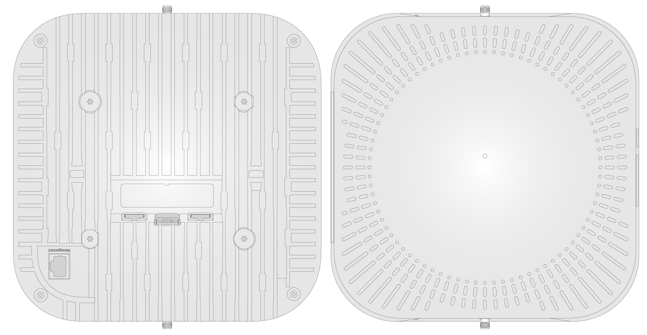
The H3C pRRU5314 can be differentiated by appearance into models with built-in antennas and those with external antennas. As shown in Figure1-2 and Figure1-3, compared to the built-in antenna model, the external antenna model features additional external antenna ports (this manual introduces the model with 2 external antenna ports as an example).
Figure1-2 Product view (without external antenna ports)
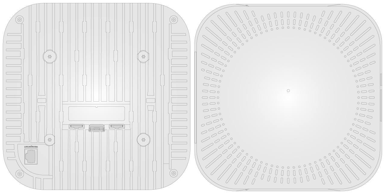
Figure1-3 Product view (with external antenna ports)
As shown in Figure1-4, the pRRU5314 supports multiple external interfaces, and different sub-models may support different interfaces. This manual takes the external antenna model as an example to introduce all interfaces and LEDs. For the specific interfaces supported by different sub-models, see "Hardware specifications."
Figure1-4 pRRU5314 ports and LEDs
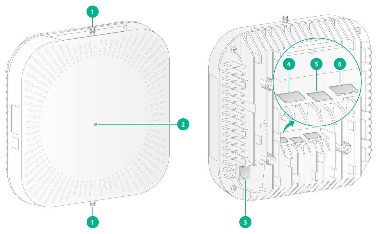
|
1: External antenna port |
2: LED |
|
3: Management port |
4: PoE+/GE port |
|
5: SFP+ port |
6: PoE++ port |
|
|
NOTE: ④ The corresponding network port (PoE++ interface) is the power receiving port for the device, ⑥ and the corresponding network port (PoE+/GE interface) is used to provide power to downstream devices. |
Hardware specifications
Overview of the main specifications
|
|
NOTE: The H3C pRRU can be differentiated into various models by their suffixes, where: · E: Indicates that the pRRU supports a downlink port. · M: Indicates that the pRRU supports three-point antenna deployment. · O: Indicates that the pRRU supports both a downlink port and external antennas. · P: Indicates that the pRRU is a high-power pRRU. |
The H3C pRRU5314 is a dual-mode NR and LTE remote radio unit for picocells, used in conjunction with the picocell main host BBU and the expansion unit FSW to form a complete 5G small cell solution. The H3C pRRU5314 has multiple sub-models, as shown in Table1-1, each supporting different hardware features to accommodate various application scenarios.
Table1-1 Hardware feature differences between the pRRU5314 sub-models
|
Model |
Standard |
Frequency bands |
Downlink port |
Three-point positioning |
External antenna |
High power |
|
pRRU5314-H1 |
NR (TDD)+LTE (FDD) |
N41+B3 |
Not supported |
Not supported |
Not supported |
Not supported |
|
pRRU5314-H1(E) |
NR (TDD)+LTE (FDD) |
N41+B3 |
Supported |
Not supported |
Not supported |
Not supported |
|
pRRU5314-H3 |
NR (TDD)+LTE (FDD) |
N78+B3 |
Not supported |
Not supported |
Not supported |
Not supported |
|
pRRU5314-H3(PE) |
NR (TDD)+LTE (FDD) |
N78+B3 |
Supported |
Not supported |
Not supported |
Supported |
|
pRRU5314-H3(PO) |
NR (TDD)+LTE (FDD) |
N78+B3 |
Supported |
Not supported |
Supported |
Supported |
pRRU5314-H1 hardware specifications
The hardware specifications of pRRU5314-H1 are as shown in Table1-2.
Table1-2 pRRU5314-H1 hardware specifications
|
Specification |
||
|
Dimensions (H × W × D) |
200mm × 200mm × 58mm |
|
|
Weight |
≤ 2kg |
|
|
System power consumption |
≤ 34W |
|
|
Standard |
NR (TDD)+LTE (FDD) |
|
|
Frequency bands |
NR: N41 LTE: B3 |
|
|
Frequency range (MHz) |
NR: 2515MHz to 2675MHz LTE UL: 1710MHz to 1735MHz LTE DL: 1805MHz to 1830MHz |
|
|
Ports |
One fiber port (SFP+ port) One PoE port (PoE++ port) One management port |
|
|
Transceiver channel |
NR: 2T2R LTE: 2T2R |
|
|
Transmission power |
NR: 2×250mW LTE: 2×125mW |
|
|
Built-in antenna specifications |
Gain (dBi) |
NR: 3 LTE: 3 |
|
Polarization type |
Linear polarization |
|
|
Direction |
Omni-directional |
|
|
Single antenna receive sensitivity |
NR: -94dBm LTE: -101dBm |
|
|
IBW |
NR: 100MHz LTE: 20MHz |
|
|
OBW |
NR: 160MHz LTE: 25MHz |
|
|
Synchronization |
Obtain clock synchronization through BBU or FSW |
|
|
Installation methods |
Ceiling-mounted, wall-mounted, dragon bone, round pole, suspension rod |
|
|
Power supply mode |
PoE power supply: -48V DC |
|
|
Cooling method |
Passive cooling |
|
|
Long reach |
Maximum 200 meters through hybrid copper-fiber cable and expansion unit networking |
|
|
Operating temperature (indoor) |
-5°C to 40°C (open environment) -5°C to 55°C (1m/s wind speed scenario) |
|
|
Storage temperature |
-40°C to 70°C |
|
|
Operating humidity (non-condensing) |
5%RH to 95%RH |
|
|
Storage humidity (non-condensing) |
5%RH to 95%RH |
|
|
IP rating |
IP31 |
|
pRRU5314-H1(E) hardware specifications
pRRU5314-H1(E) hardware specifications as shown in Table1-3.
Table1-3 pRRU5314-H1(E) hardware specifications
|
Item |
Specification |
|
|
Dimensions (H × W × D) |
200mm × 200mm × 58mm |
|
|
Weight |
≤ 2kg |
|
|
System power consumption |
≤ 34W |
|
|
Standard |
NR (TDD)+ LTE (FDD) |
|
|
Frequency bands |
NR: N41 LTE: B3 |
|
|
Frequency range (MHz) |
NR: 2515MHz to 2675MHz LTE UL: 1710MHz to 1735MHz LTE DL: 1805MHz to 1830MHz |
|
|
Ports |
One fiber port (SFP+ port) One PoE port (PoE++ port) One management port One downlink network port (PoE+/GE port) |
|
|
Transceiver channel |
NR: 2T2R LTE: 2T2R |
|
|
Transmission power |
NR: 2×200mW LTE: 2×100mW |
|
|
Built-in antenna specifications |
Gain (dBi) |
NR: 3 LTE: 3 |
|
Polarization type |
Linear polarization |
|
|
Direction |
Omni-directional |
|
|
Single antenna receive sensitivity |
NR: -93dBm LTE: -100dBm |
|
|
IBW |
NR: 100MHz LTE: 20MHz |
|
|
OBW |
NR: 160MHz LTE: 25MHz |
|
|
Synchronization |
Obtain clock synchronization through BBU or FSW |
|
|
Installation methods |
Ceiling mount, wall mount, steel beam mount, pole mount, suspension mount |
|
|
Power supply mode |
PoE power supply: -48V DC |
|
|
Cooling method |
Passive cooling |
|
|
Long reach |
Maximum 200 meters network expansion through hybrid copper-fiber cable, with expansion units |
|
|
Operating temperature (indoor) |
-5°C to 40°C (open environment) -5°C to 55°C (1m/s wind speed scenario) |
|
|
Storage temperature |
-40°C to 70°C |
|
|
Operating humidity (non-condensing) |
5%RH to 95%RH |
|
|
Storage humidity (non-condensing) |
5%RH to 95%RH |
|
|
IP rating |
IP31 |
|
pRRU5314-H3 hardware specifications
pRRU5314-H3 hardware specifications as shown in Table1-4.
Table1-4 pRRU5314-H3 hardware specifications
|
Model |
pRRU5314-H3 |
|
|
Dimensions (H × W × D) |
200mm × 200mm × 58mm |
|
|
Weight |
≤ 2kg |
|
|
System power consumption |
≤ 34W |
|
|
Standard |
NR (TDD)+ LTE (FDD) |
|
|
Frequency bands |
NR: N78 LTE: B3 |
|
|
Frequency range (MHz) |
NR: 3300MHz to 3600MHz LTE UL: 1735MHz to 1785MHz LTE DL: 1830MHz to 1880MHz |
|
|
Ports |
One fiber port (SFP+ port) One PoE port (PoE++ port) One management port (Management port) |
|
|
Transceiver channel |
NR: 2T2R LTE: 2T2R |
|
|
Transmission power |
NR: 2×250mW LTE: 2×250mW |
|
|
Built-in antenna specifications |
Gain (dBi) |
NR: 5 LTE: 3 |
|
Polarization type |
Linear polarization |
|
|
Direction |
Omni-directional |
|
|
Single antenna receive sensitivity |
NR: -94dBm LTE: -101dBm |
|
|
IBW |
NR: 100MHz LTE: 20MHz |
|
|
OBW |
NR: 300MHz LTE: 50MHz |
|
|
Synchronization |
Obtain clock synchronization through BBU or FSW |
|
|
Installation methods |
Ceiling-mounted, wall-mounted, dragon beam, round pole, hanger |
|
|
Power supply mode |
Power over Ethernet (PoE): -48V DC |
|
|
Cooling method |
Passive cooling |
|
|
Pull long reach (LR) |
Network with expansion unit through hybrid copper-fiber cable, up to 200 meters |
|
|
Operating temperature (indoor) |
-5°C to 40°C (open environment) -5°C to 55°C (1m/s wind speed scenario) |
|
|
Storage temperature |
-40°C to 70°C |
|
|
Operating humidity (non-condensing) |
5%RH to 95%RH |
|
|
Storage humidity (non-condensing) |
5%RH to 95%RH |
|
|
IP rating |
IP31 |
|
pRRU5314-H3(PE) hardware specifications
pRRU5314-H3(PE) hardware specifications are as shown in Table1-5.
Table1-5 pRRU5314-H3(PE) hardware specifications
|
Model |
pRRU5314-H3(PE) |
|
|
Dimensions (H × W × D) |
200mm × 200mm × 58mm |
|
|
Weight |
≤ 2kg |
|
|
System power consumption |
≤ 34W |
|
|
Standard |
NR (TDD)+ LTE (FDD) |
|
|
Frequency bands |
NR: N78 LTE: B3 |
|
|
Frequency range (MHz) |
NR: 3300MHz to 3600MHz LTE UL: 1735MHz to 1785MHz LTE DL: 1830MHz to 1880MHz |
|
|
Ports |
One fiber port (SFP+ port) One PoE port (PoE++ port) One management port (Management port) One downlink network port (PoE+/GE port) |
|
|
Transceiver channel |
NR: 2T2R LTE: 2T2R |
|
|
Transmission power |
NR: 2×500mW LTE: 2×250mW |
|
|
Built-in antenna specifications |
Gain (dBi) |
NR: 5 LTE: 3 |
|
Polarization type |
Linear polarization |
|
|
Direction |
Omni-directional |
|
|
Single antenna receive sensitivity |
NR: -94dBm LTE: -101dBm |
|
|
IBW |
NR: 100MHz LTE: 20MHz |
|
|
OBW |
NR: 300MHz LTE: 50MHz |
|
|
Synchronization |
Obtain clock synchronization through BBU or FSW |
|
|
Installation methods |
Ceiling-mounted, wall-mounted, purlin-mounted, round-pole-mounted, suspension rod-mounted |
|
|
Power supply mode |
PoE power supply: -48V DC |
|
|
Cooling method |
Passive cooling |
|
|
Long reach |
Network with expansion units through hybrid copper-fiber cable, up to a maximum of 200 meters |
|
|
Operating temperature (indoor) |
-5°C to 40°C (open environment) -5°C to 55°C (1m/s wind speed scenario) |
|
|
Storage temperature |
-40°C to 70°C |
|
|
Operating humidity (non-condensing) |
5%RH to 95%RH |
|
|
Storage humidity (non-condensing) |
5%RH to 95%RH |
|
|
IP rating |
IP31 |
|
pRRU5314-H3(PO) hardware specifications
pRRU5314-H3(PO) hardware specifications are as shown in Table1-6.
Table1-6 pRRU5314-H3(PO) hardware specifications
|
Model |
pRRU5314-H3(PO) |
|
Dimensions (H × W × D) |
200mm × 200mm × 58mm |
|
Weight |
≤ 2kg |
|
System power consumption |
≤ 34W |
|
Standard |
NR (TDD)+ LTE (FDD) |
|
Frequency bands |
NR: N78 LTE: B3 |
|
Frequency range (MHz) |
NR: 3300MHz to 3600MHz LTE UL: 1735MHz to 1785MHz LTE DL: 1830MHz to 1880MHz |
|
Ports |
One fiber port (SFP+ port) One PoE port (PoE++ port) One management port (Management port) One downlink network port (PoE+/GE port) Two external antenna ports (SMA female) |
|
Transceiver channel |
NR: 2T2R LTE: 2T2R |
|
Transmission power |
NR: 2×400mW LTE: 2×200mW |
|
Single antenna receive sensitivity |
NR: -93dBm LTE: -100dBm |
|
IBW |
NR: 100MHz LTE: 20MHz |
|
OBW |
NR: 300MHz LTE: 50MHz |
|
Synchronization |
Obtain clock synchronization through BBU or FSW |
|
Installation methods |
Ceiling mount, wall mount, pole mount, round pole mount, suspension |
|
Power supply mode |
PoE power supply: -48V DC |
|
Cooling method |
Passive cooling |
|
Long reach |
Network with expansion tuple through hybrid copper-fiber cable, up to 200 meters |
|
Operating temperature (indoor) |
-5°C to 40°C (open environment) -5°C to 55°C (1m/s wind speed scenario) |
|
Storage temperature |
-40°C to 70°C |
|
Operating humidity (non-condensing) |
5%RH to 95%RH |
|
Storage humidity (non-condensing) |
5%RH to 95%RH |
|
IP rating |
IP31 |
Ports
SFP+ port
Table1-7 SFP+ port attributes
|
Item |
Description |
|
Connector type |
SFP female connector |
|
Speed |
9.8 Gbps |
|
Compliant standards |
SFP+, eCPRI |
|
Supported services |
Used to connect FSW, transmit eCPRI data |
PoE++ port
Table1-8 PoE++ port attributes
|
Item |
Description |
|
Connector type |
RJ-45 |
|
Compliant standards |
IEEE 802.3bt |
|
Supported services |
Used to connect to FSW, from FSW power supply |
PoE+/GE port
Table1-9 PoE+/GE port attributes
|
Max transmission distance |
100m |
|
Cable specifications |
Category-5 or above twisted pair cable |
|
Supported services |
Used to connect AP, short reach IoT, UWB, Bluetooth devices, etc., supporting the following services: · Supports 1 Gbps/100 Mbps bandwidth data forwarding (DF) · Supports PoE 802.3 at power supply · Supports cascading devices to provide data transmission and power supply for cascading devices |
Management port
Table1-10 Management port attributes
|
Item |
Description |
|
Connector type |
RJ-45 |
|
Port attribute |
Serial port: 9600bps |
|
Compliant standards |
RS232 |
|
Supported services |
Used as a management port for device maintenance and debugging (for internal testing only) |
External antenna port
Table1-11 External antenna port attributes
|
Item |
Description |
|
Connector type |
SMA female connector |
|
Supported services |
Used to connect external antennas that support the frequency bands for pRRU |
Supported transceiver modules
Transceiver module, fiber connector, and fiber appearances
When pRRU is connected to FSW, it needs to be used with SFP+ optical transceiver module, using fiber with LC type fiber connector.
Figure1-5 SFP+ transceiver module
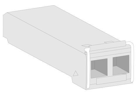
Figure1-6 Fiber with LC-type connector
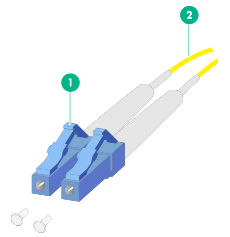
|
1: LC fiber connector |
2: Fiber |
Transceiver module specifications
Table1-12 Transceiver module attributes (1)
|
Product code |
Central wavelength (nm) |
Fiber mode |
Fiber diameter (µm) |
Mode bandwidth (MHz*km) |
Transmission distance |
Transmission Rate |
|
SFP-XG-CPRI-IR-SM1310 |
1310 |
SMF |
9/125 |
- |
1.4km |
4.92 to 10.31Gbps |
Table1-13 Transceiver module attributes (2)
|
Model |
Port Index (dBm) |
|
|
Tx optical power |
Rx optical power |
|
|
SFP-XG-CPRI-IR-SM1310 |
–8.2 to 0.5 |
–14.4 to 0.5 |
LEDs
The LED description of pRRU5314 is shown in Table1-14.
|
LED |
LED color |
LED status |
Description |
|
|
N/A |
Off |
The device is not powered on. |
|
Yellow |
Steady on |
The device is powered on and application programs do not start, or device initialization is abnormal. |
|
|
Flashes twice every one second |
After the device starts, the optical port link is down, or the device is faulty |
||
|
Green |
Steady on |
All cells are in an inactive state |
|
|
Flashes once every two seconds |
All or some cells are in an active state |
||
|
Flashes four times every one second |
Device updates software version |
||
|
Blue |
Flashes twice every one second |
Receive/transmit optical power of the optical link or transceiver module is abnormal |
|
|
Flashes once every two seconds |
Antenna is not online |
Hybrid copper-fiber cables
About hybrid copper-fiber cables
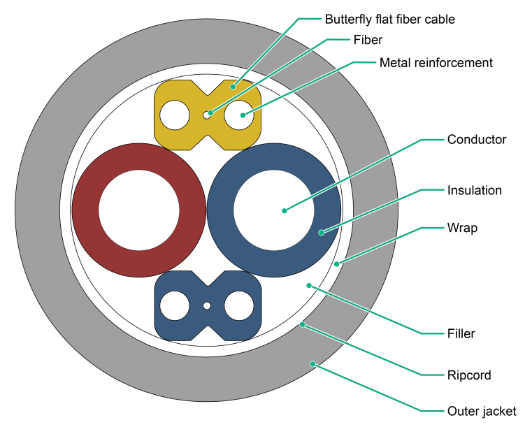
Hybrid copper-fiber cable is a type of fiber cable and electrical cable twisted together. It adds insulated conductors to the fiber cable structure, integrating fiber cable and power copper wires into one, providing longer transmission distances, and suitable for various types of operations.
Figure1-7 Structure of a hybrid copper-fiber cable
Hybrid copper-fiber cable specifications
Specifications overview
Hybrid copper-fiber cable requires the purchase of bare wire, RJ-45 power connector, and LC fiber connector for on-site wiring. Detailed information on bare wire and connectors is shown in Table1-15.
Table1-15 Bare wires and connectors
|
Type |
Description |
Fiber/connector type |
Product code |
|
RJ-45 power connector |
Network interface connector-single row-1 port-2PIN-plug-4mm-UPOE-non-integrated transformer |
RJ-45 |
1408A047 |
|
Bare wire |
Symmetrical twisted pair cable-hybrid copper-fiber cable-4 cores-100 meters |
Single-mode, G.657A2 |
HYBRID CABLE-100 |
|
Bare wire |
Symmetrical twisted pair cable-hybrid copper-fiber cable-4 cores-200 meters |
Single-mode, G.657A2 |
HYBRID CABLE-200 |
|
Bare wire |
Symmetrical twisted pair cable-hybrid copper-fiber cable-4 cores-500 meters |
Single-mode, G.657A2 |
HYBRID CABLE-500 |
|
LC fiber connector |
Fiber connector-LC/PC-LC/PC-single-mode-2mm-3m |
LC |
OP-LC/PC-LC/PC-3-S |
Introduction to RJ-45 Power Connector
The appearance of the power connector of RJ-45 with product code 1408A047 is shown in Figure1-1.Figure1-8
Figure1-8 Appearance of RJ-45 type power connector (1408A047)
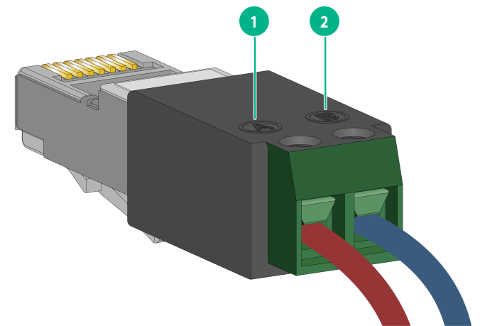
|
1: Positive electrode |
2: Negative electrode |
Assembling a hybrid copper-fiber cable
|
|
IMPORTANT: · Assembly of hybrid copper-fiber cable must be carried out by personnel with experience in optical communication construction, and equipped with professional fiber assembly and testing tools. · When using the optical transceiver module with product code SFP-XG-CPRI-IR-SM1310, please ensure that the optical link attenuation between FSW and pRRU is less than 6.2dB. · Please take protective measures such as dust and pressure prevention for the assembled hybrid copper-fiber cable. · When assembling LC fiber connectors using fusion splicing, please install a protective fiber box on the fusion sleeve to protect it from being pulled or bent, thus avoiding damage. |
Removing the outer jacket of the hybrid copper-fiber cable
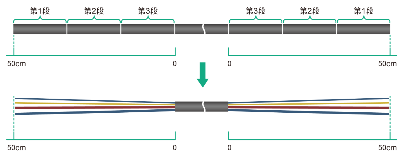
Strip the outer jacket of the hybrid copper-fiber cable at both ends, with a length of 50cm. To facilitate the stripping of the outer jacket and prevent accidental fiber breakage, it is recommended to strip it in 2 to 3 segments.
|
|
IMPORTANT: · Do not damage the power cord (PWR) core wire and the Optical fiber core. · Do not forcefully bend the hybrid copper-fiber cable or peel off the outer jacket. · In order to facilitate on-site cable hiding, you can increase the stripping length appropriately. |
Figure1-9 Removing the outer jacket
Assembling LC-type fiber connector
1. Use a butterfly-shaped fiber stripper to strip the fiber sheath, with a length of 5cm.
Figure1-10 Strip fiber sheath

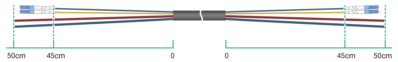
2. Install the optical fiber core wire to the LC fiber connector by cold or fusion splicing. The fiber length shown in Figure1-11. can be used as a reference length for cold splicing. If using fusion splicing to assemble the LC fiber connector, please make appropriate adjustments according to the length of the fiber to be spliced and the on-site environment.
Figure1-11 Connect LC fiber connector
3. Test the assembled fiber to ensure it is functioning properly.
Assembling the RJ-45 power connector (product code 1408A047)
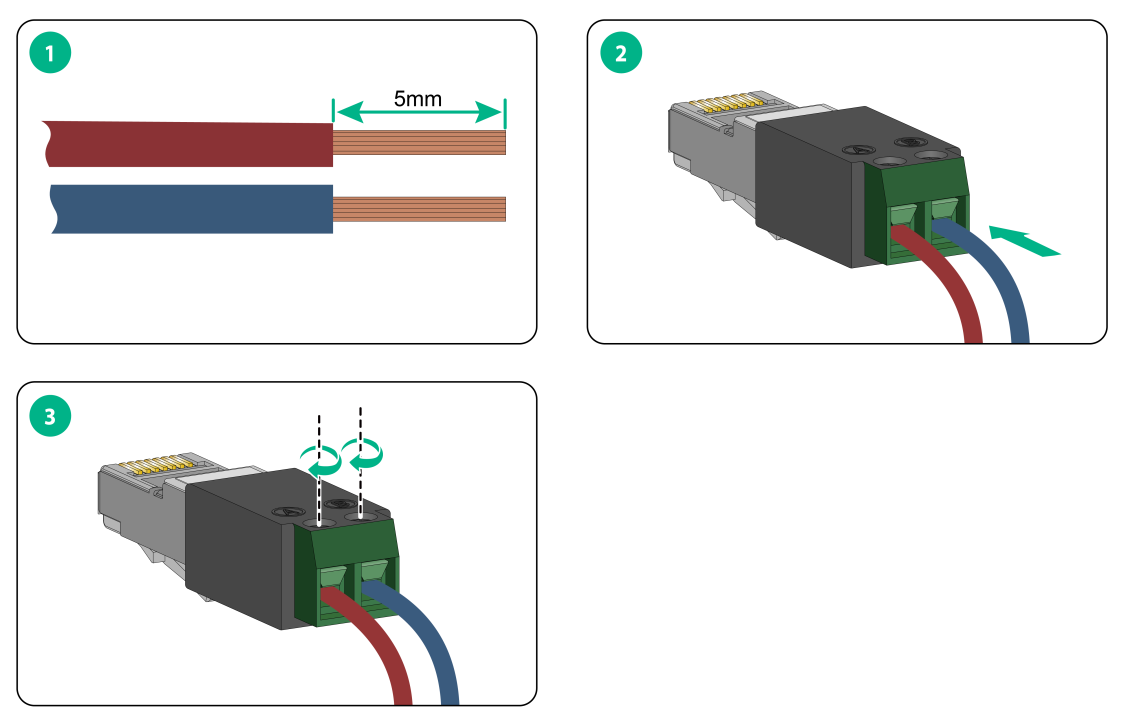
1. Trim the power cord at the rear of the LC fiber connector, with the trimmed length less than 8mm, as shown in Figure1-12.
Figure1-12 Cut
the power c ord
(PWR)
ord
(PWR)
2. As shown in Figure1-13, connect the power cord to the RJ-45 type power connector, the specific steps are as follows: Figure1-13
a. Peel off the insulation layer of the power cord wire, the length of the peeling is 5mm.
b. Insert the two power cord (PWR) cores into the bottom of the power connector cable access hole, ensuring that the copper wire is not bent or exposed. Note that the positive (A) and negative (B) identify (ID) on the connector, and the positive and negative ends of the same power cord core need to be consistent.
c. Tighten the connection with a screwdriver to prevent the power cord (PWR) from coming loose.
Figure1-13 Connecting the RJ-45 type power connector
3. Pull the power cord outward with force. If the power connector does not come off, then the power cord is connected properly.
Figure1-14 Testing the RJ-45 type power connector

Ethernet twisted pair cable
Introduction
An Ethernet twisted pair cable consists of four pairs of insulated copper wires twisted together. Every wire uses a different color, and has a diameter of about 1 mm (0.04 in). A pair of twisted copper cables can cancel the electromagnetic radiation of each other, and reduce interference of external sources. An Ethernet twisted pair cable mainly transmits analog signals and is advantageous in transmitting data over shorter distances. It is the commonly used transmission media of the Ethernet. The maximum transmission distance of the Ethernet twisted pair cable is 100 m (328.08 ft). To extend the transmission distance, you can connect two twisted pair cable segments with a repeater. At most four repeaters can be added, which means five segments can be joined together to provide a transmission distance of 500 m (1640.42 ft).
Ethernet twisted pair cables can be classified into category 3, category 4, category 5, category 5e, category 6, and category 7 cables based on performance. In LANs, category 5, category 5e, and category 6 are commonly used.
Table1-16 Description for commonly used Ethernet twisted pair cables
|
Type |
Description |
|
Category 5 |
Suitable for data transmission at a maximum speed of 100 Mbps |
|
Category 5e |
Suitable for data transmission at a maximum speed of 1000 Mbps |
|
Category 6 |
Suitable for data transmission at a speed higher than 1 Gbps |
Based on whether a metal shielding is used, Ethernet twisted pair cables can be classified into shielded twisted pair (STP) and unshielded twisted pair (UTP). An STP cable provides a metallic braid between the twisted pairs and the outer jacket. This metallic braid helps reduce radiation, prevent information from being listened, and eliminate external electromagnetic interference (EMI) of external sources. STPs have strict application requirements and are expensive although they provide better EMI prevention performance than UTPs, so in most LANs, UTPs are commonly used.
An Ethernet twisted pair cable connects network devices through the RJ-45 connectors at the two ends. Figure1-15 shows the pinouts of an RJ-45 connector.
Figure1-15 RJ-45 connector pinout

|
|
NOTE: To power the pRRU through an Ethernet twisted pair cable, make sure the Ethernet cable is a Category 5e or above cable. |
EIA/TIA cabling specifications define two standards, 568A and 568B, for cable pinouts.
· Standard 568A—pin 1: white/green stripe, pin 2: green solid, pin 3: white/orange stripe, pin 4: blue solid, pin 5: white/blue stripe, pin 6: orange solid, pin 7: white/brown stripe, pin 8: brown solid.
· Standard 568B—pin 1: white/orange stripe, pin 2: orange solid, pin 3: white/green stripe, pin 4: blue solid, pin 5: white/blue stripe, pin 6: green solid, pin 7: white/brown stripe, pin 8: brown solid.
Ethernet twisted pair cables can be classified into straight-through and crossover cables based on their pinouts.
· Straight-through—The pinouts at both ends are T568B compliant, as shown in Figure1-16.
· Crossover—The pinouts are T568B compliant at one end and T568A compliant at the other end, as shown in Figure1-17.
Figure1-16 Straight-through cable


Select an Ethernet twisted pair cable according to the RJ-45 Ethernet port type on your device. An RJ-45 Ethernet port can be MDI (for routers and PCs) or MDIX (for switches). Table1-17 and Table1-18 show their pinouts.
Table1-17 RJ-45 MDI port pinouts
|
Pin |
10BASE-T/100BASE-TX |
1000BASE-T |
||
|
Signal |
Function |
Signal |
Function |
|
|
1 |
Tx+ |
Sends data |
BIDA+ |
Bi-directional data cable A+ |
|
2 |
Tx- |
Sends data |
BIDA- |
Bi-directional data cable A- |
|
3 |
Rx+ |
Receives data |
BIDB+ |
Bi-directional data cable B+ |
|
4 |
Reserved |
N/A |
BIDC+ |
Bi-directional data cable C+ |
|
5 |
Reserved |
N/A |
BIDC- |
Bi-directional data cable C- |
|
6 |
Rx- |
Receives data |
BIDB- |
Bi-directional data cable B- |
|
7 |
Reserved |
N/A |
BIDD+ |
Bi-directional data cable D+ |
|
8 |
Reserved |
N/A |
BIDD- |
Bi-directional data cable D- |
Table1-18 RJ-45 MDIX port pinouts
|
Pin |
10BASE-T/100BASE-TX |
1000BASE-T |
||
|
Signal |
Function |
Signal |
Function |
|
|
1 |
Rx+ |
Receives data |
BIDB+ |
Bi-directional data cable B+ |
|
2 |
Rx- |
Receives data |
BIDB- |
Bi-directional data cable B- |
|
3 |
Tx+ |
Sends data |
BIDA+ |
Bi-directional data cable A+ |
|
4 |
Reserved |
N/A |
BIDD+ |
Bi-directional data cable D+ |
|
5 |
Reserved |
N/A |
BIDD- |
Bi-directional data cable D- |
|
6 |
Tx- |
Sends data |
BIDA- |
Bi-directional data cable A- |
|
7 |
Reserved |
N/A |
BIDC+ |
Bi-directional data cable C+ |
|
8 |
Reserved |
N/A |
BIDC- |
Bi-directional data cable C- |
To ensure normal communication, the pins for sending data on one port must correspond to the pins for receiving data on the peer port. When both of the ports on the two devices are MDI or MDIX, use a crossover Ethernet cable; when one port is MDI and the other is MDIX, use a straight-through Ethernet cable. To summarize, straight-through and crossover cables connect the following devices:
· Straight-through cables connect devices of different types—for example, router to PC and router to switch.
· Crossover cables connect devices of the same type—for example, switch to switch, router to router, and PC to PC.
If an RJ-45 Ethernet port is enabled with MDI/MDIX autosensing, it can automatically negotiate pin roles.
|
|
NOTE: The RJ-45 Ethernet ports on the device support MDI/MDIX autosensing. |
Making an Ethernet twisted pair cable
1. Cut the cable to a required length with the crimping tool.
2. Strip off an appropriate length of the cable sheath. The length is typically that of the RJ-45 connector.
3. Untwist the pairs so that they can lay flat, and arrange the colored wires based on the wiring specifications.
4. Cut the top of the wires even with one another. Insert the wires into the RJ-45 connector and make sure the wires extend to the front of the RJ-45 connector and make good contact with the metal contacts in the RJ-45 connector and in the correct order.
5. Crimp the RJ-45 connector with the crimping tool until you hear a click.
6. Use a cable tester to verify the connectivity of the cable.
Power injectors
About power injectors
The EWPAM1UPOE2 is a two-port power injector with a broad operating temperature range and enhanced protective capabilities. It is suitable for both indoor and outdoor environments (additional waterproofing measures are required for outdoor use). It connects to network terminal devices via Category 5e cabling and supports 10/100/1000M network environments.
Figure1-18 Power injector view

|
(1) Wall mount hole |
(2) Power input cable |
Figure1-19 Panel view
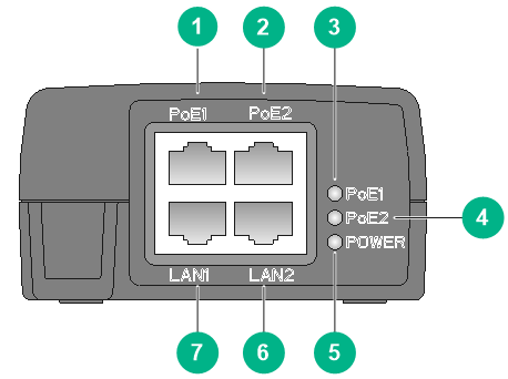
|
(1) PoE1 port |
(2) PoE2 port |
(3) PoE1 LED |
|
(4) PoE2 LED |
(5) POWER LED |
(6) LAN2 port |
|
(7) LAN1 port |
||
Table1-19 Product specifications
|
Item |
Specification |
|
Dimensions (W × D × H) |
213mm x 85mm x 46mm |
|
Weight |
0.5Kg |
|
Rated input voltage |
100V AC to 240V AC, 50/60Hz |
|
Maximum input current |
1.5A (115V AC, full load) 0.75A (230V AC, full load) |
|
Rated output current |
1.1A |
|
Total output power |
≤ 60W |
|
Temperature |
Operating: -30°C to +55°C Storage: -30°C to +70°C |
|
Humidity (non-condensing) |
Operating: 5%RH to 95%RH Storage: 10%RH to 90%RH |
|
Safety certification |
CCC |
Panel LEDs
Table1-20 LED description
|
LED |
Mark |
Status |
Description |
|
PoE1 LED |
PoE1 |
Off |
PoE1 port output with no load |
|
Steady green |
PoE1 port is supplying power correctly |
||
|
PoE2 LED |
PoE2 |
Off |
PoE2 port output with no load |
|
Steady green |
PoE2 port is supplying power correctly |
||
|
POWER LED |
POWER |
Off |
The power injector is not powered on |
|
Steady green |
The power injector is running correctly |
Acronyms
|
Acronym |
Full name |
|
BBU |
Baseband Unit |
|
eCPRI |
enhanced Common Public Radio Interface |
|
FSW |
Front Haul Switch |
|
IBW |
Instantaneous BandWidth |
|
LTE |
Long Term Evolution |
|
MMF |
Multi-Mode Fiber |
|
NR |
New Radio Access |
|
OBW |
Operation Bandwidth |
|
pRRU |
Pico RRU |
|
RRU |
Remote Radio Unit |
|
SFP |
Small Form-factor Pluggable |
|
SMF |
Single Mode Fiber |