- Table of Contents
- Related Documents
-
| Title | Size | Download |
|---|---|---|
| 02-Layer 2 forwarding configuration | 222.25 KB |
Configuring normal Layer 2 forwarding
About normal Layer 2 forwarding
Display and maintenance commands for Layer 2 forwarding
Configuring fast Layer 2 forwarding
Disabling VLAN ID check for fast Layer 2 forwarding
Display and maintenance commands for fast Layer 2 forwarding
Configuring cut-through Layer 2 forwarding
About cut-through Layer 2 forwarding
Restrictions: Hardware compatibility with cut-through Layer 2 forwarding
Restrictions and guidelines for cut-through Layer 2 forwarding configuration
Configuring bridging forwarding
Configuring inter-VLAN bridge forwarding
Configuring security service bypass
Display and maintenance commands for bridge forwarding
Configuring fast bridge forwarding
Disabling VLAN ID check for fast bridge forwarding
Display and maintenance commands for fast bridge forwarding
Configuring normal Layer 2 forwarding
About normal Layer 2 forwarding
When an incoming frame's destination MAC address does not match any Layer 3 interface's MAC address, normal Layer 2 forwarding forwards the frame through a Layer 2 interface.
The device uses the destination MAC address of the frame to look for a match in the MAC address table.
· The device forwards the frame out of the outgoing interface in the matching entry if a match is found.
· The device floods the frame to all interfaces in the VLAN of the frame if no match is found.
Normal Layer 2 forwarding is enabled by default.
Display and maintenance commands for Layer 2 forwarding
Execute display commands in any view and reset commands in user view.
|
Task |
Command |
|
Display Layer 2 forwarding statistics. |
display mac-forwarding statistics [ interface interface-type interface-number ] |
|
Clear Layer 2 forwarding statistics. |
reset mac-forwarding statistics |
Configuring fast Layer 2 forwarding
About fast Layer 2 forwarding
Fast Layer 2 forwarding improves packet forwarding efficiency by using a high-speed cache and flow-based technology. It identifies a flow by using the following items:
· Source IP address.
· Source port number.
· Destination IP address.
· Destination port number.
· Protocol number.
· Input interface.
· Output interface.
· VLAN ID.
Fast Layer 2 forwarding creates an entry in a high-speed cache by obtaining the forwarding information of a flow's first packet. Subsequent packets of the flow are forwarded based on the entry.
Fast Layer 2 forwarding is enabled by default.
Disabling VLAN ID check for fast Layer 2 forwarding
About this task
The VLAN ID of a packet helps the device to determine the TCP session to which the packet belongs. On a hot backup system formed by two firewalls, you must disable VLAN ID check if the traffic incoming interfaces on the primary and secondary devices belong to different VLANs. If you enable VLAN ID check, traffic cannot match session entries correctly when asymmetric-path traffic exists.
Procedure
1. Enter system view.
system-view
2. Disable VLAN ID check for fast Layer 2 forwarding.
undo mac fast-forwarding check-vlan-id
By default, VLAN ID check is enabled for fast Layer 2 forwarding.
Display and maintenance commands for fast Layer 2 forwarding
Execute display commands in any view.
|
Task |
Command |
|
Display IPv4 fast forwarding entries. |
display mac-forwarding cache ip [ ip-address ] [ slot slot-number ] |
|
Display IPv4 fast forwarding entries for fragments. |
display mac-forwarding cache ip fragment [ ip-address ] [ slot slot-number ] |
|
Display IPv6 fast forwarding entries. |
display mac-forwarding cache ipv6 [ ipv6-address ] [ slot slot-number ] |
Configuring cut-through Layer 2 forwarding
About cut-through Layer 2 forwarding
A cut-through forwarding-enabled device forwards a frame after it receives the first 64 bytes of the frame. This feature reduces the transmission time of a frame and enhances forwarding performance.
Restrictions: Hardware compatibility with cut-through Layer 2 forwarding
|
Series |
Models |
Cut-through Layer 2 forwarding compatibility |
|
F50X0 series |
F5010, F5020, F5020-GM, F5040, F5000-C, F5000-S |
No |
|
F5030, F5030-6GW, F5060, F5080, F5000-A, F5000-M |
Yes |
|
|
F5000-CN series |
F5000-CN30, F5000-CN60 |
No |
|
F5000-AI series |
F5000-AI-15, F5000-AI-20, F5000-AI-40 |
Yes |
|
F5000-V series |
F5000-V30 |
Yes |
|
F1000-AI series |
F1000-AI-10, F1000-AI-15, F1000-AI-60, F1000-AI-65, F1000-AI-70, F1000-AI-75, F1000-AI-80, F1000-AI-90 |
No |
|
F1000-AI-05, F1000-AI-20, F1000-AI-25, F1000-AI-30, F1000-AI-35, F1000-AI-50, F1000-AI-55 |
Yes |
|
|
F1000-L series |
F1003-L, F1005-L, F1010-L |
Yes |
|
F10X0 series |
F1005, F1010, F1090 |
Yes |
|
F1020, F1020-GM, F1030, F1030-GM, F1050, F1060, F1070, F1070-GM, F1070-GM-L, F1080 |
No |
|
|
F1000-V series |
F1000-V50, F1000-V70 |
No |
|
F1000-V60, F1000-V90 |
Yes |
|
|
F1000-SASE series |
F1000-SASE100 |
Yes |
|
F1000-SASE200 |
No |
|
|
F1000-AK series |
F1000-AK130, F1000-AK135, F1000-AK140, F1000-AK145, F1000-AK150, F1000-AK155, F1000-AK160, F1000-AK165, F1000-AK170, F1000-AK175, F1000-AK180, F1000-AK185, F1000-GM-AK370, F1000-GM-AK380, F1000-AK711, F1000-AK1010, F1000-AK1020, F1000-AK1030, F1000-AK1110, F1000-AK1120, F1000-AK1130, F1000-AK1140, F1000-AK1212, F1000-AK1222, F1000-AK1242, F1000-AK1252, F1000-AK1262, F1000-AK1272, F1000-AK1232, F1000-AK1312, F1000-AK1322, F1000-AK1332 |
No |
|
F1000-AK108, F1000-AK109, F1000-AK110, F1000-AK115, F1000-AK120, F1000-AK125, F1000-AK710, F1000-AK1150, F1000-AK1160, F1000-AK1170, F1000-AK1180, F1000-AK1342, F1000-AK1352, F1000-AK1362, F1000-AK1414, F1000-AK1424, F1000-AK1434, F1000-AK1514, F1000-AK1524, F1000-AK1534, F1000-AK1614, F1000-AK9110, F1000-AK9210 |
Yes |
|
|
Firewall modules |
IM-NGFWX-IV, LSPM6FWD, LSPM6FWDB, LSQM1FWDSC0, LSQM2FWDSC0, LSU3FWCEA0, LSUM1FWCEAB0, LSUM1FWDEC0, LSWM1FWD0, LSX1FWCEA1, LSXM1FWDF1 |
No |
|
vFW series |
vFW1000, vFW2000 |
No |
Restrictions and guidelines for cut-through Layer 2 forwarding configuration
With cut-through forwarding, the device forwards CRC-error frames because it starts forwarding frames before their CRC field is received.
Procedure
1. Enter system view.
system-view
2. Enable cut-through forwarding.
cut-through enable
By default, cut-through forwarding is disabled.
Configuring bridge forwarding
About bridge forwarding
Bridge forwarding allows users to customize bridge instances to implement VLAN or port based secure packet forwarding.
Bridge forwarding types
Bridge forwarding has the following types:
· Inter-VLAN bridge forwarding—Forwards a packet between different VLANs.
· Inline forwarding—Inline forwarding has the following types:
¡ Reflect-type bridge forwarding—Forwards a packet through the receiving port of the packet.
¡ Forward-type bridge forwarding—Forwards a packet through a port that is different from the receiving port of the packet.
¡ Blackhole-type bridge forwarding—Drops the received packets.
Inter-VLAN bridge forwarding
Inter-VLAN bridge forwarding enables communication between different VLANs at the data link layer. It is typically used on firewall products. A firewall connected to a switch filters Layer 2 traffic before passing the traffic to the switch for further forwarding.
As shown in Figure 1, bridge forwarding enables communication between VLANs 10 and 20. VLANs 10 and 20 are in bridge instance 1 on the firewall. The interface that connects the switch to the firewall is Port C.
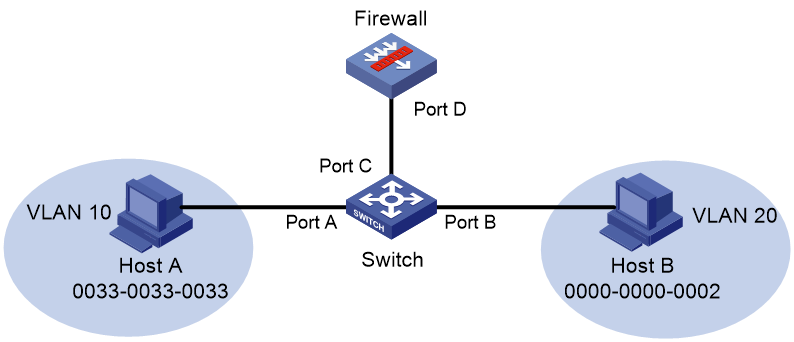
The following process uses ARP to describe the MAC address learning and packet forwarding in bridge forwarding. Host A requires the MAC address of Host B and sends out an ARP request. When receiving the request from Host A, bridge forwarding processes the request as follows:
1. The switch performs the following operations:
a. Learns a new entry to the MAC address table of the switch. The entry contains the MAC address of Host A (0033-0033-0033), the output interface Port A, and VLAN 10.
b. Broadcasts the request in VLAN 10. Because VLAN 10 is in bridge instance 1, the request enters the firewall through Port C.
2. The firewall performs the following operations:
a. Learns a new entry to the MAC address table of bridge instance 1. The entry contains the MAC address of Host A (0033-0033-0033), the output interface Port D, and VLAN 10.
b. Replaces the VLAN tag of the request with VLAN 20 and broadcasts the request in VLAN 20. No matching MAC address entry exists in VLAN 20.
c. Sends the request to the switch through Port D.
3. The switch performs the following operations:
a. Learns a new entry to the MAC address table of the switch. The entry contains the MAC address of Host A (0033-0033-0033), interface Port C, and VLAN 20.
b. Broadcasts the request in VLAN 20.
Host B in VLAN 20 receives the request, places its MAC address in the reply, and sends the reply to Host A. Bridge forwarding processes the reply as follows:
1. The switch performs the following operations:
a. Learns a new entry to the MAC address table of the switch. The entry contains the MAC address of Host B (0000-0000-0002), the output interface Port B, and VLAN 20.
b. Uses the destination MAC address 0033-0033-0033 and VLAN ID 20 to search the MAC address table for a match. An entry with interface Port C is found.
c. Sends the reply to the firewall through Port C.
2. The firewall performs the following operations:
a. Learns a new entry to the MAC address table of bridge instance 1. The entry contains the MAC address of Host B (0000-0000-0002), the output interface Port D, and VLAN 20.
b. Uses the destination MAC address 0033-0033-0033 to search the MAC address table of bridge instance 1 for a match. An entry with the output interface Port D and VLAN 10 is found.
c. Replaces the VLAN ID of the reply (VLAN 20) with the VLAN ID in the entry (VLAN 10).
d. Sends the reply to the switch through Port D.
3. The switch performs the following operations:
a. Uses the destination MAC address 0033-0033-0033 and VLAN ID 10 to search the MAC address table for a match. An entry with the output interface Port A exists.
b. Forwards the reply through Port A.
Inline forwarding
Inline forwarding monitors traffic at the data link layer. It is typically used on security devices. Layer 2 traffic arriving at a device is redirected to a security device based on QoS policies, filtered, and then forwarded toward the destination.
Inline forwarding can be further classified into the following forwarding types:
· Reflect-type bridge forwarding.
· Blackhole-type bridge forwarding.
· Forward-type bridge forwarding.
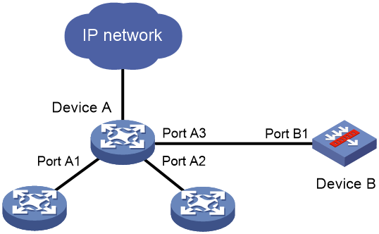
Reflect-type/blackhole-type bridge forwarding
Reflect-type bridge forwarding and blackhole-type bridge forwarding are applicable to the scenario where a device directly accesses the network and is directly connected to a security device.
As shown in Figure 2, Device A is connected to the security device (Device B) through a physical port.
· In reflect-type bridge forwarding mode, packets arriving at Device A are forwarded to Device B for security service processing and then sent back to Device A for forwarding.
· In blackhole-type bridge forwarding mode, packets arriving at Device A are forwarded to Device B. Device B processes the packets and then drops the packets.
Figure 2 Reflect-type/blackhole-type bridge forwarding network
Forward-type bridge forwarding
Forward-type bridge forwarding is applicable to the scenario where a device accesses the network through a security device.
As shown in Figure 3, Device A is connected to Device B through two physical ports. Device B uses one port to receive packets from Device A, and it uses the other port to send packets back to Device A.
Figure 3 Forward-type bridge forwarding network
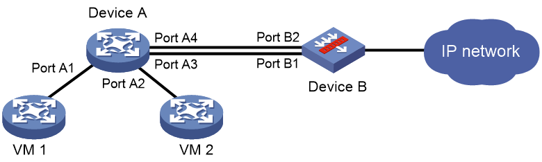
Packet processing example in inline forwarding
As shown in Figure 2 and Figure 3, when VMs 1 and 2 communicate through Device A, inline forwarding processes packets between them as follows:
· Device A forwards the received packets to Device B.
· Device B passes the IP packets to the security modules for processing and sends other types of packets back to Device A.
· Device B creates forwarding entries for IP packets that meet the security requirements and forwards them to Device A. IP packets that do not meet the security requirements are dropped.
Configuring bridging forwarding
Configuring inter-VLAN bridge forwarding
1. Enter system view.
system-view
2. (Optional.) Set the aging timer for dynamic MAC address entries.
bridge mac-address timer aging seconds
The default setting is 300 seconds.
3. Create an inter-VLAN bridge instance, and enter bridge view.
bridge bridge-index inter-vlan
4. Add a list of VLANs to the bridge instance.
add vlan vlan-id-list
5. (Optional.) Set the MAC learning limit on the bridge instance.
mac-address max-mac-count count
By default, a maximum of 4096 MAC addresses can be learned on a bridge instance.
Configuring inline forwarding
Restrictions and guidelines
You can manually create reflect-type, forward-type, and blackhole-type bridge instances for inline forwarding and add interfaces to the instances.
The device will automatically create a forward-type bridge instance upon insertion of a hardware bypass subcard. For a forward-type bridge instance to be automatically created, make sure the device does not have an inter-VLAN bridge instance before you insert a hardware bypass subcard.
If you configure inline forwarding on a security device connected to a switch, disable MAC address learning on the switch's interface that is connected to the security device to avoid frequent MAC moves.
Only one interface can be added to a reflect-type or blackhole-type bridge instance.
Only two interfaces can be added to a manually created forward-type bridge instance. The two interfaces must be the same type.
An automatically created forward-type bridge instance uses the pair of interfaces on the bypass subcard by default and you cannot edit the interfaces in the instance.
Procedure
1. Enter system view.
system-view
2. (Optional.) Configure the device to ignore the tunnel encapsulation when forwarding tunneled packets in inline mode.
bridge tunnel-encapsulation skip
In inline forwarding mode, tunneled packets are forwarded based on information in the tunnel encapsulation by default.
3. Create a bridge instance and enter its view.
¡ Create a reflect-type bridge instance.
bridge bridge-index reflect
¡ Create a forward-type bridge instance.
bridge bridge-index forward
¡ Create a blackhole-type bridge instance.
bridge bridge-index blackhole
4. Add an interface to the bridge instance.
add interface interface-type interface-number
By default, no interfaces exist in a manually created bridge instance.
Configuring security service bypass
About this task
By default, packets are processed by the security service first before being forwarded according to the configured bridge forwarding mode.
The security service bypass feature enables user traffic to bypass security service processing of a security device and be forwarded directly according to the configured bridge forwarding mode.
The following security service bypass modes are supported:
· Internal bypass—User traffic is sent to the security device but is not processed by it. The security device directly forwards or drops the traffic according to the configured bridge forwarding mode.
· External bypass—User traffic is forwarded by the Power Free Connector (PFC) device directly without passing through the security device.
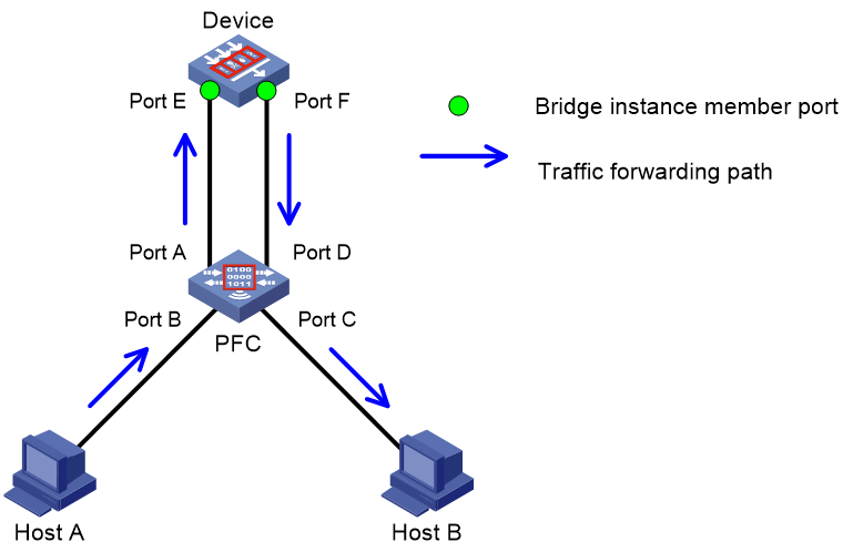
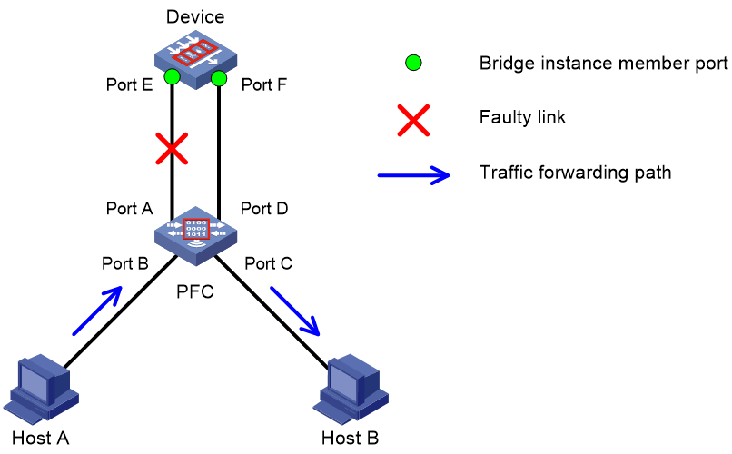
As shown in Figure 4:
· Host A needs to communicate with Host B.
· On the security device, Port E and Port F are added to a forward-type bridge instance. Security service bypass is disabled.
Traffic is forwarded in the normal forwarding path when the links between the security device and the PFC are operating correctly.
Figure 4 Normal traffic forwarding path
If a link goes down, you can enable external bypass on the security device. Traffic from Host A will be forwarded to Host B directly by the PFC, as shown in Figure 5.
Figure 5 Traffic forwarding path when a link goes down
External bypass can be further classified in to the following types:
· Static external bypass—External bypass takes effect immediately when configured and must be manually disabled.
· Dynamic external bypass—External bypass is enabled or disabled automatically based on the status of the links between the security device and the PFC. The security device polls the link status periodically and enables external bypass if one or both links go down. External bypass is disabled automatically if the failed links come up.
Restrictions and guidelines for security service bypass
If you configure the bypass enable command and the bypass enable external command for the same bridge instance multiple times, the most recent configuration takes effect.
External bypass is not supported in multi-chassis IRF systems.
External bypass is available only in the default context. The following guidelines apply when you configure external bypass in the default context that contains a Layer 2 Ethernet interface assigned to it in shared-mode:
· If external bypass takes effect, user traffic will be forwarded by the PFC. On the Layer 2 Ethernet interface, settings of a non-default context that conflict with the external bypass feature do not take effect.
· If external bypass does not take effect, user traffic will not be forwarded by the PFC. On the Layer 2 Ethernet interface, settings of a non-default context that conflict with the external bypass feature take effect, and user traffic will be forwarded accordingly.
For a forward-type bridge instance that is automatically created upon insertion of a hardware bypass subcard, you can enable only internal bypass for the instance.
You can enable external bypass only for one manually created forward-type bridge instance. The interfaces added to the forward-type bridge instance must reside on the same slot.
This feature and the interface collaboration feature cannot be used at the same time. For more information about the interface collaboration feature, see High Availability Configuration Guide.
Enabling internal security service bypass
1. Enter system view.
system-view
2. Enter bridge instance view.
¡ Enter the view of a reflect-type bridge instance.
bridge bridge-index reflect
¡ Enter the view of an automatically created forward-type bridge instance.
bridge bridge-index forward
¡ Enter the view of a manually created forward-type bridge instance.
bridge bridge-index forward
¡ Enter the view of a blackhole-type bridge instance.
bridge bridge-index blackhole
3. Enable internal security service bypass.
bypass enable
Security service bypass is disabled by default.
Enabling external security service bypass
1. Enter system view.
system-view
2. Enter the view of a manually created forward-type bridge instance.
bridge bridge-index forward
3. Enable external security service bypass.
bypass enable external [ auto [ check-interval interval ] ]
Security service bypass is disabled by default.
Support for this command depends on the device model. For more information, see the command reference.
Display and maintenance commands for bridge forwarding
|
|
IMPORTANT: Support for the display bridge bypass status command depends on the device model. For more information, see the command reference. |
Execute display commands in any view.
|
Task |
Command |
|
Display MAC address entries in bridge instances. |
display bridge mac-address [ bridge-index [ vlan vlan-id ] ] [ count ] [ slot slot-number ] |
|
Display the status of the security service bypass feature. |
display bridge bridge-id bypass status |
Configuring fast bridge forwarding
About fast bridge forwarding
Fast bridge forwarding improves packet forwarding efficiency by using a high-speed cache and flow-based technology. It identifies a flow by using the following items:
· Source IP address.
· Source port number.
· Destination IP address.
· Destination port number.
· Protocol number.
· Input interface.
· Output interface.
· VLAN ID.
Fast bridge forwarding creates an entry in a high-speed cache by obtaining the forwarding information of a flow's first packet. Subsequent packets of the flow are forwarded based on the entry.
Fast bridge forwarding is enabled by default.
Disabling VLAN ID check for fast bridge forwarding
About this task
The VLAN ID of a packet helps the device to determine the TCP session to which the packet belongs. On a hot backup system formed by two firewalls, you must disable VLAN ID check if the traffic incoming interfaces on the primary and secondary devices belong to different VLANs. If you enable VLAN ID check, traffic cannot match session entries correctly when asymmetric-path traffic exists.
Restrictions and guidelines
Only inline forwarding supports VLAN ID check. You do not need to configure this feature for inter-VLAN fast bridge forwarding because the device does not check VLAN IDs for inter-VLAN fast bridge forwarding. That is, this feature does not take effect on inter-VLAN fast bridge forwarding.
On a hot backup system formed by two firewalls, inter-VLAN fast bridge forwarding enables a packet to match the same session after being transmitted between the primary and secondary devices.
Procedure
1. Enter system view.
system-view
2. Disable VLAN ID check for fast bridge forwarding.
undo bridge fast-forwarding check-vlan-id
By default, VLAN ID check is enabled for fast bridge forwarding.
Display and maintenance commands for fast bridge forwarding
Execute display commands in any view.
|
Task |
Command |
|
Display IPv4 fast bridge forwarding entries. |
display bridge cache ip { inline | inter-vlan } [ ip-address ] [ slot slot-number ] |
|
Display IPv4 fast bridge forwarding entries for fragments. |
display bridge cache ip fragment { inline | inter-vlan } [ ip-address ] [ slot slot-number ] |
|
Display IPv6 fast bridge forwarding entries. |
display bridge cache ipv6 { inline | inter-vlan } [ ipv6-address ] [ slot slot-number ] |