- Table of Contents
-
- 05-Layer 3—IP Services Configuration Guide
- 00-Preface
- 01-ARP configuration
- 02-IP addressing configuration
- 03-DNS configuration
- 04-mDNS relay configuration
- 05-IP forwarding basics configuration
- 06-Fast forwarding configuration
- 07-Adjacency table configuration
- 08-IRDP configuration
- 09-IP performance optimization configuration
- 10-UDP helper configuration
- 11-IPv6 basics configuration
- 12-IPv6 fast forwarding configuration
- 13-AFT configuration
- 14-Tunneling configuration
- 15-GRE configuration
- 16-HTTP redirect configuration
- Related Documents
-
| Title | Size | Download |
|---|---|---|
| 11-IPv6 basics configuration | 656.48 KB |
Configuring basic IPv6 settings
Configuring an IPv6 global unicast address
About IPv6 global unicast address
Generating an EUI-64 IPv6 address
Manually assigning an IPv6 global unicast address
Stateless address autoconfiguration
Configuring prefix-specific address autoconfiguration
Configuring an IPv6 link-local address
Configuring automatic generation of an IPv6 link-local address for an interface
Manually assigning an IPv6 link-local address to an interface
Configuring an IPv6 anycast address
Configuring path MTU discovery
Setting the interface MTU for IPv6 packets
Setting a static path MTU for an IPv6 address
Setting the aging time for dynamic path MTUs
Controlling ICMPv6 message sending and receiving
Disabling receiving a specific type of ICMPv6 messages
Disabling sending a specific type of ICMPv6 messages
Configuring the rate limit for ICMPv6 error messages
Enabling replying to multicast echo requests
Enabling sending ICMPv6 destination unreachable messages
Enabling sending ICMPv6 time exceeded messages
Enabling sending ICMPv6 redirect messages
Specifying the source address for ICMPv6 packets
Setting the forwarding priority value for ICMPv6 echo replies in hardware
Enabling IPv6 local fragment reassembly
Configuring IPv6 bandwidth-based load sharing
Disabling processing the source route option
Enabling Layer 3 packet statistics collection
Specifying the maximum number of IPv6 FIB entries on an interface module
Display and maintenance commands for IPv6 basics
Basic IPv6 settings configuration examples
Example: Configuring basic IPv6 settings
Configuring IPv6 neighbor discovery
ICMPv6 messages used by IPv6 neighbor discovery
Neighbor reachability detection
Router/prefix discovery and stateless address autoconfiguration
IPv6 neighbor discovery tasks at a glance
Configuring a static neighbor entry
Setting the dynamic neighbor learning limit
Enabling unsolicited NA learning
Enabling learning ND information from a different subnet
Enabling learning ND information from a different subnet globally
Enabling learning ND information from a different subnet on an interface
Setting the aging timer for ND entries in stale state
Minimizing link-local ND entries
Configuring RA message sending and parameters
Enabling the sending of RA messages
Configuring parameters for RA messages
Specifying DNS server information in RA messages
Specifying DNS suffix information in RA messages
Suppressing advertising DNS information in RA messages
Setting the maximum number of attempts to send an NS message for DAD
Enabling duplicate detection for duplicate addresses
Configuring IPv6 ND direct route advertisement
About IPv6 ND direct route advertisement
Application in Layer 3 access networks
Application in L2VPN access to L3VPN networks
Enabling recording user IPv6 address conflicts
Enabling recording ND entry learning events
Enabling recording IP address conflicts between the local device and endpoints
Enabling recording overspeed events of ND Miss message generation and ND packet sending
Display and maintenance commands for IPv6 ND
Configuring basic IPv6 settings
About IPv6
IPv6, also called IP next generation (IPng), was designed by the IETF as the successor to IPv4. One significant difference between IPv6 and IPv4 is that IPv6 increases the IP address size from 32 bits to 128 bits.
IPv6 features
Simplified header format
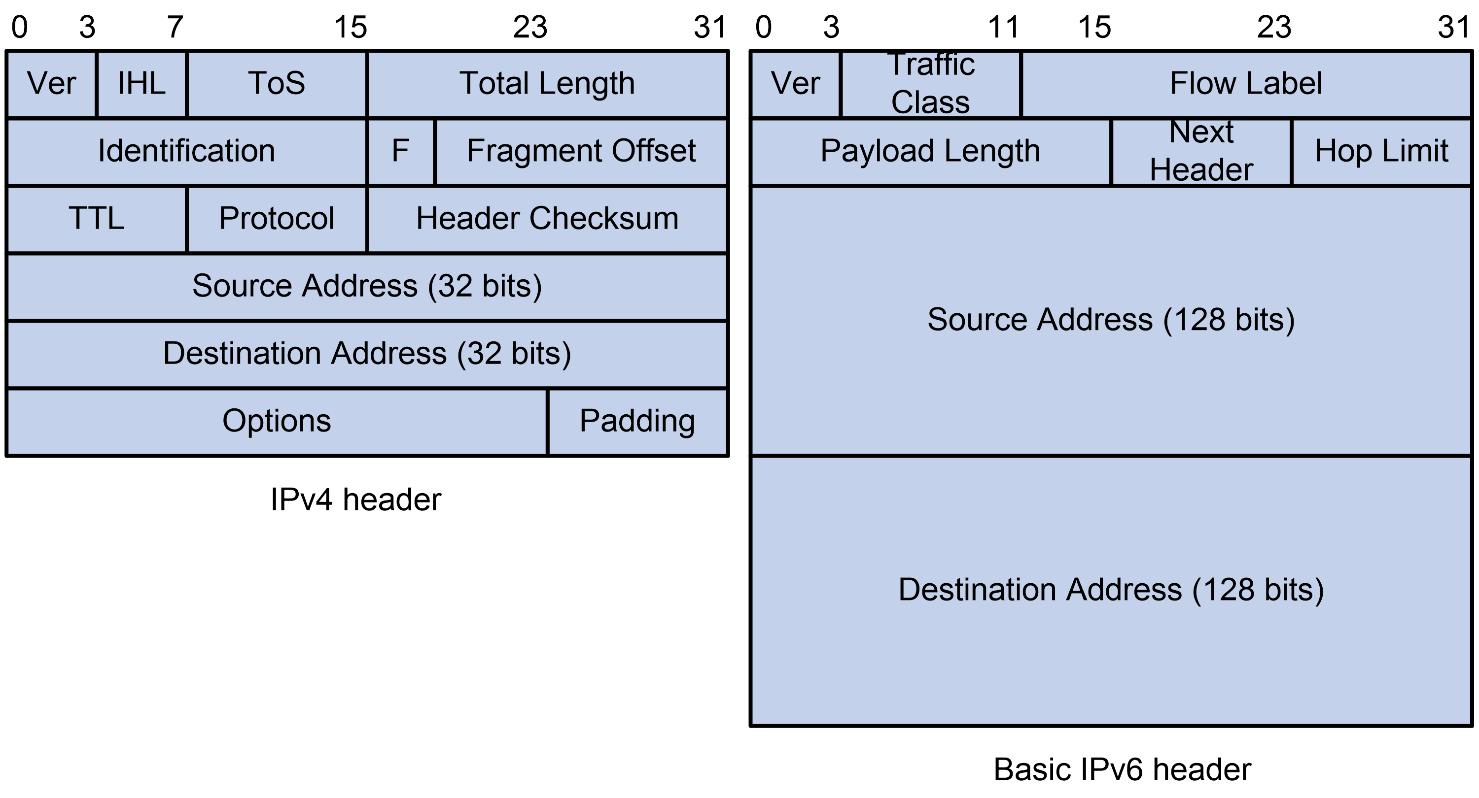
IPv6 removes several IPv4 header fields or moves them to the IPv6 extension headers to reduce the length of the basic IPv6 packet header. The basic IPv6 packet header has a fixed length of 40 bytes to simplify IPv6 packet handling and improve forwarding efficiency. Although the IPv6 address size is four times the IPv4 address size, the basic IPv6 packet header size is only twice the size of the option-less IPv4 packet header.
Figure 1 IPv4 packet header format and basic IPv6 packet header format
Larger address space
IPv6 can provide 3.4 x 1038 addresses to meet the requirements of hierarchical address assignment for both public and private networks.
Hierarchical address structure
IPv6 uses a hierarchical address structure to speed up route lookup and reduce the IPv6 routing table size through route aggregation.
Address autoconfiguration
To simplify host configuration, IPv6 supports stateful and stateless address autoconfiguration.
· Stateful address autoconfiguration enables a host to acquire an IPv6 address and other configuration information from a server (for example, a DHCPv6 server). For more information about DHCPv6 server, see DHCPv6 configuration in BRAS Services Configuration Guide.
· Stateless address autoconfiguration enables a host to automatically generate an IPv6 address and other configuration information by using its link-layer address and the prefix information advertised by a router.
To communicate with other hosts on the same link, a host automatically generates a link-local address based on its link-layer address and the link-local address prefix (FE80::/10).
Built-in security
IPv6 defines extension headers to support IPsec. IPsec provides end-to-end security and enhances interoperability among different IPv6 applications.
QoS support
The Flow Label field in the IPv6 header allows the device to label the packets of a specific flow for special handling.
Enhanced neighbor discovery mechanism
The IPv6 neighbor discovery protocol uses a group of ICMPv6 messages to manage information exchange among neighboring nodes on the same link. The group of ICMPv6 messages replaces ARP messages, ICMPv4 router discovery messages, and ICMPv4 redirect messages and provides a series of other functions.
Flexible extension headers
IPv6 eliminates the Options field in the header and introduces optional extension headers to provide scalability and improve efficiency. The Options field in the IPv4 packet header contains a maximum of 40 bytes, whereas the IPv6 extension headers are restricted to the maximum size of IPv6 packets.
IPv6 addresses
IPv6 address format
An IPv6 address is represented as a set of 16-bit hexadecimals separated by colons (:). An IPv6 address is divided into eight groups, and each 16-bit group is represented by four hexadecimal numbers, for example, 2001:0000:130F:0000:0000:09C0:876A:130B.
To simplify the representation of IPv6 addresses, you can handle zeros in IPv6 addresses by using the following methods:
· The leading zeros in each group can be removed. For example, the above address can be represented in a shorter format as 2001:0:130F:0:0:9C0:876A:130B.
· If an IPv6 address contains one or more consecutive groups of zeros, they can be replaced by a double colon (::). For example, the above address can be represented in the shortest format as 2001:0:130F::9C0:876A:130B.
|
|
IMPORTANT: A double colon can appear once or not at all in an IPv6 address. This limit allows the device to determine how many zeros the double colon represents and correctly convert it to zeros to restore a 128-bit IPv6 address. |
An IPv6 address consists of an address prefix and an interface ID, which are equivalent to the network ID and the host ID of an IPv4 address.
An IPv6 address prefix is written in IPv6-address/prefix-length notation. The prefix-length is a decimal number indicating how many leftmost bits of the IPv6 address are in the address prefix.
IPv6 address types
IPv6 addresses include the following types:
· Unicast address—An identifier for a single interface, similar to an IPv4 unicast address. A packet sent to a unicast address is delivered to the interface identified by that address.
· Multicast address—An identifier for a set of interfaces (typically belonging to different nodes), similar to an IPv4 multicast address. A packet sent to a multicast address is delivered to all interfaces identified by that address.
Broadcast addresses are replaced by multicast addresses in IPv6.
· Anycast address—An identifier for a set of interfaces (typically belonging to different nodes). A packet sent to an anycast address is delivered to the nearest interface among the interfaces identified by that address. The nearest interface is chosen according to the routing protocol's measure of distance.
The type of an IPv6 address is designated by the first several bits, called the format prefix.
Table 1 Mappings between address types and format prefixes
|
Type |
Format prefix (binary) |
IPv6 prefix ID |
|
|
Unicast address |
Unspecified address |
00...0 (128 bits) |
::/128 |
|
Loopback address |
00...1 (128 bits) |
::1/128 |
|
|
Link-local address |
1111111010 |
FE80::/10 |
|
|
Global unicast address |
Other forms |
N/A |
|
|
Multicast address |
11111111 |
FF00::/8 |
|
|
Anycast address |
Anycast addresses use the unicast address space and have the identical structure of unicast addresses. |
||
Unicast addresses
Unicast addresses include global unicast addresses, link-local unicast addresses, the loopback address, and the unspecified address.
· Global unicast addresses—Equivalent to public IPv4 addresses, global unicast addresses are provided for Internet service providers. This type of address allows for prefix aggregation to restrict the number of global routing entries.
· Link-local addresses—Used for communication among link-local nodes for neighbor discovery and stateless autoconfiguration. Packets with link-local source or destination addresses are not forwarded to other links.
· A loopback address—0:0:0:0:0:0:0:1 (or ::1). It has the same function as the loopback address in IPv4. It cannot be assigned to any physical interface. A node uses this address to send an IPv6 packet to itself.
· An unspecified address—0:0:0:0:0:0:0:0 (or ::). It cannot be assigned to any node. Before acquiring a valid IPv6 address, a node fills this address in the source address field of IPv6 packets. The unspecified address cannot be used as a destination IPv6 address.
Multicast addresses
IPv6 multicast addresses listed in Table 2 are reserved for special purposes.
Table 2 Reserved IPv6 multicast addresses
|
Address |
Application |
|
FF01::1 |
Node-local scope all-nodes multicast address. |
|
FF02::1 |
Link-local scope all-nodes multicast address. |
|
FF01::2 |
Node-local scope all-routers multicast address. |
|
FF02::2 |
Link-local scope all-routers multicast address. |
Multicast addresses also include solicited-node addresses. A node uses a solicited-node multicast address to acquire the link-layer address of a neighboring node on the same link and to detect duplicate addresses. Each IPv6 unicast or anycast address has a corresponding solicited-node address. The format of a solicited-node multicast address is FF02:0:0:0:0:1:FFXX:XXXX. FF02:0:0:0:0:1:FF is fixed and consists of 104 bits, and XX:XXXX is the last 24 bits of an IPv6 unicast address or anycast address.
EUI-64 address-based interface identifiers
An interface identifier is 64 bits long and uniquely identifies an interface on a link. Interfaces generate EUI-64 address-based interface identifiers differently.
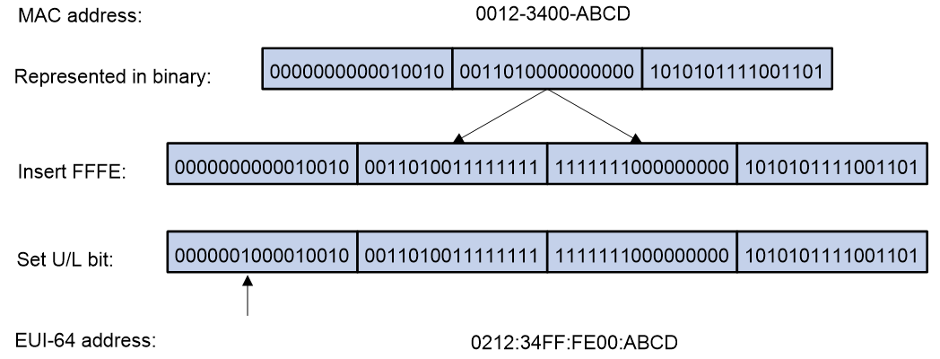
· On an IEEE 802 interface (such as an Ethernet interface and a VLAN interface)—The interface identifier is derived from the link-layer address (typically a MAC address) of the interface. The MAC address is 48 bits long.
To obtain an EUI-64 address-based interface identifier, follow these steps:
a. Insert the 16-bit binary number 1111111111111110 (hexadecimal value of FFFE) behind the 24th high-order bit of the MAC address.
b. Invert the universal/local (U/L) bit (the seventh high-order bit). This operation makes the interface identifier have the same local or global significance as the MAC address.
Figure 2 Converting a MAC address into an EUI-64 address-based interface identifier
· On a tunnel interface—The lower 32 bits of the EUI-64 address-based interface identifier are the source IPv4 address of the tunnel interface. The higher 32 bits of the EUI-64 address-based interface identifier of an ISATAP tunnel interface are 0000:5EFE, whereas those of other tunnel interfaces are all zeros. For more information about tunnels, see tunneling configuration in Layer 3—IP Services Configuration Guide.
· On an interface of another type (such as a serial interface)—The EUI-64 address-based interface identifier is generated randomly by the device.
IPv6 path MTU discovery
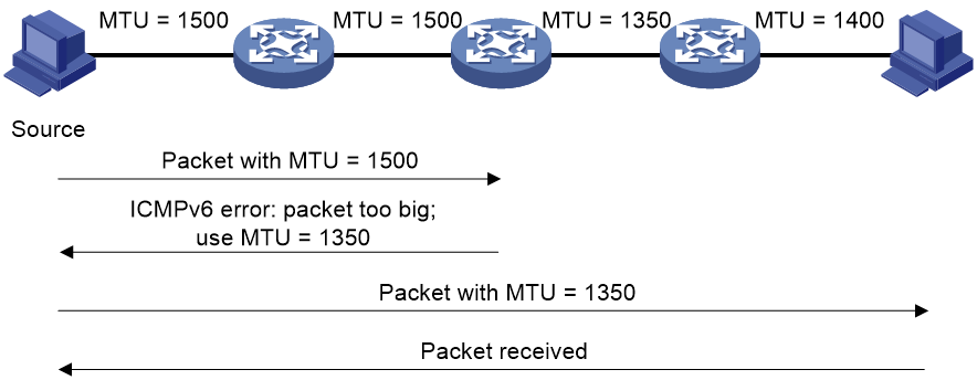
The links that a packet passes from a source to a destination can have different MTUs, among which the minimum MTU is the path MTU. If a packet exceeds the path MTU, the source end fragments the packet to reduce the processing pressure on intermediate devices and to use network resources effectively.
A source end uses path MTU discovery to find the path MTU to a destination, as shown in Figure 3.
1. The source host sends a packet no larger than its MTU to the destination host.
2. If the MTU of an intermediate device's output interface is smaller than the packet, the device performs the following operations:
¡ Discards the packet.
¡ Returns an ICMPv6 error message containing the interface MTU to the source host.
3. Upon receiving the ICMPv6 error message, the source host performs the following operations:
¡ Uses the returned MTU to limit the packet size.
¡ Performs fragmentation.
¡ Sends the fragments to the destination host.
4. Step 2 and step 3 are repeated until the destination host receives the packet. In this way, the source host finds the minimum MTU of all links in the path to the destination host.
Figure 3 Path MTU discovery process
IPv6 transition technologies
IPv6 transition technologies enable communication between IPv4 and IPv6 networks. The following IPv6 transition technologies can be used for different applications:
· Dual stack (RFC 2893)
· Tunneling (RFC 2893)
· AFT
· IPv6 on the provider edge routers (6PE)
Dual stack
Dual stack is the most direct transition approach. A network node that supports both IPv4 and IPv6 is a dual-stack node. A dual-stack node configured with an IPv4 address and an IPv6 address can forward both IPv4 and IPv6 packets. An application that supports both IPv4 and IPv6 prefers IPv6 at the network layer.
Dual stack is suitable for communication between IPv4 nodes or between IPv6 nodes. It is the basis of all transition technologies. However, it does not solve the IPv4 address depletion issue because each dual-stack node must have a globally unique IPv4 address.
Tunneling
Tunneling uses one network protocol to encapsulate the packets of another network protocol and transfers them over the network. For more information about tunneling, see tunneling configuration in Layer 3—IP Services Configuration Guide.
AFT
AFT translates an IP address of one address family into an IP address of the other address family, enabling an IPv4 network and an IPv6 network to communicate with each other. Configured on the edge devices of the IPv4 and IPv6 networks, AFT is transparent to users and does not require configuration changes on IPv4 hosts and IPv6 hosts. For more information about AFT, see AFT configuration in Layer 3—IP Services Configuration Guide.
6PE
6PE enables communication between isolated IPv6 networks over an IPv4 backbone network.
6PE adds labels to the IPv6 routing information about customer networks and advertises the information into the IPv4 backbone network over internal Border Gateway Protocol (IBGP) sessions. IPv6 packets are labeled and forwarded over tunnels on the backbone network. The tunnels can be GRE tunnels or MPLS LSPs.
Figure 4 Network diagram
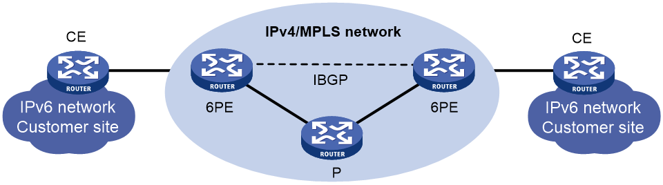
6PE is a highly efficient solution. When an ISP wants to utilize the existing IPv4/MPLS network to provide IPv6 traffic switching, it only needs to upgrade the PE routers. In addition, the operation risk of 6PE is very low.
For more information about 6PE, see BGP configuration in Layer 3—IP Routing Configuration Guide.
Protocols and standards
· RFC 1881, IPv6 Address Allocation Management
· RFC 1887, An Architecture for IPv6 Unicast Address Allocation
· RFC 1981, Path MTU Discovery for IP version 6
· RFC 2375, IPv6 Multicast Address Assignments
· RFC 2460, Internet Protocol, Version 6 (IPv6) Specification
· RFC 2464, Transmission of IPv6 Packets over Ethernet Networks
· RFC 2526, Reserved IPv6 Subnet Anycast Addresses
· RFC 3307, Allocation Guidelines for IPv6 Multicast Addresses
· RFC 4191, Default Router Preferences and More-Specific Routes
· RFC 4291, IP Version 6 Addressing Architecture
· RFC 4443, Internet Control Message Protocol (ICMPv6) for the Internet Protocol Version 6 (IPv6) Specification
· RFC 4862, IPv6 Stateless Address Autoconfiguration
IPv6 basics tasks at a glance
To configure basic IPv6 settings, perform the following tasks:
1. Configuring an IPv6 address
Choose the following tasks as needed:
¡ Configuring an IPv6 global unicast address
¡ Configuring an IPv6 link-local address
¡ Configuring an IPv6 anycast address
2. (Optional.) Configuring path MTU discovery
¡ Setting the interface MTU for IPv6 packets
¡ Setting a static path MTU for an IPv6 address
¡ Setting the aging time for dynamic path MTUs
3. (Optional.) Controlling ICMPv6 message sending and receiving
¡ Disabling receiving a specific type of ICMPv6 messages
¡ Disabling sending a specific type of ICMPv6 messages
¡ Configuring the rate limit for ICMPv6 error messages
¡ Enabling replying to multicast echo requests
¡ Enabling sending ICMPv6 destination unreachable messages
¡ Enabling sending ICMPv6 time exceeded messages
¡ Enabling sending ICMPv6 redirect messages
¡ Specifying the source address for ICMPv6 packets
¡ Setting the forwarding priority value for ICMPv6 echo replies in hardware
4. (Optional.) Enabling router renumbering
5. (Optional.) Enabling IPv6 local fragment reassembly
6. (Optional.) Configuring IPv6 bandwidth-based load sharing
7. (Optional.) Disabling processing the source route option
8. (Optional.) Enabling Layer 3 packet statistics collection
9. (Optional.) Specifying the maximum number of IPv6 FIB entries on an interface module
Configuring an IPv6 global unicast address
About IPv6 global unicast address
Use one of the following methods to configure an IPv6 global unicast address for an interface:
· EUI-64 IPv6 address—The IPv6 address prefix of the interface is manually configured, and the interface ID is generated automatically by the interface.
· Manual configuration—The IPv6 global unicast address is manually configured.
· Stateless address autoconfiguration—The IPv6 global unicast address is generated automatically based on the address prefix information contained in the RA message.
· Prefix-specific address autoconfiguration—The IPv6 global unicast address is generated automatically based on the prefix specified by its ID. The prefix can be manually configured or obtained through DHCPv6.
You can configure multiple IPv6 global unicast addresses on an interface.
Manually configured global unicast addresses (including EUI-64 IPv6 addresses) take precedence over automatically generated ones. If you manually configure a global unicast address with the same address prefix as an existing global unicast address on an interface, the manually configured one takes effect. However, it does not overwrite the automatically generated address. If you delete the manually configured global unicast address, the device uses the automatically generated one.
Generating an EUI-64 IPv6 address
1. Enter system view.
system-view
2. Enter interface view.
interface interface-type interface-number
3. Configure an EUI-64 IPv6 address on the interface.
ipv6 address { ipv6-address prefix-length | ipv6-address/prefix-length } eui-64
By default, no EUI-64 IPv6 address is configured on an interface.
Manually assigning an IPv6 global unicast address
1. Enter system view.
system-view
2. Enter interface view.
interface interface-type interface-number
3. Assign an IPv6 global unicast address to the interface.
ipv6 address { ipv6-address prefix-length | ipv6-address/prefix-length }
By default, no IPv6 global unicast address is configured on an interface.
Stateless address autoconfiguration
About this task
Stateless address autoconfiguration enables an interface to automatically generate an IPv6 global unicast address by using the address prefix in the received RA message and the interface ID. On an IEEE 802 interface (such as an Ethernet interface or a VLAN interface), the interface ID is generated based on the interface's MAC address and is globally unique. An attacker can exploit this rule to identify the sending device easily.
To fix the vulnerability, you can configure the temporary address feature. With this feature, an IEEE 802 interface generates the following addresses:
· Public IPv6 address—Includes the address prefix in the RA message and a fixed interface ID generated based on the MAC address of the interface.
· Temporary IPv6 address—Includes the address prefix in the RA message and a random interface ID generated through MD5.
You can also configure the interface to preferentially use the temporary IPv6 address as the source address of sent packets. When the valid lifetime of the temporary IPv6 address expires, the interface deletes the address and generates a new one. This feature enables the system to send packets with different source addresses through the same interface. If the temporary IPv6 address cannot be used because of a DAD conflict, the public IPv6 address is used.
The preferred lifetime and valid lifetime for a temporary IPv6 address are determined as follows:
· The preferred lifetime of a temporary IPv6 address takes the smaller of the following values:
¡ The preferred lifetime of the address prefix in the RA message.
¡ The preferred lifetime configured for temporary IPv6 addresses minus DESYNC_FACTOR (a random number in the range of 0 to 600 seconds).
· The valid lifetime of a temporary IPv6 address takes the smaller of the following values:
¡ The valid lifetime of the address prefix.
¡ The valid lifetime configured for temporary IPv6 addresses.
Restrictions and guidelines
If the IPv6 prefix in the RA message is not 64 bits long, stateless address autoconfiguration fails to generate an IPv6 global unicast address.
To generate a temporary address, an interface must be enabled with stateless address autoconfiguration. Temporary IPv6 addresses do not overwrite public IPv6 addresses, so an interface can have multiple IPv6 addresses with the same address prefix but different interface IDs.
If an interface fails to generate a public IPv6 address because of a prefix conflict or other reasons, it does not generate any temporary IPv6 address.
Executing the undo ipv6 address auto command on an interface deletes all IPv6 global unicast addresses and link-local addresses that are automatically generated on the interface.
Enabling stateless address autoconfiguration
1. Enter system view.
system-view
2. Enter interface view.
interface interface-type interface-number
3. Enable stateless address autoconfiguration on an interface, so that the interface can automatically generate a global unicast address.
ipv6 address auto
By default, the stateless address autoconfiguration feature is disabled on an interface.
Configuring the temporary address feature and preferentially using the temporary IPv6 address as the source address of outgoing packets
1. Enter system view.
system-view
2. Enable the temporary IPv6 address feature.
ipv6 temporary-address [ valid-lifetime preferred-lifetime ]
By default, the temporary IPv6 address feature is disabled.
3. Enable the system to preferentially use the temporary IPv6 address as the source address of the outgoing packets.
ipv6 prefer temporary-address
By default, the system does not preferentially use the temporary IPv6 address as the source address of the outgoing packets.
Configuring prefix-specific address autoconfiguration
1. Enter system view.
system-view
2. Configure an IPv6 prefix.
Choose one option as needed:
¡ Configure a static IPv6 prefix.
ipv6 prefix prefix-number ipv6-prefix/prefix-length
By default, no static IPv6 prefixes exist.
¡ Use DHCPv6 to obtain a dynamic IPv6 prefix.
For more information about IPv6 prefix acquisition, see "Configuring the DHCPv6 client."
3. Enter interface view.
interface interface-type interface-number
4. Specify an IPv6 prefix for an interface to automatically generate an IPv6 global unicast address and advertise the prefix.
ipv6 address prefix-number sub-prefix/prefix-length
By default, no IPv6 prefix is specified for the interface to automatically generate an IPv6 global unicast address.
Configuring an IPv6 link-local address
About IPv6 link-local address
Configure IPv6 link-local addresses using one of the following methods:
· Automatic generation—The device automatically generates a link-local address for an interface according to the link-local address prefix (FE80::/10) and the link-layer address of the interface.
· Manual assignment—Manually configure an IPv6 link-local address for an interface.
Restrictions and guidelines
After you configure an IPv6 global unicast address for an interface, the interface automatically generates a link-local address. This link-local address is the same as the one generated by using the ipv6 address auto link-local command. If a link-local address is manually assigned to an interface, this manual assigned link-local address takes effect. If the manually assigned link-local address is deleted, the automatically generated link-local address takes effect.
Using the undo ipv6 address auto link-local command on an interface deletes only the link-local address generated by the ipv6 address auto link-local command. If the interface has an IPv6 global unicast address, it still has a link-local address. If the interface has no IPv6 global unicast address, it has no link-local address.
An interface can have only one link-local address. As a best practice, use the automatic generation method to avoid link-local address conflicts. If both the automatic generation and manual assignment methods are used, the manual assignment takes precedence.
· If you first use automatic generation and then manual assignment, the manually assigned link-local address overwrites the automatically generated one.
· If you first use manual assignment and then automatic generation, both of the following occur:
¡ The link-local address is still the manually assigned one.
¡ The automatically generated link-local address does not take effect. If you delete the manually assigned address, the automatically generated link-local address takes effect.
Configuring automatic generation of an IPv6 link-local address for an interface
1. Enter system view.
system-view
2. Enter interface view.
interface interface-type interface-number
3. Configure the interface to automatically generate an IPv6 link-local address.
ipv6 address auto link-local
By default, no link-local address is configured on an interface.
After an IPv6 global unicast address is configured on the interface, a link-local address is generated automatically.
Manually assigning an IPv6 link-local address to an interface
1. Enter system view.
system-view
2. Enter interface view.
interface interface-type interface-number
3. Manually assign an IPv6 link-local address to the interface.
ipv6 address ipv6-address link-local
By default, no link-local address is configured on an interface.
Configuring an IPv6 anycast address
1. Enter system view.
system-view
2. Enter interface view.
interface interface-type interface-number
3. Configure an IPv6 anycast address.
ipv6 address { ipv6-address prefix-length | ipv6-address/prefix-length } anycast
By default, no IPv6 anycast address is configured on an interface.
Configuring path MTU discovery
Setting the interface MTU for IPv6 packets
About this task
IPv6 routers do not support packet fragmentation. If a packet exceeds the MTU of the output interface, the router discards the packet and sends a packet too big message to the source host. This message contains the interface MTU. The source host fragments the packet according to the returned MTU. To avoid extra traffic overhead due to packet dropping, set a proper interface MTU.
Procedure
1. Enter system view.
system-view
2. Enter interface view.
interface interface-type interface-number
3. Set the interface MTU for IPv6 packets.
ipv6 mtu size
By default, no interface MTU is set.
Setting a static path MTU for an IPv6 address
About this task
You can set a static path MTU for an IPv6 address. Before sending a packet to the IPv6 address, the device compares the output interface MTU with the static path MTU. If the packet size exceeds the smaller one of the two values, the device fragments the packet according to the smaller value. After sending the fragmented packets, the device dynamically finds the path MTU to a destination host (see "IPv6 path MTU discovery").
Procedure
1. Enter system view.
system-view
2. Set a static path MTU for an IPv6 address.
ipv6 pathmtu [ vpn-instance vpn-instance-name ] ipv6-address value
By default, no path MTU is set for any IPv6 address.
Setting the aging time for dynamic path MTUs
About this task
After the device dynamically discovers the path MTU to a destination host (see "IPv6 path MTU discovery"), it performs the following operations:
· Sends packets to the destination host based on this path MTU.
· Starts the aging timer for this path MTU.
When the aging timer expires, the device removes the dynamic path MTU and discovers the path MTU again.
Restrictions and guidelines
The aging time is invalid for a static path MTU.
Procedure
system-view
2. Set the aging time for dynamic path MTUs.
ipv6 pathmtu age age-time
The default setting is 10 minutes.
Controlling ICMPv6 message sending and receiving
Disabling receiving a specific type of ICMPv6 messages
About this task
By default, the device receives all types of ICMPv6 messages. Such a setting might affect device performance if a large number of ICMPv6 responses are received within a short time. To solve this issue, you can perform this task to disable the device from receiving a specific type of ICMPv6 messages.
Restrictions and guidelines
Disabling receiving ICMPv6 messages of a specific type might affect network operation. Please use this feature with caution.
Procedure
1. Enter system view.
system-view
2. Disable the device from receiving a specific type of ICMPv6 messages.
undo ipv6 icmpv6 { name name | type type code code } receive enable
By default, the device receives ICMPv6 messages of all types.
Disabling sending a specific type of ICMPv6 messages
About this task
By default, the device sends all types of ICMPv6 messages except Destination Unreachable and Redirect messages. Attackers might obtain device information from specific types of ICMPv6 messages, causing security issues.
For security purposes, you can perform this task to disable the device from sending specific types of ICMPv6 messages.
Restrictions and guidelines
Disabling sending ICMPv6 messages of a specific type might affect network operation. Please use this feature with caution.
To enable sending Destination Unreachable, Time Exceeded, or Redirect messages, you can perform one of the following tasks:
· Execute the ipv6 icmpv6 send enable command.
· Execute one of the following commands as needed:
¡ ipv6 unreachables enable
¡ ipv6 hoplimit-expires enable
¡ ipv6 redirects enable
Procedure
1. Enter system view.
system-view
2. Disable the device from sending a specific type of ICMPv6 messages.
undo ipv6 icmpv6 { name name | type type code code } send enable
By default, the device can send all types of ICMPv6 messages except Destination Unreachable and Redirect messages.
Configuring the rate limit for ICMPv6 error messages
About this task
To avoid sending excessive ICMPv6 error messages within a short period that might cause network congestion, you can limit the rate at which ICMPv6 error messages are sent. A token bucket algorithm is used with one token representing one ICMPv6 error message.
A token is placed in the bucket at intervals until the maximum number of tokens that the bucket can hold is reached.
A token is removed from the bucket when an ICMPv6 error message is sent. When the bucket is empty, ICMPv6 error messages are not sent until a new token is placed in the bucket.
Procedure
1. Enter system view.
system-view
2. Set the bucket size and the interval for tokens to arrive in the bucket for ICMPv6 error messages.
ipv6 icmpv6 error-interval interval [ bucketsize ]
By default, the bucket allows a maximum of 200 tokens. A token is placed in the bucket at an interval of 100 milliseconds.
To disable the ICMPv6 rate limit, set the interval to 0 milliseconds.
Enabling replying to multicast echo requests
1. Enter system view.
system-view
2. Enable replying to multicast echo requests.
ipv6 icmpv6 multicast-echo-reply enable
By default, this feature is disabled.
Enabling sending ICMPv6 destination unreachable messages
About this task
The device sends the source the following ICMPv6 destination unreachable messages:
· ICMPv6 No Route to Destination message—A packet to be forwarded does not match any route.
· ICMPv6 Communication with Destination Administratively Prohibited message—An administrative prohibition is preventing successful communication with the destination. This is typically caused by a firewall or an ACL on the device.
· ICMPv6 Beyond Scope of Source Address message—The destination is beyond the scope of the source IPv6 address. For example, a packet's source IPv6 address is a link-local address, and its destination IPv6 address is a global unicast address.
· ICMPv6 Address Unreachable message—The device fails to resolve the link layer address for the destination IPv6 address of a packet.
· ICMPv6 Port Unreachable message—No port process on the destination device exists for a received UDP packet.
Restrictions and guidelines
An ICMPv6 destination unreachable message indicates that the destination is not reachable from the source device. Attackers can launch malicious attacks to make the device generate incorrect ICMPv6 destination unreachable messages, which will affect the function of the network. To protect the network from malicious attacks and decrease unnecessary network traffic, you can disable the sending of ICMPv6 destination unreachable messages.
Procedure
1. Enter system view.
system-view
2. Enable sending ICMPv6 destination unreachable messages.
ipv6 unreachables enable
By default, this feature is disabled.
Enabling sending ICMPv6 time exceeded messages
About this task
The device sends the source ICMPv6 time exceeded messages as follows:
· If a received packet is not destined for the device and its hop limit is 1, the device sends an ICMPv6 hop limit exceeded in transit message to the source.
· Upon receiving the first fragment of an IPv6 datagram destined for the device, the device starts a timer. If the timer expires before all fragments arrive, the device sends an ICMPv6 fragment reassembly time exceeded message to the source.
Restrictions and guidelines
If the device receives large numbers of malicious packets, its performance degrades greatly because it must send back ICMP time exceeded messages. To prevent such attacks, disable sending ICMPv6 time exceeded messages.
Procedure
1. Enter system view.
system-view
2. Enable sending ICMPv6 time exceeded messages.
ipv6 hoplimit-expires enable
The default setting is disabled.
Enabling sending ICMPv6 redirect messages
About this task
Upon receiving a packet from a host, the device sends an ICMPv6 redirect message to inform the host of a better next hop when the following conditions are met:
· The interface receiving the packet is the interface forwarding the packet.
· The selected route is not created or modified by any ICMPv6 redirect messages.
· The selected route is not a default route.
· The forwarded packet does not contain the routing extension header.
The ICMPv6 redirect feature simplifies host management by enabling hosts that hold few routes to optimize their routing table gradually. However, to avoid adding too many routes on hosts, this feature is disabled by default.
Procedure
1. Enter system view.
system-view
2. Enable sending ICMPv6 redirect messages.
ipv6 redirects enable
By default, sending ICMPv6 redirect messages is disabled.
Specifying the source address for ICMPv6 packets
About this task
Perform this task to specify the source IPv6 address for outgoing ping echo requests and ICMPv6 error messages. It is a good practice to specify the IPv6 address of the loopback interface as the source IPv6 address. This feature helps network administrators to easily locate the sending device.
Restrictions and guidelines
If you specify an IPv6 address in the ping command, ping echo requests use the specified address as the source IPv6 address. If you do not specify an IPv6 address in the ping command, ping echo requests use the IPv6 address specified by the ipv6 icmpv6 source command.
Procedure
1. Enter system view.
system-view
2. Specify an IPv6 address as the source address for outgoing ICMPv6 packets.
ipv6 icmpv6 source [ vpn-instance vpn-instance-name ] ipv6-address
By default, the device uses the IPv6 address of the sending interface as the source IPv6 address for outgoing ICMPv6 packets.
Setting the forwarding priority value for ICMPv6 echo replies in hardware
About this task
When you perform an ICMP echo test on an IPv6 network to test whether an NQA client can reach the NQA server, the NQA client sends ICMPv6 echo requests to the NQA server. By default, the hardware of the NQA server responds to these ICMPv6 echo requests with the lowest priority. When the NQA server forwards a large amount of packets with higher priority than ICMPv6 echo replies, the hardware might fail to send those ICMPv6 echo replies in time. As a result, the ICMPv6 echo replies will be discarded due to sending timeout errors, which causes the ICMP echo test to fail.
To avoid this issue, use this feature on the NQA server to increase the forwarding priority value for ICMPv6 echo replies in hardware. When the NQA server forwards a large amount of high-priority packets, the forwarding of ICMPv6 echo replies will not be affected in hardware.
For more information about ICMP echo-type NQA tests, see NQA configuration in Network Management and Monitoring Configuration Guide.
Restrictions and guidelines
After you configure this feature, the hardware forwards ICMPv6 echo replies according to the priority value configured in the ipv6 icmpv6 echo-reply traffic-priority command rather than the original priority values in those ICMPv6 echo replies.
After you undo this feature, the hardware forwards ICMPv6 echo replies according to the priority values in those ICMPv6 echo replies.
Procedure
1. Enter system view.
system-view
2. Set the forwarding priority value for ICMPv6 echo replies in hardware.
ipv6 icmpv6 echo-reply traffic-priority priority-value
By default, the hardware responds to ICMPv6 echo requests according to their priorities.
Enabling router renumbering
About this task
Router renumbering allows reconfiguration of address prefixes on IPv6 routers.
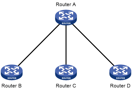
As shown in Figure 5, Router A sends RR messages to the downstream devices (Router B, Router C, and Router D) to change their prefix to be advertised in RAs.
Restrictions and guidelines
You must enable router renumbering on the downstream router interfaces before they receive and process RR packets.
Procedure
1. Enter system view.
system-view
2. Enter interface view.
interface interface-type interface-number
3. Enable router renumbering.
ipv6 router-renumber enable
By default, router renumbering is disabled.
Enabling IPv6 local fragment reassembly
About this task
Use this feature on a device to improve fragment reassembly efficiency. An LPU performs fragment reassembly for an IPv6 packet destined for the device if it receives fragments of that packet. If this feature is disabled, all IPv6 fragments are delivered to the active MPU for reassembly.
Restrictions and guidelines
This feature fails to reassemble an IPv6 packet if fragments of the packet are received by different LPUs.
Procedure
1. Enter system view.
system-view
2. Enable IPv6 local fragment reassembly.
ipv6 reassemble local enable
By default, IPv6 local fragment reassembly is disabled.
Configuring IPv6 bandwidth-based load sharing
About this task
This feature shares IPv6 traffic among multiple output interfaces based on their expected load percentages. The device calculates the load percentage for each output interface in terms of the interface expected bandwidth.
For devices that run load sharing protocols such as Locator/ID Separation Protocol (LISP), they implement load sharing based on the ratios defined by these protocols.
Procedure
1. Enter system view.
system-view
2. Enable IPv6 bandwidth-based load sharing.
ipv6 bandwidth-based-sharing
By default, IPv6 bandwidth-based load sharing is disabled.
3. Enter interface view.
interface interface-type interface-number
4. Set the expected bandwidth of an interface.
bandwidth bandwidth
By default, the expected bandwidth of an interface equals the absolute bandwidth of the link.
Disabling processing the source route option
About this task
The source route option in the IPv6 routing header (a type of IPv6 extension header) is used for network diagnosis and specific service transmission. By default, the device supports processing the source route option. If the option is forged by an attacker, the device will obtain incorrect source route information, affecting network diagnosis and service transmission. To avoid the situation, you can execute the undo ipv6 option source-route enable command to drop IPv6 packets that contain the source route option.
Restrictions and guidelines
Before you enable or disable this feature, make sure you have fully evaluated the probability of the source route option attack in the network.
Procedure
1. Enter system view.
system-view
2. Disable processing IPv6 packets that contain the source route option.
undo ipv6 option source-route enable
By default, the device processes IPv6 packets that contain the source route option.
Enabling Layer 3 packet statistics collection
About this task
With this feature enabled on an interface, the device counts incoming and outgoing IPv4 and IPv6 packets on the interface. To display the collected statistics, execute the display ip interface, display ip statistics, display ipv6 interface, and display ipv6 statistics commands.
For more information about the related display commands, see Layer 3—IP Services Command Reference.
Restrictions and guidelines
When the interface is processing a large number of packets, Layer 3 packet statistics collection will cause high CPU usage and degrade the forwarding performance. If the statistics are not necessary, to ensure the device performance, disable this feature.
Procedure
1. Enter system view.
system-view
2. Enter interface view.
interface interface-type interface-number
3. Enable Layer 3 packet statistics collection.
statistics l3-packet enable
By default, Layer 3 packet statistics collection is disabled.
Specifying the maximum number of IPv6 FIB entries on an interface module
About this task
By default, the maximum number of IPv6 FIB entries on an interface module is the maximum number of IPv6 FIB entries supported by the device. To save memory resources, you can perform this task to decrease the maximum number of IPv6 FIB entries on an interface module.
Restrictions and guidelines
If the value for the max-number argument exceeds the maximum number supported by the device, the configuration does not take effect on interface modules. The maximum number supported by the device is then applied to the interface modules.
If the number of IPv6 FIB entries has reached max-number on an interface module, the module stops accepting new IPv6 FIB entries issued by the MPU. The existing services on the module are not affected. If the MPU deletes some old IPv6 FIB entries and notifies the interface module to delete the entries, the interface module can accept new IPv6 FIB entries until the upper limit is reached again.
Procedure
1. Enter system view.
system-view
2. Specify the maximum number of IPv6 FIB entries on an interface module.
ipv6 fib max-number max-number slot slot-number
By default, the maximum number of IPv6 FIB entries on an interface module is the maximum number of IPv6 FIB entries supported by the device.
Display and maintenance commands for IPv6 basics
Execute display commands in any view and reset commands in user view.
For information about the display tcp statistics, display udp statistics, reset tcp statistics, and reset udp statistics command, see the IP performance commands in Layer 3—IP Services Command Reference.
|
Task |
Command |
|
Display IPv6 FIB entries. |
display ipv6 fib [ srv6 [ end | end-dt2m | end-dt2u | end-dt2ul | end-dt4 | end-dt46 | end-dt6 | end-dx2 | end-dx2l | end-dx4 | end-dx6 | end-op | end-otp | end-t | end-x ] | [ vpn-instance vpn-instance-name ] [ ipv6-address [ prefix-length ] ] [ slot slot-number ] |
|
Display IPv6 FIB entry statistics. |
display ipv6 fib count [ all | vpn-instance vpn-instance-name ] slot slot-number |
|
Display ICMPv6 traffic statistics. |
display ipv6 icmp statistics [ slot slot-number ] |
|
Display IPv6 information about the interface. |
display ipv6 interface [ interface-type [ interface-number ] ] [ brief ] |
|
Display IPv6 prefix information about the interface. |
display ipv6 interface interface-type interface-number prefix |
|
Display statistics about dropped IPv6 packets that contain the source route option. |
display ipv6 option source-route statistics [ slot slot-number ] |
|
Display the IPv6 path MTU information. |
display ipv6 pathmtu [ vpn-instance vpn-instance-name ] { ipv6-address | { all | dynamic | static } [ count ] } |
|
Display the IPv6 prefix information. |
display ipv6 prefix [ prefix-number ] |
|
Display brief information about IPv6 RawIP connections. |
display ipv6 rawip [ slot slot-number ] |
|
Display detailed information about IPv6 RawIP connections. |
display ipv6 rawip verbose [ slot slot-number [ pcb pcb-index ] ] |
|
Display router renumbering statistics. |
display ipv6 router-renumber statistics |
|
Display IPv6 and ICMPv6 packet statistics. |
display ipv6 statistics [ slot slot-number ] |
|
Display brief information about IPv6 TCP connections. |
display ipv6 tcp [ slot slot-number ] |
|
Display detailed information about IPv6 TCP connections. |
display ipv6 tcp verbose [ slot slot-number [ pcb pcb-index ] ] |
|
Display brief information about IPv6 TCP proxy. |
display ipv6 tcp-proxy slot slot-number |
|
Display the usage of non-well-known ports for IPv6 TCP proxy. |
display ipv6 tcp-proxy port-info slot slot-number |
|
Display brief information about IPv6 UDP connections. |
display ipv6 udp [ slot slot-number ] |
|
Display detailed information about IPv6 UDP connections. |
display ipv6 udp verbose [ slot slot-number [ pcb pcb-index ] ] |
|
Display IPv6 TCP traffic statistics. |
display tcp statistics [ slot slot-number ] |
|
Display IPv6 UDP traffic statistics. |
display udp statistics [ slot slot-number ] |
|
Clear statistics about dropped IPv6 packets that contain the source route option. |
reset ipv6 option source-route statistics |
|
Clear path MTUs. |
reset ipv6 pathmtu { all | dynamic | static } |
|
Clear router renumbering statistics. |
reset ipv6 router-renumber statistics |
|
Clear IPv6 and ICMPv6 packet statistics. |
reset ipv6 statistics [ slot slot-number ] |
|
Clear IPv6 TCP traffic statistics. |
reset tcp statistics |
|
Clear IPv6 UDP traffic statistics. |
reset udp statistics |
|
|
NOTE: Configure the statistics l3-packet enable command if you want the following fields to reflect the accurate statistics: · The IPv6 Packet statistics field in the display ipv6 interface command output. · All fields in the display ipv6 statistics command output. The Layer 3 statistics counting allows the device to collect incoming and outgoing IP packets for the interface. Such statistics counting might cause high CPU usage and degrade the device performance. If the statistics are not necessary, to ensure the device performance, do not configure the statistics l3-packet enable command. |
Basic IPv6 settings configuration examples
Example: Configuring basic IPv6 settings
Network configuration
As shown in Figure 6, configure IPv6 addresses for the routers and verify that they can reach each other. Configure a route to the host on Router B. Enable IPv6 for the host to automatically obtain an IPv6 address through IPv6 ND. The host has a route to Router B.

Procedure
1. Configure Router A:
# Configure a global unicast address for interface Ten-GigabitEthernet 3/0/1.
<RouterA> system-view
[RouterA] interface ten-gigabitethernet 3/0/1
[RouterA-Ten-GigabitEthernet3/0/1] ipv6 address 3001::1/64
[RouterA-Ten-GigabitEthernet3/0/1] quit
# Configure a global unicast address for interface Ten-GigabitEthernet 3/0/2 and enable it to advertise RA messages (an interface does not advertises RA messages by default).
[RouterA] interface ten-gigabitethernet 3/0/2
[RouterA-Ten-GigabitEthernet3/0/2] ipv6 address 2001::1/64
[RouterA-Ten-GigabitEthernet3/0/2] undo ipv6 nd ra halt
[RouterA-Ten-GigabitEthernet3/0/2] quit
2. Configure Router B:
# Configure a global unicast address for interface Ten-GigabitEthernet 3/0/1.
<RouterB> system-view
[RouterB] interface ten-gigabitethernet 3/0/1
[RouterB-Ten-GigabitEthernet3/0/1] ipv6 address 3001::2/64
[RouterB-Ten-GigabitEthernet3/0/1] quit
# Configure an IPv6 static route to the host.
[RouterB] ipv6 route-static 2001:: 64 3001::1
3. Configure the host:
Enable IPv6 on the host to automatically obtain an IPv6 address through IPv6 ND.
# Display neighbor information for Ten-GigabitEthernet 3/0/2 on Router A.
[RouterA] display ipv6 neighbors interface ten-gigabitethernet 3/0/2
Type: S-Static D-Dynamic O-Openflow R-Rule IS-Invalid static
IPv6 address MAC address VLAN/VSI Interface State T Aging
FE80::215:E9FF:FEA6:7D14 0015-e9a6-7d14 -- XGE3/0/2 STALE D 1238
2001::15B:E0EA:3524:E791 0015-e9a6-7d14 -- XGE3/0/2 STALE D 1248
The output shows that the IPv6 global unicast address that the host obtained is 2001::15B:E0EA:3524:E791.
Verifying the configuration
# Display IPv6 interface information on Router A.
[RouterA] display ipv6 interface ten-gigabitethernet 3/0/1
Ten-GigabitEthernet3/0/1 current state: UP
Line protocol current state: UP
IPv6 is enabled, link-local address is FE80::20F:E2FF:FE00:2
Global unicast address(es):
3001::1, subnet is 3001::/64
Joined group address(es):
FF02::1
FF02::2
FF02::1:FF00:1
FF02::1:FF00:2
MTU is 1500 bytes
ND DAD is enabled, number of DAD attempts: 1
ND reachable time is 1200000 milliseconds
ND retransmit interval is 1000 milliseconds
Hosts use stateless autoconfig for addresses
IPv6 Packet statistics:
InReceives: 25829
InTooShorts: 0
InTruncatedPkts: 0
InHopLimitExceeds: 0
InBadHeaders: 0
InBadOptions: 0
ReasmReqds: 0
ReasmOKs: 0
InFragDrops: 0
InFragTimeouts: 0
OutFragFails: 0
InUnknownProtos: 0
InDelivers: 47
OutRequests: 89
OutForwDatagrams: 48
InNoRoutes: 0
InTooBigErrors: 0
OutFragOKs: 0
OutFragCreates: 0
InMcastPkts: 6
InMcastNotMembers: 25747
OutMcastPkts: 48
InAddrErrors: 0
InDiscards: 0
OutDiscards: 0
[RouterA] display ipv6 interface ten-gigabitethernet 3/0/2
Ten-GigabitEthernet3/0/2 current state: UP
Line protocol current state: UP
IPv6 is enabled, link-local address is FE80::20F:E2FF:FE00:1C0
Global unicast address(es):
2001::1, subnet is 2001::/64
Joined group address(es):
FF02::1
FF02::2
FF02::1:FF00:1
FF02::1:FF00:1C0
MTU is 1500 bytes
ND DAD is enabled, number of DAD attempts: 1
ND reachable time is 1200000 milliseconds
ND retransmit interval is 1000 milliseconds
ND advertised reachable time is 0 milliseconds
ND advertised retransmit interval is 0 milliseconds
ND router advertisements are sent every 600 seconds
ND router advertisements live for 1800 seconds
Hosts use stateless autoconfig for addresses
IPv6 Packet statistics:
InReceives: 272
InTooShorts: 0
InTruncatedPkts: 0
InHopLimitExceeds: 0
InBadHeaders: 0
InBadOptions: 0
ReasmReqds: 0
ReasmOKs: 0
InFragDrops: 0
InFragTimeouts: 0
OutFragFails: 0
InUnknownProtos: 0
InDelivers: 159
OutRequests: 1012
OutForwDatagrams: 35
InNoRoutes: 0
InTooBigErrors: 0
OutFragOKs: 0
OutFragCreates: 0
InMcastPkts: 79
InMcastNotMembers: 65
OutMcastPkts: 938
InAddrErrors: 0
InDiscards: 0
OutDiscards: 0
# Display IPv6 interface information on Router B.
[RouterB] display ipv6 interface ten-gigabitethernet 3/0/1
Ten-GigabitEthernet3/0/1 current state: UP
Line protocol current state: UP
IPv6 is enabled, link-local address is FE80::20F:E2FF:FE00:1234
Global unicast address(es):
3001::2, subnet is 3001::/64
Joined group address(es):
FF02::1
FF02::2
FF02::1:FF00:2
FF02::1:FF00:1234
MTU is 1500 bytes
ND DAD is enabled, number of DAD attempts: 1
ND reachable time is 1200000 milliseconds
ND retransmit interval is 1000 milliseconds
Hosts use stateless autoconfig for addresses
IPv6 Packet statistics:
InReceives: 117
InTooShorts: 0
InTruncatedPkts: 0
InHopLimitExceeds: 0
InBadHeaders: 0
InBadOptions: 0
ReasmReqds: 0
ReasmOKs: 0
InFragDrops: 0
InFragTimeouts: 0
OutFragFails: 0
InUnknownProtos: 0
InDelivers: 117
OutRequests: 83
OutForwDatagrams: 0
InNoRoutes: 0
InTooBigErrors: 0
OutFragOKs: 0
OutFragCreates: 0
InMcastPkts: 28
InMcastNotMembers: 0
OutMcastPkts: 7
InAddrErrors: 0
InDiscards: 0
OutDiscards: 0
# Ping Router A and Router B from the host, and ping Router A and the host from Router B to verify that they can reach each other.
|
|
NOTE: To ping a link-local address, use the –i parameter to specify an interface for the link-local address. |
[RouterB] ping ipv6 -c 1 3001::1
Ping6(56 data bytes) 3001::2 --> 3001::1, press CTRL+C to break
56 bytes from 3001::1, icmp_seq=0 hlim=64 time=4.404 ms
--- Ping6 statistics for 3001::1 ---
1 packet(s) transmitted, 1 packet(s) received, 0.0% packet loss
round-trip min/avg/max/std-dev = 4.404/4.404/4.404/0.000 ms
[RouterB] ping ipv6 -c 1 2001::15B:E0EA:3524:E791
Ping6(56 data bytes) 3001::2 --> 2001::15B:E0EA:3524:E791, press CTRL+C to break
56 bytes from 2001::15B:E0EA:3524:E791, icmp_seq=0 hlim=64 time=5.404 ms
--- Ping6 statistics for 2001::15B:E0EA:3524:E791 ---
1 packet(s) transmitted, 1 packet(s) received, 0.0% packet loss
round-trip min/avg/max/std-dev = 5.404/5.404/5.404/0.000 ms
The output shows that Router B can ping Router A and the host. The host can also ping Router B and Router A (output not shown).
Configuring IPv6 neighbor discovery
About IPv6 neighbor discovery
ICMPv6 messages used by IPv6 neighbor discovery
The IPv6 neighbor discovery (ND) process uses ICMP messages for address resolution, neighbor reachability verification, and neighboring device tracking.
Table 3 describes the ICMPv6 messages used by the IPv6 ND protocol.
Table 3 ICMPv6 messages used by ND
|
ICMPv6 message |
Type |
Function |
|
Neighbor Solicitation (NS) |
135 |
Acquires the link-layer address of a neighbor on the local link. |
|
Verifies the reachability of a neighbor. |
||
|
Detects duplicate addresses. |
||
|
Neighbor Advertisement (NA) |
136 |
Responds to an NS message. |
|
Notifies the neighboring nodes of link layer changes. |
||
|
Router Solicitation (RS) |
133 |
Requests an address prefix and other configuration information for autoconfiguration after startup. |
|
Router Advertisement (RA) |
134 |
Responds to an RS message. |
|
Advertises information, such as the Prefix Information options and flag bits. |
||
|
Redirect |
137 |
Informs the source host of a better next hop on the path to a particular destination when certain conditions are met. |
Restrictions and guidelines
The device discards received NS, NA, RS, and RA packets if the packet TTL is not 255.
Address resolution
This function is similar to ARP in IPv4. An IPv6 node acquires the link-layer addresses of neighboring nodes on the same link through NS and NA messages.
Figure 7 shows how Host A acquires the link-layer address of Host B on the same link. The address resolution procedure is as follows:
1. Host A multicasts an NS message. The source address of the NS message is the IPv6 address of the sending interface of Host A. The destination address is the solicited-node multicast address of Host B. The NS message body contains the link-layer address of Host A and the target IPv6 address.
2. After receiving the NS message, Host B determines whether the target address of the packet is its IPv6 address. If it is, Host B learns the link-layer address of Host A, and then unicasts an NA message containing its link-layer address.
3. Host A acquires the link-layer address of Host B from the NA message.

Neighbor reachability detection
After Host A acquires the link-layer address of its neighbor Host B, Host A can use NS and NA messages to test the reachability of Host B as follows:
1. Host A sends an NS message whose destination address is the IPv6 address of Host B.
2. If Host A receives an NA message from Host B, Host A decides that Host B is reachable. Otherwise, Host B is unreachable.
Duplicate address detection
After Host A acquires an IPv6 address, it performs Duplicate Address Detection (DAD) to check whether the address is being used by any other node. This is similar to gratuitous ARP in IPv4. DAD is accomplished through NS and NA messages.
The DAD procedure is as follows:
1. Host A sends an NS message. The source address is the unspecified address and the destination address is the corresponding solicited-node multicast address of the IPv6 address to be detected. The NS message body contains the detected IPv6 address.
2. If Host B uses this IPv6 address, Host B returns an NA message that contains its IPv6 address.
3. Host A knows that the IPv6 address is being used by Host B after receiving the NA message from Host B. If receiving no NA message, Host A decides that the IPv6 address is not in use and uses this address.
Figure 8 Duplicate address detection

Router/prefix discovery and stateless address autoconfiguration
Router/prefix discovery allows an IPv6 node to find the neighboring routers and learn the prefix and network configuration parameters of the network from receiving RA messages.
Stateless address autoconfiguration allows an IPv6 node to automatically generate an IPv6 address based on the information learned through router/prefix discovery.
A node performs router/prefix discovery and stateless address autoconfiguration as follows:
1. At startup, a node sends an RS message to request configuration information from a router.
2. The router returns an RA message containing the Prefix Information option and other configuration information. (The router also periodically sends an RA message.)
3. The node automatically generates an IPv6 address and other configuration parameters according to the configuration information in the RA message.
The Prefix Information option contains an address prefix and the preferred lifetime and valid lifetime of the address prefix. A node updates the preferred lifetime and valid lifetime upon receiving a periodic RA message.
The generated IPv6 address is valid within the valid lifetime and becomes invalid when the valid lifetime expires.
After the preferred lifetime expires, the node cannot use the generated IPv6 address to establish new connections, but can receive packets destined for the IPv6 address. The preferred lifetime cannot be greater than the valid lifetime.
Redirection
Upon receiving a packet from a host, the gateway sends an ICMPv6 redirect message to inform the host of a better next hop when the following conditions are met:
· The interface receiving the packet is the same as the interface forwarding the packet.
· The selected route is not created or modified by an ICMPv6 redirect message.
· The selected route is not a default route on the device.
· The forwarded IPv6 packet does not contain the routing extension header.
Protocols and standards
· RFC 4861, Neighbor Discovery for IP Version 6 (IPv6)
· RFC 8106, IPv6 Router Advertisement Options for DNS Configuration
IPv6 neighbor discovery tasks at a glance
All IPv6 neighbor discovery tasks are optional.
· Configuring a static neighbor entry
· Setting the dynamic neighbor learning limit
· Enabling unsolicited NA learning
· Enabling learning ND information from a different subnet
· Setting the aging timer for ND entries in stale state
· Minimizing link-local ND entries
· Configuring RA message sending and parameters
· Setting the maximum number of attempts to send an NS message for DAD
· Enabling duplicate detection for duplicate addresses
¡ Enabling inter-VLAN ND proxy
· Configuring IPv6 ND direct route advertisement
· Enabling recording user IPv6 address conflicts
· Enabling recording ND entry learning events
Configuring a static neighbor entry
About this task
A neighbor entry stores information about a link-local node. The entry can be created dynamically through NS and NA messages, or configured statically.
The device uniquely identifies a static neighbor entry by using the neighbor's IPv6 address and the number of the Layer 3 interface that connects to the neighbor. You can configure a static neighbor entry by using one of the following methods:
· Method 1—Associate a neighbor's IPv6 address and link-layer address with the local Layer 3 interface.
· Method 2—Associate a neighbor's IPv6 address and link-layer address with a Layer 2 port in a VLAN.
· Method 3—Specify a neighbor IPv6 address, MAC address, input interface (VSI interface), output interface (tunnel interface), and VSI name.
· Method 4—Specify a neighbor IPv6 address, MAC address, input interface (VSI interface), output interface (determined by a Layer 2 interface and Ethernet service instance), and VSI name.
Restrictions and guidelines
To configure a static neighbor entry for a VLAN interface, use Method 1 or Method 2.
· If you use Method 1, the device is required to resolve the Layer 2 port in the related VLAN.
· If you use Method 2, make sure the Layer 2 port belongs to the specified VLAN and the corresponding VLAN interface already exists. After the configuration, the device associates the VLAN interface with the neighbor IPv6 address to identify the static neighbor entry.
If the device and its neighbor are connected through a VSI interface, use Method 3 or Method 4 to configure the neighbor entry.
· If Method 3 is used, the neighbor entry is in REACH state. This method is applicable to the network where VXLAN gateways are connected through tunnel interfaces. In the network, a VXLAN gateway is identified by both the VSI and VSI interface. A VSI interface is associated with multiple tunnel interfaces. To create a neighbor entry, you must specify the VSI interface, VSI, and tunnel interface.
· If Method 4 is used, the neighbor entry is in REACH state. This method is applicable to the network where VXLAN gateways are associated with local sites. A VXLAN gateway is identified by both the VSI and VSI interface. One VXLAN gateway might have multiple local sites. Local sites access the VXLAN network through Layer 2 interfaces where Ethernet service instance and VSI mappings are configured. To create a neighbor entry, you must specify the VSI interface, Layer 2 interface connected to the local site, Ethernet service instance, and VSI.
For more information about VSI, VSI interfaces, and Ethernet service instances, see VXLAN overview in VXLAN Configuration Guide.
For more information about tunnel interfaces, see tunneling configuration in Layer 3—IP Services Configuration Guide.
To delete a static neighbor entry for a VSI interface, specify only the VSI interface.
To delete a static neighbor entry for a VLAN interface, specify only the VLAN interface.
You can use the undo ipv6 neighbor command to delete both static and dynamic neighbor entries.
Procedure
1. Enter system view.
system-view
2. Configure a static neighbor entry.
ipv6 neighbor ipv6-address mac-address { vlan-id port-type port-number | interface interface-type interface-number | vsi-interface vsi-interface-id tunnel number vsi vsi-name | vsi-interface vsi-interface-id interface-type interface-number service-instance instance-id vsi vsi-name } [ vpn-instance vpn-instance-name ]
By default, no static neighbor entries exist.
Setting the dynamic neighbor learning limit
About this task
The device can dynamically acquire the link-layer address of a neighboring node through NS and NA messages and add it into the neighbor table. A large neighbor table degrades the forwarding performance. To avoid excessive resource consumption by neighbor entries, use one of the following methods:
· Set the maximum number of dynamic neighbor entries that an interface can learn. When the number of dynamic neighbor entries reaches the limit, the interface stops learning neighbor information.
· Set the maximum number of dynamic neighbor entries that the device can learn. When the number of dynamic neighbor entries reaches the limit, the device stops learning neighbor information.
The number of dynamic neighbor entries learnt by the interfaces on a device cannot exceed the maximum number of dynamic neighbor entries that the device can learn.
Setting the maximum number of dynamic neighbor entries on an interface
system-view
2. Enter interface view.
interface interface-type interface-number
3. Set the dynamic neighbor learning limit on the interface.
ipv6 neighbors max-learning-num max-number
By default, the dynamic neighbor learning limit on the interface is 524288.
Setting the maximum number of dynamic neighbor entries on the device.
1. Enter system view.
system-view
2. Set the dynamic neighbor learning limit on the device.
ipv6 neighbors max-learning-number max-number slot slot-number
By default, the dynamic neighbor learning limit on the device is 524288.
To disable the device from learning dynamic neighbor entries, set the value for the max-number argument to 0.
Enabling unsolicited NA learning
About this task
On some networks, a server multicasts NA messages to two peer devices for link backup. The peer devices cannot learn ND entry for the server from these NA messages by default. If no ND learning is triggered by data exchange between the server and peer devices, the peer devices learn the entry for the server only when the server unicasts messages to them.
This feature enables an interface to learn ND entries from unsolicited NA messages. The ND entries generated by using this method are in stale state.
Restrictions and guidelines
To ensure that the device learns ND entries from trusted NA messages, enable this feature only on a secure network.
This feature might cause the device to learn excessive ND entries that consume too many system resources. As a best practice, execute the ipv6 neighbor stale-aging command to set a smaller aging timer before you enable this feature. The smaller aging timer accelerates the aging of ND entries in stale state.
This feature is available only on Layer 3 interfaces.
Procedure
1. Enter system view.
system-view
2. Enter Layer 3 interface view.
interface interface-type interface-number
3. Enable unsolicited NA learning.
ipv6 nd unsolicited-na-learning enable
By default, unsolicited NA learning is disabled.
Enabling learning ND information from a different subnet
About this task
With this feature enabled, when an interface receives an NS packet from a node in a different subnet, it returns an NA packet and generates a host route with a 128-bit prefix in the FIB table. If uRPF is enabled on the interface, packets from the node to the interface will be discarded because the source IP address cannot match any unicast route in the FIB table and loss uRPF check fails. To avoid such packets from being discarded by uRPF, disable learning ND information from a different subnet as a best practice. For more information about uRPF, see Security Configuration Guide.
Restrictions and guidelines
You can configure this feature globally or for specific interfaces. When this feature is disabled globally, you cannot enable it for any interfaces.
With this feature disabled, an interface can learn only ND information from the subnet in which the interface is in.
Enabling learning ND information from a different subnet globally
1. Enter system view.
system-view
2. Enable learning ND information from a different subnet.
|
|
CAUTION: Disabling this feature deletes existing ND entries learned from different subnets, and might disconnect sessions to the subnets. |
ipv6 nd span-segment-learning enable
By default, learning ND information from a different subnet is disabled.
Enabling learning ND information from a different subnet on an interface
1. Enter system view.
system-view
2. Enter interface view.
interface interface-type interface-number
3. Enable learning ND information from a different subnet.
|
|
CAUTION: Disabling this feature deletes existing ND entries learned from different subnets, and might disconnect sessions to the subnets. |
ipv6 nd span-segment-learning enable
By default, learning ND information from a different subnet is disabled.
Setting the aging timer for ND entries in stale state
About this task
ND entries in stale state have an aging timer. If an ND entry in stale state is not refreshed before the timer expires, the ND entry changes to the delay state. If it is still not refreshed in 5 seconds, the ND entry changes to the probe state, and the device sends an NS message three times. If no response is received, the device deletes the ND entry.
Procedure
1. Enter system view.
system-view
2. Set the aging timer for ND entries in stale state.
ipv6 neighbor stale-aging aging-time
The default setting is 240 minutes.
Minimizing link-local ND entries
About this task
Perform this task to minimize link-local ND entries assigned to the hardware. Link-local ND entries refer to ND entries that contain link-local addresses.
By default, the device assigns all ND entries to the hardware. With this feature enabled, the newly learned link-local ND entries are not assigned to the hardware if the link-local addresses of the entries are not the next hops of any routes. This feature saves hardware resources.
This feature takes effect only on newly learned link-local ND entries.
Procedure
1. Enter system view.
system-view
2. Minimize link-local ND entries.
ipv6 neighbor link-local minimize
By default, the device assigns all ND entries to the hardware.
Setting the hop limit
About this task
You can set the hop limit value to fill in the Hop Limit field for IPv6 packets to be sent.
Procedure
1. Enter system view.
system-view
2. Set the value for the Hop Limit field in the IP header.
ipv6 hop-limit value
The default setting is 64.
Configuring RA message sending and parameters
About RA message parameters
You can enable an interface to send RA messages, and configure the interval for sending RA messages and parameters in RA messages. After receiving an RA message, a host can use these parameters to perform corresponding operations. Table 4 describes the configurable parameters in an RA message.
Table 4 Parameters in an RA message and their descriptions
|
Parameter |
Description |
|
Hop Limit |
Maximum number of hops in RA messages. A host receiving the RA message fills the value in the Hop Limit field of sent IPv6 packets. |
|
Prefix information |
After receiving the prefix information, the hosts on the same link can perform stateless autoconfiguration. |
|
MTU |
Guarantees that all nodes on the link use the same MTU. |
|
M flag |
Determines whether a host uses stateful autoconfiguration to obtain an IPv6 address. If the M flag is set to 1, the host uses stateful autoconfiguration (for example, from a DHCPv6 server) to obtain an IPv6 address. Otherwise, the host uses stateless autoconfiguration to generate an IPv6 address. |
|
O flag |
Determines whether a host uses stateful autoconfiguration to obtain configuration information other than the IPv6 address. If the O flag is set to 1, the host uses stateful autoconfiguration (for example, from a DHCPv6 server) to obtain configuration information other than the IPv6 address. Otherwise, the host uses stateless autoconfiguration. |
|
Router Lifetime |
Tells the receiving hosts how long the advertising router can live. If the lifetime of a router is 0, the router cannot be used as the default gateway. |
|
Retrans Timer |
If the device does not receive a response message within the specified time after sending an NS message, it retransmits the NS message. |
|
Reachable Time |
If the neighbor reachability detection shows that a neighbor is reachable, the device considers the neighbor reachable within the specified reachable time. If the device needs to send a packet to the neighbor after the specified reachable time expires, the device reconfirms whether the neighbor is reachable. |
|
Router Preference |
Specifies the router preference in an RA message. A host selects a router as the default gateway according to the router preference. If router preferences are the same, the host selects the router from which the first RA message is received. |
|
DNS server option |
DNS server information for IPv6 hosts. Hosts can obtain DNS server information from received RA messages instead of using DHCPv6. |
|
DNS suffix information in DNS Search List (DNSSL) option |
DNS suffix information for IPv6 hosts. Hosts can obtain DNS suffix information from received RA messages instead of using DHCPv6. |
Restrictions and guidelines
The maximum interval for sending RA messages should be less than (or equal to) the router lifetime in RA messages. In this way, the router can be updated by an RA message before expiration.
The values of the NS retransmission timer and the reachable time configured for an interface are sent in RA messages to hosts. This interface sends NS messages at the interval of the NS retransmission timer and considers a neighbor reachable within the reachable time.
Enabling the sending of RA messages
1. Enter system view.
system-view
2. Enter interface view.
interface interface-type interface-number
3. Enable the sending of RA messages.
undo ipv6 nd ra halt
The default setting is disabled.
4. Set the maximum and minimum intervals for sending RA messages.
ipv6 nd ra interval max-interval min-interval
By default, the maximum interval for sending RA messages is 600 seconds, and the minimum interval is 200 seconds.
The device sends RA messages at random intervals between the maximum interval and the minimum interval.
The minimum interval should be less than or equal to 0.75 times the maximum interval.
Configuring parameters for RA messages
1. Enter system view.
system-view
2. Enter interface view.
interface interface-type interface-number
3. Configure the prefix information in RA messages.
ipv6 nd ra prefix { ipv6-prefix prefix-length | ipv6-prefix/prefix-length } [ valid-lifetime preferred-lifetime [ no-autoconfig | off-link ] * | no-advertise ]
By default, no prefix information is configured for RA messages, and the IPv6 address of the interface sending RA messages is used as the prefix information. If the IPv6 address is manually configured, the prefix uses a fixed valid lifetime of 2592000 seconds (30 days) and a preferred lifetime of 604800 seconds (7 days). If the IPv6 address is automatically obtained, the prefix uses the valid lifetime and preferred lifetime configured for the IPv6 address.
4. Configure the default settings for prefixes advertised in RA messages.
ipv6 nd ra prefix default [ valid-lifetime preferred-lifetime [ no-autoconfig | off-link ] * | no-advertise ]
By default, no default settings are configured for prefixes advertised in RA messages.
5. Turn off the MTU option in RA messages.
ipv6 nd ra no-advlinkmtu
By default, RA messages contain the MTU option.
6. Specify unlimited hops in RA messages.
ipv6 nd ra hop-limit unspecified
By default, the maximum number of hops in RA messages is 64.
7. Set the M flag bit to 1.
ipv6 nd autoconfig managed-address-flag
By default, the M flag bit is set to 0 in RA advertisements. Hosts receiving the advertisements will obtain IPv6 addresses through stateless autoconfiguration.
8. Set the O flag bit to 1.
ipv6 nd autoconfig other-flag
By default, the O flag bit is set to 0 in RA advertisements. Hosts receiving the advertisements will acquire other configuration information through stateless autoconfiguration.
9. Set the router lifetime in RA messages.
ipv6 nd ra router-lifetime time
By default, the router lifetime is three times the maximum interval for advertising RA messages.
10. Set the NS retransmission timer.
ipv6 nd ns retrans-timer value
By default, an interface sends NS messages every 1000 milliseconds, and the value of the Retrans Timer field in RA messages is 0.
11. Set the router preference in RA messages.
ipv6 nd router-preference { high | low | medium }
By default, the router preference is medium.
12. Set the reachable time.
ipv6 nd nud reachable-time time
By default, the neighbor reachable time is 1200000 milliseconds, and the value of the Reachable Time field in sent RA messages is 0.
Specifying DNS server information in RA messages
About this task
The DNS server options in RA messages provide DNS server information for IPv6 hosts. The RA messages allow hosts to obtain their IPv6 addresses and the DNS server through stateless autoconfiguration. This method is useful in a network where DHCPv6 infrastructure is not provided.
One DNS server option contains one DNS server. All DNS server options are sorted in ascending order of the DNS server sequence number.
After you execute the ipv6 nd ra dns server command, the device immediately sends an RA message with the existing and newly specified DNS server information.
After you execute the undo ipv6 nd ra dns server command, the device immediately sends two RA messages.
· The first RA message contains information about all DNS servers, including the DNS servers specified in the undo command with their lifetime set to 0 seconds.
· The second RA message contains information about remaining DNS servers.
Each time the device sends an RA message from an interface, it immediately refreshes the RA message advertisement interval for that interface.
Restrictions and guidelines
You can configure a maximum of eight DNS servers on an interface.
The default lifetime of a DNS server is three times the maximum interval for advertising RA messages. To set the maximum interval, use the ipv6 nd ra interval command.
In an IPv6 environment, PPP users and IPoE IPv6-ND-RS users can obtain the IPv6 DNS server address through AAA authorization. This AAA-authorized IPv6 DNS server address is also carried in RA messages. If an interface obtains the AAA-authorized and manually specified IPv6 DNS server addresses, the RA messages contain both, with the AAA-authorized address in the front. When the two addresses conflict, the AAA-authorized DNS-related attributes are used.
For more information about the PPP support for IPv6, see PPP configuration in Layer 2—WAN Access Configuration Guide.
For more information about IPoE IPv6-ND-RS users, see IPoE configuration in BRAS Services Configuration Guide.
Procedure
1. Enter system view.
system-view
2. Enter interface view.
interface interface-type interface-number
3. Specify DNS server information to be advertised in RA messages.
ipv6 nd ra dns server ipv6-address [ seconds | infinite ] sequence seqno
By default, no DNS server information is specified and RA messages do not contain DNS server options.
Specifying DNS suffix information in RA messages
About this task
The DNSSL option in RA messages provides suffix information for IPv6 hosts. The RA messages allow hosts to obtain their IPv6 addresses and the DNS suffix through stateless autoconfiguration. This method is useful in a network where DHCPv6 infrastructure is not provided.
One DNSSL option contains one DNS suffix. All DNSSL options are sorted in ascending order of the sequence number of the DNS suffix.
After you execute the ipv6 nd ra dns search-list command, the device immediately sends an RA message with the existing and newly specified DNS suffix information.
After you execute the undo ipv6 nd ra dns search-list command, the device immediately sends two RA messages.
· The first RA message contains information about all DNS suffixes, including DNS suffixes specified in the undo command with their lifetime set to 0 seconds.
· The second RA message contains information about remaining DNS suffixes.
Each time the device sends an RA message from an interface, it immediately refreshes the RA message advertisement interval for that interface.
Restrictions and guidelines
You can configure a maximum of eight DNS suffixes on an interface.
The default lifetime of a DNS suffix is three times the maximum interval for advertising RA messages. To set the maximum interval, use the ipv6 nd ra interval command.
Procedure
1. Enter system view.
system-view
2. Enter interface view.
interface interface-type interface-number
3. Specify DNS suffix information to be advertised in RA messages.
ipv6 nd ra dns search-list domain-name [ seconds | infinite ] sequence seqno
By default, no DNS suffix information is specified and RA messages do not contain DNS suffix options.
Suppressing advertising DNS information in RA messages
About this task
Perform this task to suppress the device from advertising information about DNS server addresses and DNS suffixes in RA messages.
Whether enabling this feature on an interface will trigger sending RA message immediately depends on the interface configuration:
· If the interface has DNS server information configured or has obtained an AAA-authorized DNS server address, the device immediately sends two RA messages. In the first message, the lifetime for DNS server addresses is 0 seconds. The second RA message does not contain any DNS server options.
· If the interface has no DNS server information specified and no AAA-authorized DNS server address assigned, no RA messages are triggered.
If you specify a new DNS server or remove a DNS server on the interface after enabling DNS server suppression, the device immediately sends an RA message without any DNS server options.
Whether disabling this feature on an interface will trigger sending RA message immediately depends on the interface configuration:
· If the interface has DNS server information configured or has obtained an AAA-authorized DNS server address, the device immediately sends an RA message containing the DNS server information.
· If the interface has no DNS server information specified and no AAA-authorized DNS server address assigned, no RA messages are triggered.
Each time the device sends an RA message from an interface, it immediately refreshes the RA message advertisement interval for that interface.
The same suppression mechanism applies when you enable or disable DNS suffix suppression in RA messages.
Procedure
1. Enter system view.
system-view
2. Enter interface view.
interface interface-type interface-number
3. Enable DNS server suppression in RA messages.
ipv6 nd ra dns server suppress
By default, DNS server suppression in RA messages is disabled.
4. Enable DNS suffix suppression in RA messages.
ipv6 nd ra dns search-list suppress
By default, DNS suffix suppression in RA messages is disabled.
Setting the maximum number of attempts to send an NS message for DAD
About this task
An interface sends an NS message for DAD for an obtained IPv6 address. The interface resends the NS message if it does not receive a response within the time specified by the ipv6 nd ns retrans-timer command. If the interface receives no response after making the maximum attempts specified by the ipv6 nd dad attempts command, the interface uses the IPv6 address.
Procedure
1. Enter system view.
system-view
2. Enter interface view.
interface interface-type interface-number
3. Set the number of attempts to send an NS message for DAD.
ipv6 nd dad attempts times
The default setting is 1. When the times argument is set to 0, DAD is disabled.
Enabling duplicate detection for duplicate addresses
About this task
If the device detects that an IPv6 address on an interface has been used on the network, the device marks that IPv6 address as duplicate. The interface cannot use the address for communication.
By default, an interface does not perform duplicate detection for duplicate addresses. Once an IPv6 address is marked as duplicate on an interface, it will be unusable even after it becomes unique on the link later.
To resolve this issue, enable duplicate detection for duplicate addresses. This feature sends NS messages to the duplicate address at random intervals until it does not receive an NA response message from that address or until duplicate detection is disabled for duplicate addresses. For more information about the detection process, see "Duplicate address detection."
You can set the maximum duplicate detection interval for duplicate addresses. After the device marks a detected address as duplicate, it waits for a random amount of time between 1 and the maximum detection interval. Then, the device resends an NS message to the solicited-node multicast address of the duplicate address. This mechanism helps reduce the risk of congestion that results from the NS messages sent for duplicate detection.
Procedure
1. Enter system view.
system-view
2. Enable duplicate detection for duplicate addresses.
ipv6 address duplicate-detect enable
By default, duplicate detection is disabled for duplicate addresses.
3. (Optional.) Set the maximum duplicate detection interval for duplicate addresses.
ipv6 address duplicate-detect interval interval
The default maximum interval is 5 seconds.
Enabling ND proxy
About ND proxy
ND proxy enables a device to answer an NS message requesting the hardware address of a host on another network. With ND proxy, hosts in different broadcast domains can communicate with each other as they would on the same network.
ND proxy includes common ND proxy, local ND proxy, and inter-VLAN ND proxy.
Enabling common ND proxy
About this task
As shown in Figure 9, Interface A with IPv6 address 4:1::99/64 and Interface B with IPv6 address 4:2::99/64 belong to different subnets. Host A and Host B reside on the same network but in different broadcast domains.
Figure 9 Application environment of ND proxy

Because Host A's IPv6 address is on the same subnet as Host B's, Host A broadcasts an NS message for Host B's MAC address. However, Host B cannot receive the NS message because they belong to different broadcast domains.
To solve this problem, enable common ND proxy on Interface A of the device. The communication process is as follows:
1. Upon receiving the NS message from Host A, the device responds with its own MAC address.
2. Based on the reply, Host A uses the device's MAC address to encapsulate the packet destined for Host B.
3. When receiving the packet, the device searches for the ND entry of Host B.
¡ If the entry exists, the device forwards the packet to Host B.
¡ If the entry does not exist, the device broadcasts an NS message to obtain the MAC address of Host B. After obtaining the MAC address of Host B, the device forwards the packet to Host B.
Similarly, you can enable common ND proxy on Interface B of the device so that packets sent by Host B can reach Host A.
Procedure
1. Enter system view.
system-view
2. Enter interface view.
interface interface-type interface-number
3. Enable common ND proxy.
proxy-nd enable
By default, common ND proxy is disabled.
Enabling local ND proxy
About this task
As shown in Figure 10, Host A, Host B, and Device B are in VLAN 2. Host A and Host B connect to Port B1 and Port B3, respectively. Port B1 and Port B3 are isolated ports in an isolation group.
Figure 10 Application environment of local ND proxy
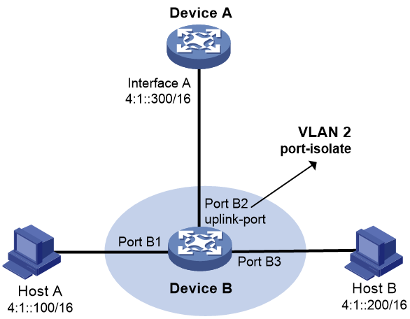
Because Host A's IPv6 address is on the same subnet as Host B's, Host A broadcast an NS message for Host B's MAC address. However, Host B cannot receive the NS message because Port B1 and Port B3 are isolated from each other.
To solve this problem, enable local ND proxy on Interface A of Device A so that Device A can forward messages between Host A and Host B.
Restrictions and guidelines
Local ND proxy implements Layer 3 communication for two hosts in the following cases:
· The two hosts connect to ports of the same device and the ports must be in different VLANs.
· The two hosts connect to isolated Layer 2 ports in the same isolation group of a VLAN.
· If super VLAN is used, the two hosts must belong to different sub VLANs.
Procedure
system-view
2. Enter interface view.
interface interface-type interface-number
3. Enable local ND proxy.
local-proxy-nd enable
By default, local ND proxy is disabled.
Enabling inter-VLAN ND proxy
About this task
As shown in Figure 11, Host A belongs to VLAN 2 and Host B belongs to VLAN 3. Host A and Host B connect to Port B1 and Port B3, respectively. Device B connects to Layer 3 subinterface Interface A.1 on Device A. Interface A.1 is enabled with VLAN termination.
Figure 11 Application environment of inter-VLAN ND proxy
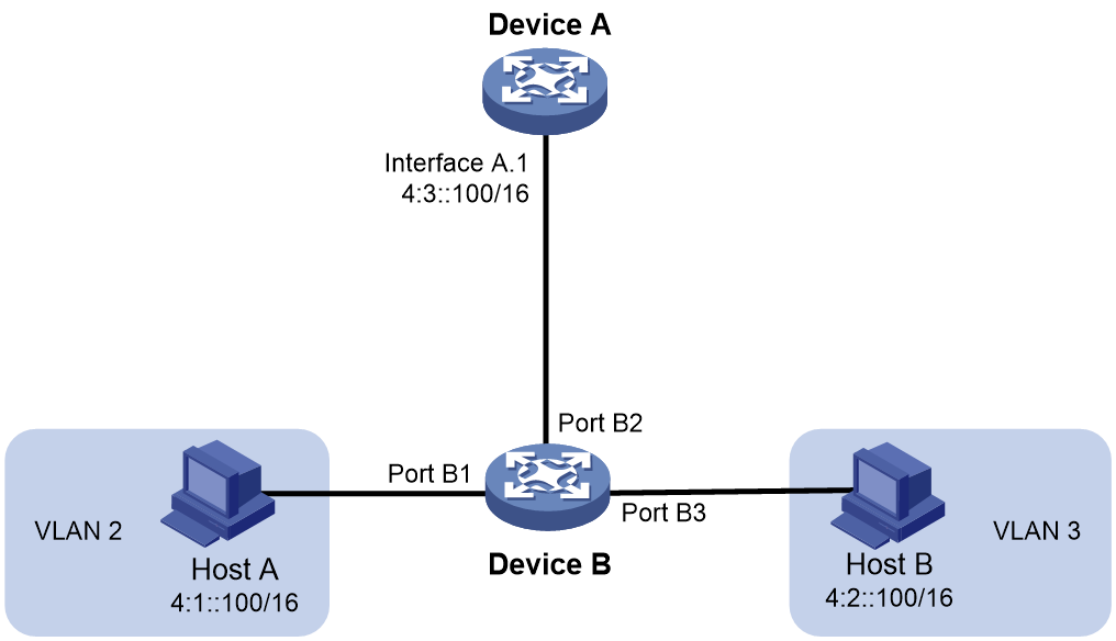
Because Host A's IPv6 address is on the same subnet as Host B's, Host A broadcasts an NS message for Host B's MAC address. However, Host B cannot receive the NS message because they belong to different VLANs.
To solve this problem, enable inter-VLAN ND proxy on Interface A.1 of Device A. The communication process is as follows:
1. Upon receiving the NS message from Host A, Device A searches for the ND entry of Host B.
2. If the entry does not exist, Device A broadcasts an NS message for Host B's MAC address in all VLANs of which the packets are terminated on Interface A.1. After receiving the NS message, Host B sends its MAC address to Device A.
If the entry exists, Device A skips this step.
3. Device A determines whether Host A and Host B are in the same VLAN based on their ND entries.
¡ If they are in the same VLAN, Device A does not reply to the NS message from Host A.
¡ If they are in different VLANs, Device A replies to the NS message with its own MAC address. Host A uses Device A's MAC address to encapsulate the packet destined for Host B. After receiving the packet, Device A forwards the packet to Host B.
Procedure
1. Enter system view.
system-view
2. Enter interface view.
interface interface-type interface-number
3. Enable inter-VLAN ND proxy.
proxy-nd inter-vlan enable
By default, inter-VLAN ND proxy is disabled.
Configuring IPv6 ND direct route advertisement
About IPv6 ND direct route advertisement
The ND direct route advertisement feature generates host routes based on ND entries for packet forwarding and route advertisement.
Application in Layer 3 access networks
As shown in Figure 12, ND direct route advertisement is enabled on Interface A and Interface B. This feature generates a host route to Server A and a host route to Server B for the routing protocols to advertise. So each device forwards only the traffic destined to the server within the network, which saves bandwidth.
Figure 12 Application on a Layer 3 access network
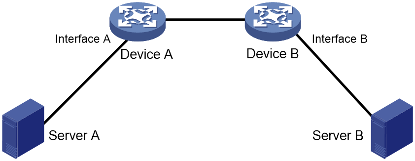
Application in L2VPN access to L3VPN networks
This feature is typically configured on PE-aggs to advertise host routes to PEs in the L3VPN.
As shown in Figure 13, the PE in the L3VPN has ECMP routes destined to a base station in the L2VPN. Traffic from the PE in the L3VPN to the base station can be load shared by PE-agg 1 and PE-agg 2. If PE-agg 1 fails, the PE uses the host route through PE-agg 2 to forward traffic.
Figure 13 Application in an L2VPN access to L3VPN network
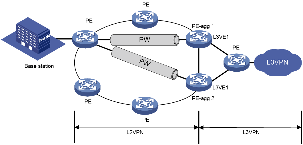
Restrictions and guidelines
This feature takes effect on an interface when you perform one of the following tasks:
· Enable this feature on the interface.
· Enable this feature in system view if the interface is on the public network. This feature takes effect on all interfaces that belong to the public network on the device.
· Enable this feature in VPN instance view if the interface is bound to the VPN instance. This feature takes effect on all interfaces bound to this VPN instance.
To disable this feature on an interface, make sure both of the following requirements are met:
· This feature is disabled on the interface.
· This feature is disabled for the VPN instance or public network to which the interface belongs.
Procedure
1. Enter system view.
system-view
2. Enable ND direct route advertisement.
¡ Enable ND direct route advertisement in system view.
ipv6 nd route-direct advertise
¡ Execute the following commands in sequence to enable ND direct route advertisement in interface view.
interface interface-type interface-number
ipv6 nd route-direct advertise
¡ Execute the following commands in sequence to enable ND direct route advertisement in VPN instance view.
ip vpn-instance vpn-instance-name
ipv6 nd route-direct advertise
By default, ND direct route advertisement is disabled.
Enabling recording user IPv6 address conflicts
About this task
This feature detects and records user IPv6 address conflicts. A conflict occurs if an incoming NA packet has the same source IPv6 address as an existing ND entry but a different source MAC address. The device generates a user IPv6 address conflict record, logs the conflict, and sends the log message to the information center. For log messages to be sent correctly, configure the information center to set log message filtering and output rules, including output destinations. For information about the log destination and output rule configuration in the information center, see the information center in Network Management and Monitoring Configuration Guide.
If you enable user IPv6 address conflict notifications for the ND module, the device sends a notification to the SNMP module when a user IP address conflict occurs. The notification includes the source IPv6 and MAC addresses in the conflicted ND packet, and the MAC address in the conflicted local entry.
For ND event notifications to be sent correctly, you must also configure SNMP on the device. For more information about SNMP configuration, see SNMP configuration in Network Management and Monitoring Configuration Guide. For more information about ND event notifications, see ND attack defense configuration in Security Configuration Guide.
Procedure
1. Enter system view.
system-view
2. (Optional.) Enable SNMP notifications for ND.
snmp-agent trap enable nd [ user-ip-conflict ]
By default, SNMP notifications are disabled for ND.
3. Enable recording user IPv6 address conflicts.
ipv6 nd user-ip-conflict record enable
By default, recording user IPv6 address conflicts is disabled.
Enabling recording ND entry learning events
About this task
An ND entry learning event occurs when the number of ND entries that a card or an interface has learnt exceeds the threshold or drops below the threshold.
After you enable this feature, the ND module logs ND entry learning events and sends them to the information center. For log messages to be sent correctly, configure the information center to set log message filtering and output rules, including output destinations. For information about the log destination and output rule configuration in the information center, see information center configuration in Network Management and Monitoring Configuration Guide.
If you enable ND entry limit notifications for the ND module, the device sends a notification to the SNMP module when the number of ND entries exceeds the alarm threshold. For ND entry limit notifications to be sent correctly, you must also configure SNMP on the device.
For more information about SNMP configuration, see SNMP configuration in Network Management and Monitoring Configuration Guide. For more information about ND entry limit notifications, see ND attack defense configuration in Security Configuration Guide.
Procedure
1. Enter system view.
system-view
2. (Optional.) Enable SNMP notifications for ND.
snmp-agent trap enable nd [ entry-limit ]
By default, SNMP notifications are disabled for ND.
If you do not specify a keyword, this command enable all types of SNMP notifications for ND.
3. Enable recording ND entry learning events.
ipv6 nd entry-limit record enable
By default, the ND module does not record ND entry learning events.
Enabling recording IP address conflicts between the local device and endpoints
About this task
After you enable this feature, the ND module compares the IP address of the sender with the IP address of the local device when it receives an ND packet. If the two IP addresses are the same, the ND module determines that the local device has an address conflict with the sender, and then performs the following tasks:
· Generates an address conflict entry. If the address conflict does not occur again in three minutes, the system will delete the address conflict entry.
· Logs the address conflict and sends the log message to the information center.
For log messages to be sent correctly, configure the information center to set log message filtering and output rules, including output destinations. For information about the log destination and output rule configuration in the information center, see information center configuration in Network Management and Monitoring Configuration Guide.
If you enable SNMP notifications of IP address conflicts between the local device and endpoints, the device sends a notification to the SNMP module when an IP address conflict occurs between the local device and an endpoint. The notification includes the source IPv6 address, source MAC address, destination IPv6 address, and destination MAC address in the conflicted ND packet. For SNMP notifications to be sent correctly, you must also configure SNMP on the device.
For more information about SNMP configuration, see SNMP configuration in Network Management and Monitoring Configuration Guide. For more information about SNMP notifications of endpoint and local device conflicts, see ND attack defense configuration in Security Configuration Guide.
Restrictions and guidelines
An interface sends address conflict log messages to the information center only once per minute.
A maximum of 128 interfaces can send address conflict log messages concurrently to the information center. If the number of interfaces exceeds 128, the excess interfaces cannot send address conflict log messages to the information center unless some of the prior 128 interfaces have no address conflict.
Procedure
1. Enter system view.
system-view
2. (Optional.) Enable SNMP notifications for ND.
snmp-agent trap enable nd [ local-conflict ]
By default, SNMP notifications are disabled for ND.
If you do not specify a keyword, this command enable all types of SNMP notifications for ND.
3. Enable recording IP address conflicts between the local device and endpoints.
ipv6 nd local-conflict record enable
By default, the ND module does not record IP address conflicts between the local device and endpoints.
Enabling recording overspeed events of ND Miss message generation and ND packet sending
About this task
When the device receives an IPv6 Layer 3 packet that cannot match any host route but a network route, it performs the following task:
1. Generates an ND Miss message and delivers the packet to its CPU for processing.
2. Sends an NS packet to the destination network read from the packet.
A large number of ND Miss messages indicate that the device has many packets that cannot be forwarded smoothly.
To resolve this issue, enable the ND module to record overspeed events of ND Miss message generation and ND packet sending. The ND module sends the log messages to the information center. For log messages to be sent correctly, configure the information center to set log message filtering and output rules, including output destinations. For information about the log destination and output rule configuration in the information center, see information center configuration in Network Management and Monitoring Configuration Guide.
|
|
NOTE: The alarm threshold on the speed of ND Miss message generation varies by device model. The ND packet sending rate is a fixed value in the current software version. To avoid frequent alarms and alarm clearance, the system will not send an alarm again in one minute after the alarm is cleared. |
For log messages to be sent correctly, configure the information center to set log message filtering and output rules, including output destinations. For information about the log destination and output rule configuration in the information center, see information center configuration in Network Management and Monitoring Configuration Guide.
You can enable sending rate limit notifications for ND Miss messages or ND packets. The device then sends the peak sending rate in a notification to the SNMP module when the number of ND Miss messages or ND packets sent per second exceeds the alarm threshold. For SNMP notifications to be sent correctly, you must also configure SNMP on the device.
For more information about SNMP configuration, see SNMP configuration in Network Management and Monitoring Configuration Guide. For more information about sending rate limit notifications for ND Miss messages or ND packets, see ND attack defense configuration in Security Configuration Guide.
Restrictions and guidelines
An interface sends address conflict log messages to the information center only once per minute.
A maximum of 128 interfaces can send address conflict log messages concurrently to the information center. If the number of interfaces exceeds 128, the excess interfaces cannot send address conflict log messages to the information center unless some of the prior 128 interfaces have no address conflict.
Procedure
1. Enter system view.
system-view
2. (Optional.) Enable SNMP notifications for ND.
snmp-agent trap enable nd [ nd-miss ]
By default, SNMP notifications are disabled for ND.
If you do not specify a keyword, this command enable all types of SNMP notifications for ND.
3. Enable recording overspeed events of ND Miss message generation and ND packet sending.
ipv6 nd nd-miss record enable
By default, the ND module does not record overspeed events of ND Miss message generation and ND packet sending.
Display and maintenance commands for IPv6 ND
Execute display commands in any view and reset commands in user view.
|
Task |
Command |
|
Display user IPv6 address conflict records. |
display ipv6 nd user-ip-conflict record [slot slot-number ] |
|
Display neighbor information. |
display ipv6 neighbors { { ipv6-address | all | dynamic | static } [ slot slot-number ] | interface interface-type interface-number | vlan vlan-id } [ verbose ] |
|
Display the total number of neighbor entries. |
display ipv6 neighbors { { all | dynamic | static } [ slot slot-number ] | interface interface-type interface-number | vlan vlan-id } count |
|
Display the maximum number of ND entries that a device supports. |
display ipv6 neighbors entry-limit |
|
Display neighbor information for a VPN. |
display ipv6 neighbors vpn-instance vpn-instance-name [ count ] |
|
Clear IPv6 neighbor information. |
reset ipv6 neighbors { all | dynamic | interface interface-type interface-number | slot slot-number | static } |
