- Table of Contents
- Related Documents
-
| Title | Size | Download |
|---|---|---|
| 01-SDWAN configuration | 404.66 KB |
BGP IPv4 tunnel-encap-ext address family
SDWAN tunnel establishment with NAT traversal
Configuring site and device identification information
Specifying a site for the device
Specifying an ID and system IP address for the device
Configuring BGP to advertise IPv4 tunnel-encap-ext routes
Restrictions and guidelines for BGP IPv4 tunnel-encap-ext route advertisement
Enabling BGP to advertise BGP IPv4 tunnel-encap-ext routes
Configuring BGP IPv4 tunnel-encap-ext route settings
Using BGP EVPN IP prefix advertisement routes to advertise routes for a VPN instance
Display and maintenance commands for SDWAN
SDWAN overview
About SDWAN
Software-defined WAN (SDWAN) is a VPN technology that applies SDN technologies to WAN. The control plane uses SSL and MP-BGP to advertise transport tunnel endpoint (TTE) information to set up SDWAN tunnels between sites and uses MP-BGP to advertise private routes between sites. The data plane uses UDP to encapsulate and forward data packets and uses security mechanisms such as IPsec to secure data transmission. SDWAN provides secure and reliable interconnection services for geographically dispersed enterprise networks and data centers.
SDWAN network model
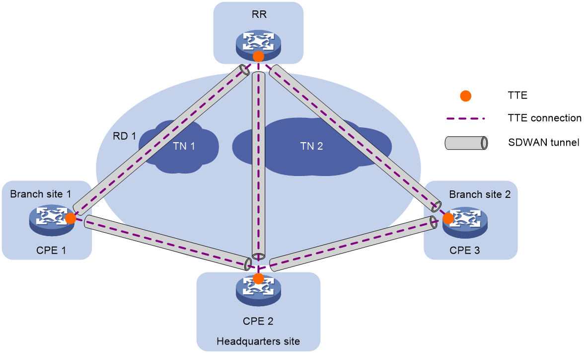
As shown in Figure 1, SDWAN contains the following components:
· Customer provided edge (CPE)—Edge device at a customer site.
· Route reflector (RR)—Used to reflect TTE information and private routes between CPEs.
· Transport network (TN)—Service provider WAN that connects sites. A transport network can be a service provider VPN or the Internet public network. A transport network is identified by its transport network ID or name. Transport networks are the fundamentals to construct SDWAN overlay network.
· Routing domain (RD)—Domain that contains transport networks that are reachable at Layer 3. SDWAN tunnels can be established only between CPEs or between CPEs and RRs in the same routing domain.
· Site ID—A site ID is a string of digits used to uniquely identify a site in the SDWAN network. The network controller allocates site IDs to all sites.
· Device ID—A device ID uniquely identifies an SDWAN-capable device (or SDWAN device) at a site. Typically, a site contains one or two SDWAN devices.
· SDWAN tunnel—Point-to-multipoint logical channel established among SDWAN devices. One site transmits traffic to another site over an SDWAN tunnel.
· Secure Sockets Layer (SSL) connection—In the SDWAN network, a CPE and an RR establish an SSL connection to exchange TTE information for control channel establishment.
· Transport tunnel endpoint (TTE)—Endpoint that connects an SDWAN device to a transport network and endpoint of an SDWAN tunnel. Device TTE information includes the site ID, transport network ID (TN ID), private IP address, public IP address, and tunnel encapsulation mode.
· TTE connection—Point-to-point logical connection established between TTEs. An SDWAN tunnel can hold multiple TTE connections.
SDWAN packet formats
SDWAN supports control packets and data packets.
· SDWAN control packets are used for NAT traversal. The device uses SDWAN control packets to advertise its public IP address translated after NAT to remote devices. For more information about NAT traversal, see "SDWAN tunnel establishment with NAT traversal."
· SDWAN data packets are used to forward user packets.
Control packet format
As shown in Figure 2, an SDWAN control packet contains the following components:
· Data portion.
· IPsec header (optional).
· 12-byte SDWAN header.
· 8-byte outer UDP header. The destination port number in the UDP header is the SDWAN UDP port number. By default, the port number is 4799.
· 20-byte outer IP header.
The SDWAN header contains the following fields:
· Type—Type of the packet. The length for this field is 8 bits. For an SDWAN control packet, the value is 1.
· Subtype—Subtype of the control packet. The length for this field is 8 bits. If the value is 1, the packet is a NAT address probe request packet.
· Version—Version number of SDWAN protocol packets. The value is fixed at 0.
· Reserved—Reserved field. The value is fixed at 0.
· Length—Length of the SDWAN header. The length for this field is 16 bits. The value is fixed at 12 in the current software version.
· TTE ID—Identifies a TTE. The length for this field is 32 bits.
Figure 2 SDWAN control packet format

Data packet format
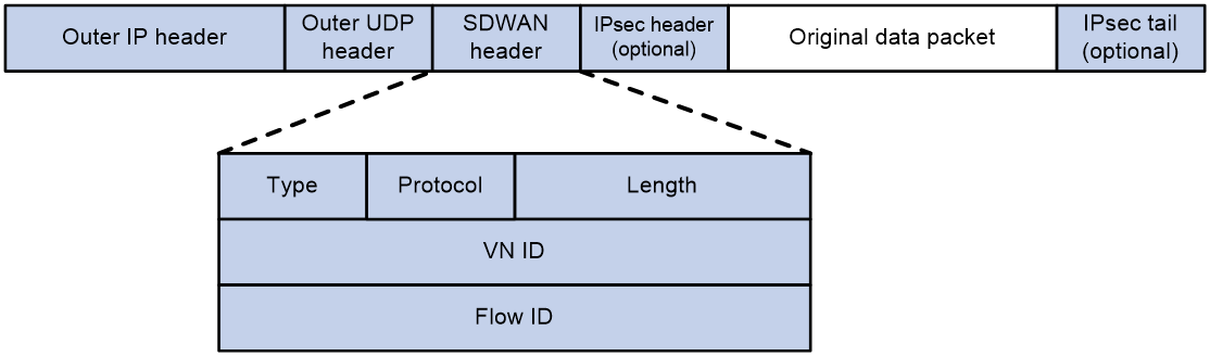
As shown in Figure 3, an SDWAN data packet contains the following components:
· Original data packet.
· IPsec header (optional).
· 12-byte SDWAN header.
· 8-byte outer UDP header. The destination port number in the UDP header is the SDWAN UDP port number. By default, the port number is 4799.
· 20-byte outer IP header.
The SDWAN header contains the following fields:
· Type—Type of the packet. The length for this field is 8 bits. For an SDWAN data packet, the value is 2.
· Protocol—Type of the inner data packet. The length for this field is 8 bits. If the value is 1, the packet is an IPv4 packet. If the value is 2, the packet is an IPv6 packet.
· Length—Length of the SDWAN header. The length for this field is 16 bits. The value is fixed at 12 in the current software version.
· VN ID—VN ID of the VPN instance to which the SDWAN data packet belongs. The length for this field is 32 bits. If the packet belongs to the public instance, the value for this field is all zeros.
· Flow ID—Flow ID of the SDWAN data packet. The length for this field is 32 bits. To mark packets with a flow ID, use the remark flow-id command. If no flow ID is marked, the value for this field is all zeros. For more information about the remark flow-id command, see QoS commands in ACL and QoS Command Reference.
Figure 3 SDWAN data packet format
BGP extensions
BGP IPv4 tunnel-encap-ext address family
To support SDWAN, BGP defines a new address family called BGP IPv4 tunnel-encap-ext address family. This address family is a subsequent address family of the IPv4 address family. The subsequent address family identifier (SAFI) is 74. Routes exchanged under this address family are IPv4 tunnel-encap-ext routes. IPv4 tunnel-encap-ext routes can include the following information in the Multiprotocol Reachable NLRI (MP_REACH_NLRI) attribute:
· TTE information—Includes site ID, transport network ID, public IP address, private IP address, and tunnel encapsulation mode. CPEs use the information to set up data channels between each other.
· SaaS path quality information—Includes link delay, jitter, packet loss ratio, and CQI. RIR uses the information to select the optimal path for application traffic.
Figure 4 MP_REACH_NLRI attribute in IPv4 tunnel-encap-ext routes
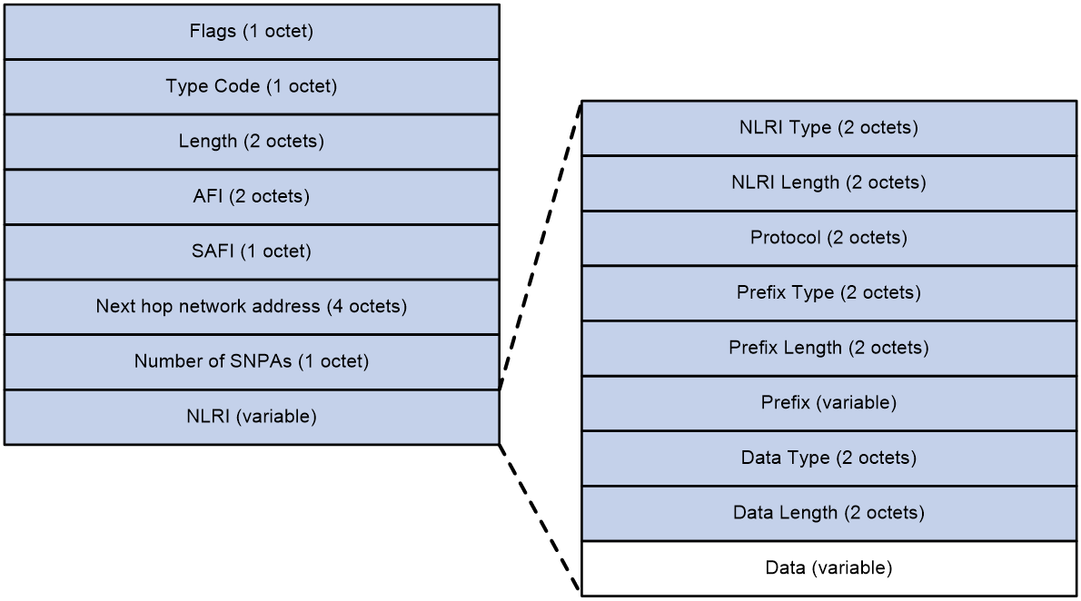
As shown in Figure 4, the MP_REACH_NLRI attribute in IPv4 tunnel-encap-ext routes contains the following fields:
· Flags—BGP attribute flags. The value is 0x90, which indicates that this attribute is an optional nontransitive attribute that includes complete information.
· Type Code—BGP attribute type. The value is 14.
· Length—Length of the MP_REACH_NLRI attribute.
· AFI—Address family identifier. The value is 1, which represents IPv4 address family.
· SAFI—Subsequent address family identifier. The value is 74, which represents IPv4 tunnel-encap-ext address family.
· Next hop network address—Next hop IP address.
· Number of SNPAs—Number of Subnetwork Point of Attachments (SNPAs) in the subsequent field. If the value is 0, the attribute does not include an SNPA.
· NLRI—Network layer reachability information.
Network layer reachability information in the MP_REACH_NLRI attribute includes the following fields:
· NLRI Type—Type of NLRI. If the value is 1, this field includes TTE information. If the value is 2, this field includes SaaS path quality information.
· NLRI Length—Length of NLRI.
· Protocol—Protocol stack of NLRI. The value is 2, which represents IPv4 protocol stack.
· Prefix Type—Prefix type of NLRI. The value is 1.
· Prefix Length—Prefix length of NLRI.
· Prefix—Prefix information of NLRI. For TTE information, the value is the TTE ID. For SaaS path quality information, the value is the site ID and device ID.
· Data Type—Type of the data portion in NLRI. The value is 2.
· Data Length—Length of the data portion in NLRI.
· Data—Data portion in NLRI. This field includes detailed TTE information or SaaS path quality information.
BGP EVPN routes
You can deploy SDWAN across VPNs. A CPE advertises VPN routes to other CPEs in the format of BGP EVPN IP prefix advertisement routes. To support SDWAN, the following extensions are added to BGP EVPN routes:
· SDWAN encapsulation is added to the TUNNEL_ENCAPSULATION_ATTRIBUTE attribute. SDWAN-encapsulated IP prefix advertisement routes can be forwarded only between the devices that are enabled to advertise BGP EVPN routes in SDWAN encapsulation.
· A VN ID is added to the NLRI field of IP prefix advertisement routes. The VN ID is used to differentiate private routes in different VPN instances.
Channel establishment
As shown in Figure 5, an SDWAN network supports control channels and data channels.
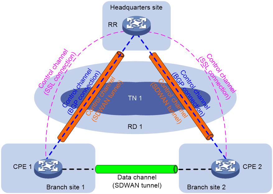
Control channel establishment
A control channel is established between an RR and a CPE to advertise TTE information and private routes. The establishment process is as follows:
1. The CPE and RR establish an SSL connection (control channel). The CPE is the SSL client, also referred to as the SDWAN client. The RR is the SSL server, also referred to as the SDWAN server.
2. The CPE and RR exchange TTE information.
3. After receiving TTE information from each other, the CPE and RR compare the routing domain in the received TTE information with the routing domain in the local TTE information.
¡ If the routing domains are the same one, the CPE and RR establish an SDWAN tunnel (control channel) between them.
¡ If the routing domains are different, the CPE and RR do not establish an SDWAN tunnel between them.
4. The CPE and RR each automatically add the user network routes (UNRs) destined for the system IP address of the peer device to the local routing table.
5. The CPE and RR establish a BGP connection (control channel) under the IPv4 tunnel-encap-ext address family based on their system IP addresses.
Data channel establishment
A data channel is established between two CPEs to transmit data packets. The establishment process is as follows:
1. The CPEs use IPv4 tunnel-encap-ext routes to advertise TTE information to an RR.
2. The RR reflects the TTE information of each CPE to the other CPE.
3. When each CPE receives TTE information reflected by the RR, they compare the routing domain in the TTE information with the routing domain in the local TTE information.
¡ If the routing domains are the same one, the CPEs establish an SDWAN tunnel between them.
¡ If the routing domains are different, the CPEs do not establish an SDWAN tunnel between them.
To secure data transmission, use IPsec to encrypt data packets.
Route advertisement
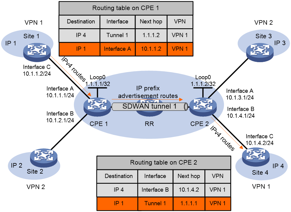
As shown in Figure 6, inter-site route advertisement in an SDWAN network includes the following processes:
1. Each site advertises private routes to its local CPE.
2. CPEs advertise routes to each other.
3. Each CPE advertises private routes received from another site to its local site.
Then, the sites have routes to reach one another.
Advertising private routes from local site to local CPE
The local site uses static routing, RIP, OSPF, IS-IS, EBGP, or IBGP to advertise the private routes of the local site to the local CPE. The routes are standard IPv4 routes.
Advertising routes from local CPE to remote CPEs
1. When the local CPE learns private routes from the local site, it stores the routes to the routing table of the corresponding VPN instance.
2. The CPE adds RD and export targets to the standard IPv4 routes, converts the routes to BGP EVPN IP prefix advertisement routes, and advertises the routes to an RR. The next hop address of the routes is the system IP address of the local CPE.
3. The RR reflects the received IP prefix advertisement routes to remote CPEs.
4. When a remote CPE receives the IP prefix advertisement routes reflected by the RR, it matches the export targets in the IP prefix advertisement routes with the import targets of local VPN instances. If a matching VPN instance is found, the remote CPE accepts the IP prefix advertisement routes and adds the routes to the routing table of the VPN instance.
Advertising routes from remote CPEs to remote sites
The supported routing methods are the same as the routing methods for advertising routes from the local site to the local CPE. A remote site can use multiple methods to learn private routes from its CPE. The methods include static routing, RIP, OSPF, IS-IS, EBGP, and IBGP.
Traffic forwarding
In an SDWAN network, when a CPE receives a customer packet, it looks up the routing table for the output interface and next hop based on the destination IP address of the packet. The CPE forwards the packet differently according to the output interface.
· If the output interface is a local interface on the CPE, the CPE directly forwards the packet out of the interface to the next hop according to the forwarding table.
· If the output interface is an SDWAN tunnel interface, the CPE forwards the packet as follows:
a. Obtains the TTE ID of the next hop address according to the next hop address in the forwarding table.
b. Obtains TTE connection information based on the TTE IDs of the local device and next hop.
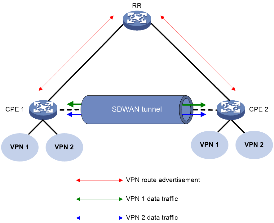
c. Adds SDWAN encapsulation to the packet according to the TTE connection information. The SDWAN header includes the VN ID of the VPN instance to which the data packet belongs. Packets of different VPN instances can be recursed to the same SDWAN tunnel. In this case, the VN ID in the SDWAN header is used to differentiate the VPN instances, as shown in Figure 7.
d. Forwards the packet out of the physical output interface bound to the SDWAN tunnel.
When the remote CPE receives and decapsulates the SDWAN packet, it looks up the routing table of the matching VPN instance according to the VN ID and forwards the packet.
Figure 7 SDWAN traffic forwarding
IPsec-protected SDWAN tunnels
To ensure confidentiality and integrity for data transmitted over SDWAN tunnels, the device supports using IPsec to protect SDWAN packets. For this purpose, the following extensions are added to IPsec:
· SDWAN IPsec profile.
· Sharing a pair of IPsec SAs among multiple SDWAN tunnels.
For more information about IPsec, see Security Configuration Guide.
SDWAN tunnel establishment with NAT traversal
About this feature
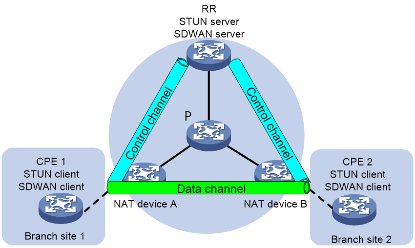
As shown in Figure 8, users at branch sites use private IP addresses so as to conserve IP address resources. After NAT devices translate the private IP addresses to public IP addresses, users at one branch site can access other sites.
IP addresses of the packets sent by a CPE will change after the packets pass through a NAT device. If the CPE cannot obtain its public IP address translated after NAT, it cannot establish an SDWAN tunnel with the other CPE or with the RR. To resolve this issue, configure Session Traversal Utilities for NAT (STUN) in the SDWAN network. For more information about STUN, see Layer 3—IP Services Configuration Guide.
STUN uses the client/server model. Typically, use CPEs as STUN clients and use the RR as the STUN server. The clients exchange packets with the server to identify whether NAT devices exist in the SDWAN network. If NAT devices exist, the clients obtain their public IP addresses and port numbers translated after NAT.
After a CPE (STUN client) obtains its public IP address and port number translated after NAT, it uses this public IP address to establish an SDWAN tunnel with the other CPE. If two CPEs cannot establish a direct data channel between them, you must deploy a NAT transfer on the transport network for the CPEs to communicate with each other.
Figure 8 SDWAN tunnel establishment with NAT traversal
This following information uses Figure 9 to illustrate the control channel and data channel establishment processes.
Figure 9 SDWAN tunnel establishment with NAT traversal (deployed with a NAT transfer)

Control channel establishment
As shown in Figure 9, control channels are established in the following process:
1. The STUN clients and STUN server exchange STUN protocol packets. Each STUN client obtains the local NAT type, public IP address (public IP address translated after NAT when the STUN client accesses the STUN server), and port number.
2. The SDWAN clients and SDWAN server establish SSL connections. Then, they exchange TTE information, including the NAT type and public IP addresses obtained through STUN.
3. When CPE 1, CPE 2, and the NAT transfer receive TTE information from the RR, they compare the routing domain in the TTE information with the routing domain in the local TTE information. If the routing domains are the same one, they establish SDWAN tunnels destined for the RR. The destination IP address of the tunnels is the public IP address in the TTE information of the RR. If the routing domains are different, they do not establish SDWAN tunnels.
If the NAT transfer belongs to the public network, the RR establishes an SDWAN tunnel destined for the public IP address of the NAT transfer. The public IP address is the public IP address in the TTE information of the NAT transfer.
If the NAT type in the TTE information of CPE 1 and CPE 2 is full cone NAT, the RR establishes SDWAN tunnels destined for the public IP addresses of the CPEs. The public IP addresses are the public IP addresses in the TTE information of the CPEs.
If the NAT type in the TTE information of CPE 1 and CPE 2 is port restricted full cone NAT, restricted full cone NAT, or symmetric NAT, the RR cannot access CPE 1 or CPE 2 through the public IP addresses of the CPEs in the TTE information. The RR cannot establish SDWAN tunnels to the CPEs according to the currently obtained TTE information. To establish SDWAN tunnels from the RR to the CPEs:
5. After SDWAN tunnel establishment, CPE 1, CPE 2, the NAT transfer, and the RR add user network routes (UNRs) destined for the system IP addresses of peer devices.
6. CPE 1, CPE 2, the NAT transfer, and the RR establish BGP connections (control channels) under the IPv4 tunnel-encap-ext address family based on the system IP addresses.
Data channel establishment
As shown in Figure 9, data channels are established in the following process:
1. After CPE 1, CPE 2, the NAT transfer, and the RR establish BGP connections (control channels), CPE 1, CPE 2, and the NAT transfer advertise TTE information to the RR through IPv4 tunnel-encap-ext routes. The RR reflects the TTE information to its BGP neighbors.
2. The CPEs establish data channels. In addition to that the routing domain must be the same, whether two CPEs can establish a data channel depends on their NAT types. Table 1 shows the data channel compatibility for different NAT types.
¡ If the CPEs can establish a direct data channel, the establishment procedure is the same as step 4 in "Control channel establishment."
¡ If the CPEs cannot establish a direct data channel, you must deploy a NAT transfer in the network. The CPEs each establish a data channel to the NAT transfer. Inter-CPE data is first forwarded to the NAT transfer through a data channel. Then, the NAT transfer forwards the data to the destination CPE through the other data channel. The procedure for establishing a data channel between a CPE and the NAT transfer is the same as that for establishing an SDWAN tunnel between a CPE and an RR. For more information, see step 4 in "Control channel establishment."
Table 1 Data channel compatibility for different NAT types
|
CPE 1 NAT type |
CPE 2 NAT type |
Support for CPE-CPE direct tunnels |
NAT transfer required for CPE intercommunication |
|
Non-NAT |
Full cone NAT |
√ |
× |
|
Non-NAT |
Port restricted full cone NAT or restricted full cone NAT |
√ |
× |
|
Non-NAT |
Symmetric NAT |
√ |
× |
|
Non-NAT |
Unknown type |
√ |
× |
|
Full cone NAT |
Full cone NAT |
√ |
× |
|
Full cone NAT |
Port restricted full cone NAT or restricted full cone NAT |
√ |
× |
|
Full cone NAT |
Symmetric NAT |
√ |
× |
|
Full cone NAT |
Unknown type |
√ |
× |
|
Port restricted full cone NAT or restricted full cone NAT |
Port restricted full cone NAT or restricted full cone NAT |
√ |
× |
|
Port restricted full cone NAT or restricted full cone NAT |
Symmetric NAT |
× |
√ |
|
Port restricted full cone NAT or restricted full cone NAT |
Unknown type |
× |
√ |
|
Symmetric NAT |
Symmetric NAT |
× |
√ |
|
Symmetric NAT |
Unknown type |
× |
√ |
|
Unknown type |
Unknown type |
× |
√ |
Configuring SDWAN
SDWAN tasks at a glance
To configure SDWAN, perform the following tasks:
1. Configuring site and device identification information
a. Specifying a site for the device
b. Specifying an ID and system IP address for the device
2. Configuring an SDWAN client
3. Configuring an SDWAN server
4. (Optional.) Configuring IPsec-protected SDWAN tunnels
For more information, see IPsec in Security Configuration Guide.
5. (Optional.) Configuring SDWAN tunnels with NAT traversal
For more information, see NAT in Layer 3—IP Services Configuration Guide.
6. Configuring an SDWAN tunnel
7. Configuring BGP to advertise IPv4 tunnel-encap-ext routes
8. Using BGP EVPN IP prefix advertisement routes to advertise routes for a VPN instance
Configuring site and device identification information
Specifying a site for the device
About this task
A site ID uniquely identifies a site in an SDWAN network.
You can specify a site name for a site to describe the site location and function to better identify the site in the SDWAN network. A site name does not uniquely identify a site. You can specify the same name for multiple devices.
Restrictions and guidelines
Different site roles have different functions. A site role change will cause SDWAN tunnel flapping and interrupt ongoing services. As a best practice, complete role configuration before the SDWAN network runs services.
Procedure
1. Enter system view.
system-view
2. Specify the ID of the site to which the device belongs.
sdwan site-id site-id
By default, no site ID is specified for the device.
3. Specify the name of the site to which the device belongs.
sdwan site-name site-name
By default, no site name is specified for the device.
4. Specify the role of the site to which the device belongs.
sdwan site-role { cpe | nat-transfer | rr } *
By default, no site role is specified for the device.
All SDWAN devices at the same site must be assigned the same site role.
Specifying an ID and system IP address for the device
About this task
A device ID uniquely identifies a device at a site.
The device uses the system IP address to set up BGP sessions with other devices. In an RIR scenario, the system IP address is also used as the inner destination IP address of probe packets sent by the NQA client in NQA link connectivity probes. For more information about RIR, see Layer 3—IP Routing Configuration Guide.
Procedure
1. Enter system view.
system-view
2. Assign an ID to the device.
sdwan device-id device-id
By default, no ID is assigned to the device.
3. Specify a system IP address for the device.
sdwan system-ip interface-type interface-number
By default, no system IP address is specified for the device.
The system IP address must be unique in the SDWAN network.
For this command to take effect, you must specify a loopback interface that has an IP address.
Configuring an SDWAN client
About this task
In an SDWAN network, the CPEs, NAT transfer, and RRs exchange TTE information through SSL connections. The CPEs and NAT transfer act as SDWAN clients and the RRs act as SDWAN servers.
Perform this task to specify an SSL client policy on a CPE or the NAT transfer for the CPE or NAT transfer to establish SSL connections with RRs. After SSL connection establishment, the CPE or NAT transfer advertises its local TTE information to RRs. The RRs advertise their local TTE information to the CPE or NAT transfer. After TTE information exchange, the CPE or NAT transfer can establish SDWAN tunnels to the RRs.
Restrictions and guidelines
Only one SSL client policy can be applied to an SSL connection. If you execute the sdwan ssl-client-policy command multiple times, the most recent configuration takes effect and it takes effect only on SSL connections established after the modification.
Prerequisites
Complete the SSL client policy settings. For more information about SSL client policies, see SSL configuration in Security Configuration Guide.
Procedure
1. Enter system view.
system-view
2. Specify an SDWAN server on the CPE or NAT transfer.
sdwan server system-ip system-ip-address ip ip-address [ port port-number ] [ vpn-instance vpn-instance-name ]
By default, no SDWAN servers are specified on a CPE or the NAT transfer.
3. Specify an SSL client policy on the CPE or NAT transfer for the CPE or NAT transfer to establish SSL connections with RRs (SDWAN servers).
sdwan ssl-client-policy policy-name
By default, no SSL client policy is specified on a CPE or the NAT transfer for the CPE or NAT transfer to establish SSL connections with RRs (SDWAN servers).
Configuring an SDWAN server
About this task
Perform this task to allow an RR to establish SSL connections with CPEs or the NAT transfer and advertise its local TTE information to the CPEs or NAT transfer. The CPEs or NAT transfer also advertise their local TTE information to the RR through the SSL connections. After TTE information exchange, the RR and the CPEs or NAT transfer will establish SDWAN tunnels based on the TTE information.
The device supports the following modes for SSL connection establishment:
· Simple mode—To use this mode, you do not need to specify an SSL server policy on the RR. The RR uses the self-signed certificate and the default settings of the SSL parameters to establish SSL connections with the CPEs or NAT transfer. The configuration for this mode is simple, but this mode is less secure than the secure mode.
· Secure mode—To use this mode, you must specify an SSL server policy on the RR and configure PKI domain settings. The configuration for this mode is complex, but this mode is more secure than the simple mode.
Restrictions and guidelines
Only one SSL server policy can be applied to an SSL connection. If you execute the sdwan ssl-server-policy command multiple times, the most recent configuration cannot take effect automatically. For the configuration to take effect, you must execute the undo sdwan server enable command and then the sdwan server enable command to re-enable the SDWAN server.
Prerequisites
To use the secure mode, first complete the SSL server policy settings. For more information about SSL server policies, see SSL configuration in Security Configuration Guide.
Procedure
1. Enter system view.
system-view
2. Enable SDWAN server on the RR.
sdwan server enable
By default, SDWAN server is disabled on an RR.
3. Specify a TCP port number for the SDWAN server on the RR.
sdwan server port port-number
By default, the TCP port number of the SDWAN server is 2004.
4. Specify an SSL server policy on the RR for the RR to establish SSL connections with CPEs or the NAT transfer (SDWAN clients).
sdwan ssl-server-policy policy-name
By default, no SSL server policy is specified on an RR for the RR to establish SSL connections with CPEs or the NAT transfer.
Configuring an SDWAN tunnel
About this task
After an SDWAN tunnel is established, the local device sends keepalive requests to the remote device over all the TTE connections on the tunnel interface at the specified keepalive interval.
· If the local device receives a keepalive response from the remote device within a keepalive interval, it determines that a TTE connection is reachable to the remote device.
· If the local device cannot receive a keepalive response from the remote device on a TTE connection within a keepalive interval, it resends a keepalive request. If the local device still cannot receive a response within the keepalive interval multiplied by keepalive retries, it determines that the TTE connection is unreachable to the remote device. The device no longer forwards packets through the TTE connection.
Restrictions and guidelines
For information about tunnel configuration and tunnel interface commands, see tunneling in Layer 3—IP Services Configuration Guide.
You can specify a source UDP port number for SDWAN tunneled packets both in system view and in tunnel interface view.
· The source UDP port number specified in system view applies to all SDWAN tunnel interfaces.
· The source UDP port number specified in tunnel interface view applies only to a tunnel interface.
For a tunnel interface, the source UDP port number specified in tunnel interface view takes precedence over that specified in system view. If no source UDP port number is specified in tunnel interface view, the source UDP port number specified in system view applies.
Procedure
1. Enter system view.
system-view
2. (Optional.) Specify a global source UDP port number for SDWAN tunneled packets.
sdwan encapsulation global-udp-port port-number
By default, the global source UDP port number for SDWAN tunneled packets is 4799.
3. Create an IPv4 SDWAN tunnel interface in UDP encapsulation mode and enter tunnel interface view.
interface tunnel tunnel-number mode sdwan udp
For packet tunneling to succeed, the two ends of a tunnel must use the same tunnel mode.
4. Specify a physical output interface for SDWAN tunneled packets.
tunnel out-interface out-interface-type out-interface-number
By default, no output interface is specified for tunneled packets. If ECMP routes exist, the device randomly selects an output interface to forward tunneled packets.
5. Assign an interface ID to the SDWAN tunnel interface.
sdwan interface-id interface-id
By default, no interface ID is assigned to an SDWAN tunnel interface.
6. (Optional.) Specify a source UDP port number for SDWAN tunneled packets.
sdwan encapsulation udp-port port-number
By default, the source UDP port number of SDWAN tunneled packets is the global source UDP port number for SDWAN tunneled packets.
7. Specify a routing domain for the SDWAN tunnel.
sdwan routing-domain domain-name id domain-id
By default, no routing domain is specified for an SDWAN tunnel.
8. Specify a transport network for the SDWAN tunnel.
sdwan transport-network network-name id network-id
By default, no transport network is specified for an SDWAN tunnel.
9. Specify a source IP address for the SDWAN tunnel. Choose one of the following options:
¡ Specify a source IP address for the tunnel.
source { ipv4-address | ipv6-address }
The specified IP address is used as the source address of SDWAN tunneled packets.
¡ Specify a source interface to provide source IP address for the tunnel.
source interface-type interface-number
The IP address of the specified interface is used as the source IP address of SDWAN tunneled packets.
By default, no source IP address is configured for an SDWAN tunnel.
10. (Optional.) Configure keepalive for the SDWAN tunnel.
sdwan keepalive interval interval [ retry retries ]
By default, the keepalive interval is 10 seconds and the number of keepalive retries is 3.
In an RIR-SDWAN network, set the keepalive interval within the range of 1 to 5 seconds as a best practice.
Configuring BGP to advertise IPv4 tunnel-encap-ext routes
Restrictions and guidelines for BGP IPv4 tunnel-encap-ext route advertisement
For more information about BGP commands in this task, see Layer 3—IP Routing Command Reference.
Enabling BGP to advertise BGP IPv4 tunnel-encap-ext routes
1. Enter system view.
system-view
2. Enable a BGP instance and enter BGP instance view.
bgp as-number [ instance instance-name ]
By default, BGP is disabled and no BGP instances exist.
3. Specify a CPE or RR as a peer.
peer { group-name | ipv4-address [ mask-length ] } as-number as-number
4. Create the BGP IPv4 tunnel-encap-ext address family and enter BGP IPv4 tunnel-encap-ext address family view.
address-family ipv4 tnl-encap-ext
5. Enable BGP to exchange BGP IPv4 tunnel-encap-ext routes with a peer or peer group.
peer { group-name | ipv4-address [ mask-length ] } enable
By default, BGP does not exchange BGP IPv4 tunnel-encap-ext routes with peers or peer groups.
Configuring BGP IPv4 tunnel-encap-ext route settings
Controlling BGP IPv4 tunnel-encap-ext route advertisement and reception
1. Enter system view.
system-view
2. Enter BGP instance view
bgp as-number [ instance instance-name ]
3. Enter BGP IPv4 tunnel-encap-ext address family view.
address-family ipv4 tnl-encap-ext
4. Apply a routing policy to routes received from or advertised to a peer or peer group.
peer { group-name | ipv4-address [ mask-length ] } route-policy route-policy-name { export | import }
By default, no routing policies are applied to routes received from or advertised to peers or peer groups.
5. Set the maximum number of routes that can be received from a peer or peer group.
peer { group-name | ipv4-address [ mask-length ] } route-limit prefix-number [ { alert-only | discard | reconnect reconnect-time } | percentage-value ] *
By default, the number of routes that can be received from a peer or peer group is not limited.
Configuring BGP IPv4 tunnel-encap-ext route attributes
1. Enter system view.
system-view
2. Enter BGP instance view.
bgp as-number [ instance instance-name ]
3. Enter BGP IPv4 tunnel-encap-ext address family view.
address-family ipv4 tnl-encap-ext
4. Set the local router as the next hop for routes advertised to a peer or peer group.
peer { group-name | ipv4-address [ mask-length ] } next-hop-local
The default settings are as follows:
¡ BGP sets the local router as the next hop for all routes advertised to an EBGP peer or peer group.
¡ BGP does not set the local router as the next hop for EBGP routes advertised to an IBGP peer or peer group.
5. Set a preferred value for routes received from a peer or peer group
peer { group-name | ipv4-address [ mask-length ] } preferred-value value
By default, the preferred value is 0 for routes received from a peer or peer group.
6. Permit the local AS number to appear in routes from a peer or peer group and set the number of appearances.
peer { group-name | ipv4-address [ mask-length ] } allow-as-loop [ number ]
By default, the local AS number is not allowed in routes from peers.
Configuring BGP route reflection
1. Enter system view.
system-view
2. Enter BGP instance view.
bgp as-number [ instance instance-name ]
3. Enter BGP IPv4 tunnel-encap-ext address family view.
address-family ipv4 tnl-encap-ext
4. Configure the device as an RR and specify a CPE or NAT device as its client.
peer { group-name | ipv4-address [ mask-length ] } reflect-client
By default, no RR or clients are configured.
5. (Optional.) Enable BGP IPv4 tunnel-encap-ext route reflection between clients.
reflect between-clients
By default, BGP IPv4 tunnel-encap-ext route reflection between clients is enabled.
6. (Optional.) Configure the cluster ID of the RR.
reflector cluster-id { cluster-id | ipv4-address }
By default, an RR uses its own router ID as the cluster ID.
Configuring community attributes
1. Enter system view.
system-view
2. Enter BGP instance view.
bgp as-number [ instance instance-name ]
3. Enter BGP IPv4 tunnel-encap-ext address family view.
address-family ipv4 tnl-encap-ext
4. Advertise the COMMUNITY attribute to a peer or peer group.
peer { group-name | ipv4-address [ mask-length ] } advertise-community
By default, the device does not advertise the COMMUNITY attribute to peers or peer groups.
5. Advertise the extended community attribute to a peer or peer group.
peer { group-name | ipv4-address [ mask-length ] } advertise-ext-community
By default, no extended community attribute is advertised to any peers or peer groups.
Maintaining BGP sessions
Perform the following tasks in user view:
· Reset BGP sessions of the BGP IPv4 tunnel-encap-ext address family.
reset bgp [ instance instance-name ] { as-number | ipv4-address [ mask-length ] | all |external | group group-name | internal } ipv4 tnl-encap-ext
· Soft-reset BGP sessions of the BGP IPv4 tunnel-encap-ext address family.
refresh bgp [ instance instance-name ] { ipv4-address [ mask-length ] | all | external | group group-name | internal } { export | import } ipv4 tnl-encap-ext
Using BGP EVPN IP prefix advertisement routes to advertise routes for a VPN instance
On a CPE
About this task
In an SDWAN network, CPEs use BGP EVPN IP prefix advertisement routes to advertise site VPN routes. You must configure the CPEs to advertise BGP EVPN routes in SDWAN encapsulation.
If multiple VPN instances are deployed in the SDWAN network, you must perform the following tasks on the CPEs for each VPN instance:
· In VPN instance IPv4 address family view, enable EVPN to advertise SDWAN routes. This feature advertises VPN routes in the routing table of the VPN instance as BGP EVPN IP prefix advertisement routes in SDWAN encapsulation.
· In VPN instance view, specify a VN ID for the VPN instance. When VPN routes are advertised as IP prefix advertisement routes, the routes include the VN ID of the VPN instance. The VN ID is used to differentiate packets of different VPN instances.
· In BGP EVPN address family view, configure the device to advertise EVPN routes in SDWAN encapsulation to an RR.
Restrictions and guidelines
On a CPE, use the evpn sdwan routing-enable command in conjunction with the peer advertise encap-type sdwan command for a VPN instance. If you do not use both of the commands, the CPE cannot advertise the routes of the VPN instance to an RR.
Procedure
1. Enter system view.
system-view
2. Enter VPN instance view.
ip vpn-instance vpn-instance-name
3. Specify a VN ID for the VPN instance.
sdwan vn-id vn-id
By default, the VN ID of a VPN instance is 0.
4. Enter VPN instance IPv4 address family view.
address-family ipv4
5. Enable EVPN to advertise SDWAN routes.
evpn sdwan routing-enable
By default, EVPN cannot advertise SDWAN routes.
6. Return to system view.
quit
quit
7. Enter BGP instance view.
bgp as-number [ instance instance-name ]
8. Enter BGP EVPN address family view.
address-family l2vpn evpn
9. Configure the device to advertise BGP EVPN routes in SDWAN encapsulation to an RR.
peer { group name | ipv4-address [ mask-length ] } advertise encap-type sdwan
By default, the device does not advertise BGP EVPN routes in SDWAN encapsulation to an RR.
On an RR
About this task
In an SDWAN network, an RR reflects site VPN routes among CPEs. You must enable the RR to advertise BGP EVPN routes in SDWAN encapsulation to the CPEs.
Procedure
1. Enter system view.
system-view
2. Enter BGP instance view.
bgp as-number [ instance instance-name ]
3. Enter BGP EVPN address family view.
address-family l2vpn evpn
4. Configure BGP route reflection:
a. Configure the device as an RR and specify the CPEs as its clients.
peer { group-name | ipv4-address [ mask-length ] } reflect-client
By default, no RR or clients are configured.
b. (Optional.) Enable BGP EVPN route reflection between clients.
reflect between-clients
By default, BGP EVPN route reflection between clients is enabled.
c. (Optional.) Configure the cluster ID of the RR.
reflector cluster-id { cluster-id | ipv4-address }
By default, an RR uses its own router ID as the cluster ID.
d. (Optional.) Create a reflection policy for the RR to filter reflected BGP EVPN routes.
rr-filter ext-comm-list-number
By default, an RR does not filter reflected BGP EVPN routes.
e. (Optional.) Enable the RR to change the attributes of routes to be reflected.
reflect change-path-attribute
By default, an RR cannot change the attributes of routes to be reflected.
5. Configure the device to advertise BGP EVPN routes in SDWAN encapsulation to a CPE.
peer { group name | ipv4-address [ mask-length ] } advertise encap-type sdwan
By default, the device does not advertise BGP EVPN routes in SDWAN encapsulation to a CPE.
Display and maintenance commands for SDWAN
Execute display commands in any view and reset commands in user view.
|
Task |
Command |
|
Display SDWAN server status on an RR. |
display sdwan server status |
|
Display SSL connection status on a CPE. |
display sdwan peer-connection status [ system-ip system-ip-address ] |
|
Display TTE information for sites. |
display sdwan site-tte [ site-id site-id ] [ verbose ] |
|
Display TTE connection information on the device. |
display sdwan tte connection [ site-id site-id | system-ip system-ip-address ] [ reachable | unreachable ] |
|
Clear TTE connection information. |
reset sdwan tte connection [ interface interface-type interface-number [ site-id site-id device-id device-id interface-id interface-id ] ] |
SDWAN configuration examples
Example: Configuring SDWAN
Network configuration
As shown in Figure 10:
· The sites are attached to the CPEs to access the SDWAN network. The sites can communicate with each other over the SDWAN network.
· Site 1 and site 4 belong to VPN instance vpn1, and site 2 and site 3 belong to VPN instance vpn2. Users in different VPN instances are isolated.
· Deploy STUN between the CPEs and RR to detect whether NAT devices exist between them and identify the NAT type. The CPEs act as STUN clients and the RR acts as the STUN server.
· The SDWAN clients and SDWAN server establish SSL connections to complete control channel establishment.
· The RR reflects TTE information and private routes received from the control channels among the CPEs for the CPEs to establish data channels and advertise private routes.
· Configure IPsec to protect traffic transmitted over SDWAN tunnels.

|
Device |
Interface |
IP address |
Device |
Interface |
IP address |
|
CE 1 |
GE0/0/1 |
10.1.1.1/24 |
CE 2 |
GE0/0/2 |
10.1.2.1/24 |
|
CE 3 |
GE0/0/1 |
10.1.3.1/24 |
CE 4 |
GE0/0/2 |
10.1.4.1/24 |
|
CPE 1 |
Loop0 |
1.1.1.10/32 |
CPE 2 |
Loop0 |
1.1.1.30/32 |
|
|
GE0/0/1 |
10.1.1.2/24 |
|
GE0/0/1 |
10.1.3.2/24 |
|
|
GE0/0/2 |
10.1.2.2/24 |
|
GE0/0/2 |
10.1.4.2/24 |
|
|
GE0/0/3 |
11.1.1.1/24 |
|
GE0/0/3 |
14.1.1.1/24 |
|
|
GE0/0/4 |
12.1.1.1/24 |
|
GE0/0/4 |
13.1.1.1/24 |
|
STUN server |
Loop0 |
6.6.6.1/32 |
RR |
Loop0 |
1.1.1.20/32 |
|
|
Loop1 |
6.6.6.2/32 |
|
GE0/0/3 |
11.1.1.2/24 |
|
|
GE0/0/3 |
14.1.1.2/24 |
|
GE0/0/4 |
13.1.1.2/24 |
|
|
GE0/0/4 |
12.1.1.2/24 |
|
|
|
Prerequisites
Use FTP or TFTP to transfer the required certificate files to a storage medium on the SDWAN server.
Use the pki import command to import the CA certificate and local certificate to the specified PKI domain on the SDWAN server.
Procedure
1. Assign IP addresses to interfaces, as shown in Figure 10.
2. Configure OSPF to advertise routes for interfaces. The CPEs and RR do not need to advertise routes for the interfaces that provide system IP addresses.
3. Configure site and device identification information:
# Configure CPE 1.
<CPE1> system-view
[CPE1] sdwan site-id 20
[CPE1] sdwan site-name beijing
[CPE1] sdwan site-role cpe
[CPE1] sdwan device-id 20
[CPE1] sdwan system-ip loopback0
[CPE1] sdwan encapsulation global-udp-port 3000
# Configure CPE 2.
<CPE2> system-view
[CPE2] sdwan site-id 30
[CPE2] sdwan site-name nanjing
[CPE2] sdwan site-role cpe
[CPE2] sdwan device-id 30
[CPE2] sdwan system-ip loopback0
[CPE2] sdwan encapsulation global-udp-port 3000
# Configure the RR.
<RR> system-view
[RR] sdwan site-id 10
[RR] sdwan site-name shanghai
[RR] sdwan site-role rr
[RR] sdwan device-id 10
[RR] sdwan system-ip loopback0
[RR] sdwan encapsulation global-udp-port 3000
4. Establish an SSL connection between each CPE (SDWAN client) and the RR (SDWAN server):
# Configure CPE 1.
[CPE1] ssl client-policy plc1
[CPE1-ssl client-policy plc1] prefer-cipher rsa_aes_256_cbc_sha
[CPE1-ssl client-policy plc1] undo server-verify enable
[CPE1] sdwan ssl-client-policy plc1
[CPE1] sdwan server system-ip 1.1.1.20 ip 200.200.200.10 port 1234
# Configure CPE 2.
[CPE2] ssl client-policy plc1
[CPE2-ssl client-policy plc1] prefer-cipher rsa_aes_256_cbc_sha
[CPE2-ssl client-policy plc1] undo server-verify enable
[CPE2] sdwan ssl-client-policy plc1
[CPE2] sdwan server system-ip 1.1.1.20 ip 200.200.200.10 port 1234
# Configure the RR.
[RR] pki domain dm1
[RR-pki-domain-1] public-key rsa general name dm1 length 2048
[RR-pki-domain-1] undo crl check enable
[RR-pki-domain-1] quit
[RR] ssl server-policy plc1
[RR-ssl-server-policy-plcl] pki-domain dm1
[RR-ssl-server-policy-plcl] quit
[RR] sdwan server port 1234
[RR] sdwan ssl-server-policy plc1
[RR] sdwan server enable
5. Configure the BGP connection between each CPE and the RR and configure the CPEs and RR to advertise IPv4 tunnel-encap-ext routes to their peers:
# Configure CPE 1.
[CPE1] bgp 100
[CPE1-bgp-default] peer 1.1.1.20 as-number 100
[CPE1-bgp-default] peer 1.1.1.20 connect-interface Loopback0
[CPE1-bgp-default] address-family ipv4 tnl-encap-ext
[CPE1-bgp-default-ipv4] peer 1.1.1.20 enable
[CPE1-bgp-default-ipv4] quit
[CPE1-bgp-default] qui
# Configure CPE 2.
[CPE2] bgp 100
[CPE2-bgp-default] peer 1.1.1.20 as-number 100
[CPE2-bgp-default] peer 1.1.1.20 connect-interface Loopback0
[CPE2-bgp-default] address-family ipv4 tnl-encap-ext
[CPE2-bgp-default-ipv4] peer 1.1.1.20 enable
[CPE2-bgp-default-ipv4] quit
[CPE2-bgp-default] qui
# Configure the RR.
[RR] bgp 100
[RR-bgp-default] peer 1.1.1.10 as-number 100
[RR-bgp-default] peer 1.1.1.10 connect-interface Loopback0
[RR-bgp-default] peer 1.1.1.30 as-number 100
[RR-bgp-default] peer 1.1.1.30 connect-interface Loopback0
[RR-bgp-default] address-family ipv4 tnl-encap-ext
[RR-bgp-default-ipv4] peer 1.1.1.10 enable
[RR-bgp-default-ipv4] peer 1.1.1.30 enable
[RR-bgp-default-ipv4] peer 1.1.1.10 reflect-client
[RR-bgp-default-ipv4] peer 1.1.1.30 reflect-client
[RR-bgp-default-ipv4] quit
[RR-bgp-default] qui
6. Configure SDWAN tunnels:
# Configure CPE 1.
[CPE1] interface tunnel 1 mode sdwan udp
[CPE1-Tunnel1] source gigabitethernet 0/0/3
[CPE1-Tunnel1] tunnel out-interface gigabitethernet 0/0/3
[CPE1-Tunnel1] sdwan routing-domain rda id 10
[CPE1-Tunnel1] sdwan transport-network tna id 10
[CPE1-Tunnel1] sdwan interface-id 35
[CPE1-Tunnel1] ip address unnumbered interface gigabitethernet 0/0/3
# Configure CPE 2.
[CPE2] interface tunnel 2 mode sdwan udp
[CPE2-Tunnel1] source gigabitethernet 0/0/4
[CPE2-Tunnel1] tunnel out-interface gigabitethernet 0/0/4
[CPE2-Tunnel1] sdwan routing-domain rda id 10
[CPE2-Tunnel1] sdwan transport-network tnb id 20
[CPE2-Tunnel1] sdwan interface-id 30
[CPE2-Tunnel1] ip address unnumbered interface gigabitethernet 0/0/4
# Configure the RR.
[RR] interface tunnel 1 mode sdwan udp
[RR-Tunnel1] source gigabitethernet 0/0/3
[RR-Tunnel1] tunnel out-interface gigabitethernet 0/0/3
[RR-Tunnel1] sdwan routing-domain rda id 10
[RR-Tunnel1] sdwan transport-network tna id 10
[RR-Tunnel1] sdwan interface-id 30
[RR-Tunnel1] ip address unnumbered interface gigabitethernet 0/0/3
[RR-Tunnel1] quit
[RR] interface tunnel 2 mode sdwan udp
[RR-Tunnel2] source gigabitethernet 0/0/4
[RR-Tunnel2] tunnel out-interface gigabitethernet 0/0/4
[RR-Tunnel2] sdwan routing-domain rda id 10
[RR-Tunnel2] sdwan transport-network tnb id 20
[RR-Tunnel2] sdwan interface-id 40
[RR-Tunnel2] ip address unnumbered interface gigabitethernet 0/0/4
[RR-Tunnel2] quit
7. Configure STUN:
# On CPE 1, enable STUN client on tunnel interface Tunnel 1, and specify the IP address and port number of the STUN server connected to the STUN client.
[CPE1-Tunnel1] stun client destination-ip 6.6.6.1 destination-port 20000
[CPE1-Tunnel1] quit
# On CPE 2, enable STUN client on tunnel interface Tunnel 2, and specify the IP address and port number of the STUN server connected to the STUN client.
[CPE2-Tunnel2] stun client destination-ip 6.6.6.1 destination-port 20000
[CPE1-Tunnel2] quit
# On the RR, enable STUN server and specify the IP address, alternative IP address, and UDP port number of the STUN server.
[RR] stun server ip 6.6.6.1 port 20000 alternative-ip 6.6.6.2
8. Configure IPsec-protected SDWAN tunnels:
# Configure CPE 1.
[CPE1] ipsec transform-set tran1
[CPE1-transform-set-tran1] encapsulation-mode transport
[CPE1-transform-set-tran1] esp encryption-algorithm 3des-cbc
[CPE1-transform-set-tran1] esp authentication-algorithm md5
[CPE1-transform-set-tran1] quit
[CPE1] ipsec profile prf1 sdwan
[CPE1-ipsec-profile-sdwan-prf1] transform-set tran1
[CPE1-ipsec-profile-sdwan-prf1] quit
[CPE1] interface tunnel 1
[CPE1-Tunnel1] tunnel protection ipsec profile prf1
# Configure CPE 2.
[CPE2] ipsec transform-set tran1
[CPE2-transform-set-tran1] encapsulation-mode transport
[CPE2-transform-set-tran1] esp encryption-algorithm 3des-cbc
[CPE2-transform-set-tran1] esp authentication-algorithm md5
[CPE2-transform-set-tran1] quit
[CPE2] ipsec profile prf1 sdwan
[CPE2-ipsec-profile-sdwan-prf1] transform-set tran1
[CPE2-ipsec-profile-sdwan-prf1] quit
[CPE2] interface tunnel 2
[CPE2-Tunnel2] tunnel protection ipsec profile prf1
# Configure the RR.
[RR] ipsec transform-set tran1
[RR-transform-set-tran1] encapsulation-mode transport
[RR-transform-set-tran1] esp encryption-algorithm 3des-cbc
[RR-transform-set-tran1] esp authentication-algorithm md5
[RR-transform-set-tran1] quit
[RR] ipsec profile prf1 sdwan
[RR-ipsec-profile-sdwan-prf1] transform-set tran1
[RR-ipsec-profile-sdwan-prf1] quit
[RR] interface tunnel 1
[RR-Tunnel1] tunnel protection ipsec profile prf1
[RR-Tunnel1] quit
[RR] interface tunnel 2
[RR-Tunnel2] tunnel protection ipsec profile prf1
[RR-Tunnel2] quit
9. Configure VPN instances on the CPEs for the CEs to access the CPEs:
# Configure CPE 1.
[CPE1] ip vpn-instance vpn1
[CPE1-vpn-instance-vpn1] route-distinguisher 1:1
[CPE1-vpn-instance-vpn1] vpn-target 1:1 import-extcommunity
[CPE1-vpn-instance-vpn1] vpn-target 1:1 export-extcommunity
[CPE1-vpn-instance-vpn1] sdwan vn-id 100
[CPE1-vpn-instance-vpn1] quit
[CPE1] ip vpn-instance vpn2
[CPE1-vpn-instance-vpn2] route-distinguisher 2:2
[CPE1-vpn-instance-vpn2] vpn-target 2:2 import-extcommunity
[CPE1-vpn-instance-vpn2] vpn-target 2:2 export-extcommunity
[CPE1-vpn-instance-vpn2] sdwan vn-id 200
[CPE1-vpn-instance-vpn2] quit
[CPE1] interface gigabitethernet 0/0/1
[CPE1-GigabitEthernet0/0/1] ip binding vpn-instance vpn1
[CPE1-GigabitEthernet0/0/1] quit
[CPE1] interface gigabitethernet 0/0/2
[CPE1-GigabitEthernet0/0/2] ip binding vpn-instance vpn2
[CPE1-GigabitEthernet0/0/2] quit
# Configure CPE 2.
[CPE2] ip vpn-instance vpn1
[CPE2-vpn-instance-vpn1] route-distinguisher 1:1
[CPE2-vpn-instance-vpn1] vpn-target 1:1 import-extcommunity
[CPE2-vpn-instance-vpn1] vpn-target 1:1 export-extcommunity
[CPE2-vpn-instance-vpn1] sdwan vn-id 100
[CPE2-vpn-instance-vpn1] quit
[CPE2] ip vpn-instance vpn2
[CPE2-vpn-instance-vpn2] route-distinguisher 2:2
[CPE2-vpn-instance-vpn2] vpn-target 2:2 import-extcommunity
[CPE2-vpn-instance-vpn2] vpn-target 2:2 export-extcommunity
[CPE2-vpn-instance-vpn2] sdwan vn-id 200
[CPE2-vpn-instance-vpn2] quit
[CPE1] interface gigabitethernet 0/0/1
[CPE1-GigabitEthernet0/0/1] ip binding vpn-instance vpn2
[CPE1-GigabitEthernet0/0/1] quit
[CPE1] interface gigabitethernet 0/0/2
[CPE1-GigabitEthernet0/0/2] ip binding vpn-instance vpn1
[CPE1-GigabitEthernet0/0/2] quit
10. Establish EBGP peer relationship between the CPE and CE for each site and import VPN routes to BGP IPv4 unicast address family view:
# Configure CE 1.
<CE1> system-view
[CE1] bgp 200
[CE1-bgp-default] peer 10.1.1.2 as-number 100
[CE1-bgp-default] address-family ipv4 unicast
[CE1-bgp-default-ipv4] peer 10.1.1.2 enable
[CE1-bgp-default-ipv4] import-route direct
[CE1-bgp-default-ipv4] quit
[CE1-bgp-default] quit
# Configure CE 2.
<CE1> system-view
[CE1] bgp 200
[CE1-bgp-default] peer 10.1.2.2 as-number 100
[CE1-bgp-default] address-family ipv4 unicast
[CE1-bgp-default-ipv4] peer 10.1.2.2 enable
[CE1-bgp-default-ipv4] import-route direct
[CE1-bgp-default-ipv4] quit
[CE1-bgp-default] quit
# Configure CE 3.
<CE1> system-view
[CE1] bgp 200
[CE1-bgp-default] peer 10.1.3.2 as-number 100
[CE1-bgp-default] address-family ipv4 unicast
[CE1-bgp-default-ipv4] peer 10.1.3.2 enable
[CE1-bgp-default-ipv4] import-route direct
[CE1-bgp-default-ipv4] quit
[CE1-bgp-default] quit
# Configure CE 4.
<CE1> system-view
[CE1] bgp 200
[CE1-bgp-default] peer 10.1.4.2 as-number 100
[CE1-bgp-default] address-family ipv4 unicast
[CE1-bgp-default-ipv4] peer 10.1.4.2 enable
[CE1-bgp-default-ipv4] import-route direct
[CE1-bgp-default-ipv4] quit
[CE1-bgp-default] quit
# Configure CPE 1.
[CPE1] bgp 100
[CPE1-bgp-default] ip vpn-instance vpn1
[CPE1-bgp-default-vpn1] peer 10.1.1.1 as-number 200
[CPE1-bgp-default-vpn1] address-family ipv4 unicast
[CPE1-bgp-default-ipv4-vpn1] peer 10.1.1.1 enable
[CPE1-bgp-default-ipv4-vpn1] import-route direct
[CPE1-bgp-default-ipv4-vpn1] quit
[CPE1-bgp-default-vpn1] quit
[CPE1-bgp-default] ip vpn-instance vpn2
[CPE1-bgp-default-vpn2] peer 10.1.2.1 as-number 200
[CPE1-bgp-default-vpn2] address-family ipv4 unicast
[CPE1-bgp-default-ipv4-vpn2] peer 10.1.2.1 enable
[CPE1-bgp-default-ipv4-vpn2] import-route direct
[CPE1-bgp-default-ipv4-vpn2] quit
[CPE1-bgp-default-vpn1] quit
[CPE1-bgp-default] quit
# Configure CPE 2.
[CPE2] bgp 100
[CPE2-bgp-default] ip vpn-instance vpn1
[CPE2-bgp-default-vpn1] peer 10.1.3.1 as-number 200
[CPE2-bgp-default-vpn1] address-family ipv4 unicast
[CPE2-bgp-default-ipv4-vpn1] peer 10.1.3.1 enable
[CPE2-bgp-default-ipv4-vpn1] import-route direct
[CPE2-bgp-default-ipv4-vpn1] quit
[CPE2-bgp-default-vpn1] quit
[CPE2-bgp-default] ip vpn-instance vpn2
[CPE2-bgp-default-vpn2] peer 10.1.4.1 as-number 200
[CPE2-bgp-default-vpn2] address-family ipv4 unicast
[CPE2-bgp-default-ipv4-vpn2] peer 10.1.4.1 enable
[CPE2-bgp-default-ipv4-vpn2] import-route direct
[CPE2-bgp-default-ipv4-vpn2] quit
[CPE2-bgp-default-vpn1] quit
[CPE2-bgp-default] quit
11. Use BGP EVPN IP prefix advertisement routes to advertise VPN routes for each site:
# Configure CPE 1.
[CPE1] bgp 100
[CPE1-bgp-default] ip vpn-instance vpn1
[CPE1-vpn-instance-vpn1] address-family ipv4
[CPE1-vpn-ipv4-vpn1] evpn sdwan routing-enable
[CPE1-vpn-ipv4-vpn1] quit
[CPE1-vpn-instance-vpn1] quit
[CPE1-bgp-default] ip vpn-instance vpn2
[CPE1-vpn-instance-vpn2] address-family ipv4
[CPE1-vpn-ipv4-vpn2] evpn sdwan routing-enable
[CPE1-vpn-ipv4-vpn2] quit
[CPE1-vpn-instance-vpn2] quit
[CPE1-bgp-default] quit
[CPE1-bgp-default] address-family l2vpn evpn
[CPE1-bgp-default-evpn] peer 1.1.1.20 enable
[CPE1-bgp-default-evpn] peer 1.1.1.20 advertise encap-type sdwan
[CPE1-bgp-default-evpn] quit
# Configure CPE 2.
[CPE2] bgp 100
[CPE2-bgp-default] ip vpn-instance vpn1
[CPE2-vpn-instance-vpn1] address-family ipv4
[CPE2-vpn-ipv4-vpn1] evpn sdwan routing-enable
[CPE2-vpn-ipv4-vpn1] quit
[CPE2-vpn-instance-vpn1] quit
[CPE2-bgp-default] ip vpn-instance vpn2
[CPE2-vpn-instance-vpn2] address-family ipv4
[CPE2-vpn-ipv4-vpn2] evpn sdwan routing-enable
[CPE2-vpn-ipv4-vpn2] quit
[CPE2-vpn-instance-vpn2] quit
[CPE2-bgp-default] quit
[CPE2-bgp-default] address-family l2vpn evpn
[CPE2-bgp-default-evpn] peer 1.1.1.20 enable
[CPE2-bgp-default-evpn] peer 1.1.1.20 advertise encap-type sdwan
[CPE2-bgp-default-evpn] quit
# Configure the RR.
[RR] bgp 200
[RR-bgp-default] address-family l2vpn evpn
[RR-bgp-default-evpn] undo policy vpn-target
[RR-bgp-default-evpn] peer 1.1.1.10 enable
[RR-bgp-default-evpn] peer 1.1.1.10 reflect-client
[RR-bgp-default-evpn] peer 1.1.1.10 advertise encap-type sdwan
[RR-bgp-default-evpn] peer 1.1.1.30 enable
[RR-bgp-default-evpn] peer 1.1.1.30 reflect-client
[RR-bgp-default-evpn] peer 1.1.1.30 advertise encap-type sdwan
Verifying the configuration
# Display SDWAN TTE connection on CPE 1, CPE 2, and the RR. This step uses CPE 1 as an example. Verify that CPE 1 has established TTE connections to the RR and CPE 2.
[CPE1] display sdwan tte connection
SiteID/DevID/SysIP Source IP/port/IfID Destination IP/port/IfID
******************************************************************************
10/10/1.1.1.20 11.1.1.1/3000/20 11.1.1.2/3000/30
10/10/1.1.1.20 11.1.1.1/3000/20 13.2.1.1/3000/40
30/30/1.1.1.30 11.1.1.1/3000/20 13.2.1.1/3000/20
Number of connections: 3
# Display routing table information on CPE 1 and CPE 2. This step uses CPE 1 as an example. Verify that CPE 1 has generated the route destined for CE 4.
[CPE1] display ip routing-table vpn-instance vpn1
Destinations : 14 Routes : 14
Destination/Mask Proto Pre Cost NextHop Interface
0.0.0.0/32 Direct 0 0 127.0.0.1 InLoop0
10.1.1.0/24 Direct 0 0 10.1.1.1 GE0/0/1
10.1.1.2/32 Direct 0 0 127.0.0.1 InLoop0
10.1.1.255/32 Direct 0 0 10.1.1.1 GE0/0/1
10.1.2.0/24 Direct 0 0 10.1.2.1 GE0/0/2
10.1.2.2/32 Direct 0 0 127.0.0.1 InLoop0
10.1.2.255/32 Direct 0 0 10.1.2.1 GE0/0/2
10.1.4.1/24 BGP 255 0 1.1.1.30 Tun1
127.0.0.0/8 Direct 0 0 127.0.0.1 InLoop0
127.0.0.1/32 Direct 0 0 127.0.0.1 InLoop0
127.255.255.255/32 Direct 0 0 127.0.0.1 InLoop0
224.0.0.0/4 Direct 0 0 0.0.0.0 NULL0
224.0.0.0/24 Direct 0 0 0.0.0.0 NULL0
255.255.255.255/32 Direct 0 0 127.0.0.1 InLoop0
# Verify that CE 1 and CE 4 can access each other and CE 2 and CE 3 can access each other. (Details not shown.)