- Table of Contents
-
- 11-Segment Routing Configuration Guide
- 00-Preface
- 01-SR-MPLS configuration
- 02-SRv6 configuration
- 03-SRv6 TE policy configuration
- 04-IP L3VPN over SRv6 configuration
- 05-EVPN L3VPN over SRv6 configuration
- 06-EVPN VPWS over SRv6 configuration
- 07-EVPN VPLS over SRv6 configuration
- 08-IP public network over SRv6 configuration
- 09-SRv6 OAM configuration
- 10-SRv6 service chain configuration
- Related Documents
-
| Title | Size | Download |
|---|---|---|
| 07-EVPN VPLS over SRv6 configuration | 410.14 KB |
Configuring EVPN VPLS over SRv6
EVPN VPLS over SRv6 tasks at a glance
Applying a locator to an EVPN instance
Configuring the route recursion mode
Configuring SRv6 TE policy traffic steering
Restrictions and guidelines for SRv6 TE policy traffic steering
Configuring color-based traffic steering
Configuring tunnel policy-based traffic steering
Mapping a Layer 3 interface to a VSI
Configuring PEs to exchange BGP EVPN routes
Specifying a source address for the outer IPv6 header of SRv6-encapsulated EVPN VPLS packets
Enabling ARP flood suppression
Configuring SRv6 PW packet statistics
Test the connectivity of an SRv6 PW
Using ping to test the connectivity of an SRv6 PW
Using tracert to test the connectivity of an SRv6 PW
Verifying and maintaining EVPN VPLS over SRv6
Displaying BGP EVPN route information
Displaying EVPN VPLS over SRv6 running status
Displaying MAC address and ARP entries
Displaying EVPN VPLS over SRv6 forwarding entries
Displaying and clearing EVPN VPLS over SRv6 statistics
EVPN VPLS over SRv6 configuration examples
Example: Setting up an SRv6 tunnel between single-homed EVPN VPLS sites
Configuring distributed SRv6 gateways
About distributed SRv6 gateways
Distributed SRv6 gateway deployment
Control plane working mechanisms
Restrictions and guidelines: Distributed SRv6 gateway configuration
Distributed SRv6 gateway tasks at a glance
Prerequisites for distributed SRv6 gateway configuration
Configuring a VSI interface as a distributed SRv6 gateway
Configuring the route recursion mode
Configuring SRv6 TE policy traffic steering
Restrictions and guidelines for SRv6 TE policy traffic steering
Configuring color-based traffic steering
Configuring tunnel policy-based traffic steering
Mapping a Layer 3 interface to a VSI
Configuring PEs to exchange BGP EVPN routes
Specifying a source address for the IPv6 packets encapsulated by a distributed SRv6 gateway
Configuring BGP EVPN route redistribution and advertisement
Redistributing MAC/IP advertisement routes into BGP unicast routing tables
Enabling BGP EVPN route advertisement to the local site
Managing remote MAC address entries and remote ARP learning
Disabling MAC address advertisement
Disabling learning of MAC addresses from ARP information
Verifying and maintaining distributed SRv6 gateways
Distributed SRv6 gateway configuration examples
Example: Configuring distributed SRv6 gateways
Configuring EVPN VPLS over SRv6
About EVPN VPLS over SRv6
EVPN VPLS over SRv6 uses SRv6 tunnels to carry EVPN VPLS services. This technology establishes point-to-multipoint connections for customer sites over the IPv6 backbone network and transparently forwards Layer 2 customer traffic over the IPv6 backbone network. For more information about EVPN VPLS configuration, see EVPN Configuration Guide.
Basic principle
As shown in Figure 1, PEs set up an SRv6 tunnel by advertising End.DT2M SIDs and End.DT2U SIDs to each other through BGP EVPN routes. On a PE, this SRv6 tunnel is used as a PW to encapsulate and forward Layer 2 data packets received from the local site and destined for a remote site. The devices on the IPv6 backbone transport network forward the SRv6-encapsulated packets according to the optimal routes calculated by an IGP. As a result, Layer 2 data packets of one customer site can be transparently forwarded to another site over the IPv6 backbone transport network.
Figure 1 EVPN VPLS over SRv6 network diagram

BGP EVPN route advertisement
A PE adds the End.DT2M SID and End.DT2U SID of a local VSI to BGP EVPN routes and advertises the routes to remote PEs. The routes help the PE establish an SRv6 tunnel to each remote PE.
· The End.DT2M SID is carried in IMET routes and is used to deliver EVPN VPLS broadcast, unknown unicast, and multicast (BUM) traffic.
· The End.DT2U SID is carried in MAC/IP advertisement routes and is used to deliver EVPN VPLS known unicast traffic.
A pair of PEs both advertise End.DT2M SIDs and End.DT2U SIDs, and they establish two SRv6 tunnels at two directions. The two SRv6 tunnels form a PW to carry Layer 2 customer traffic.
Traffic forwarding
EVPN VPLS over SRv6 supports the following route recursion modes:
· SRv6 BE mode.
· SRv6 TE mode.
· SRv6 TE and SRv6 BE hybrid mode.
The packet forwarding process differs by the route recursion mode in use.
SRv6 BE mode
This mode is also called SID-based forwarding mode. In this mode, a PE forwards an SRv6 packet by searching the IPv6 routing table based on the End.DT2U or End.DT2M SID encapsulated in the packet.
As shown in Figure 1, a Layer 2 known unicast packet is forwarded from CE 1 to CE 2 as follows:
1. CE 1 sends the Layer 2 packet to PE 1.
2. After PE 1 receives the packet on the AC connected to CE 1, it searches the MAC address table of the VSI associated with that AC for the destination MAC address. PE 1 finds that the output interface is an SRv6 tunnel and obtains the End.DT2U SID of the SRv6 tunnel.
3. PE 1 encapsulates an outer IPv6 header for the packet. The End.DT2U SID is encapsulated in the outer IPv6 header as the destination IPv6 address. The source IPv6 address is the source address specified for the outer IPv6 header of SRv6-encapsulated EVPN VPLS packets.
4. PE 1 searches the IPv6 routing table based on the End.DT2U SID for the optimal IGP route and forwards the packet to P through the optimal IGP route.
5. P searches the IPv6 routing table based on the End.DT2U SID for the optimal IGP route and forwards the packet to PE 2 through the optimal IGP route.
6. PE 2 searches the local SID forwarding table for the End.DT2U SID. According to the SID type, PE 2 removes the outer IPv6 header from the packet and performs the following operations:
a. Matches the packet to a VSI and searches the MAC address table of the VSI for the destination MAC address.
b. Forwards the packet to CE 2.
As shown in Figure 1, a Layer 2 broadcast, multicast, or unknown unicast packet is forwarded as follows:
1. CE 1 sends the Layer 2 packet to PE 1.
2. After PE 1 receives the packet on the AC connected to CE 1, it searches all End.DT2M SIDs received from remote PEs on the VSI associated with the AC.
3. PE 1 encapsulates an outer IPv6 header for the packet. An End.DT2M SID is encapsulated in the outer IPv6 header as the destination IPv6 address. The source IPv6 address is the source address specified for the outer IPv6 header of SRv6-encapsulated EVPN VPLS packets.
If PE 1 has received End.DT2M SIDs from multiple remote PEs, it encapsulates each End.DT2M SID to the Layer 2 packet and floods the packet to all remote PEs.
4. PE 1 searches the IPv6 routing table based on the End.DT2M SID for the optimal IGP route and forwards the packet to P through the optimal IGP route.
5. P searches the IPv6 routing table based on the End.DT2M SID for the optimal IGP route and forwards the packet to PE 2 through the optimal IGP route.
6. PE 2 searches the local SID forwarding table for the End.DT2M SID and performs the following operations:
a. Removes the outer IPv6 header.
b. Matches the packet to a VSI based on the End.DT2M SID.
c. Floods the packet in the VSI.
SRv6 TE mode
This mode is also called SRv6 TE policy-based forwarding mode. In this mode, when the PE forwards a customer packet, it first searches for a matching SRv6 TE policy based on the packet attributes. Then, the PE adds an SRH to the packet. The SRH includes the destination End.DT2M SID or End.DT2U SID and the SID list of the SRv6 TE policy. Finally, the PE forwards the encapsulated packet based on the SRv6 TE policy.
The following modes are available to steer traffic to an SRv6 TE policy:
· Color—The device searches for an SRv6 TE policy that has the same color and endpoint address as the color and nexthop address of a BGP EVPN route. If a matching SRv6 TE policy exists, the device recurses the BGP EVPN route to that SRv6 TE policy. When the device receives packets that match the BGP EVPN route, it forwards the packets through the SRv6 TE policy.
· Tunnel policy—The device searches the tunnel policies for a matching SRv6 TE policy based on the next hop of a matching route. Configure a preferred tunnel or load sharing tunnel policy that uses the SRv6 TE policy. In this way, the SRv6 TE policy will be used as the public tunnel to carry the SRv6 PW that forwards the packets of private network packets.
For more information about tunnel policies, see MPLS Configuration Guide. For more information about SRv6 TE policies, see "Configuring SRv6 TE policies."
SRv6 TE and SRv6 BE hybrid mode
In this mode, the PE preferentially uses the SRv6 TE mode to forward a customer packet. If no SRv6 TE policy is available for the packet, the PE forwards the packet in SRv6 BE mode.
EVPN VPLS over SRv6 tasks at a glance
To configure EVPN VPLS over SRv6, perform the following tasks:
1. Creating and configuring an EVPN instance
b. Configuring an EVPN instance
2. Applying for SRv6 SIDs from a locator
b. Applying a locator to an EVPN instance
3. Configuring packet forwarding methods
¡ Configuring the route recursion mode
¡ Configuring SRv6 TE policy traffic steering
This task is required if the route recursion mode is SRv6 TE mode or SRv6 TE and SRv6 BE hybrid mode.
5. Configuring PEs to exchange BGP EVPN routes
6. Specifying a source address for the outer IPv6 header of SRv6-encapsulated EVPN VPLS packets
7. (Optional.) Enabling ARP flood suppression
8. (Optional.) Maintaining the EVPN VPLS over SRv6 network
¡ Configuring SRv6 PW packet statistics
¡ Test the connectivity of an SRv6 PW
Creating a VSI
Restrictions and guidelines
For more information about the commands in this section, see VPLS commands in MPLS Command Reference.
Procedure
1. Enter system view.
system-view
2. Enable L2VPN.
l2vpn enable
By default, L2VPN is disabled.
3. Create a VSI and enter VSI view.
vsi vsi-name
4. Bring up the VSI.
undo shutdown
By default, a VSI is not administratively down.
Configuring an EVPN instance
About this task
The BGP EVPN routes advertised by a PE carry the RD and route targets configured for the EVPN instance of the routes.
Procedure
1. Enter system view.
system-view
2. Enter VSI view.
vsi vsi-name
For more information about this command, see EVPN Command Reference.
3. Create an EVPN instance and enter VSI EVPN instance view.
evpn encapsulation srv6
4. Configure an RD for the EVPN instance.
route-distinguisher route-distinguisher
By default, no RD is configured for an EVPN instance.
For more information about this command, see EVPN Command Reference.
5. Configure route targets for the EVPN instance.
vpn-target { vpn-target&<1-8> } [ both | export-extcommunity | import-extcommunity ]
By default, an EVPN instance does not have route targets.
For more information about this command, see EVPN Command Reference.
|
Parameter |
Description |
|
export-extcommunity |
Do not specify the same export targets for the EVPN instances of different VSIs. Do not specify the same export targets for the EVPN instances created in different views (VSI view, VPN instance view, public instance view, and cross-connect group view). As a best practice, the export targets configured for the following objects do not match the import targets configured for the EVPN instances created in cross-connect group view: · VPN instances. · The public instance. · EVPN instances created in VSI view, VPN instance view, and public instance view. |
|
import-extcommunity |
As a best practice, the import targets configured for the following objects do not match the export targets configured for the EVPN instances created in cross-connect group view: · VPN instances. · The public instance. · EVPN instances created in VSI view, VPN instance view, and public instance view. |
6. (Optional.) Apply a tunnel policy to the EVPN instance.
tunnel-policy tunnel-policy-name
By default, no tunnel policy is applied to an EVPN instance.
For more information about this command, see EVPN Command Reference.
Configuring SRv6 SIDs
1. Enter system view.
system-view
2. Enable SRv6 and enter SRv6 view.
segment-routing ipv6
3. Configure a locator and enter SRv6 locator view.
locator locator-name [ ipv6-prefix ipv6-address prefix-length [ args args-length | static static-length ] * ]
4. Configure the opcode portion.
¡ Configure End.DT2U SIDs.
opcode { opcode | hex hex-opcode } end-dt2u vsi vsi-name
¡ Configure End.DT2UL SIDs.
opcode { opcode | hex hex-opcode } end-dt2ul vsi vsi-name
¡ Configure End.DT2M SIDs.
opcode { opcode | hex hex-opcode } end-dt2m vsi vsi-name
Applying a locator to an EVPN instance
About this task
Perform this task to allocate SRv6 SIDs from a locator to the VSIs bound to an EVPN instance.
Procedure
1. Enter system view.
system-view
2. Enter VSI view.
vsi vsi-name
3. Enter VSI EVPN instance view.
evpn encapsulation srv6
4. Apply a locator to the EVPN instance.
segment-routing ipv6 locator locator-name [ dt2u-locator dt2u-locator-name ] [ dt2ul-locator dt2ul-locator-name ] [ dx2-locator dx2-locator-name ] [ dx2l-locator dx2l-locator-name ] [ auto-sid-disable ]
By default, no locator is applied to the EVPN instance on a VSI.
Configuring the route recursion mode
About this task
After a PE receives a customer packet destined for an End.DT2M, End.DT2U, or End.DT2UL SID, it forwards the packet according to the route recursion mode.
· SRv6 BE mode—In this mode, the PE first encapsulates the SID into the packet. Then, the PE searches the IPv6 routing table based on the SID encapsulated in the packet to forward the packet.
· SRv6 TE mode—In this mode, the PE first searches for a matching SRv6 TE policy based on the color attribute or next hop address of a matching route. Then, the PE adds an SRH to the packet. The SRH includes the End.DT2M, End.DT2U, or End.DT2UL SID and the SID list of the SRv6 TE policy. Finally, the PE forwards the encapsulated packet through the SRv6 TE policy. For more information, see "Configuring SRv6 TE policies."
· SRv6 TE and SRv6 BE hybrid mode—In this mode, the PE preferentially uses the SRv6 TE mode to forward the packet. If no SRv6 TE policy is available for the packet, the PE forwards the packet in SRv6 BE mode.
Prerequisites
To use the SRv6 TE mode or the SRv6 TE and SRv6 BE hybrid mode, you must configure SRv6 TE policy traffic steering. For more information, see "Configuring SRv6 TE policy traffic steering."
Procedure
1. Enter system view.
system-view
2. Enter VSI view.
vsi vsi-name
3. Enter VSI EVPN instance view.
evpn encapsulation srv6
4. Configure the route recursion mode.
segment-routing ipv6 { best-effort | traffic-engineer [ best-effort ] }
By default, a PE searches the IPv6 routing table based on the next hop of a matching EVPN route to forward traffic.
Configuring SRv6 TE policy traffic steering
Restrictions and guidelines for SRv6 TE policy traffic steering
This task is required if the route recursion mode is SRv6 TE mode or SRv6 TE and SRv6 BE hybrid mode.
Color-based traffic steering takes precedence over tunnel policy-based traffic steering.
Configuring color-based traffic steering
About this task
The device searches for an SRv6 TE policy that has the same color and endpoint address as the color and next hop address of a BGP EVPN route. If a matching SRv6 TE policy exists, the device recurses the route to that SRv6 TE policy. When the device receives packets that match the route, it forwards the packets through the SRv6 TE policy.
Prerequisites
To use color-based traffic steering, you need to add the color extended community to BGP EVPN routes by using routing policy or other methods. For information about the routing policy configuration, see Layer 3—IP Routing Configuration Guide.
Restrictions and guidelines
Traffic steering is based on the greatest value among the color extended community attributes when the following conditions exist:
· You specify the additive keyword for the apply extcommunity color clause in a routing policy, and specify the routing policy for the import route-policy command.
· The received BGP EVPN routes carry the color extended community attribute.
Procedure
1. Enter system view.
system-view
2. Enter routing policy node view.
route-policy route-policy-name { deny | permit } node node-number
For more information about this command, see routing policy commands in Layer 3—IP Routing Command Reference.
3. Set the color extended community attribute for BGP routes.
apply extcommunity color color [ additive ]
By default, no color extended community attribute is set for BGP routes.
For more information about this command, see routing policy commands in Layer 3—IP Routing Command Reference.
4. Return to system view.
quit
5. Enter VSI view.
vsi vsi-name
6. Enter VSI EVPN instance view.
evpn encapsulation srv6
7. Apply the routing policy as an import policy to the EVPN instance.
import route-policy route-policy
By default, no import routing policy is applied to an EVPN instance. The EVPN instance does not filter received routes.
For more information about this command, see EVPN Command Reference.
8. Apply the routing policy as an export policy to the EVPN instance.
export route-policy route-policy
By default, no export routing policy is applied to an EVPN instance. The EVPN instance does not filter advertised routes.
For more information about this command, see EVPN Command Reference.
Configuring tunnel policy-based traffic steering
About this task
The device searches the tunnel policies for a matching SRv6 TE policy based on the next hop of a matching route and uses the paths in the SRv6 TE policy as public tunnels to forward private network packets. For more information about tunnel policies, see MPLS Configuration Guide.
Configuring a tunnel policy
1. Enter system view.
system-view
2. Create a tunnel policy and enter tunnel policy view.
tunnel-policy tunnel-policy-name [ default ]
3. Configure the tunnel policy. Choose a minimum of one option:
¡ Bind tunnels to a destination IP address in a tunnel policy, so the tunnels can be used only for a specific VPN service.
binding-destination dest-ipv6-address { srv6-policy group srv6-policy-group-id | srv6-policy { name policy-name | end-point ipv6 ipv6-address color color-value } } [ ignore-destination-check ] [ down-switch ]
By default, a tunnel policy does not bind tunnels to a destination IP address.
¡ Specify an SRv6 TE policy as a preferred tunnel of the tunnel policy.
preferred-path srv6-policy { name srv6-policy-name | end-point ipv6 ipv6-address color color-value }
By default, no preferred tunnel is specified for a tunnel policy.
¡ Configuring SRv6 TE policy load sharing for the tunnel policy.
select-seq srv6-policy load-balance-number number
By default, no load sharing tunnel policy is configured.
For more information about the tunnel policy commands, see MPLS Command Reference.
Specifying the tunnel policy for an EVPN instance
1. Enter system view.
system-view
2. Enter VSI view.
vsi vsi-name
3. Enter VSI EVPN instance view.
evpn encapsulation srv6
4. Specify a tunnel policy for the EVPN instance.
tunnel-policy tunnel-policy-name
By default, no tunnel policy is specified for an EVPN instance.
For more information about this command, see EVPN Command Reference.
Mapping ACs to a VSI
Mapping a Layer 3 interface to a VSI
About this task
To assign the customer traffic on a Layer 3 interface to a VSI, map that interface to the VSI. The VSI uses its MAC address table to forward the customer traffic.
For more information about the command in this task, see VPLS commands in MPLS Command Reference.
Procedure
1. Enter system view.
system-view
2. Enter Layer 3 interface view.
interface interface-type interface-number
3. Map the Layer 3 interface to a VSI.
xconnect vsi vsi-name [ access-mode { ethernet | vlan } ]
By default, a Layer 3 interface is not mapped to a VSI.
Configuring PEs to exchange BGP EVPN routes
Restrictions and guidelines
For more information about BGP commands, see Layer 3—IP Routing Command Reference.
Procedure
1. Enter system view.
system-view
2. Enter BGP instance view.
bgp as-number [ instance instance-name ]
3. Configure an IPv6 peer or peer group.
peer { group-name | ipv6-address [ prefix-length ] } as-number as-number
4. Specify the source interface of TCP connections to a peer or peer group.
peer { group-name | ipv6-address [ prefix-length ] } connect-interface interface-type interface-number
By default, BGP uses the IPv6 address of the output interface in the optimal route to the BGP peer or peer group as the source address of TCP connections to the peer or peer group.
5. Enter BGP EVPN address family view.
address-family l2vpn evpn
6. Enable BGP to exchange EVPN routes with an IPv6 peer or peer group.
peer { group-name | ipv6-address [ prefix-length ] } enable
By default, BGP cannot exchange EVPN routes with an IPv6 peer or peer group.
7. Enable BGP to advertise SRv6-encapsulated EVPN routes to a peer or peer group.
peer { group-name | ipv6-address [ prefix-length ] } advertise encap-type srv6
By default, BGP advertises VXLAN-encapsulated EVPN routes to a peer or peer group.
Specifying a source address for the outer IPv6 header of SRv6-encapsulated EVPN VPLS packets
Restrictions and guidelines
To ensure correct VPN traffic forwarding in an EVPN VPLS over SRv6 network, you must specify a source address for the outer IPv6 header of SRv6-encapsulated EVPN VPLS packets.
You cannot specify a loopback address, link-local address, multicast address, or unspecified address as the source IPv6 address. You must specify an IPv6 address of the local device as the source IPv6 address, and make sure the IPv6 address has been advertised by a routing protocol. As a best practice, specify a loopback interface address of the local device as the source IPv6 address.
Procedure
1. Enter system view.
system-view
2. Enter SRv6 view.
segment-routing ipv6
3. Specify a source address for the outer IPv6 header of SRv6-encapsulated EVPN VPLS packets.
encapsulation source-address ipv6-address [ ip-ttl ttl-value ]
By default, no source address is specified for the outer IPv6 header of SRv6-encapsulated EVPN VPLS packets.
Enabling ARP flood suppression
About this task
ARP flood suppression reduces ARP request broadcasts by enabling a PE to reply to ARP requests on behalf of VMs.
This feature snoops ARP requests, ARP responses, and BGP EVPN routes to populate the ARP flood suppression table with local and remote MAC addresses. If an ARP request has a matching entry, the PE replies to the request on behalf of the VM. If no match is found, the PE floods the request to both local and remote sites.
Procedure
1. Enter system view.
system-view
2. Enter VSI view.
vsi vsi-name
3. Enable ARP flood suppression.
arp suppression enable
By default, ARP flood suppression is disabled.
For more information about this command, see VXLAN Command Reference.
Configuring EVPN E-tree
About this task
Use EVPN E-tree to isolate traffic between ACs based on the AC roles. This feature can better control AC access and improve security.
Restrictions and guidelines
Inter-site EVPN E-tree controls communication between local ACs and remote ACs. You do not need to enable this feature if you want to control communication between local ACs.
Procedure
1. Enter system view.
system-view
2. Enter VSI view.
vsi vsi-name
3. Enter VSI EVPN instance view.
evpn encapsulation srv6
4. Enable inter-site EVPN E-tree.
e-tree enable
By default, inter-site EVPN E-tree is disabled.
For more information about this command, see EVPN Command Reference.
5. Return to system view.
quit
quit
6. Execute the following commands to configure a Layer 3 interface as a leaf AC:
a. Enter Layer 3 interface view.
interface interface-type interface-number
b. Configure the AC as a leaf AC.
xconnect vsi vsi-name leaf
If you do not specify the leaf keyword for an AC, the AC acts as a root AC.
For more information about this command, see VPLS commands in MPLS Command Reference.
Configuring SRv6 PW packet statistics
About this task
This task enables the packet statistics feature for all SRv6 PWs in a VSI EVPN isntance.
To display inbound packet statistics for all SRv6 PWs, use the display l2vpn statistics srv6-pw inbound command.
To display outbound packet statistics for each SRv6 PW, use the display l2vpn peer srv6 verbose command.
To clear SRv6 PW packet statistics, use the reset l2vpn statistics srv6-pw command.
Procedure
1. Enter system view.
system-view
2. Enter VSI view.
vsi vsi-name
3. Enter VSI EVPN instance view.
evpn encapsulation srv6
4. Enable SRv6 PW packet statistics.
statistics enable
By default, SRv6 PW packet statistics is disabled.
Test the connectivity of an SRv6 PW
Using ping to test the connectivity of an SRv6 PW
About this task
In an EVPN VPLS over SRv6 network, a PE transmits data packets to a remote PE over an SRv6 PW. Perform this task to test the connectivity of the SRv6 PW from the local PE to the remote PE when packet loss or traffic interruption occurs between the PEs.
The test process is as follows:
1. The local PE constructs an MPLS echo request packet and searches for the SRv6 tunnel that matches the specified VSI. After obtaining the End.DT2U SID of the SRv6 tunnel, the PE adds a UDP header and an IPv6 header to the packet and forwards the packet to the remote PE.
2. Upon receiving the MPLS echo request packet, the remote PE replies to the request packet.
3. The local PE identifies the connectivity of the SRv6 PW based on whether it has received MPLS echo reply packets from the remote PE and the reply response time. In addition, the local PE outputs statistics about the ping operation.
Procedure
To test the connectivity of an SRv6 PW from the local PE to the remote PE in an EVPN VPLS over SRv6 network, execute the following command in any view:
ping evpn vpls srv6 vsi vsi-name mac mac-address [ -a source-ipv6 | -c count | -h hop-limit | -m interval | -r reply-mode | -s packet-size | -t time-out | -tc tc ] *
Using tracert to test the connectivity of an SRv6 PW
About this task
In an EVPN VPLS over SRv6 network, a PE transmits data packets to a remote PE over an SRv6 PW. Perform this task to trace the path of the SRv6 PW from the local PE to the remote PE when packet loss or traffic interruption occurs between the PEs. This task helps you locate the failed nodes on the path.
The test process is as follows:
1. The local PE constructs an MPLS echo request packet and searches for the SRv6 tunnel that matches the specified VSI. After obtaining the End.DT2U SID of the SRv6 tunnel, the PE adds a UDP header and an IPv6 header to the packet and forwards the packet to the remote PE. In the IPv6 header, the value of the Hop limit field is set to 1.
2. When the next node receives the packet, the value of the Hop limit field changes to 0. Then, the node sends an ICMPv6 timeout packet to the first node (the local PE).
3. When the local PE receives the ICMPv6 timeout packet, it increases the value of the Hop limit field by one in the MPLS echo request packet. Then, the local PE forwards the request packet to the remote PE. The value of the Hop limit field is 2.
4. The value of the Hop limit field decreases by one each time the request packet reaches a node. When the value of the Hop limit field decreases to 0, the node that receives the request packet responds to the first node with an ICMPv6 timeout packet. If the node that receives the request packet is the destination node, it sends an MPLS echo reply packet to the first node.
5. The local PE repeats the previous step until one of the following conditions exist:
¡ The local PE has not received any reply packets before the reply timeout time expires for all request packets.
¡ The local PE receives a reply packet from the remote PE.
6. The local PE identifies the connectivity of the SRv6 PW based on whether it has received MPLS echo reply packets from the remote PE and the reply response time. In addition, the local PE outputs statistics about the tracert operation.
Procedure
To trace the path of an SRv6 PW from the local PE to the remote PE in an EVPN VPLS over SRv6 network, execute the following command in any view:
tracert evpn vpls srv6 vsi vsi-name mac mac-address [ -a source-ip | -h hop-limit | -r reply-mode | -t time-out | -tc tc ] *
Verifying and maintaining EVPN VPLS over SRv6
Displaying BGP EVPN route information
Perform display tasks in any view.
· Display BGP peer group information.
display bgp [ instance instance-name ] group l2vpn evpn [ group-name group-name ]
For more information about this command, see Layer 3—IP Routing Command Reference.
· Display BGP peer or peer group information.
display bgp [ instance instance-name ] peer l2vpn evpn [ ipv4-address mask-length | { ipv4-address | group-name group-name } log-info | [ ipv4-address ] verbose ]
For more information about this command, see Layer 3—IP Routing Command Reference.
· Display information about BGP update groups.
display bgp [ instance instance-name ] update-group l2vpn evpn [ ipv4-address ]
For more information about this command, see Layer 3—IP Routing Command Reference.
· Display BGP EVPN routes.
display bgp [ instance instance-name ] l2vpn evpn [ peer { ipv4-address | ipv6-address } { advertised-routes | received-routes } [ statistics ] | [ route-distinguisher route-distinguisher | route-type { auto-discovery | es | imet | mac-ip } ] * [ { evpn-route route-length | evpn-prefix } [ advertise-info ] | ipv4-address | ipv6-address | mac-address ] | statistics ]
For more information about this command, see EVPN Command Reference.
Displaying EVPN VPLS over SRv6 running status
Perform display tasks in any view.
· Display information about peers that are automatically discovered through BGP.
display evpn auto-discovery { mac-ip [ srv6 ] [ peer ip-address] [ vsi vsi-name ] | macip-prefix [ nexthop next-hop ] [ count ] }
For more information about this command, see EVPN Command Reference.
· Display EVPN ES information.
display evpn es { local [ count | [ vsi vsi-name ] [ verbose ] ] | remote [ vsi vsi-name ] [ nexthop next-hop ] [ verbose ]}
For more information about this command, see EVPN Command Reference.
· Display VSI information.
display l2vpn vsi [ evpn-srv6 | name vsi-name ] [ count | verbose ]
· Display L2VPN SRv6 information.
display l2vpn peer srv6 [ vsi vsi-name ] [ state-machine | verbose ]
Displaying MAC address and ARP entries
Perform display tasks in any view.
· Display IPv6 EVPN MAC address entries.
display evpn ipv6 route mac [ srv6 ] [ local | remote ] [ vsi vsi-name ] [ count ]
For more information about this command, see EVPN Command Reference.
· Display EVPN MAC address entries.
display evpn route mac [ srv6 ] [ local | remote ] [ vsi vsi-name ] [ mac-address mac-address ] [ count ]
For more information about this command, see EVPN Command Reference.
· Display information about L2VPN MAC address entries.
display l2vpn mac-address [ vsi vsi-name ] [ dynamic ] [ count | verbose ]
For more information about this command, see VXLAN Command Reference.
· Display EVPN ARP flood suppression entries.
display evpn route arp suppression [ srv6 ] [ local | remote ] [ vsi vsi-name ] [ ip ip-address ] [ count ]
For more information about this command, see EVPN Command Reference.
Displaying EVPN VPLS over SRv6 forwarding entries
Perform display tasks in any view.
· Display EVPN VSI forwarding entries.
display l2vpn forwarding evpn [ vsi [ name vsi-name ] [ verbose ] ] [ slot slot-number ]
For more information about this command, see EVPN Command Reference.
· Display site-facing interfaces excluded from traffic forwarding by split horizon.
display l2vpn forwarding evpn split-horizon { ac interface interface-type interface-number | tunnel tunnel-number } [ slot slot-number ]
For more information about this command, see EVPN Command Reference.
· Display L2VPN SRv6 forwarding entries.
display l2vpn forwarding srv6 [ vsi vsi-name ] [ slot slot-number ] [ verbose ]
Displaying and clearing EVPN VPLS over SRv6 statistics
To display inbound packet statistics for SRv6 PWs, execute the following command in any view:
display l2vpn statistics srv6-pw inbound [ vsi vsi-name ]
To clear SRv6 PW packet statistics, execute the following command in user view:
reset l2vpn statistics srv6-pw [ vsi vsi-name [ peer ipv6-address ] ]
EVPN VPLS over SRv6 configuration examples
Example: Setting up an SRv6 tunnel between single-homed EVPN VPLS sites
Network configuration
As shown in Figure 2, set up an SRv6 tunnel between PE 1 and PE 2 for users in site 1 and site 2 to communicate through EVPN VPLS over the IPv6 backbone network.

|
Device |
Interface |
IP address |
Device |
Interface |
IP address |
|
CE 1 |
GE0/0/1 |
10::1/64 |
P |
Loop0 |
3::3/128 |
|
PE 1 |
Loop0 |
1::1/128 |
|
GE0/0/1 |
20::2/64 |
|
|
GE0/0/1 |
- |
|
GE0/0/2 |
30::1/64 |
|
|
GE0/0/2 |
20::1/64 |
PE 2 |
Loop0 |
2::2/128 |
|
CE 2 |
GE0/0/1 |
10::2/64 |
|
GE0/0/1 |
- |
|
|
|
|
|
GE0/0/2 |
30::2/64 |
Procedure
1. Configure CE 1.
<CE1> system-view
[CE1] interface gigabitethernet 0/0/1
[CE1-GigabitEthernet0/0/1] ipv6 address 10::1 64
[CE1-GigabitEthernet0/0/1] quit
2. Configure PE 1:
# Run OSPFv3 on PE 1 and use OSPFv3 to advertise SIDs.
<PE1> system-view
[PE1] ospfv3
[PE1-ospfv3-1] router-id 1.1.1.1
[PE1-ospfv3-1] segment-routing ipv6 locator aaa
[PE1-ospfv3-1] area 0.0.0.0
[PE1-ospfv3-1-area-0.0.0.0] quit
[PE1-ospfv3-1] quit
# Configure interface Loopback 0.
[PE1] interface loopback 0
[PE1-LoopBack0] ipv6 address 1::1 128
[PE1-LoopBack0] ospfv3 1 area 0
[PE1-LoopBack0] quit
# Enable L2VPN.
[PE1] l2vpn enable
# Configure GigabitEthernet 0/0/2, the interface connected to P.
[PE1] interface gigabitethernet 0/0/2
[PE1-GigabitEthernet0/0/2] ipv6 address 20::1 64
[PE1-GigabitEthernet0/0/2] ospfv3 1 area 0
[PE1-GigabitEthernet0/0/2] undo shutdown
[PE1-GigabitEthernet0/0/2] quit
# Configure PE 1 to establish IBGP neighbor relationship with PE 2 and enable BGP EVPN to advertise routes in SRv6 encapsulation to PE 2.
[PE1] bgp 100
[PE1-bgp-default] peer 2::2 as-number 100
[PE1-bgp-default] peer 2::2 connect-interface loopback 0
[PE1-bgp-default] address-family l2vpn evpn
[PE1-bgp-default-evpn] peer 2::2 enable
[PE1-bgp-default-evpn] peer 2::2 advertise encap-type srv6
[PE1-bgp-default-evpn] quit
[PE1-bgp-default] quit
# Create VSI vpna, create an EVPN instance for it, and enable SRv6 encapsulation. Configure an RD and route targets for the EVPN instance, enable the SID-route-recursion feature, and apply a locator to the EVPN instance.
[PE1] vsi vpna
[PE1-vsi-vpna] evpn encapsulation srv6
[PE1-vsi-vpna-evpn-srv6] route-distinguisher 1:1
[PE1-vsi-vpna-evpn-srv6] vpn-target 1:1 export-extcommunity
[PE1-vsi-vpna-evpn-srv6] vpn-target 1:1 import-extcommunity
[PE1-vsi-vpna-evpn-srv6] segment-routing ipv6 best-effort
[PE1-vsi-vpna-evpn-srv6] segment-routing ipv6 locator aaa
[PE1-vsi-vpna-evpn-srv6] quit
# Map GigabitEthernet 0/0/1 to the VSI.
[PE1] interface gigabitethernet 0/0/1
[PE1-GigabitEthernet0/0/1] xconnect vsi vpna
[PE1-GigabitEthernet0/0/1] quit
# Specify a source IP address for the outer IPv6 header of SRv6-encapsulated packets, and configure a locator to apply for End.DT2U SIDs and End.DT2M SIDs.
[PE1] segment-routing ipv6
[PE1-segment-routing-ipv6] encapsulation source-address 1::1
[PE1-segment-routing-ipv6] locator aaa ipv6-prefix 100:: 64 static 32
[PE1-segment-routing-ipv6-locator-aaa] quit
[PE1-segment-routing-ipv6] quit
3. Configure PE 2:
# Run OSPFv3 on PE 2 and use OSPFv3 to advertise SIDs.
<PE2> system-view
[PE2] ospfv3
[PE2-ospfv3-1] router-id 2.2.2.2
[PE2-ospfv3-1] segment-routing ipv6 locator aaa
[PE2-ospfv3-1] area 0.0.0.0
[PE2-ospfv3-1-area-0.0.0.0] quit
[PE2-ospfv3-1] quit
# Configure interface Loopback 0.
[PE2] interface loopback 0
[PE2-LoopBack0] ipv6 address 2::2 128
[PE2-LoopBack0] ospfv3 1 area 0
[PE2-LoopBack0] quit
# Enable L2VPN.
[PE2] l2vpn enable
# Configure GigabitEthernet 0/0/2, the interface connected to P.
[PE2] interface gigabitethernet 0/0/2
[PE2-GigabitEthernet0/0/2] ipv6 address 30::2 64
[PE2-GigabitEthernet0/0/2] ospfv3 1 area 0.0.0.0
[PE2-GigabitEthernet0/0/2] undo shutdown
[PE2-GigabitEthernet0/0/2] quit
# Configure PE 2 to establish IBGP neighbor relationship with PE 1, and enable BGP EVPN to advertise routes in SRv6 encapsulation to PE 1.
[PE2] bgp 100
[PE2-bgp-default] peer 1::1 as-number 100
[PE2-bgp-default] peer 1::1 connect-interface loopback 0
[PE2-bgp-default] address-family l2vpn evpn
[PE2-bgp-default-evpn] peer 1::1 enable
[PE2-bgp-default-evpn] peer 1::1 advertise encap-type srv6
[PE2-bgp-default-evpn] quit
[PE2-bgp-default] quit
# Create VSI vpna, create an EVPN instance for it, and enable SRv6 encapsulation. Configure an RD and route targets for the EVPN instance, enable the SID-route-recursion feature, and apply a locator to the EVPN instance.
[PE2] vsi vpna
[PE2-vsi-vpna] evpn encapsulation srv6
[PE2-vsi-vpna-evpn-srv6] route-distinguisher 1:1
[PE2-vsi-vpna-evpn-srv6] vpn-target 1:1 export-extcommunity
[PE2-vsi-vpna-evpn-srv6] vpn-target 1:1 import-extcommunity
[PE2-vsi-vpna-evpn-srv6] segment-routing ipv6 best-effort
[PE2-vsi-vpna-evpn-srv6] segment-routing ipv6 locator aaa
[PE2-vsi-vpna-evpn-srv6] quit
# Map GigabitEthernet 0/0/1 to the VSI.
[PE2] interface gigabitethernet 0/0/1
[PE2-GigabitEthernet0/0/1] xconnect vsi vpna
[PE2-GigabitEthernet0/0/1] quit
# Specify a source IP address for the outer IPv6 header of SRv6-encapsulated packets, and configure a locator to apply for End.DT2U SIDs and End.DT2M SIDs.
[PE2] segment-routing ipv6
[PE2-segment-routing-ipv6] encapsulation source-address 2::2
[PE2-segment-routing-ipv6] locator aaa ipv6-prefix 200:: 64 static 32
[PE2-segment-routing-ipv6-locator-aaa] quit
[PE2-segment-routing-ipv6] quit
4. Configure P:
# Run OSPFv3 on P.
<P> system-view
[P] ospfv3
[P-ospfv3-1] router-id 3.3.3.3
[P-ospfv3-1] area 0.0.0.0
[P-ospfv3-1-area-0.0.0.0] quit
[P-ospfv3-1] quit
# Configure IPv6 addresses for interfaces and run OSPFv3 on the interfaces.
[P] interface loopback 0
[P-LoopBack0] ipv6 address 3::3 128
[P-LoopBack0] ospfv3 1 area 0
[P-LoopBack0] quit
[P] interface gigabitethernet 0/0/1
[P-GigabitEthernet0/0/1] ipv6 address 20::2 64
[P-GigabitEthernet0/0/1] ospfv3 1 area 0
[P-GigabitEthernet0/0/1] quit
[P] interface gigabitethernet 0/0/2
[P-GigabitEthernet0/0/2] ipv6 address 30::1 64
[P-GigabitEthernet0/0/2] ospfv3 1 area 0
[P-GigabitEthernet0/0/2] quit
5. Configure CE 2.
<CE2> system-view
[CE2] interface gigabitethernet 0/0/1
[CE2-GigabitEthernet0/0/1] ipv6 address 10::2 64
[CE2-GigabitEthernet0/0/1] quit
Verifying the configuration
# Verify that an SRv6 tunnel has been established between PE 1 and PE 2.
[PE1] display l2vpn peer srv6
Total number of SRv6 Tunnels: 1
1 up, 0 blocked, 0 down
VSI Name: vpna
Peer : 2::2
Flag : Main
State : Up
# Verify that the SRv6 forwarding information on PE 1 is correct.
[PE1] display l2vpn forwarding srv6
Total number of VSIs: 1
Total number of SRv6 tunnels: 1, 1 up, 0 blocked, 0 down
VSI Name : vpna
Link ID : 0x9000000 Type: BE State: Up
In SID : 100::1:0:1
Out SID : 200::1:0:0
# Verify that CE 1 and CE 2 can ping each other. (Details not shown.)
Configuring distributed SRv6 gateways
About distributed SRv6 gateways
Distributed SRv6 gateways provide Layer 3 forwarding for traffic in different subnets across sites and provide Layer 3 connectivity to the external network.
Distributed SRv6 gateway deployment
As shown in Figure 3, each site's PE acts as a distributed SRv6 gateway to perform Layer 3 forwarding for the traffic of the local site. A PE acts as a border gateway to the external Layer 3 network. On all the SRv6 gateways and border gateway, you must create VSI interfaces as gateway interfaces. The same VSI interface on multiple SRv6 gateways must be assigned the same IP address. This IP address will be used as the gateway address for users in the EVPN VPLS over SRv6 network.
Figure 3 Distributed SRv6 gateway deployment

Control plane working mechanisms
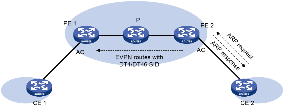
A distributed SRv6 gateway allocates an End.DT4 or End.DT46 SID to a MAC/IP advertisement route to identify the VPN instance to which the packets that match the route belong.
As shown in Figure 4, the ARP learning and BGP EVPN route advertisement process is as follows:
1. CE 2 sends an ARP request to obtain the MAC address of the gateway (a VSI interface on PE 2).
2. When PE 2 receives the ARP request from an AC, it identifies the VSI of the AC, and searches for the VSI interface associated with the VSI.
3. PE 2 relies to the ARP request with the MAC address of the VSI interface. At the same time, PE 2 learns the ARP information of CE 2 to the VPN instance bound to the VSI interface and generates a FIB entry for the ARP information.
4. PE 2 advertises the ARP information to PE 1 in a MAC/IP advertisement route. The route includes the End.DT4 or End.DT46 SID allocated by PE 2 to the VPN instance.
5. PE 1 matches the route targets in the route with the local import route targets for a matching VPN instance. If a matching VPN instance is found, PE 1 learns the ARP information to the ARP table of the matching VPN instance and generates a FIB entry for the ARP information. The FIB entry includes the End.DT4 or End.DT46 SID allocated by PE 2.
In this process, both PE 1 and PE 2 have learned the ARP information of CE 2 and CE 2 has learned the MAC address of the gateway. In the same way, PE 1 and PE 2 can learn the ARP information of CE 1 and CE 1 can learn the MAC address of the gateway.
Figure 4 Control plane working mechanisms
Data plane traffic forwarding
A distributed SRv6 gateway supports SRv6 BE mode, SRv6 TE mode, and SRv6 TE and SRv6 BE hybrid mode.
The following information uses the SRv6 BE mode as an example to illustrate the forwarding process for traffic from CE 1 to CE 2:
1. CE 1 sends a packet destined for CE 2 to gateway PE 1. The destination MAC address of the packet is the MAC address of a VSI interface on PE 1.
2. When PE 1 receives the packet from an AC, it finds that the destination MAC address of the packet is the MAC address of a local VSI interface. Then, PE 1 performs the following operations:
a. Removes the frame header of the packet.
b. Searches for a matching entry in the FIB of the VPN instance bound to the VSI interface based on the destination IP address of the packet. The matching entry contains the End.DT4 or End.DT46 SID allocated by PE 2 to the VPN instance.
3. PE 1 encapsulates an outer IPv6 header to the packet and forwards the packet to PE 2.
¡ The destination IPv6 address of the outer IPv6 header is the End.DT4 or End.DT46 SID.
¡ The source IPv6 address of the outer IPv6 header is manually configured.
4. When PE 2 receives the packet, it searches the FIB of the VPN instance identified by the End.DT4 or End.DT46 SID for the output interface. The output interface is an AC. Then, PE 2 removes the outer IPv6 header from the packet andforwards the packet out of the AC to CE 2.
Restrictions and guidelines: Distributed SRv6 gateway configuration
Make sure a VSI interface uses the same MAC address to provide service on distributed SRv6 gateways connected to IPv4 sites.
If both ARP flood suppression and local proxy ARP are enabled on a distributed SRv6 gateway, only local proxy ARP takes effect. As a best practice, do not use these features together on distributed SRv6 gateways.
Distributed SRv6 gateway tasks at a glance
To configure a distributed SRv6 gateway:
2. Configuring an EVPN instance
4. Configuring a VSI interface as a distributed SRv6 gateway
5. Configuring packet forwarding methods
¡ Configuring the route recursion mode
¡ Configuring SRv6 TE policy traffic steering
This task is required when the SRv6 TE or SRv6 TE and SRv6 BE hybrid mode is used.
7. Configuring PEs to exchange BGP EVPN routes
8. Specifying a source address for the IPv6 packets encapsulated by a distributed SRv6 gateway
9. Configuring BGP EVPN route redistribution and advertisement
10. Managing remote MAC address entries and remote ARP learning
Prerequisites for distributed SRv6 gateway configuration
For a VM that requires access to the external network at Layer 3, specify the VM's VSI interface on the border gateway as the next hop by using one of the following methods:
· Configure a static route.
· Configure a routing policy, and apply the policy by using the apply default-next-hop or apply next-hop command. For more information about configuring routing policies, see routing policy configuration in Layer 3—IP Routing Configuration Guide.
Creating a VSI
Restrictions and guidelines
For more information about the commands in this task, see VPLS commands in MPLS Command Reference.
Procedure
1. Enter system view.
system-view
2. Enable L2VPN.
l2vpn enable
By default, L2VPN is disabled.
3. Create a VSI and enter VSI view.
vsi vsi-name
4. Bring up the VSI.
undo shutdown
By default, a VSI is not administratively down.
Configuring an EVPN instance
About this task
The BGP EVPN routes advertised by a PE carry the RD and route targets configured for the EVPN instance of the routes.
Procedure
1. Enter system view.
system-view
2. Enter VSI view.
vsi vsi-name
3. Create an EVPN instance and enter EVPN instance view.
evpn encapsulation srv6
4. Specify an RD for the EVPN instance.
route-distinguisher route-distinguisher
By default, no RD is specified for an EVPN instance.
For more information about this command, see EVPN Command Reference.
5. Configure route targets for the EVPN instance.
vpn-target { vpn-target&<1-8> } [ both | export-extcommunity | import-extcommunity ]
By default, an EVPN instance does not have route targets.
For more information about this command, see EVPN Command Reference.
|
Parameter |
Description |
|
export-extcommunity |
Do not specify the same export targets for different EVPN instances. Do not specify the same export targets for the EVPN instances created in different views (VSI view, VPN instance view, public instance view, and cross-connect group view). As a best practice, the export targets configured for the following objects do not match the import targets configured for the EVPN instances created in cross-connect group view: · VPN instances. · The public instance. · EVPN instances created in VSI view, VPN instance view, and public instance view. |
|
import-extcommunity |
As a best practice, the import targets configured for the following objects do not match the export targets configured for the EVPN instances created in cross-connect group view: · VPN instances. · The public instance. · EVPN instances created in VSI view, VPN instance view, and public instance view. |
6. (Optional.) Apply a tunnel policy to the EVPN instance.
tunnel-policy tunnel-policy-name
By default, no tunnel policy is applied to an EVPN instance.
For more information about this command, see EVPN Command Reference.
Configuring SRv6 SIDs
Restrictions and guidelines
For more information about the commands in this task, see SRv6 commands in Segment Routing Command Reference.
Procedure
1. Enter system view.
system-view
2. Enable SRv6 and enter SRv6 view.
segment-routing ipv6
3. Configure a locator and enter SRv6 locator view.
locator locator-name [ ipv6-prefix ipv6-address prefix-length [ args args-length | static static-length ] * ]
4. Configure the opcode portion.
¡ Configure End.DT4 SIDs.
opcode opcode end-dt4 [ vpn-instance vpn-instance-name [ evpn ] ]
The specified VPN instance must exist. You cannot configure the same End.DT4 SID for different VPN instances.
¡ Configure End.DT46 SIDs.
opcode opcode end-dt46 [ vpn-instance vpn-instance-name [ evpn ] ]
The specified VPN instance must exist. You cannot configure the same End.DT46 SID for different VPN instances.
Configuring a VSI interface as a distributed SRv6 gateway
About this task
To save Layer 3 interface resources on a distributed SRv6 gateway, multiple EVPN VPLS networks can share one VSI interface. You can assign multiple IPv4 addresses to the VSI interface for the EVPN VPLS networks to use as gateway addresses.
When multiple EVPN VPLS networks share a VSI interface, you must specify the subnet of each VSI for the VSI interface to identify the VSI of a packet. The subnets must be unique.
Procedure
1. Enter system view.
system-view
2. Create a VSI interface and enter VSI interface view.
interface vsi-interface vsi-interface-id
For more information about this command, see VXLAN Command Reference.
3. Assign an IP address to the VSI interface.
ip address ip-address { mask | mask-length } [ sub ]
By default, no IP address is assigned to a VSI interface.
4. Assign a MAC address to the VSI interface.
mac-address mac-address
By default, no MAC address is configured for a VSI interface.
To ensure correct forwarding after VM migration, you must assign the same MAC address to the VSI interfaces of an EVPN VPLS network on all distributed SRv6 gateways.
5. Specify the VSI interface as a distributed gateway.
distributed-gateway local
By default, a VSI interface is not a distributed gateway.
For more information about this command, see VXLAN Command Reference.
6. (Optional.) Enable local proxy ARP.
local-proxy-arp enable [ ip-range startIP to endIP ]
By default, local proxy ARP is disabled.
For more information about this command, see proxy ARP commands in Layer 3—IP Services Command Reference.
7. Return to system view.
quit
8. Enter VSI view.
vsi vsi-name
9. Specify the VSI interface as the gateway interface for the VSI.
gateway vsi-interface vsi-interface-id
By default, no gateway interface is specified for a VSI.
For more information about this command, see VXLAN Command Reference.
10. Assign a subnet to the VSI.
gateway subnet ipv4-address wildcard-mask
By default, no subnet exists on a VSI.
For more information about this command, see VXLAN Command Reference.
Configuring the route recursion mode
About this task
After a PE receives a customer packet destined for an End.DT4 or End.DT46 SID, it forwards the packet according to the route recursion mode.
· SRv6 BE mode—In this mode, the PE first encapsulates the SID into the packet. Then, the PE searches the IPv6 routing table based on the SID encapsulated in the packet to forward the packet.
· SRv6 TE mode—In this mode, the PE first searches for a matching SRv6 TE policy based on the color attribute or next hop address of a matching route. Then, the PE adds an SRH to the packet. The SRH includes the End.DT4 or End.DT46 SID and the SID list of the SRv6 TE policy. Finally, the PE forwards the encapsulated packet through the SRv6 TE policy.
· SRv6 TE and SRv6 BE hybrid mode—In this mode, the PE preferentially uses the SRv6 TE mode to forward the packet. If no SRv6 TE policy is available for the packet, the PE forwards the packet in SRv6 BE mode.
Prerequsites
To use the SRv6 TE mode or the SRv6 TE and SRv6 BE hybrid mode, you must configure SRv6 TE policy traffic steering. For more information, see "Configuring SRv6 TE policy traffic steering."
Procedure
1. Enter system view.
system-view
2. Enter VSI view.
vsi vsi-name
3. Enter EVPN instance view.
evpn encapsulation srv6
4. Configure the route recursion mode.
segment-routing ipv6 { best-effort | traffic-engineer [ best-effort ] }
By default, a PE searches the IPv6 routing table based on the next hop of a matching EVPN route to forward traffic.
Configuring SRv6 TE policy traffic steering
Restrictions and guidelines for SRv6 TE policy traffic steering
This task is required if the route recursion mode is SRv6 TE mode or SRv6 TE and SRv6 BE hybrid mode.
Color-based traffic steering takes precedence over tunnel policy-based traffic steering.
Configuring color-based traffic steering
About this task
The device searches for an SRv6 TE policy that has the same color and endpoint address as the color and next hop address of a BGP EVPN route. If a matching SRv6 TE policy exists, the device recurses the route to that SRv6 TE policy. When the device receives packets that match the route, it forwards the packets through the SRv6 TE policy.
Prerequisites
To use color-based traffic steering, you need to add the color extended community to BGP EVPN routes by using routing policy or other methods. For information about the routing policy configuration, see Layer 3—IP Routing Configuration Guide.
Restrictions and guidelines
Traffic steering is based on the greatest value among the color extended community attributes when the following conditions exist:
· You specify the additive keyword for the apply extcommunity color clause in a routing policy, and specify the routing policy for the import route-policy command.
· The received BGP EVPN routes carry the color extended community attribute.
Procedure
1. Enter system view.
system-view
2. Enter routing policy node view.
route-policy route-policy-name { deny | permit } node node-number
For more information about this command, see routing policy commands in Layer 3—IP Routing Command Reference.
3. Set the color extended community attribute for BGP routes.
apply extcommunity color color [ additive ]
By default, no color extended community attribute is set for BGP routes.
For more information about this command, see routing policy commands in Layer 3—IP Routing Command Reference.
4. Return to system view.
quit
5. Enter VSI view.
vsi vsi-name
6. Enter VSI EVPN instance view.
evpn encapsulation srv6
7. Apply the routing policy as an import policy to the EVPN instance.
import route-policy route-policy
By default, no import routing policy is applied to an EVPN instance. The EVPN instance does not filter received routes.
8. Apply the routing policy as an export policy to the EVPN instance.
export route-policy route-policy
By default, no export routing policy is applied to an EVPN instance. The EVPN instance does not filter advertised routes.
Configuring tunnel policy-based traffic steering
About this task
The device searches the tunnel policies for a matching SRv6 TE policy based on the next hop of a matching route and uses the paths in the policy as public tunnels to forward private network packets. For more information about tunnel policies, see MPLS Configuration Guide.
Creating a tunnel policy
1. Enter system view.
system-view
2. Create a tunnel policy and enter tunnel policy view.
tunnel-policy tunnel-policy-name [ default ]
3. Configure the tunnel policy. Choose a minimum of one option:
¡ Bind tunnels to a destination IP address in a tunnel policy, so the tunnels can be used only for a specific VPN service.
binding-destination dest-ipv6-address { srv6-policy group srv6-policy-group-id | srv6-policy { name policy-name | end-point ipv6 ipv6-address color color-value } } [ ignore-destination-check ] [ down-switch ]
By default, a tunnel policy does not bind tunnels to a destination IP address.
¡ Specify an SRv6 TE policy as a preferred tunnel of the tunnel policy.
preferred-path srv6-policy { name srv6-policy-name | end-point ipv6 ipv6-address color color-value }
By default, no preferred tunnel is specified for a tunnel policy.
¡ Configuring SRv6 TE policy load sharing for the tunnel policy.
select-seq srv6-policy load-balance-number number
By default, no load sharing tunnel policy is configured.
For more information about the tunnel policy commands, see MPLS Command Reference.
Specifying a tunnel policy for an EVPN instance
1. Enter system view.
system-view
2. Enter VSI view.
vsi vsi-name
3. Enter VSI EVPN instance view.
evpn encapsulation srv6
4. Specify a tunnel policy for the EVPN instance.
tunnel-policy tunnel-policy-name
By default, no tunnel policy is specified for an EVPN instance.
Mapping ACs to a VSI
Mapping a Layer 3 interface to a VSI
About this task
To assign the customer traffic on a Layer 3 interface to a VSI, map that interface to the VSI. The VSI uses its MAC address table to forward the customer traffic.
For more information about the command in this task, see VPLS commands in MPLS Command Reference.
Procedure
1. Enter system view.
system-view
2. Enter Layer 3 interface view.
interface interface-type interface-number
3. Map the Layer 3 interface to a VSI.
xconnect vsi vsi-name [ access-mode { ethernet | vlan } ] [ track track-entry-number&<1-3> ]
By default, a Layer 3 interface is not mapped to a VSI.
Configuring PEs to exchange BGP EVPN routes
Restrictions and guidelines
For more information about BGP commands, see Layer 3—IP Routing Command Reference.
Procedure
1. Enter system view.
system-view
2. Enter BGP instance view.
bgp as-number [ instance instance-name ]
3. Configure an IPv6 peer or peer group.
peer { group-name | ipv6-address [ prefix-length ] } as-number as-number
4. Specify the source interface of TCP connections to a peer or peer group.
peer { group-name | ipv6-address [ prefix-length ] } connect-interface interface-type interface-number
By default, BGP uses the IPv6 address of the output interface in the optimal route to a BGP peer or peer group as the source address of TCP connections to the peer or peer group.
5. Enter BGP EVPN address family view.
address-family l2vpn evpn
6. Enable BGP to exchange EVPN routes with an IPv6 peer or peer group.
peer { group-name | ipv6-address [ prefix-length ] } enable
By default, BGP cannot exchange EVPN routes with an IPv6 peer or peer group.
7. Enable BGP to advertise SRv6-encapsulated EVPN routes to a peer or peer group.
peer { group-name | ipv6-address [ prefix-length ] } advertise encap-type srv6
By default, BGP advertises VXLAN-encapsulated EVPN routes to a peer or peer group.
Specifying a source address for the IPv6 packets encapsulated by a distributed SRv6 gateway
Restrictions and guidelines
To ensure that a distributed SRv6 gateway can forward data traffic, you must specify s source address for the outer IPv6 header encapsulated by the distributed SRv6 gateway.
You can specify any IPv6 address as the source address. As a best practice, specify an unused IPv6 address.
Procedure
1. Enter system view.
system-view
2. Enter SRv6 view.
segment-routing ipv6
3. Specify a source address for the IPv6 packets encapsulated by the distributed SRv6 gateway.
encapsulation source-address ipv6-address [ ip-ttl ttl-value ]
By default, no source address is specified for the IPv6 packets encapsulated by a distributed SRv6 gateway.
Configuring BGP EVPN route redistribution and advertisement
Redistributing MAC/IP advertisement routes into BGP unicast routing tables
About this task
This task enables the device to redistribute received MAC/IP advertisement routes that contain ARP information into a BGP unicast routing table.
· If you perform this task for the BGP IPv4 unicast address family, the device will redistribute the routes into the BGP IPv4 unicast routing table. In addition, the device will advertise the routes to the local site.
· If you perform this task for the BGP-VPN IPv4 unicast address family, the device will redistribute the routes into the BGP-VPN IPv4 unicast routing table of the corresponding VPN instance. To advertise the routes to the local site, you must configure the advertise l2vpn evpn command.
Procedure
1. Enter system view.
system-view
2. Enter BGP instance view.
bgp as-number [ instance instance-name ]
3. Enter BGP IPv4 unicast address family view or BGP-VPN IPv4 unicast address family view.
¡ Enter BGP IPv4 unicast address family view.
address-family ipv4
¡ Execute the following commands in sequence to enter BGP-VPN IPv4 unicast address family view.
ip vpn-instance vpn-instance-name
address-family ipv4
4. Redistribute MAC/IP advertisement routes that contain ARP information into the BGP-VPN IPv4 unicast routing table and allow advertisement of these routes.
import evpn mac-ip
By default, MAC/IP advertisement routes that contain ARP information can be redistributed into the BGP IPv4 unicast routing table in an SRv6 network, but advertisement of these routes is not allowed.
Enabling BGP EVPN route advertisement to the local site
About this task
This feature enables the device to advertise BGP EVPN routes to the local site after the device adds the routes to the routing table of a VPN instance.
Procedure
1. Enter system view.
system-view
2. Enter BGP instance view.
bgp as-number [ instance instance-name ]
3. Enter BGP-VPN instance view.
ip vpn-instance vpn-instance-name
4. Enter BGP-VPN IPv4 unicast address family view.
address-family ipv4 [ unicast ]
5. Enable BGP EVPN route advertisement to the local site.
advertise l2vpn evpn
By default, BGP EVPN route advertisement to the local site is enabled.
Managing remote MAC address entries and remote ARP learning
Disabling MAC address advertisement
About this task
The MAC information and ARP information advertised by the PE overlap. To avoid duplication, disable MAC address advertisement and withdraw the MAC addresses advertised to remote PEs.
Procedure
1. Enter system view.
system-view
2. Enter VSI view.
vsi vsi-name
3. Enter VSI EVPN instance view.
evpn encapsulation srv6
4. Disable MAC address advertisement and withdraw advertised MAC addresses.
mac-advertising disable
By default, MAC address advertisement is enabled.
Disabling learning of MAC addresses from ARP information
About this task
The MAC information and ARP information advertised by a remote PE overlap. To avoid duplication, disable the learning of MAC addresses from ARP information. EVPN will learn remote MAC addresses only from the MAC information advertised from remote sites.
Procedure
1. Enter system view.
system-view
2. Enter VSI view.
vsi vsi-name
3. Enter VSI EVPN instance view.
evpn encapsulation srv6
4. Disable the EVPN instance from learning MAC addresses from ARP information.
arp mac-learning disable
By default, an EVPN instance learns MAC addresses from ARP information.
Verifying and maintaining distributed SRv6 gateways
Perform display tasks in any view.
· Display EVPN ARP information.
display evpn route arp [ local | remote ] [ public-instance | vpn-instance vpn-instance-name ] [ count ]
· Display EVPN routing table information.
display evpn routing-table [ ipv6 ] { public-instance | vpn-instance vpn-instance-name } [ count ]
· Display IPv4 routing table information.
display ip routing-table [ all-vpn-instance | vpn-instance vpn-instance-name ] [ verbose ]
Distributed SRv6 gateway configuration examples
Example: Configuring distributed SRv6 gateways
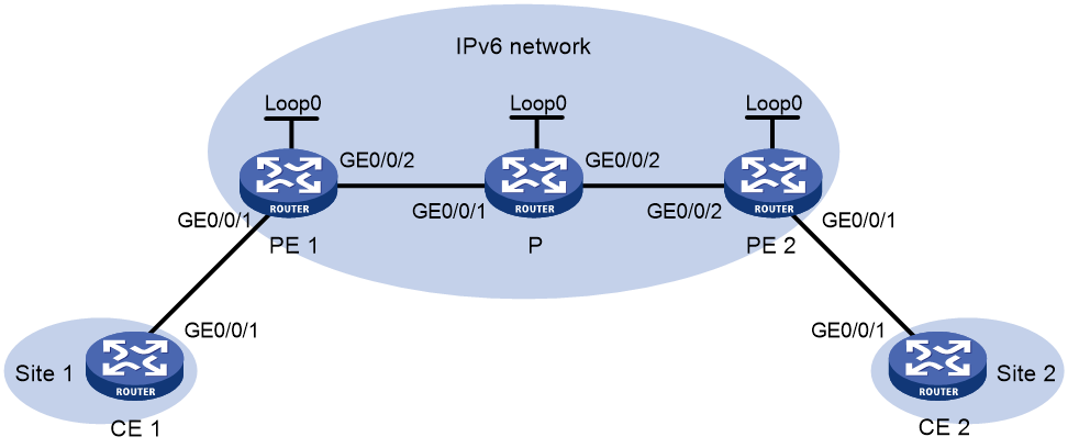
Network configuration
As shown in Figure 5, PE 1 and PE 2 are distributed SRv6 gateways in the EVPN VPLS over SRv6 network. They forward Layer 3 traffic in different subnets across sistes.
|
Device |
Interface |
IP address |
Device |
Interface |
IP address |
|
PE 1 |
Loop0 |
1::1/128 |
PE 2 |
Loop0 |
2::2/128 |
|
|
VSI-int1 |
100.1.1.1/24 |
|
GE0/0/1 |
- |
|
|
GE0/0/1 |
- |
|
GE0/0/2 |
30::2/64 |
|
|
GE0/0/2 |
20::1/64 |
|
VSI-int1 |
100.1.2.1/24 |
|
P |
Loop0 |
3::3/128 |
CE 1 |
GE0/0/1 |
100.1.1.10/24 |
|
|
GE0/0/1 |
20::2/64 |
CE 2 |
GE0/0/1 |
100.1.2.20/24 |
|
|
GE0/0/2 |
30::1/64 |
|
|
|
Procedure
1. Configure IP address and unicast routing settings:
# On CE 1, configure a default route and specify gateway address 100.1.1.1 for the route.
<CE1> system-view
[CE1] ip route-static 0.0.0.0 0 100.1.1.1
# On CE2, configure a default route and specify gateway address 10.1.2.1 for the route.
<CE2> system-view
[CE2] ip route-static 0.0.0.0 0 100.1.2.1
# Configure IP addresses and masks for the interfaces, as shown in Figure 5. (Details not shown.)
# In the IPv6 network, configure OSPFv3 to ensure that the devices can reach each other. (Details not shown.)
2. Configure PE 1:
# Enable L2VPN.
<PE1> system-view
[PE1] l2vpn enable
# Configure RD and route target settings for VPN instance vpn1.
[PE1] ip vpn-instance vpn1
[PE1-vpn-instance-vpn1] route-distinguisher 1:1
[PE1-vpn-instance-vpn1] address-family ipv4
[PE1-vpn-ipv4-vpn1] vpn-target 1:1 import-extcommunity
[PE1-vpn-ipv4-vpn1] vpn-target 1:1 export-extcommunity
[PE1-vpn-ipv4-vpn1] quit
[PE1-vpn-instance-vpn1] address-family evpn
[PE1-vpn-evpn-vpn1] vpn-target 2:2 import-extcommunity
[PE1-vpn-evpn-vpn1] vpn-target 2:2 export-extcommunity
[PE1-vpn-evpn-vpn1] quit
[PE1-vpn-instance-vpn1] quit
# Configure VSI-interface 1.
[PE1] interface vsi-interface 1
[PE1-Vsi-interface1] ip binding vpn-instance vpn1
[PE1-Vsi-interface1] ip address 100.1.1.1 255.255.255.0
[PE1-Vsi-interface1] mac-address 0001-0001-0001
[PE1-Vsi-interface1] local-proxy-arp enable
[PE1-Vsi-interface1] distributed-gateway local
[PE1-Vsi-interface1] quit
# Configure VSI vpna.
[PE1] vsi vpna
[PE1-vsi-vpna] gateway vsi-interface 1
[PE1-vsi-vpna] evpn encapsulation srv6
[PE1-vsi-vpna-evpn-srv6] route-distinguisher 6:6
[PE1-vsi-vpna-evpn-srv6] vpn-target 6:6 import-extcommunity
[PE1-vsi-vpna-evpn-srv6] vpn-target 6:6 export-extcommunity
[PE1-vsi-vpna-evpn-srv6] segment-routing ipv6 locator aaa
[PE1-vsi-vpna-evpn-srv6] segment-routing ipv6 best-effort
[PE1-vsi-vpna-evpn-srv6] quit
[PE1-vsi-vpna] quit
# Configure a locator for SRv6 SID allocation.
[PE1] segment-routing ipv6
[PE1-segment-routing-ipv6] encapsulation source-address 1::1
[PE1-segment-routing-ipv6] locator aaa ipv6-prefix 1:1:: 64 static 32
[PE1-segment-routing-ipv6-locator-aaa] quit
# Configure BGP peers.
[PE1] bgp 100
[PE1-bgp-default] router-id 1.1.1.1
[PE1-bgp-default] peer 2::2 as-number 100
[PE1-bgp-default] peer 2::2 connect-interface loopback 0
# Configure the BGP EVPN address family.
[PE1-bgp-default] address-family l2vpn evpn
[PE1-bgp-default-evpn] peer 2::2 enable
[PE1-bgp-default-evpn] peer 2::2 advertise encap-type srv6
[PE1-bgp-default-evpn] quit
# Configure the BGP IPv4 VPN instance.
[PE1-bgp-default] ip vpn-instance vpn1
[PE1-bgp-default-vpn1] address-family ipv4 unicast
[PE1-bgp-default-ipv4-vpn1] import evpn mac-ip
[PE1-bgp-default-ipv4-vpn1] advertise l2vpn evpn
[PE1-bgp-default-ipv4-vpn1] segment-routing ipv6 best-effort evpn
[PE1-bgp-default-ipv4-vpn1] segment-routing ipv6 locator aaa evpn
[PE1-bgp-default-ipv4-vpn1] quit
# Map GigabitEthernet 0/0/1 (the interface connected to CE 1) with VSI vpna.
[PE1] interface gigabitethernet 0/0/1
[PE1-GigabitEthernet0/0/1] xconnect vsi vpna
[PE1-GigabitEthernet0/0/1] quit
3. Configure PE 2:
# Enable L2VPN.
<PE2> system-view
[PE2] l2vpn enable
# Configure RD and route target settings for VPN instance vpn1.
[PE2] ip vpn-instance vpn1
[PE2-vpn-instance-vpn1] route-distinguisher 1:1
[PE2-vpn-instance-vpn1] address-family ipv4
[PE2-vpn-ipv4-vpn1] vpn-target 1:1 import-extcommunity
[PE2-vpn-ipv4-vpn1] vpn-target 1:1 export-extcommunity
[PE2-vpn-ipv4-vpn1] quit
[PE2-vpn-instance-vpn1] address-family evpn
[PE2-vpn-evpn-vpn1] vpn-target 2:2 import-extcommunity
[PE2-vpn-evpn-vpn1] vpn-target 2:2 export-extcommunity
[PE2-vpn-evpn-vpn1] quit
[PE2-vpn-instance-vpn1] quit
# Configure VSI-interface 1.
[PE2] interface vsi-interface 1
[PE2-Vsi-interface1] ip binding vpn-instance vpn1
[PE2-Vsi-interface1] ip address 100.1.1.1 255.255.255.0
[PE2-Vsi-interface1] mac-address 0001-0001-0001
[PE2-Vsi-interface1] local-proxy-arp enable
[PE2-Vsi-interface1] distributed-gateway local
[PE2-Vsi-interface1] quit
# Configure VSI vpna.
[PE2] vsi vpna
[PE2-vsi-vpna] gateway vsi-interface 1
[PE2-vsi-vpna] evpn encapsulation srv6
[PE2-vsi-vpna-evpn-srv6] route-distinguisher 6:6
[PE2-vsi-vpna-evpn-srv6] vpn-target 6:6 import-extcommunity
[PE2-vsi-vpna-evpn-srv6] vpn-target 6:6 export-extcommunity
[PE2-vsi-vpna-evpn-srv6] segment-routing ipv6 locator aaa
[PE2-vsi-vpna-evpn-srv6] segment-routing ipv6 best-effort
[PE2-vsi-vpna-evpn-srv6] quit
[PE2-vsi-vpna] quit
# Configure a locator for SRv6 SID allocation.
[PE2] segment-routing ipv6
[PE2-segment-routing-ipv6] encapsulation source-address 2::2
[PE2-segment-routing-ipv6] locator aaa ipv6-prefix 2:2:: 64 static 32
[PE2-segment-routing-ipv6-locator-aaa] quit
# Configure BGP peers.
[PE2] bgp 100
[PE2-bgp-default] router-id 2.2.2.2
[PE2-bgp-default] peer 1::1 as-number 100
[PE2-bgp-default] peer 1::1 connect-interface loopback 0
# Configure the BGP EVPN address family.
[PE2-bgp-default] address-family l2vpn evpn
[PE2-bgp-default-evpn] peer 1::1 enable
[PE2-bgp-default-evpn] peer 1::1 advertise encap-type srv6
[PE2-bgp-default-evpn] quit
# Configure the BGP IPv4 VPN instance.
[PE2-bgp-default] ip vpn-instance vpn1
[PE2-bgp-default-vpn1] address-family ipv4 unicast
[PE2-bgp-default-ipv4-vpn1] import evpn mac-ip
[PE2-bgp-default-ipv4-vpn1] segment-routing ipv6 best-effort evpn
[PE2-bgp-default-ipv4-vpn1] segment-routing ipv6 locator aaa evpn
[PE2-bgp-default-ipv4-vpn1] quit
# Map GigabitEthernet 0/0/1 (the interface connected to CE 2) with VSI vpna.
[PE2] interface gigabitethernet 0/0/1
[PE2-GigabitEthernet0/0/1] xconnect vsi vpna
[PE2-GigabitEthernet0/0/1] quit
Verifying the configuration
# On PE 1, display routing table information for VPN instance vpn1 and verify that PE 1 has learned the host route of CE 2.
[PE1] display ip routing-table vpn-instance vpn1
Destinations : 11 Routes : 11
Destination/Mask Proto Pre Cost NextHop Interface
0.0.0.0/32 Direct 0 0 127.0.0.1 InLoop0
100.1.1.0/24 Direct 0 0 100.1.1.1 Vsi1
100.1.1.0/32 Direct 0 0 100.1.1.1 Vsi1
100.1.1.1/32 Direct 0 0 127.0.0.1 InLoop0
100.1.1.255/32 Direct 0 0 100.1.1.1 Vsi1
100.1.2.20/32 BGP 255 0 2:2:: GE0/0/2
127.0.0.0/8 Direct 0 0 127.0.0.1 InLoop0
127.0.0.0/32 Direct 0 0 127.0.0.1 InLoop0
127.0.0.1/32 Direct 0 0 127.0.0.1 InLoop0
127.255.255.255/32 Direct 0 0 127.0.0.1 InLoop0
255.255.255.255/32 Direct 0 0 127.0.0.1 InLoop0
# On PE 2, display routing table information for VPN instance vpn1 and verify that PE 2 has learned the host route of CE 1.
[PE2] display ip routing-table vpn-instance vpn1
Destinations : 11 Routes : 11
Destination/Mask Proto Pre Cost NextHop Interface
0.0.0.0/32 Direct 0 0 127.0.0.1 InLoop0
100.1.2.0/24 Direct 0 0 100.1.1.1 Vsi1
100.1.2.0/32 Direct 0 0 100.1.1.1 Vsi1
100.1.2.1/32 Direct 0 0 127.0.0.1 InLoop0
100.1.1.10/32 BGP 255 0 1:1:: GE0/0/2
100.1.2.255/32 Direct 0 0 100.1.1.1 Vsi1
127.0.0.0/8 Direct 0 0 127.0.0.1 InLoop0
127.0.0.0/32 Direct 0 0 127.0.0.1 InLoop0
127.0.0.1/32 Direct 0 0 127.0.0.1 InLoop0
127.255.255.255/32 Direct 0 0 127.0.0.1 InLoop0
255.255.255.255/32 Direct 0 0 127.0.0.1 InLoop0
# Verify that CE 1 and CE 2 can ping each other. (Details not shown.)