- Table of Contents
-
- 07-Layer 3—IP Services Configuration Guide
- 00-Preface
- 01-ARP configuration
- 02-IP addressing configuration
- 03-DHCP configuration
- 04-DNS configuration
- 05-HTTP configuration
- 06-IP forwarding basics configuration
- 07-Fast forwarding configuration
- 08-Adjacency table configuration
- 09-IRDP configuration
- 10-IP performance optimization configuration
- 11-UDP helper configuration
- 12-IPv6 basics configuration
- 13-IPv6 neighbor discovery configuration
- 14-DHCPv6 configuration
- 15-IPv6 fast forwarding configuration
- 16-IPv6 transition technologies configuration
- 17-WAAS configuration
- 18-HTTP redirect configuration
- 19-Web caching configuration
- Related Documents
-
| Title | Size | Download |
|---|---|---|
| 06-IP forwarding basics configuration | 60.58 KB |
Contents
Configuring IP forwarding basic settings························································ 1
About FIB table······························································································································· 1
Enabling last hop holding················································································································ 1
Displaying and maintaining FIB table································································································ 2
Configuring IP forwarding basic settings
About FIB table
A device uses the FIB table to make packet forwarding decisions.
A device selects optimal routes from the routing table, and puts them into the FIB table. Each FIB entry specifies the next hop IP address and output interface for packets destined for a specific subnet or host.
For more information about the routing table, see Layer 3—IP Routing Configuration Guide.
Use the display fib command to display the FIB table. The following example displays the entire FIB table.
<Sysname> display fib
Destination count: 4 FIB entry count: 4
Flag:
U:Usable G:Gateway H:Host B:Blackhole D:Dynamic S:Static
R:Relay F:FRR
Destination/Mask Nexthop Flag OutInterface/Token Label
10.2.0.0/16 10.2.1.1 U GE1/0/1 Null
10.2.1.1/32 127.0.0.1 UH InLoop0 Null
127.0.0.0/8 127.0.0.1 U InLoop0 Null
127.0.0.1/32 127.0.0.1 UH InLoop0 Null
A FIB entry includes the following items:
· Destination—Destination IP address.
· Mask—Network mask. The mask and the destination address identify the destination network. A logical AND operation between the destination address and the network mask yields the address of the destination network. For example, if the destination address is 192.168.1.40 and the mask 255.255.255.0, the address of the destination network is 192.168.1.0. A network mask includes a certain number of consecutive 1s. It can be expressed in dotted decimal format or by the number of the 1s.
· Nexthop—IP address of the next hop.
· Flag—Route flag.
· OutInterface—Output interface.
· Token—MPLS Label Switched Path index number.
· Label—Inner label.
Enabling last hop holding
About this task
Last hop holding implements symmetric routing.
When the interface enabled with this feature receives the first IP packet of a forward flow, this feature implements the following operations:
· Obtains the forward flow information and last hop information of the packet.
· Based on the obtained information, creates a fast forwarding entry for the return flow.
When packets of the return flow arrive at the device, the device forwards those packets according to the entry.
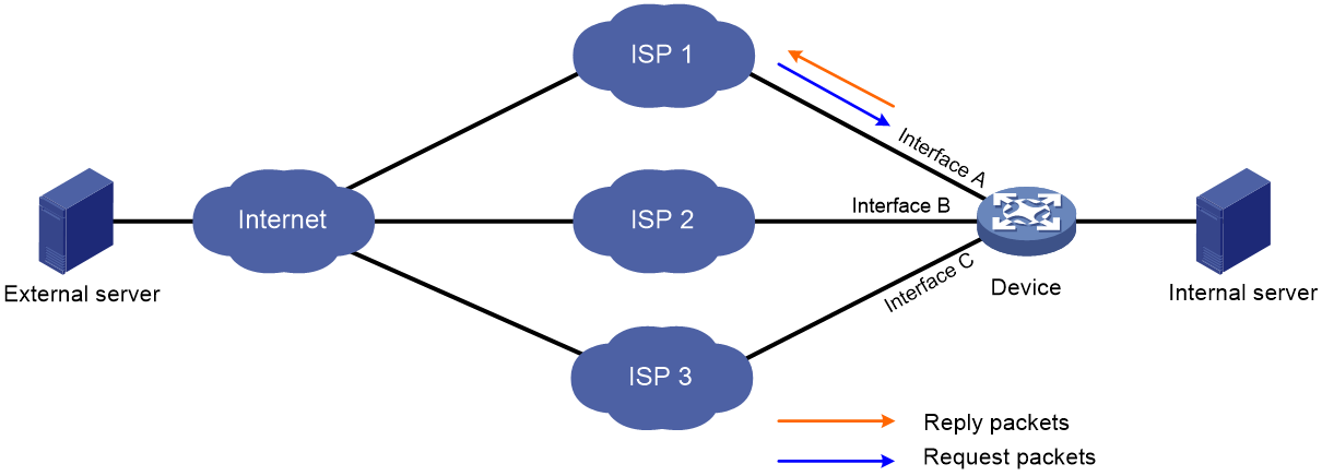
As is shown in Figure 1, when the external server sends a request to the internal server, the packet travels through ISP 1 to Interface A on the device. The last hop holding feature on the device ensures that the reply packet follows the same route as the request packet back to ISP 1. If last hop holding is disabled, the reply packet might be sent out of Interface B or Interface C to the external network.
Figure 1 Last hop holding application
Restrictions and guidelines
This feature relies on fast forwarding entries. If the MAC address of a last hop changes on an Ethernet link, this feature can function correctly only after the fast forwarding entry is updated for the MAC address.
This feature is not applicable to an MPLS network.
Procedure
1. Enter system view.
system-view
2. Enter interface view. Choose one of the following options:
¡ Enter Layer 3 Ethernet interface view or subinterface view.
interface interface-type { interface-number | interface-number.subnumber }
¡ Enter Dialer interface view.
interface dialer number
3. Enable last hop holding.
ip last-hop hold
By default, last hop holding is disabled.
Displaying and maintaining FIB table
To display FIB entries, execute the following command in any view:
display fib [ vpn-instance vpn-instance-name ] [ ip-address [ mask | mask-length ] ]