- Table of Contents
- Related Documents
-
| Title | Size | Download |
|---|---|---|
| 04-AC Hierarchy (IPv6) Configuration Examples | 441.91 KB |
|
|
|
H3C Access Controllers |
|
AC Hierarchy (IPv6) |
|
Configuration Examples |
Copyright © 2024 New H3C Technologies Co., Ltd. All rights reserved.
No part of this manual may be reproduced or transmitted in any form or by any means without prior written consent of New H3C Technologies Co., Ltd.
Except for the trademarks of New H3C Technologies Co., Ltd., any trademarks that may be mentioned in this document are the property of their respective owners.
The information in this document is subject to change without notice.
Introduction
The following information provides an AC hierarchy configuration example.
Prerequisites
|
|
NOTE: Support for this configuration example varies by device model and version. |
This document applies to Comware-based access controllers and access points. Procedures and information in the examples might be slightly different depending on the software or hardware version of the access controllers and access points.
The configuration examples were created and verified in a lab environment, and all the devices were started with the factory default configuration. When you are working on a live network, make sure you understand the potential impact of every command on your network.
The following information is provided based on the assumption that you have basic knowledge of IPv6, AC hierarchy, portal, WLAN access, and AP management.
Example: Configuring AC hierarchy
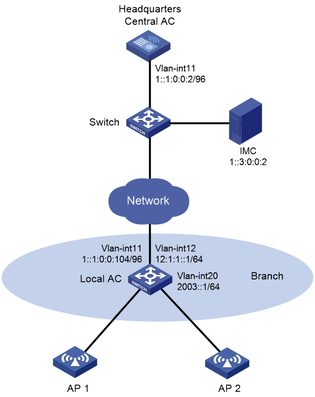
Network configuration
As shown in Figure 1, the central AC is deployed at the headquarters and a local AC (a unified wired and wireless AC) is deployed at the branch. The central AC performs client authentication and the local AC forwards client traffic.
Configure network settings to meet the following requirements:
· APs obtain the IPv6 address of the central AC through DHCPv6 and establish CAPWAP tunnels with the local AC after AC rediscovery.
· The IMC server performs portal authentication as a portal server and AAA server.
· The local AC assigns IPv6 addresses to APs and clients as a DHCPv6 server.
Analysis
· For interface GigabitEthernet1/0/1 on an AP to join the local-forwarding VLAN, use a text editor to create an AP configuration file and upload the file to the central AC.
· With AC rediscovery enabled, the APs might fail to come online through the local AC in the branch if the local AC is not the lowest-loaded AC. For the central AC to assign the local AC to the APs at AC rediscovery, specify the local AC for APs.
Restrictions and guidelines
When you configure AC hierarchy, follow these restrictions and guidelines:
· Use the actual serial ID of an AP to uniquely identify that AP.
· Do not configure any portal settings on the local AC when portal authentication and local forwarding are used in the AC hierarchy network.
· Do not enable auto AP on the local AC, and do not create APs on the local AC if the APs are to be managed centrally by the central AC.
· Disable firmware upgrade for the local AC because the S5560 unified wired and wireless AC and the access controller module have different software versions.
· The URL of the portal Web server redirected to clients does not contain any parameters by default. You must configure the parameters manually.
· Central ACs do not support IRF.
Procedures
Configuring the central AC
1. Make sure the devices can reach each other. (Details not shown.)
2. Create AP configuration file map.txt as follows and then upload the file to the central AC.
system-view
vlan 20
interface GigabitEthernet1/0/1
port link-type trunk
port trunk permit vlan 20
3. Create VLAN 11 and VLAN-interface 11, and assign an IPv6 address to the VLAN interface.
<Central AC> system-view
[Central AC] vlan 11
[Central AC-vlan11] quit
[Central AC] interface vlan-interface 11
[Central AC-Vlan-interface11] ipv6 address 1::1:0:0:2/96
[Central AC-Vlan-interface11] quit
4. Configure GigabitEthernet 1/0/1 that connects the central AC to the switch as a trunk port, and assign the port to VLAN 11.
[Central AC] interface gigabitethernet 1/0/1
[Central AC-GigabitEthernet1/0/1] port link-type trunk
[Central AC-GigabitEthernet1/0/1] port trunk permit vlan 11
[Central AC-GigabitEthernet1/0/1] quit
5. Create local AC wx3540h, and specify the serial ID of the local AC.
[Central AC] wlan local-ac name wx3540h model WX3540H
[Central AC-wlan-local-ac-wx3540h] serial-id 210235A1JQB161000013
[Central AC-wlan-local-ac-wx3540h] quit
6. Configure the RADIUS scheme for portal authentication:
# Create RADIUS scheme imc.
[Central AC] radius scheme imc
# Specify the IPv6 address of the primary authentication server as 1::3:0:0:2.
[Central AC-radius-imc] primary ipv6 authentication 1::3:0:0:2
# Specify the IPv6 address of the primary accounting server as 1::3:0:0:2.
[Central AC-radius-imc] primary ipv6 accounting 1::3:0:0:2
# Set the shared key to 12345678 in plaintext form for secure authentication communication.
[Central AC-radius-imc] key authentication simple 12345678
# Set the shared key to 12345678 in plaintext form for secure accounting communication.
[Central AC-radius-imc] key accounting simple 12345678
# Configure the central AC to remove the domain name from the usernames sent to the RADIUS servers.
[Central AC-radius-imc] user-name-format without-domain
# Specify IPv6 address 1::1:0:0:2 as the source IPv6 address of outgoing RADIUS packets.
[Central AC-radius-imc] nas-ip ipv6 1::1:0:0:2
[Central AC-radius-imc] quit
7. Configure the authentication domain for portal authentication:
# Create domain imc and enter its view.
[Central AC] domain imc
# Perform RADIUS authentication for portal users based on scheme imc.
[Central AC-isp-imc] authentication portal radius-scheme imc
# Perform RADIUS authorization for portal users based on scheme imc.
[Central AC-isp-imc] authorization portal radius-scheme imc
# Perform RADIUS accounting for portal users based on scheme imc.
[Central AC-isp-imc] accounting portal radius-scheme imc
[Central AC-isp-imc] quit
8. Configure the portal authentication server:
# Create portal authentication server imc and enter its view.
[Central AC] portal server imc
# Configure the IPv6 address of the portal authentication server as 1::3:0:0:2 and the plaintext key as 12345678.
[Central AC-portal-server-imc] ipv6 1::3:0:0:2 key simple 12345678
9. Configure the portal Web server:
# Create portal Web server imc and enter its view.
[Central AC-portal-server-imc] portal web-server imc
# Configure the URL for the portal Web server as http://[1::3:0:0:2]:8080/portal.
[Central AC-portal-server-imc] url http://[1::3:0:0:2]:8080/portal
# Configure the parameters carried in the URL of the portal Web server.
[Central AC-portal-server-imc] url-parameter apmac ap-mac
[Central AC-portal-server-imc] url-parameter ssid ssid
[Central AC-portal-server-imc] url-parameter userip source-address
[Central AC-portal-server-imc] url-parameter usermac source-mac
[Central AC-portal-server-imc] quit
10. Configure wireless services:
# Create service template portal.
[Central AC] wlan service-template portal
# Set the SSID for the service template to portal.
[Central AC-wlan-st-portal] ssid portal
# Assign clients coming online through the service template to VLAN 20.
[Central AC-wlan-st-portal] vlan 20
# Configure the central AC to perform client authentication.
[Central AC-wlan-st-portal]client-security authentication-location central-ac
# Enable APs to forward client traffic.
[Central AC-wlan-st-portal] client forwarding-location ap
# Set the AKM mode to PSK, and set the plaintext preshared key to 12345678.
[Central AC-wlan-st-portal] akm mode psk
[Central AC-wlan-st-portal] preshared-key pass-phrase simple 12345678
# Configure the CCMP cipher suite and RSN security IE.
[Central AC-wlan-st-portal] cipher-suite ccmp
[Central AC-wlan-st-portal] security-ie rsn
# Enable direct IPv6 portal authentication on the service template.
[Central AC-wlan-st-portal] portal ipv6 enable method direct
# Specify the authentication domain as imc for IPv6 portal users on the service template.
[Central AC-wlan-st-portal] portal ipv6 domain imc
# Configure the BAS-IPv6 attribute as 1::1:0:0:2 for portal packets sent to the portal authentication server.
[Central AC-wlan-st-portal] portal bas-ipv6 1::1:0:0:2
# Enable snooping ND packets and snooping DHCPv6 packets.
[Central AC-wlan-st-portal] client ipv6-snooping nd-learning enable
[Central AC-wlan-st-portal] client ipv6-snooping dhcpv6-learning enable
# Apply IPv6 portal Web server imc on the service template for portal authentication.
[Central AC-wlan-st-portal] portal ipv6 apply web-server imc
# Enable the service template.
[Central AC-wlan-st-portal] service-template enable
[Central AC-wlan-st-portal] quit
# Create AP ap1 and set the serial ID to 219801A28N819CE0002T.
[Central AC] wlan ap ap1 model WA6320
[Central AC-wlan-ap-ap1] serial-id 219801A28N819CE0002T
[Central AC-wlan-ap-ap1] quit
# Create AP group group1 and configure a grouping rule by AP name to add ap1 to the group.
[Central AC] wlan ap-group group1
[Central AC-wlan-ap-group-group1] ap ap1
|
|
NOTE: In a large-scale network, configure AP settings in AP group view instead of AP view as a best practice. |
# Enable AC rediscovery.
[Central AC-wlan-ap-group-group1] control-address enable
# Specify the local AC with IPv6 address 1::1:0:0:104 for the AP.
[Central AC-wlan-ap-group-group1] control-address ipv6 1::1:0:0:104
# Bind service template portal to radio 1.
[Central AC-wlan-ap-group-group1] ap-model WA6320
[Central AC-wlan-ap-group-group1-ap-model-WA6320] radio 1
[Central AC-wlan-ap-group-group1-ap-model-WA6320-radio-1] service-template portal
# Enable radio 1.
[Central AC-wlan-ap-group-group1-ap-model-WA6320-radio-1] radio enable
[Central AC-wlan-ap-group-group1-ap-model-WA6320-radio-1] quit
# Bind service template portal to radio 2.
[Central AC-wlan-ap-group-group1-ap-model-WA6320] radio 2
[Central AC-wlan-ap-group-group1-ap-model-WA6320-radio-2] service-template portal
# Enable radio 2.
[Central AC-wlan-ap-group-group1-ap-model-WA6320-radio-2] radio enable
[Central AC-wlan-ap-group-group1-ap-model-WA6320-radio-2] quit
# Deploy the configuration file to WA6320 APs in the AP group.
[Central AC-wlan-ap-group-group1-ap-model-WA6320] map-configuration cfa0:/map.txt
Configuring the local AC
1. Configure the local AC feature:
# Enable the local AC feature.
<Local AC> system-view
[Local AC] wlan local-ac enable
# Specify the central AC with IPv6 address 1::1:0:0:2 for the local AC.
[Local AC] wlan central-ac ipv6 1::1:0:0:2
# Configure the local AC to use VLAN 11 to establish a tunnel with the central AC.
[Local AC] wlan local-ac capwap source-vlan 11
2. Configure DHCP:
# Enable DHCP.
[Local AC] dhcp enable
# Create DHCPv6 address pool ap and specify the subnet for dynamic allocation as 12:1:1::/64.
[Local AC] ipv6 dhcp pool ap
[Local AC-dhcp-pool-ap] network 12:1:1::/64
# Configure Option 52 that specifies the AC's IPv6 address.
[Local AC-dhcp-pool-ap] option 52 hex 00010000000000000001000000000001
[Local AC-dhcp-pool-ap] quit
# Create DHCPv6 address pool client and specify the subnet for dynamic allocation as 2003::/64.
[Local AC] ipv6 dhcp pool client
[Local AC-dhcp-pool-ap] network 2003::/64
[Local AC-dhcp-pool-ap] quit
3. Configure VLAN interfaces:
# Create VLAN 11 and VLAN-interface 11, and assign an IPv6 address to the interface. The local AC uses this interface to associate with the central AC.
[Local AC] vlan 11
[Local AC-vlan11] quit
[Local AC] interface Vlan-interface11
[Local AC-Vlan-interface11] ipv6 address 1::1:0:0:104/96
[Local AC-Vlan-interface11] quit
# Create VLAN 12 and VLAN-interface 12, and assign an IPv6 address to the interface. The local AC uses this interface to associate with APs.
[Local AC] vlan 12
[Local AC-vlan12] quit
[Local AC] interface Vlan-interface12
[Local AC-Vlan-interface12] ipv6 address 12:1:1::1/64
# Disable RA message suppression, and set both the M flag and O flag to 1 in in RA advertisements to be sent.
[Local AC-Vlan-interface12] undo ipv6 nd ra halt
[Local AC-Vlan-interface12] ipv6 nd autoconfig managed-address-flag
[Local AC-Vlan-interface12] ipv6 nd autoconfig other-flag
# Enable the DHCPv6 server, and apply address pool ap to the VLAN-interface 12.
[Local AC-Vlan-interface12] ipv6 dhcp select server
[Local AC-Vlan-interface12] ipv6 dhcp server apply pool ap
[Local AC-Vlan-interface12] quit
# Create VLAN 20 and VLAN-interface 20, and assign an IPv6 address to the interface. The local AC uses this interface to provide access to clients.
[Local AC] vlan 20
[Local AC-vlan20] quit
[Local AC] interface Vlan-interface20
[Local AC-Vlan-interface20] ipv6 address 2003::1/64
# Disable RA message suppression, and set both the M flag and O flag to 1 in in RA advertisements to be sent.
[Local AC-Vlan-interface20] undo ipv6 nd ra halt
[Local AC-Vlan-interface20] ipv6 nd autoconfig managed-address-flag
[Local AC-Vlan-interface20] ipv6 nd autoconfig other-flag
# Enable the DHCPv6 server, and apply address pool client to the VLAN-interface 20.
[Local AC-Vlan-interface20] ipv6 dhcp select server
[Local AC-Vlan-interface20] ipv6 dhcp server apply pool client
[Local AC-Vlan-interface20] quit
# Configure GigabitEthernet 1/0/1 that connects the local AC to AP 1 as a trunk port, assign the port to VLAN 12 and VLAN 20, and set the PVID to 12.
[Local AC] interface GigabitEthernet 1/0/1
[Local AC-GigabitEthernet1/0/1] port link-type trunk
[Local AC-GigabitEthernet1/0/1] port trunk permit vlan 12 20
[Local AC-GigabitEthernet1/0/1] port trunk pvid vlan 12
[Local AC-GigabitEthernet1/0/1] quit
# Configure GigabitEthernet 1/0/2 that connects the local AC to AP 2 as a trunk port, assign the port to VLAN 12 and VLAN 20, and set the PVID to 12.
[Local AC] interface GigabitEthernet 1/0/2
[Local AC-GigabitEthernet1/0/2] port link-type trunk
[Local AC-GigabitEthernet1/0/2] port trunk permit vlan 12 20
[Local AC-GigabitEthernet1/0/2] port trunk pvid vlan 12
[Local AC-GigabitEthernet1/0/2] quit
# Configure GigabitEthernet 1/0/3 that connects the local AC to the headquarters as an access port, and assign the port to VLAN 11.
[Local AC] interface GigabitEthernet 1/0/3
[Local AC-GigabitEthernet1/0/3] port link-type access
[Local AC-GigabitEthernet1/0/3] port access vlan 11
[Local AC-GigabitEthernet1/0/3] quit
# Create a static route.
[Local AC] ipv6 route-static 0:0::0:0 0 1::1:0:0:2
Configuring the IMC server
This example uses the IMC server to describe the RADIUS server and portal server configuration. The IMC server runs on IMC PLAT 7.2 (E0403p10), IMC EIA 7.2 (E0405), and IMC EIP 7.2 (E0405).
To configure the IMC server:
1. Log in to IMC and click the User tab.
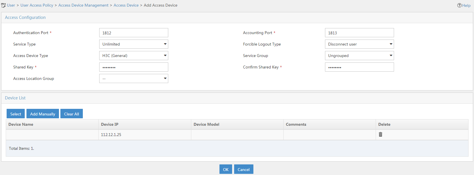
2. Add an access device.
a. In the left navigation pane, select User Access Policy > Access Device Management > Access Device.
b. Click Add.
The Add Access Device page opens.
c. In the Device List area, click Add Manually, and specify the start IP address as 1::1:0:0:2/96.
d. In the Access Configuration area, configure the following parameters:
- Enter radius in the Shared Key and Confirm Shared Key fields.
The key is consistent with the shared key configured on the AC.
- Use the default values for other parameters.
e. Click OK.
Figure 2 Adding an access device
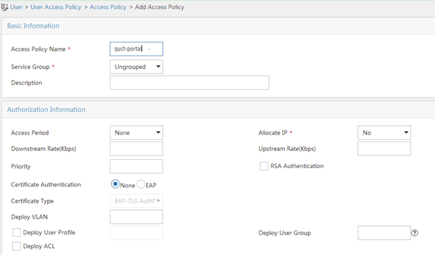
3. Add an access policy:
a. From the navigation pane, select User Access Policy > Access Policy.
b. Click Add.
c. On the Add Access Policy page, configure the following parameters:
- Enter the policy name.
- Select the service group.
- Use the default values for other parameters.
Figure 3 Adding an access policy
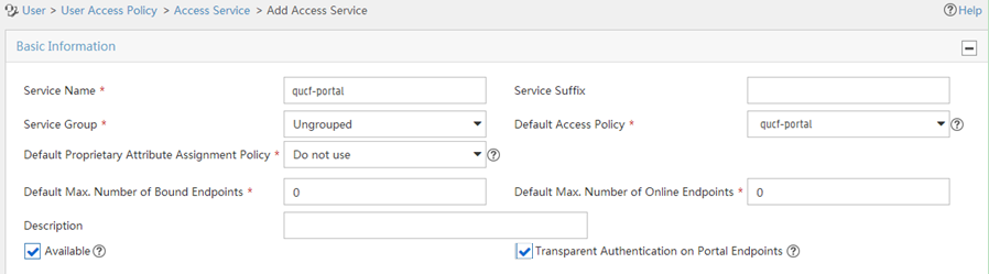
4. Add an access service:
a. From the navigation pane, select User Access Policy > Access Service.
b. Click Add.
c. On the Add Access Service page, configure the following parameters:
- Enter the service name.
- Use the default values for other parameters.
d. Click OK.
Figure 4 Adding an access service
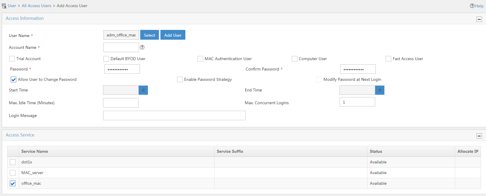
5. Add an access user:
a. From the navigation pane, select Access User > Access User.
b. Click Add.
c. In the Access Information area, add a user:
- Select a user.
- Set the password.
d. Click OK.
Figure 5 Adding an access user
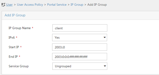
6. Create an IP group:
a. From the navigation tree, select User Access Policy > Portal Service > IP Group.
b. Click Add.
c. Configure the following parameters:
- IP Group Name—Enter the IP group name.
- Start IP—Enter the start IP address of the IP group. Make sure the client IP address is in the IP group.
- End IP—Enter the end IP address of the IP group. Make sure the client IP address is in the IP group.
- Service Group—Select a service group. This example uses the default value Ungrouped.
d. Click OK.
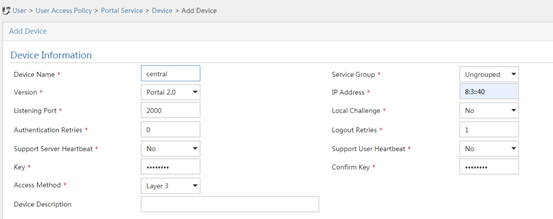
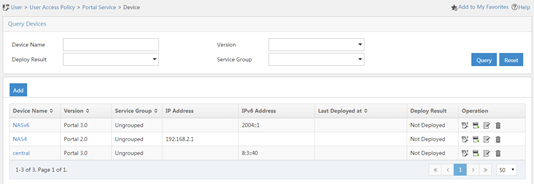
7. Add a portal device:
a. From the navigation tree, select User Access Policy > Portal Service > Device.
b. Click Add.
c. Configure the following parameters:
- Device Name—Enter the device name.
- IP Address—Enter the IP address of the AC's interface connected to the client.
- Support Server Heartbeat—Select whether to support the portal server heartbeat function. In this example, select No.
- Support User Heartbeat—Select whether to support the portal user heartbeat function. In this example, select No.
- Key—Enter the key. The key must be the same as that configured on the AC.
- Version—Select Portal 3.0. Only portal 3.0 supports IPv6.
- Access Method—Select layer 3.
Use the default settings for other parameters.
d. Click OK.
Figure 7 Adding a portal device
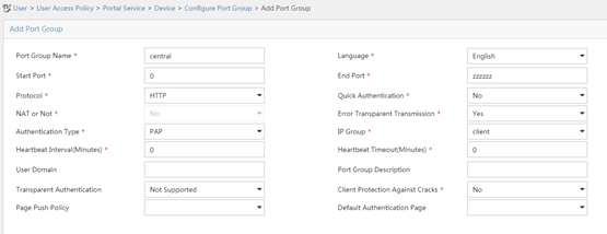
8. Associate the portal device with the IP group:
a. Click the Port Group icon ![]() in the Operation field for device NAS to open the port group
configuration page.
in the Operation field for device NAS to open the port group
configuration page.
b. Click Add.
c. Configure the following parameters:
- Port Group Name—Enter the port group name.
- IP Group—Select the configured IP group. The IP address used by the user to access the network must be within this IP address group.
Use the default settings for other parameters.
d. Click OK.
Verifying the configuration
# Verify that the local AC is in R/M state on the central AC. This state indicates that the local AC has come online on the central AC.
[Central AC] display wlan local-ac all
Total number of local ACs: 1
Total number of connected local ACs: 1
Local AC Information
State : I = Idle, J = Join, JA = JoinAck, IL = ImageLoad
C = Config, DC = DataCheck, R = Run
AC name ACID State Model Serial ID
wx3540h 2 R/M WX3540H 210235A1JQB161000013
# Verify that the AP is in R/M state on the central AC. This state indicates that the local AC has established a management tunnel with the central AC after AC rediscovery.
[Central AC] display wlan ap all
Total number of APs: 1
Total number of connected APs: 1
Total number of connected manual APs: 1
Total number of connected auto APs: 0
Total number of connected common APs: 1
Total number of connected WTUs: 0
Total number of inside APs: 0
Maximum supported APs: 1536
Remaining APs: 1535
Total AP licenses: 1024
Local AP licenses: 1024
Server AP licenses: 0
Remaining Local AP licenses: 1023
Sync AP licenses: 0
AP information
State : I = Idle, J = Join, JA = JoinAck, IL = ImageLoad
C = Config, DC = DataCheck, R = Run, M = Master, B = Backup
AP name APID State Model Serial ID
ap1 4 R/M WA6320 219801A28N819CE0002T
# Verify that the AP has associated with the local AC.
[Central AC] display wlan ap-distribution all
Central AC Slot 2 Total Number of APs: 0
Local AC wx3540h Total Number of APs: 1
AP name AP ID AP IP AC IP
ap1 4 12:1:1::4 12:1:1::1
# Verify that a client has come online.
[Central AC] display wlan client ipv6
MAC address AP name IPv6 address VLAN
e49a-dc71-a162 ap1 2003::3 20
# Verify that the client has passed portal authentication.
[Central AC] display portal user all
Total portal users: 1
Username: qucf
AP name: ap1
Radio ID: 1
SSID: qucf-portal
Portal server: imc
State: Online
VPN instance: N/A
MAC IP VLAN Interface
e49a-dc71-a162 2003::3 20 WLAN-BSS2/0/2
Authorization information:
DHCP IP pool: N/A
User profile: N/A
Session group profile: N/A
ACL number: N/A
Inbound CAR: N/A
Outbound CAR: N/A
Configuration files
· Central AC:
#
vlan 11
#
wlan service-template portal
ssid portal
vlan 20
client forwarding-location ap
akm mode psk
preshared-key pass-phrase cipher $c$3$p0PjuXJ5pGfJ6Z1XDkGRsPR8JoPhrP60GyRn
cipher-suite ccmp
security-ie rsn
client ipv6-snooping nd-learning enable
client ipv6-snooping dhcpv6-learning enable
portal enable method direct
portal domain imc
portal bas-ip 1::1:0:0:2
portal apply web-server imc
service-template enable
#
interface Vlan-interface11
ipv6 address 1::1:0:0:2/96
#
interface GigabitEthernet1/0/1
port link-type trunk
port trunk permit vlan 11
#
radius scheme imc
primary authentication ipv6 1::3:0:0:2
primary accounting ipv6 1::3:0:0:2
key authentication cipher $c$3$hpDUnHfwXg6gyIvCDstC9zAc8UJueLbLTt/i
key accounting cipher $c$3$UzY7a5vF6zEHEdxpnfv+NBQ2UAhUEbjM+8sZ
user-name-format without-domain
nas-ip ipv6 1::1:0:0:2
#
domain imc
authentication portal radius-scheme imc
authorization portal radius-scheme imc
accounting portal radius-scheme imc
#
portal web-server imc
url http://[1::3:0:0:2]:8080/portal
url-parameter apmac ap-mac
url-parameter ssid ssid
url-parameter userip source-address
url-parameter usermac source-mac
#
portal server imc
ipv6 1::3:0:0:2 key cipher $c$3$G0fWl7UQ9AqnAdOJEnlECL+tSwqQbmV2SuRe
#
wlan ap ap1 model WA6320
serial-id 219801A28N819CE0002T
#
wlan ap-group group1
ap ap1
ap-model WA6320
map-configuration cfa0:/map.txt
control-address enable
control-address ipv6 1::1:0:0:104
radio 1
radio enable
service-template portal
radio 2
radio enable
service-template portal
#
wlan local-ac name wx3540h model WX3540H
serial-id 210235A1JQB161000013
· Local AC:
#
dhcp enable
#
vlan 11 to 12
#
vlan 20
#
ipv6 dhcp pool ap
network 12:1:1::/64
option 52 hex 00010000000000000001000000000001
#
ipv6 dhcp pool client
network 2003::/64
#
interface Vlan-interface11
ipv6 address 1::1:0:0:104/96
#
interface Vlan-interface12
ipv6 dhcp select server
ipv6 dhcp server apply pool ap
ipv6 address 12:1:1::1/64
ipv6 nd autoconfig managed-address-flag
ipv6 nd autoconfig other-flag
undo ipv6 nd ra halt
#
interface Vlan-interface20
ipv6 dhcp select server
ipv6 dhcp server apply pool client
ipv6 address 2003::1/64
ipv6 nd autoconfig managed-address-flag
ipv6 nd autoconfig other-flag
undo ipv6 nd ra halt
#
interface GigabitEthernet1/0/1
port link-type trunk
port trunk permit vlan 12 20
port trunk pvid vlan 12
#
interface GigabitEthernet1/0/2
port link-type trunk
port trunk permit vlan 12 20
port trunk pvid vlan 12
#
interface GigabitEthernet1/0/3
port link-type access
port access vlan 11
#
wlan local-ac enable
wlan local-ac capwap source-vlan 11
#
wlan central-ac ipv6 1::1:0:0:2
#
#
ipv6 route-static 0:0::0:0 0 1::1:0:0:2
Related documentation
· AC Hierarchy Command Reference in H3C Access Controllers Command References
· AC Hierarchy Configuration Guide in H3C Access Controllers Configuration Guides
· User Access and Authentication Command Reference in H3C Access Controllers Command References
· User Access and Authentication Configuration Guide in H3C Access Controllers Configuration Guides
· WLAN Advanced Features Command Reference in H3C Access Controllers Command References
· WLAN Advanced Features Configuration Guide in H3C Access Controllers Configuration Guides